WO2017110119A1 - Procédé d'expédition et système d'expédition pour produits - Google Patents
Procédé d'expédition et système d'expédition pour produits Download PDFInfo
- Publication number
- WO2017110119A1 WO2017110119A1 PCT/JP2016/070826 JP2016070826W WO2017110119A1 WO 2017110119 A1 WO2017110119 A1 WO 2017110119A1 JP 2016070826 W JP2016070826 W JP 2016070826W WO 2017110119 A1 WO2017110119 A1 WO 2017110119A1
- Authority
- WO
- WIPO (PCT)
- Prior art keywords
- product
- information
- case
- tag
- order
- Prior art date
Links
Images


Classifications
-
- B—PERFORMING OPERATIONS; TRANSPORTING
- B65—CONVEYING; PACKING; STORING; HANDLING THIN OR FILAMENTARY MATERIAL
- B65G—TRANSPORT OR STORAGE DEVICES, e.g. CONVEYORS FOR LOADING OR TIPPING, SHOP CONVEYOR SYSTEMS OR PNEUMATIC TUBE CONVEYORS
- B65G1/00—Storing articles, individually or in orderly arrangement, in warehouses or magazines
- B65G1/02—Storage devices
- B65G1/04—Storage devices mechanical
- B65G1/137—Storage devices mechanical with arrangements or automatic control means for selecting which articles are to be removed
- B65G1/1371—Storage devices mechanical with arrangements or automatic control means for selecting which articles are to be removed with data records
-
- B—PERFORMING OPERATIONS; TRANSPORTING
- B65—CONVEYING; PACKING; STORING; HANDLING THIN OR FILAMENTARY MATERIAL
- B65B—MACHINES, APPARATUS OR DEVICES FOR, OR METHODS OF, PACKAGING ARTICLES OR MATERIALS; UNPACKING
- B65B5/00—Packaging individual articles in containers or receptacles, e.g. bags, sacks, boxes, cartons, cans, jars
- B65B5/04—Packaging single articles
-
- B—PERFORMING OPERATIONS; TRANSPORTING
- B65—CONVEYING; PACKING; STORING; HANDLING THIN OR FILAMENTARY MATERIAL
- B65B—MACHINES, APPARATUS OR DEVICES FOR, OR METHODS OF, PACKAGING ARTICLES OR MATERIALS; UNPACKING
- B65B51/00—Devices for, or methods of, sealing or securing package folds or closures; Devices for gathering or twisting wrappers, or necks of bags
- B65B51/10—Applying or generating heat or pressure or combinations thereof
-
- B—PERFORMING OPERATIONS; TRANSPORTING
- B65—CONVEYING; PACKING; STORING; HANDLING THIN OR FILAMENTARY MATERIAL
- B65B—MACHINES, APPARATUS OR DEVICES FOR, OR METHODS OF, PACKAGING ARTICLES OR MATERIALS; UNPACKING
- B65B57/00—Automatic control, checking, warning, or safety devices
- B65B57/10—Automatic control, checking, warning, or safety devices responsive to absence, presence, abnormal feed, or misplacement of articles or materials to be packaged
-
- B—PERFORMING OPERATIONS; TRANSPORTING
- B65—CONVEYING; PACKING; STORING; HANDLING THIN OR FILAMENTARY MATERIAL
- B65B—MACHINES, APPARATUS OR DEVICES FOR, OR METHODS OF, PACKAGING ARTICLES OR MATERIALS; UNPACKING
- B65B61/00—Auxiliary devices, not otherwise provided for, for operating on sheets, blanks, webs, binding material, containers or packages
- B65B61/20—Auxiliary devices, not otherwise provided for, for operating on sheets, blanks, webs, binding material, containers or packages for adding cards, coupons or other inserts to package contents
-
- B—PERFORMING OPERATIONS; TRANSPORTING
- B65—CONVEYING; PACKING; STORING; HANDLING THIN OR FILAMENTARY MATERIAL
- B65B—MACHINES, APPARATUS OR DEVICES FOR, OR METHODS OF, PACKAGING ARTICLES OR MATERIALS; UNPACKING
- B65B7/00—Closing containers or receptacles after filling
- B65B7/16—Closing semi-rigid or rigid containers or receptacles not deformed by, or not taking-up shape of, contents, e.g. boxes or cartons
-
- B—PERFORMING OPERATIONS; TRANSPORTING
- B65—CONVEYING; PACKING; STORING; HANDLING THIN OR FILAMENTARY MATERIAL
- B65C—LABELLING OR TAGGING MACHINES, APPARATUS, OR PROCESSES
- B65C1/00—Labelling flat essentially-rigid surfaces
- B65C1/02—Affixing labels to one flat surface of articles, e.g. of packages, of flat bands
-
- B—PERFORMING OPERATIONS; TRANSPORTING
- B65—CONVEYING; PACKING; STORING; HANDLING THIN OR FILAMENTARY MATERIAL
- B65D—CONTAINERS FOR STORAGE OR TRANSPORT OF ARTICLES OR MATERIALS, e.g. BAGS, BARRELS, BOTTLES, BOXES, CANS, CARTONS, CRATES, DRUMS, JARS, TANKS, HOPPERS, FORWARDING CONTAINERS; ACCESSORIES, CLOSURES, OR FITTINGS THEREFOR; PACKAGING ELEMENTS; PACKAGES
- B65D75/00—Packages comprising articles or materials partially or wholly enclosed in strips, sheets, blanks, tubes, or webs of flexible sheet material, e.g. in folded wrappers
- B65D75/52—Details
- B65D75/54—Cards, coupons, or other inserts or accessories
-
- B—PERFORMING OPERATIONS; TRANSPORTING
- B65—CONVEYING; PACKING; STORING; HANDLING THIN OR FILAMENTARY MATERIAL
- B65D—CONTAINERS FOR STORAGE OR TRANSPORT OF ARTICLES OR MATERIALS, e.g. BAGS, BARRELS, BOTTLES, BOXES, CANS, CARTONS, CRATES, DRUMS, JARS, TANKS, HOPPERS, FORWARDING CONTAINERS; ACCESSORIES, CLOSURES, OR FITTINGS THEREFOR; PACKAGING ELEMENTS; PACKAGES
- B65D77/00—Packages formed by enclosing articles or materials in preformed containers, e.g. boxes, cartons, sacks or bags
- B65D77/10—Container closures formed after filling
- B65D77/20—Container closures formed after filling by applying separate lids or covers, i.e. flexible membrane or foil-like covers
- B65D77/2024—Container closures formed after filling by applying separate lids or covers, i.e. flexible membrane or foil-like covers the cover being welded or adhered to the container
-
- B—PERFORMING OPERATIONS; TRANSPORTING
- B65—CONVEYING; PACKING; STORING; HANDLING THIN OR FILAMENTARY MATERIAL
- B65D—CONTAINERS FOR STORAGE OR TRANSPORT OF ARTICLES OR MATERIALS, e.g. BAGS, BARRELS, BOTTLES, BOXES, CANS, CARTONS, CRATES, DRUMS, JARS, TANKS, HOPPERS, FORWARDING CONTAINERS; ACCESSORIES, CLOSURES, OR FITTINGS THEREFOR; PACKAGING ELEMENTS; PACKAGES
- B65D81/00—Containers, packaging elements, or packages, for contents presenting particular transport or storage problems, or adapted to be used for non-packaging purposes after removal of contents
- B65D81/02—Containers, packaging elements, or packages, for contents presenting particular transport or storage problems, or adapted to be used for non-packaging purposes after removal of contents specially adapted to protect contents from mechanical damage
- B65D81/05—Containers, packaging elements, or packages, for contents presenting particular transport or storage problems, or adapted to be used for non-packaging purposes after removal of contents specially adapted to protect contents from mechanical damage maintaining contents at spaced relation from package walls, or from other contents
-
- B—PERFORMING OPERATIONS; TRANSPORTING
- B65—CONVEYING; PACKING; STORING; HANDLING THIN OR FILAMENTARY MATERIAL
- B65G—TRANSPORT OR STORAGE DEVICES, e.g. CONVEYORS FOR LOADING OR TIPPING, SHOP CONVEYOR SYSTEMS OR PNEUMATIC TUBE CONVEYORS
- B65G1/00—Storing articles, individually or in orderly arrangement, in warehouses or magazines
- B65G1/02—Storage devices
- B65G1/04—Storage devices mechanical
- B65G1/137—Storage devices mechanical with arrangements or automatic control means for selecting which articles are to be removed
Definitions
- the present invention relates to a product shipping method and a shipping system.
- the picking process is a process of picking target products in a warehouse and collecting them in trays or containers.
- the boxing process is a process of putting picked products from a tray or the like into a shipping case.
- the packaging process is a process of packaging the product by closing and sealing the opening of the case. In the packaging process, it is conceivable to use a sealing device for attaching a lid (cover film) to the case.
- the present invention has been made in view of the above circumstances, and an object of the present invention is to provide a product shipping method and a shipping system that can more reliably prevent erroneous product shipment.
- Means 1 At least product information that is information that can identify the attached product is stored, and the product information IC tag that is configured to be able to read the stored product information from the outside, among a plurality of products that are each attached, A picking process for picking a product based on order product information, which is information that can identify the ordered product, Based on the ordered product information, a verification process for verifying the picked product, A boxing process for picked products for case for shipping products, A packaging step of attaching a predetermined cover film to the case so that the product placed in the case cannot be removed, and packaging the product with a packaging body including the case and the cover film; A label issuing process for issuing a mailing label with a destination of the packaged product; A label attaching step for attaching the address label to the package; A method of shipping goods including Prior to the picking step, order information including at least destination information that can identify a destination of the product and order information including the order product information is stored, and the received order information is configured so that the stored order information can be read from the outside.
- the picking step and the boxing step can be executed as a series of operations of picking a product and putting the picked product into the dedicated case based on the product specification with the IC tag of the dedicated case.
- the verification step after the boxing step, the product information IC tag of the product put in the dedicated case, and the order information IC tag of the product specification with the IC tag in the dedicated case from outside the product The information and the order product information are read, and by checking based on both the read information, it is determined whether or not an appropriate product is contained in the dedicated case.
- the cover film is attached to the case of the dedicated case that is determined to contain an appropriate product in the collating step, whereby the product and the IC tag-attached product are provided by the packaging body.
- the statement is packed,
- the label issuing step the destination information is read from the order information IC tag of the product specification with the IC tag in the dedicated case, and the address label is issued based on the read destination information.
- the shipping method for the product is
- the “product information” and “order received product information” include not only information that can directly specify the product, such as product name, JAN code, and model number, but also information that can indirectly specify the product (for example, product The management number assigned to each product in the database is also included.
- destination information not only information that can directly specify a destination such as the address and address of the product destination, but also information that can indirectly specify the destination (eg, the address and address of the product destination) Order number etc.) (hereinafter the same).
- a dedicated case can be obtained by setting the case and the product description with the IC tag as a set in the dedicated case acquisition process prior to the picking process.
- the dedicated case can be said to be a case corresponding to only the ordered product, and is used for shipping the product as it is.
- an operator can perform picking process and boxing process as a series of operations by picking a product based on the IC tag product specification of the special case and putting the picked product into the special case. It becomes possible. Therefore, in the picking process, it is possible to save the trouble of transferring the product from the tray to the shipping case as compared with the case where the product is once placed (collected) on the picking tray or the like.
- the product information and the order product information are read from the outside from the product information IC tag and the order information IC tag contained in the special case, and collation based on both information is performed. It is determined whether or not an appropriate product is contained in the dedicated case. That is, since it is determined whether or not the product is appropriate without touching the product, it is not necessary to put out the product from the dedicated case in the collation process.
- the product does not normally enter and exit from the case after the picking process. Therefore, it is possible to remarkably reduce the occurrence of forgetting to put in a product or mistakes in putting. As a result, it is possible to more surely prevent shipping of wrong products (different from the order contents).
- the destination information is read from the order information IC tag of the product specification with the IC tag in the dedicated case, and the address label is issued based on the read destination information. That is, an address label is issued for each dedicated case. Therefore, it is possible to more reliably prevent the product from being shipped to the wrong destination.
- the product is packaged by attaching the cover film to the case of the dedicated case that is determined to contain an appropriate product in the verification process.
- the cover film is not attached to the case containing the wrong product, and the product or the like is not packaged. Accordingly, useless packaging is not performed, and the cost can be reduced.
- the wrong product is not packaged and cannot be shipped. For this reason, it is possible to more reliably prevent an erroneous product from being shipped.
- the product information and the order product information are read from the outside from the product information IC tag and the order information IC tag in the package, and collation based on both the read information is performed.
- Means 3 The method for shipping goods according to means 1 or 2, wherein a plurality of types of different sizes are used as the case.
- the product can be accommodated in a case of an appropriate size suitable for the size and the like, and an increase in cost related to transportation and the like can be suppressed.
- the cover film is attached to the case by a predetermined sealing means,
- the cover film can be properly attached to the various cases, and the packaging quality can be improved.
- the product specification with IC tag includes case designation information for designating the case to be set with itself, and the case designated by the case specification information is an order received according to the product specification with IC tag.
- the “case designation information” may be written in characters or the like in the product specification with IC tag, or may be input as electronic information in the order information IC tag of the product specification with IC tag. Further, the “case designation information” may be automatically calculated based on the size and number of ordered products by a predetermined calculation means (the same applies hereinafter). According to the means 5, the case specification information is included in the IC tag product specification, and the case specified by the case specification information has a size capable of storing the ordered product. Therefore, when the picking is completed, all the ordered products are accommodated in the special case.
- Means 6. The method of shipping a product according to any one of means 1 to 5, further comprising a progress notification step for notifying a product orderer of the progress of each of the steps related to shipping of the ordered product.
- the orderer in the progress notification step, for example, an e-mail is transmitted to the orderer side of the product.
- the orderer can grasp the progress status related to the shipping operation of the ordered product, and can eliminate the anxiety and dissatisfaction of the orderer when the progress status is unknown.
- the case is A pocket for accommodating the product, A flange portion formed to extend outward from the opening end of the pocket portion,
- the cover film is attached to the flange portion of the case by a predetermined sealing means,
- the sealing means includes The cover film having an upper layer film in which a through-hole is previously formed at a predetermined position and a predetermined lower layer film is attached so as to close the opening of the pocket portion in a state where a product is accommodated in the pocket portion.
- Pressure contact means for pressing the cover film against the flange portion in a first annular region on the outer peripheral side of the opening peripheral edge of the pocket portion in a state where the product is accommodated in the pocket portion;
- a predetermined gas is supplied between the upper layer film and the lower layer film through the through-holes disposed corresponding to the flange portion, and the pocket portion of the lower layer film is supplied to the pocket portion.
- a gas supply means for bulging a corresponding portion toward the internal space of the pocket portion;
- Attachment means for attaching the cover film to the flange portion so that a space between the film and the lower layer film is in an airtight state in communication with the through hole;
- sealing means may include at least one of the technical matters of the shipping system of means 17 to 24 described later.
- the said means 7 when supplying gas between an upper layer film and a lower layer film through a through-hole, it will be in the state by which the cover film was press-contacted with the flange part in the 1st annular area by the press-contact means. Yes. Therefore, the bulging of the upper layer film can be suppressed in the second annular region located between the opening periphery of the pocket portion and the first annular region. And a cover film is attached with respect to a flange part in a 2nd cyclic
- the product is sandwiched between the case (pocket portion) and the bulging lower layer film. Therefore, the movement of the product in the pocket portion can be restricted, and the product can be more reliably prevented from colliding with the case when vibration is applied to the package. Furthermore, a gap can be formed between the cover film (upper layer film) or case and the product as the lower layer film bulges. Therefore, when an impact is applied to the package, the impact applied to the product can be reduced. Due to these functions and effects, it is possible to more effectively suppress damage to goods during transportation.
- the product between the case and the lower layer film can be adjusted by adjusting the amount of gas to be supplied and adjusting the amount of swelling of the lower layer film according to the size and number of the products. Can be sandwiched with appropriate pressure. Therefore, it can respond flexibly to various products.
- Means 8 A shipping system used for shipping products, A product information IC tag that is attached to each product, stores product information that is information that can identify at least the attached product, and is configured to be able to read the stored product information from the outside, A case for containing the product; Order information including at least destination information that can identify the destination of the product and order product information that can identify the ordered product is stored, and the stored order information can be read from the outside.
- the product information and the order product information are read from the outside from the product information IC tag of the product put in the special case and the order information IC tag of the product specification with the IC tag in the special case.
- a sealing unit that attaches a predetermined cover film to the case of the dedicated case that is determined by the checking unit to contain an appropriate product, and wraps the product with a package including the case and the cover film.
- a label issuing unit that reads the destination information from the order information IC tag of the product specification with the IC tag in the dedicated case, and issues a mailing label on which the destination of the product is written based on the read destination information;
- a shipping system comprising:
- Means 9 By reading the product information and the ordered product information from the outside from the product information IC tag and the order information IC tag in the package, and performing verification based on both the read information, an appropriate product can be found in the package.
- Means 10 The shipping system according to claim 8 or 9, wherein there are a plurality of types of cases having different sizes.
- Means 11 The shipping system according to claim 10, wherein there are a plurality of different sealing means corresponding to the type of the case.
- the product specification with IC tag includes case designation information for designating the case to be set with itself, and the case designated by the case specification information is an order received according to the product specification with IC tag.
- the shipping system according to means 10 or 11, characterized in that a commodity can be stored.
- the picking cart includes a specification tag reading means capable of reading at least the order product information from the order information IC tag of the IC tag product specification,
- the shipping system according to any one of means 8 to 12, further comprising a cart display means capable of displaying information based on the order product information read by the specification tag reading means.
- the “information based on the order product information” may be the order product information itself, or various information stored in association with the order product information (for example, the place and size of the product, and the precautions regarding the product) Etc.).
- the information is displayed on the cart display means based on the order product information read by the specification tag reading means. Accordingly, picking work can be easily performed based on displayed information, and convenience and workability can be improved. In addition, it is possible to suppress the occurrence of picking mistakes (product selection mistakes during picking).
- Means 14. The shipment system according to any one of means 8 to 13, further comprising a progress notification means capable of executing a progress notification operation for notifying a product orderer of a progress state of a process related to shipment of the ordered product. .
- the “progress notification operation” for example, an operation for transmitting an e-mail for notifying the progress status of each process to the orderer (specified e-mail address), or according to a request from the orderer,
- movement which transmits the information for notifying the progress state of each process to the orderer side etc. can be mentioned.
- the order product information stored in the order information IC tag is not information that can directly specify a product, but information that is associated with the product and that can indirectly specify the product. 14.
- the shipping system according to any one of 14.
- the order information IC tag stores, as the ordered product information, for example, information that can indirectly identify the product, such as a management number associated with the product, and the product name such as the product name. Information that can directly specify is not stored. Therefore, even after a third party reads the information of the order information IC tag from outside after the shipment, it is almost impossible to specify the product based on the read information. Thereby, an orderer's privacy can be protected more reliably.
- the case is A pocket for accommodating the product, A flange portion formed to extend outward from the opening end of the pocket portion,
- the sealing means includes The cover film having an upper layer film in which a through-hole is previously formed at a predetermined position and a predetermined lower layer film is attached so as to close the opening of the pocket portion in a state where a product is accommodated in the pocket portion.
- Pressure contact means for pressing the cover film against the flange portion in a first annular region on the outer peripheral side of the opening peripheral edge of the pocket portion in a state where the product is accommodated in the pocket portion;
- a predetermined gas is supplied between the upper layer film and the lower layer film through the through-holes disposed corresponding to the flange portion, and the pocket portion of the lower layer film is supplied to the pocket portion.
- a gas supply means for bulging a corresponding portion toward the internal space of the pocket portion;
- Attachment means for attaching the cover film to the flange portion so that a space between the film and the lower layer film is in an airtight state in communication with the through hole;
- the pressure contact means is A chamber part having an internal space to which gas is supplied from the gas supply means, the internal space opening toward the opening side of the pocket part in the case; A support part arranged at a position sandwiching the cover film and the case between the opening side end part of the internal space in the chamber part, The cover film and the flange portion are sandwiched between the opening-side end portion and the support portion of the chamber portion so that the through hole and the internal space of the chamber portion communicate with each other with respect to the flange portion. Press the film, The gas supply means is configured to supply gas between the upper layer film and the lower layer film through the through hole by supplying gas to the internal space of the chamber portion.
- the shipping system according to means 16.
- the gas is supplied from the gas supply means between the upper layer film and the lower layer film through the internal space of the chamber part constituting the pressure contact means. That is, the press contact means has a function as a gas flow path as well as a function of pressing the cover film against the flange portion. Therefore, it is not necessary to separately provide an instrument for supplying gas between the films from the gas supply means (for example, a pipe inserted between the films through the through hole). As a result, the apparatus can be simplified and the cost can be reduced.
- the attachment means includes A seal portion having a heat generating portion having a shape corresponding to the second annular region; A receiving portion arranged at a position sandwiching the cover film and the case between the heat generating portion, By sandwiching the flange part and the cover film by the heat generating part and the receiving part, the cover film is configured to be heat-sealed to the flange part,
- the shipping system according to claim 16 or 17, wherein the heat generating part is disposed in an internal space of the chamber part.
- the heat generating part of the attaching means is arranged in the internal space of the chamber part. Therefore, the unit of the apparatus can be improved, and the apparatus can be more reliably downsized.
- Means 19 Punching an intermediate package formed by attaching the cover film to the flange portion by the attaching means, and a punching means for obtaining the package is provided; Any of the means 16 to 18 characterized in that the punching means is configured to punch the intermediate package at a position where the through hole does not exist in the package obtained by punching.
- Means 20 The shipment according to any one of means 16 to 19, wherein the case is formed with a hole for allowing air in the pocket portion to escape when the lower film is bulged. system.
- the pocket portion includes a rib portion formed to protrude toward the inner space side,
- the gas supply means is configured to bulge the lower layer film by gas supply so that the product is pressed against the rib portion.
- a gap can be formed between the pocket portion and the product by the rib portion.
- Means 22 The shipping system according to claim 21, wherein the rib portion has a frustum shape that gradually narrows toward a tip end side of the rib portion to which the product is pressed.
- the tip of the rib part when the product is pressed against the tip of the rib part as the lower layer film bulges, the tip of the rib part is easily crushed and deformed. Thereby, it can suppress that the pressure added with respect to goods from a rib part increases too much. Further, the product can be more securely sandwiched and held by the bulging lower layer film and the crushed rib portion. As a result, in the obtained package, it is possible to more effectively prevent the product from being damaged.
- Means 23 When the gas is supplied between the upper layer film and the lower layer film by the gas supply means, the upper layer is in contact with or close to the upper layer film on the opening of the pocket portion, and is directed to the opposite side to the inside of the pocket portion. 23.
- the shipping system according to any one of means 16 to 22, further comprising a bulge restricting means for restricting the bulge of the film.
- the swelling of the upper film can be more reliably suppressed by the swelling restriction means. Therefore, it is possible to prevent deterioration of the appearance quality due to excessive swelling of the upper layer film, and more reliably seal both films while enclosing sufficient gas between the upper layer film and the lower layer film in order to suppress damage to the product. be able to. Therefore, it is possible to more reliably obtain a package that can suppress damage to the product.
- Means 24 The shipping system according to any one of means 16 to 23, wherein the upper film is thicker than the lower film.
- the above means 24 it is possible to further suppress the swelling of the upper layer film when the gas is filled between the upper layer film and the lower layer film. Therefore, the upper layer film and the lower layer film can be more easily and more reliably sealed. As a result, it is possible to more reliably obtain a package that can suppress damage to the product.
- FIG. 1 it is a partial expanded cross-section schematic diagram which shows a mode that the air in a pocket part escapes. It is sectional drawing which shows the control part in another embodiment. It is sectional drawing which shows the control part in another embodiment. It is sectional drawing which shows the control part in another embodiment. It is sectional drawing which shows the control part in another embodiment.
- the shipping system 10 includes a server 11, a product information IC tag 12, a case 13, a specification issuing device 14 as a specification issuing device, a picking cart 15, a verification device 16 as a verification device, a seal
- the unit 17 includes a label issuing / attaching device 18 as a label issuing means, a tag reading device 19 at the time of shipment, and the like.
- the product W is picked and packaged, and the packaged product W is finally shipped.
- the product W include a DVD, a CD, and various miscellaneous goods housed in a package.
- the goods W are accommodated, for example, in a storage shelf SH (see FIG.
- the product information IC tag 12 is attached to each product W one by one.
- the case 13, the specification issuing device 14, the picking cart 15, the collating device 16, the seal unit 17, the label issuing / attaching device 18 and the shipping tag reading device 19 are placed in the warehouse.
- the server 11 is placed at a location different from the warehouse. In FIG. 1, the flow of information is indicated by a thick arrow, and the flow of an object is indicated by a dotted arrow.
- the server 11 is configured as a so-called computer system including a CPU as a calculation means, a ROM that stores various programs, and a RAM that temporarily stores various data such as calculation data and input / output data.
- the server 11 is configured to be able to transmit and receive information to and from each device, and controls the operation of each device and outputs necessary information to each device in response to a request from each device.
- the server 11 is communicable with a product management storage device 21 in which various information for managing products is stored, and an order management storage device 22 in which various information related to product orders is stored. Information stored in these storage devices 21 and 22 is managed.
- the merchandise management storage device 21 includes, for example, merchandise information such as merchandise name, release date, price, model number, JAN code, merchandise storage location, merchandise size, merchandise precautions, and management information associated therewith. Numbers are stored in a database. Of these pieces of information, the product name, management number, model number, and JAN code correspond to product information that can identify the product.
- the order management storage device 22 includes information such as the product name of the ordered product and the management number associated therewith, the number of products, the address of the orderer, the destination of the product, the e-mail address designated by the orderer, and the like.
- the order numbers associated with these are stored in a database. These pieces of information correspond to order information.
- the product name of the ordered product and the management number associated therewith correspond to the ordered product information that can identify the ordered product.
- the address of the orderer, the destination of the product, and the order number among these pieces of information correspond to destination information that can specify the destination of the product (the above is only an example).
- the server 11 when new information is stored in the order management storage device 22, that is, when a new order is entered, the server 11 outputs the order product information and the destination information to the statement issuing device 14.
- the product name and the management number associated therewith are output as the order product information, and the order number is output as the destination information.
- the server 11 also outputs to the statement issuing device 14 information related to the placement of the product related to the ordered product.
- the server 11 obtains the size and number of the ordered product by referring to the size of the product stored in the product management storage device 21 and the number of products stored in the order management storage device 22. In addition, it has a function of deriving case designation information based on the obtained information.
- the server 11 outputs the case designation information to the statement issuing device 14 together with the order product information and the destination information.
- the case designation information designates the type of the case 13 to be selected from among the cases 13 that exist in a plurality of types.
- the case 13 designated by the case designation information can store all of the ordered products.
- the server 11 stores in advance a predetermined algorithm for deriving an appropriate type of case 13 based on the size and number of products, and the case designation information is derived using this algorithm.
- the server 11 transmits an e-mail corresponding to the input completion signal to a predetermined mail address stored in the order management storage device 22.
- This e-mail transmission operation corresponds to a progress notification operation. That is, the server 11 has a function as progress notification means. The operation of the server 11 related to the transmission of the e-mail will be described together with the description of the configuration of each device that outputs a completion signal.
- the merchandise information IC tag 12 has an integrated circuit for storing information and an antenna connected to the integrated circuit.
- the antenna is used for reading information stored in the integrated circuit and writing information to the integrated circuit, and transmits and receives predetermined radio waves.
- An antenna can read and write information to and from the integrated circuit from the outside without contact. This configuration is the same in the order information IC tag 32 described later.
- one product information IC tag 12 is attached to each of the products W, and the product information IC tag 12 is product information that is information that can identify the attached product W. Is stored in advance.
- the management number is stored as product information, and the stored product information can be read from the outside via the antenna.
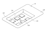
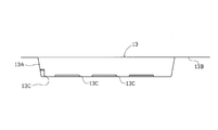
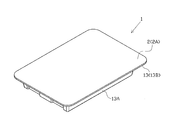
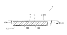
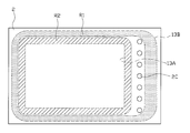
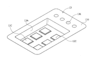
- the case 13 is made of a thermoplastic resin material such as PP (polypropylene), PVC (polyvinyl chloride), or PE (polyethylene). 2 and 3, the case 13 includes a pocket portion 13A for storing the product W and an annular flange portion 13B formed to extend outward from the opening end of the pocket portion 13A. I have.
- PP polypropylene
- PVC polyvinyl chloride
- PE polyethylene
- a plurality of rib portions 13C are formed on the bottom wall portion and the side wall portion of the pocket portion 13A so as to project toward the internal space side of the pocket portion 13A.
- Each rib part 13C has a role which supports the goods W by contacting the goods W.
- what was provided in the bottom wall part of the pocket part 13A among the rib parts 13C has made the shape which becomes gradually thin toward the front-end
- a quadrangular frustum shape is formed.
- the rib portion 13C may have a frustum shape other than the quadrangular frustum shape (for example, a frustum shape, a triangular frustum shape, a polygonal frustum shape, etc.).
- a hole 13D is formed through the center of the bottom wall of the pocket 13A.
- the hole portion 13D is provided at a position deviated from the formation position of the rib portion 13C, and the hole portion 13D is not blocked by the product W when the product W is accommodated in the pocket portion 13A.
- case 13 there are a plurality of different types such as the opening area and depth of the pocket portion 13A.
- cases 13 there are three types of cases 13 in which the volumes of the pocket portions 13A are different. Of course, more various cases 13 may be used.
- the case 13 shown in FIGS. 2 and 3 has the smallest volume of the pocket portion 13A.
- the statement issuing device 14 issues a product specification 31 with an IC tag including an order information IC tag 32.
- the specification issuing device 14 includes an information writing device for storing information in an IC tag that can write and read information from outside, and receives order product information (product name) from the server 11. , Management number), destination information (order number), information regarding product placement, and case designation information are input to the IC tag by the information writing device.
- the order information IC tag 32 storing the order product information (management number) and the destination information (order number) is obtained.
- the statement issuing device 14 includes a printing device capable of printing on a predetermined sheet.
- the order product information product name, management number
- the product description is obtained by printing the product name, product storage location, and case designation information on a sheet by the printing means.
- an order information IC tag 32 to the obtained product specification, a product specification 31 with IC tag is issued.
- An IC tag may be attached to the paper in advance, information may be printed on the paper, and information may be input to the attached IC tag.
- the product specification 31 with IC tag is a set with the case 13, and the order product according to the product specification 31 with IC tag is obtained by setting the case 13 and the product specification 31 with IC tag.
- a special case 33 corresponding only to the above is obtained.
- the dedicated case 33 is used not only for picking products but also for shipping products.
- the picking cart 15 is a cart used at the time of picking a product, and is usually used in a state where the dedicated case 33 is placed. More specifically, the picking cart 15 is used such that when it is pushed by the worker, the picking cart 15 is moved together with the worker to the target product place, and the picked product is put in the placed special case 33. To do.
- the picking cart 15 controls the operation of the specification tag reading device 15A as the specification tag reading means, the cart display device 15B as the cart display means, and these devices 15A and 15B, and is wireless with the server 11. And a cart control device (not shown) configured to be communicable.
- the specification tag reader 15 ⁇ / b> A is capable of reading the order product information (management number) from the order information IC tag 32 of the product specification 31 with IC tag from the outside.
- the cart display device 15B is composed of, for example, a liquid crystal panel and displays information based on the order product information read by the specification tag reader 15A.
- the cart control device inquires of the server 11 about the management number read.
- the server 11 inquired of the management number extracts the product name of the product associated with the management number, information on the storage location, and the precautions from the product management storage device 21, and uses these information as the cart control device.
- the cart control device causes the cart display device 15B to display information on the product name, the product storage location, and the precautions.
- the picking work is performed on the basis of information related to the place for the product shown in the cart display device 15B and the product specification 31 with the IC tag.
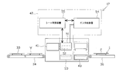
- the dedicated case 33 in which the product W is put using the picking cart 15 is conveyed to the verification device 16 by a predetermined stacking conveyor 34.
- the stacking conveyor 34 includes one main conveyor 34A connected to the verification device 16 and a plurality of branch conveyors 34B connected to the main conveyor 34A (see FIG. 17), and basically dedicated to the branch conveyor 34B.
- the collation device 16 includes an IC tag reader that can read the information of the IC tag from the outside. By using this device, whether or not the product W put in the special case 33 matches the ordered product. That is, it is determined whether or not an appropriate product W is contained. Specifically, from the product information IC tag 12 of the product W put in the special case 33 by the IC tag reader and the order information IC tag 32 of the product specification 31 with the IC tag in the special case 33, The product information and the order product information (in this embodiment, both information are management numbers) are read. Then, collation is performed based on both pieces of read information (specifically, it is determined whether or not both pieces of read information match), thereby determining whether or not an appropriate product W is contained in the dedicated case 33. To do. The collation device 16 acquires destination information (order number) in addition to the order product information from the order information IC tag 32.
- the dedicated case 33 determined by the verification device 16 as not containing an appropriate product is discharged to a predetermined defect discharge conveyor 35 (see FIG. 17) by a predetermined defect discharge device (not shown).
- the verification device 16 when it is determined that an appropriate product is contained, the verification device 16 outputs a verification completion signal, which is a signal indicating that the verification is completed, to the server 11 together with the read destination information (order number).
- the server 11 to which the destination information (order number) and the verification completion signal are input acquires the mail address designated by the orderer corresponding to the destination information from the order management storage device 22 based on the input destination information. To do. Then, an e-mail indicating that the picking is completed is transmitted to this e-mail address.
- the dedicated case 33 determined by the verification device 16 to contain an appropriate product is conveyed to the seal unit 17 by the branch conveyor 36.
- the branch conveyor 36 is used to convey the dedicated case 33 having different sizes of the case 13 to an appropriate seal unit 17 that matches the size of the case 13.
- a device for reading the information of the IC tag from the outside is provided at the most upstream part of the branch conveyor 36, and the case designation information of the order information IC tag 32 is read by the device. Then, based on the read case designation information, the seal unit 17 serving as a transport destination is selected, and the dedicated case 33 is transported to the selected seal unit 17.
- the seal unit 17 attaches the cover film 2 for closing the opening to the case 13 of the dedicated case 33.
- a plurality (three in this embodiment) of different seal units 17 corresponding to the type of the case 13 are provided.
- Each seal unit 17 is different only in that the sizes of the parts constituting the apparatus are different in order to correspond to the type of the case 13, and the basic configuration is common. Below, the common structure in each seal unit 17 is demonstrated.
- the seal unit 17 includes a film supply device 41, a sealing device 42 as a sealing means, and a punching device 43 as a punching means.
- the special case 33 is conveyed to the film supply device 41, the seal device 42, and the punching device 43 in this order, for example, by a predetermined pickup device.
- the film supply device 41 has a function of supplying the cover film 2 having a size sufficient to close the opening to the case 13 of the dedicated case 33 and placing the cover film 2 on the case 13 so as to close the opening.
- the cover film 2 has a two-layer structure including an upper film 2 ⁇ / b> A and a lower film 2 ⁇ / b> B.
- both strip-shaped films 2 ⁇ / b> A and 2 ⁇ / b> B are separately provided. Have been supplied. Then, the film supply device 41 cuts both the films 2A and 2B to a predetermined size by a predetermined cutting means (not shown), and after stacking the cut films 2A and 2B to the case 13 Place.
- the upper layer film 2A and the lower layer film 2B are formed of a thermoplastic resin compatible with the case 13, and in particular, the lower layer film 2B is formed of a stretchable material (for example, a film having a low degree of stretching). Yes.
- the upper layer film 2A is thicker than the lower layer film 2B and has a high rigidity.
- a plurality of through holes 2C are formed in the upper film 2A. 2 C of through-holes are provided in a line in the direction orthogonal to the said width direction in the width direction one end side of 2 A of upper layer films.
- the cover film 2 is placed on the case 13 so that the through hole 2C overlaps the flange portion 13B.
- the sealing device 42 has a function of attaching the cover film 2 to the case 13 while filling the space between the films 2 ⁇ / b> A and 2 ⁇ / b> B (inert gas, in this embodiment, air).
- in this embodiment, air in this embodiment, air
- the product W and the product specification with IC tag 31 are packaged in an intermediate package 4 (see FIG. 6) composed of the case 13 and the cover film 2.
- the detailed configuration of the sealing device 42 will be described later.
- the punching device 43 includes a predetermined punching cutter (not shown) and the like. By punching the outer edge portion (flange portion 13B) of the intermediate package 4, the product specification with the product W and the IC tag is provided. It is used in order to obtain 31 packaged bodies 1 (see FIGS. 7 and 8). The punching device 43 is set to punch the intermediate package 4 at a position where the through hole 2C does not exist in the package 1 obtained by punching.
- the punching device 43 includes an IC tag reading device capable of reading the information of the IC tag from the outside, and can communicate with the server 11.
- the punching device 43 reads the destination information (order number) from the order information IC tag 32 in the product specification 31 with IC tag in the intermediate package 4 at the time of punching.
- the punching device 43 outputs the read destination information (order number) and a packaging completion signal, which is a signal indicating that the packaging is completed, to the server 11.
- the server 11 to which the destination information and the packaging completion signal are input acquires the mail address designated by the orderer corresponding to the destination information from the order management storage device 22. To do.
- an e-mail indicating that the packaging is completed is transmitted to this e-mail address.
- prescribed gas is filled between both film 2A, 2B, and the lower layer film 2B bulges to the internal space side of the pocket part 13A (refer FIG. 8). . Then, the product W is sandwiched and supported by the bulging lower layer film 2B and the pocket portion 13A (in this embodiment, the rib portion 13C). Furthermore, since the entire area between the outer peripheral edges of the two films 2A and 2B is sealed, the space between the two films 2A and 2B is in an airtight state, and the bulging state of the lower film 2B is maintained. .
- the label issuing / attaching device 18 issues an address label on which an address and a destination are described, and affixes the address label to the surface of the obtained package 1 (upper film 2A).
- the label issuing / attaching device 18 includes a label issuing device and a label sticking device.
- the label issuing device includes an IC tag reader capable of reading the information of the IC tag from the outside, and the destination information (order number) is read from the order information IC tag 32 in the package 1 by the IC tag reader. Then, the server 11 is inquired of the read order number. The server 11 inquired of the order number extracts information on the orderer's address and destination associated with the order number from the order management storage device 22 and outputs the information to the label issuing device. Based on the input information, the label issuing device issues an address label in which the orderer's address and destination are recorded. The issued address label is supplied to a labeling device.
- the label sticking device sticks the supplied address label to the package 1.
- the label sticking device includes an IC tag reader capable of reading the information of the IC tag from the outside, and the order information IC in the package 1 is provided by the IC tag reader when or at the time of sticking the address label.
- the destination information (order number) is read from the tag 32.
- the label issuing device outputs to the server 11 the read destination information (order information) and a label pasting completion signal which is a signal indicating that the pasting of the address label has been completed.
- the server 11 to which the destination information and the label pasting completion signal are input acquires the mail address designated by the orderer corresponding to the destination information from the order management storage device 22 based on the input destination information.
- an e-mail indicating that preparation for shipping has been completed is transmitted to this e-mail address.
- the shipping tag reader 19 is configured to be communicable with the server 11 and is capable of reading IC tag information from the outside.
- the shipping tag reader 19 reads the destination information (order number) from the order information IC tag 32 in the package 1 immediately before the package 1 is shipped (when the package 1 is delivered to the carrier). Then, the read destination information is output to the server 11 together with a shipping completion signal that is a signal indicating that the shipping operation has been completed.
- the server 11 to which the destination information (order number) and the shipment completion signal are input acquires the mail address designated by the orderer corresponding to this destination information from the order management storage device 22 based on the input destination information. To do. Then, an e-mail indicating that the shipment has been completed is transmitted to this e-mail address.
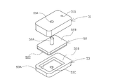
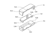
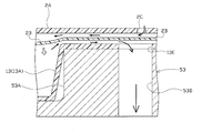
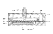
- the seal device 42 includes a chamber portion 51, a seal portion 52, a lower mold 53, a gas supply device 54, and a seal control device 55.
- the chamber part 51 and the lower mold 53 correspond to the pressure contact means
- the seal part 52 and the lower mold 53 correspond to the attachment means.
- the gas supply device 54 is, for example, a compressor, and supplies a predetermined gas (inert gas, air in the present embodiment) to the chamber portion 51. Note that the type of gas supplied from the gas supply device 54 may be changed as appropriate.
- the seal control device 55 is a computer system including a CPU for calculation, a ROM for storing data, a RAM, and the like.
- the operations of the chamber portion 51, the seal portion 52, the lower mold 53, and the gas supply device 54 are controlled by a seal control device 55.
- the seal control device 55 can grasp that the dedicated case 33 or the like has arrived at the seal device 42 by a signal from a sensor (not shown).
- the pocket portion 13A is arranged at a predetermined relative position with respect to the chamber portion 51 or the like.
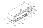
- the chamber 51 is located above the arrived dedicated case 33 and can be moved up and down by a driving means (not shown). Moreover, the chamber part 51 is provided with the internal space 51S opened toward the opening side (surface side of the upper film 2A) of the pocket part 13A in the case 13.
- the opening of the internal space 51S has a shape substantially corresponding to the opening of the pocket portion 13A, and the opening area of the internal space 51S is slightly larger than the opening area of the pocket portion 13A.
- the upper wall portion of the chamber portion 51 is formed with a first series of through holes 51A and a second communication hole 51B that penetrate the upper wall portion and communicate the internal space 51S with the outside.
- the rod-shaped rod portion 52A constituting a part of the seal portion 52 is inserted in the first through hole 51A and can be moved up and down by a driving means (not shown).
- a driving means not shown
- an annular seal member (not shown) that is in close contact with the entire outer periphery of the rod portion 52A is disposed in a portion of the chamber portion 51 where the first through hole 51A is formed.
- the second communication hole 51B is a vent hole for introducing the gas supplied from the gas supply device 54 into the internal space 51S.
- the gas supplied from the gas supply device 54 flows into the internal space 51S through a predetermined gas pipe (not shown) and the second communication hole 51B.
- the gas supply device 54, the gas pipe or the chamber portion 51, and the like are provided with an atmospheric pressure sensor (not shown) for measuring the atmospheric pressure in the internal space 51S. And the signal which shows the information regarding the atmospheric
- the seal portion 52 moves up and down as the rod portion 52A moves up and down.
- the main body portion 52B is connected to the center of the rod portion 52A, and the rectangular heat generation is fixed to the lower portion of the main body portion 52B.
- Part 52C The main body part 52 ⁇ / b> B and the heat generating part 52 ⁇ / b> C are disposed in the internal space 51 ⁇ / b> S of the chamber part 51.
- the heat generating part 52C can generate heat by a heater or the like (not shown).
- the lower surface (surface which faces the cover film 2) of the heat generation part 52C is made into the shape where the inner periphery corresponds to the opening periphery of the pocket part 13A.
- the lower mold 53 includes a recess 53A in which the pocket portion 13A is accommodated.
- the flat surface extending from the opening of the recess 53A to the outer periphery of the lower mold 53 is between the opening side end (lower end) of the chamber portion 51 and the heat generating portion 52C of the seal portion 52. )
- the cover film 2 are pressed surfaces 53B.
- the support part and the receiving part are comprised by the lower mold
- vent hole 53C is formed through the bottom wall portion of the lower mold 53, and the inside and the outside of the recess 53A are communicated with each other through the vent hole 53C.
- the vent hole 53C is provided at a position overlapping the hole 13D of the case 13 in a gas supply process described later.
- sealing device 42 when the dedicated case 33 and the product W arrive, the press contact process, the gas supply process, and the attachment process are performed, and the intermediate package 4 is manufactured. And the packaging body 1 is obtained by performing the punching process by the punching apparatus 43 after each of these processes. Next, the steps executed by the sealing device 42 and the punching step will be described. Prior to the press-contacting process, the cover film 2 is supplied in advance to the dedicated case 33 by the film supply device 41.
- the chamber portion 51 and the seal portion 52 are moved downward.
- the case 13 (flange part 13B) and the cover film 2 are sandwiched between the opening side end part of the internal space 51S in the chamber part 51 and the pressing surface 53B of the lower mold 53.
- the cover film 2 is pressed against the flange portion 13B in the first annular region R1 (region with a dotted pattern in FIG. 15) on the outer peripheral side of the opening periphery of the pocket portion 13A.
- the seal portion 52 is separated from the cover film 2.
- the gas supply apparatus 54 is shown. Gas is supplied to the internal space 51S of the chamber 51 through the gas pipe and the second communication hole 51B. Thereby, gas is supplied between the upper layer film 2A and the lower layer film 2B through the through-hole 2C arranged corresponding to the flange portion 13B, and the portion of the lower layer film 2B corresponding to the pocket portion 13A is the pocket portion 13A. It bulges out toward the inner space.
- the air in the pocket portion 13A is discharged to the outside through the hole portion 13D and the vent hole 53C.
- the vent hole 53C is provided at a position overlapping the hole portion 13D, the air in the pocket portion 13A is efficiently discharged to the outside.
- the gas supply from the gas supply device 54 is stopped by the seal control device 55. Thereby, a sufficient gas is filled between the two films 2A and 2B, and the product W is sandwiched between the swelled lower layer film 2B and the pocket portion 13A (rib portion 13C) at a predetermined pressure. Become. Note that the tip of the rib portion 13 ⁇ / b> C can be in a state of being slightly crushed and deformed by being pressed by the product W. In addition, after the gas supply is stopped, the internal space 51S and the space between the upper film 2A and the lower film 2B are maintained at a constant pressure.
- the seal portion 52 is moved downward while maintaining the pressure contact state in the pressure contact process and in a state where the lower layer film 2 ⁇ / b> B is swelled.
- the case 13 (flange portion 13B) and the cover film 2 are sandwiched between the lower surface of the heat generating portion 52C and the pressing surface 53B of the lower mold 53. That is, the second annular region R2 (on the outer peripheral side with respect to the opening periphery of the pocket portion 13A and on the inner peripheral side with respect to the first annular region R1, and further on the opening side of the pocket portion 13A with respect to the through hole 2C)
- the second annular region R2 on the outer peripheral side with respect to the opening periphery of the pocket portion 13A and on the inner peripheral side with respect to the first annular region R1, and further on the opening side of the pocket portion 13A with respect to the through hole 2C
- the cover film 2 is pressed against the case 13 while heating the case 13 (flange portion 13 ⁇ / b> B) and the cover film 2 in a hatched area.
- both the films 2A and 2B are sealed so that the space between the upper layer film 2A and the lower layer film 2B is not in communication with the through hole 2C, and the cover film 2 is attached to the flange portion 13B.
- the intermediate package 4 in which the product W is held by the expanded lower layer film 2B and the pocket portion 13A is obtained.
- the obtained intermediate package 4 is conveyed to the punching device 43 after the chamber portion 51 and the like are returned to their original positions.
- the intermediate packaging body 4 is punched by the punching device 43 at the portion near the outer periphery of the seal portion. Thereby, the package 1 without the through hole 2C is obtained.
- the product shipping method includes a specification issuing process S11, a dedicated case obtaining process S12, a picking / boxing process S13, a matching process S14, a packaging process S15, a label issuing process S16, a label attaching process S17, and a shipping process S18.
- FIG. 17 is an explanatory diagram showing the movement of people and goods related to the shipment of goods. In FIG. 17, the reference numerals of the respective steps are given corresponding to the positions where the respective steps S11 to S18 are performed.
- the specification issuing device 14 In the specification issuance step S11, based on the information related to orders newly stored in the order management storage device 22, the specification issuing device 14 generates an IC tag-added product specification 31 including the order information IC tag 32. publish.
- the subsequent dedicated case acquisition step S12 and picking / boxing step S13 are basically work steps by the worker, and the picking cart 15 is used during this work.
- the worker receives the issued IC-tagged product specification 31 and is designated by the case designation information of the IC-tagged product specification 31 from among a plurality of types of cases 13. Case 13 is selected. After that, the selected case 13 and the IC tag-added product specification 31 are set as a set, and the dedicated case 33 is obtained.
- the picking / boxing step S13 an operator having the dedicated case 33 picks the ordered product W from the product shelf SH and picks the picked product W based on the IC tag-added product specification 31 of the dedicated case 33.
- the picking / boxing step S13 includes a picking step S13A and a boxing step S13B, and both steps S13A, S13B are executed as a series of operations.
- the picking operation information based on the order information IC tag 32 of the product specification 31 with IC tag can be displayed on the cart display device 15B of the picking cart 15. The worker can perform the work more accurately and more quickly by performing the picking work while taking this information into consideration.
- the special case 33 is placed on the accumulation conveyor 34 (branch conveyor 34 ⁇ / b> B) with the product W placed therein, and is conveyed to the verification device 16.
- the collation device 16 reads the merchandise information and the order merchandise information (in the present embodiment, both are management numbers) from the merchandise information IC tag 12 and the order information IC tag 32 in the dedicated case 33, Based on both pieces of read information, it is determined whether or not an appropriate product W is contained in the dedicated case 33. When it is determined that the appropriate product W is not contained, the dedicated case 33 for which the determination has been made is discharged to the defective discharge conveyor 35.
- the collation step S14 of the present embodiment includes a progress notification step S14A in which an e-mail transmission operation (progress notification operation) is executed.
- Step S15 is performed.
- the packaging step S15 the intermediate packaging body 4 in which the cover film 2 is attached to the case 13 of the dedicated case 33 is obtained through the above-described pressure contact process and gas supply process, and the intermediate packaging body 4 is The package 1 is obtained by punching.
- the punching device 43 sends destination information (order number) and a packaging completion signal to the server 11, and as a result, the server 11 sends an e-mail to the effect that packaging has been completed to the designated e-mail address.
- the packaging step S15 of the present embodiment includes a progress notification step S15A in which an e-mail transmission operation (elapse notification operation) is executed.
- a label is issued by the label issuing device of the label issuing / attaching device 18 based on the information of the order information IC tag 32 in the package 1.
- the address label issued to the package 1 is attached by the label attaching device of the label issuing / attaching device 18. Further, the destination information (order number) and the label pasting completion signal are sent to the server 11 by the label pasting device, and as a result, the server 11 sends an e-mail to the effect that the preparation for shipping is completed to the designated mail address. Is done. That is, the label attachment step S17 of the present embodiment includes a progress notification step S17A for executing an e-mail transmission operation (elapse notification operation).
- the shipping tag reading device 19 reads the destination information (order number) from the order information IC tag 32 in the package 1, and then the package 1 is delivered to a carrier or the like. Thereby, the shipping process is completed.
- the shipping tag reading device 19 sends the read destination information (order number) and the shipping completion signal to the server 11.
- the server 11 transmits an e-mail indicating that the shipment has been completed to the designated e-mail address. That is, the sending step S18 of the present embodiment includes a progress notification step S18A in which an e-mail transmission operation (elapse notification operation) is executed.
- the case 13 and the product description 31 with the IC tag are set as a set in the dedicated case acquisition step S12. 33 is obtained. Then, the operator picks the product W based on the IC tag-added product specification 31 of the special case 33 and puts the picked product W into the special case 33 so that the picking step S13A and the boxing step S13B are performed in series. Can be executed as a work. Therefore, in the picking process, it is possible to save the trouble of transferring the product from the tray to the shipping case, compared with the case where the product is once placed (collected) on the picking tray.
- the collation device 16 reads the merchandise information and the order merchandise information from the merchandise information IC tag 12 and the order information IC tag 32 contained in the special case 33 from the outside, and collation based on both information is performed.
- the product W from the case 13 does not normally enter or exit. For this reason, it is possible to significantly reduce the occurrence of forgetting to put the product W and mistakes. As a result, it is possible to more reliably prevent shipping of the wrong product W (different from the order contents).
- the destination information is read from the order information IC tag 32 of the product description 31 with IC tag in the dedicated case 33, and the address label is issued based on the read destination information. That is, for each dedicated case 33, an address label is issued individually. Therefore, it can prevent more reliably that the goods W are shipped to the wrong destination.
- the destination information is read from the order information IC tag 32 in the package 1, and the address label is issued based on the read information. That is, it is determined that the proper product W is contained by the collation device 16, and the address label is issued for the first time when the product W after the packaging step S15 cannot be entered and exited, and the collation is not completed. Then, no address label is issued.
- address labels related to the product W before packaging are issued, and there are a large number of address labels before being attached, so that it is likely that an attachment error of the address label is likely to occur in the label attaching step S17. It can be prevented more reliably. As a result, it is possible to more reliably prevent the product W from being sent to the wrong destination.
- the product W or the like is packaged by attaching the cover film 2 to the case 13 of the special case 33 that is determined to contain the appropriate product W in the matching step S14.
- the cover film 2 is not attached to the case 13 containing the wrong product W, and the product W is not packaged. Accordingly, useless packaging is not performed, and the cost can be reduced.
- the wrong product W is not packaged and cannot be shipped. Therefore, it is possible to more reliably prevent the shipping of the wrong product W.
- the product W can be accommodated in the case 13 having an appropriate size according to the size. As a result, it is possible to suppress an increase in cost related to transportation or the like.
- the cover film 2 can be properly attached to the various cases 13 and the packaging quality can be improved. .
- the product specification 31 with IC tag includes case designation information, and the case 13 designated by the case designation information has a size capable of storing the ordered product W. Therefore, when picking is completed, all of the ordered products W are accommodated in the special case 33. As a result, it is possible to suppress the situation where the case 13 needs to be replaced during or after the picking process due to the product W being larger or larger than expected, and as a result, the product W can be moved in and out (transfer). It can be made more difficult to occur. As a result, shipping of the wrong product W can be prevented more reliably.
- the orderer can grasp the progress status related to the shipping operation of the ordered product in very fine steps. Thereby, the anxiety and dissatisfaction of the orderer due to not knowing the progress status can be solved.
- the order information IC tag 32 stores a management number as order product information. That is, the order information IC tag 32 stores information that can indirectly specify a product, and does not store information that can directly specify the product. Therefore, even if a third party reads the information of the order information IC tag 32 from the outside after shipment, it is almost impossible to specify the product W in the package 1 based on the read information. Thereby, an orderer's privacy can be protected more reliably.
- the information can be displayed on the cart display device 15B. Accordingly, picking work can be easily performed based on displayed information, and convenience and workability can be improved. Further, by taking into account information related to product precautions, it is possible to suppress the occurrence of picking mistakes (product selection mistakes during picking).
- the dedicated case 33 determined by the verification device 16 that the appropriate product W is not contained is discharged to the defective discharge conveyor 35. Therefore, the dedicated case 33 containing the appropriate product W can be more reliably separated from the dedicated case 33 that is not. As a result, shipping of the wrong product W can be prevented more effectively.
- the cover film 2 when the gas is supplied between the films 2A and 2B through the through hole 2C by the sealing device 42, the cover film 2 is in pressure contact with the flange portion 13B in the first annular region R1. Yes. Therefore, in the second annular region R2 located between the opening edge of the pocket portion 13A and the first annular region R1, the bulging of the upper film 2A can be suppressed. And the cover film 2 is attached with respect to the flange part 13B in 2nd cyclic
- the package 1 is in a state where the product W is sandwiched between the pocket portion 13A (rib portion 13C) and the bulging lower layer film 2B. Therefore, the movement of the product W in the pocket portion 13A can be restricted, and the product W can be more reliably prevented from colliding with the pocket portion 13A when vibration is applied to the package 1. Furthermore, a gap can be formed between the cover film 2 (upper layer film 2A) or the case 13 and the product W as the lower layer film 2B bulges. Therefore, when an impact is applied to the package 1, the impact applied to the product W can be reduced. Due to these functions and effects, damage suppression of the product W can be more effectively achieved in the obtained package 1.
- the package 1 does not have the through hole 2C. Therefore, the appearance quality of the package 1 is improved and the compactness is achieved. Moreover, handling of the package 1 becomes easy.
- the amount of gas to be supplied is adjusted according to the size and quantity (number) of the product W, and the amount of swelling of the lower layer film 2B is adjusted, the product between the case 13 and the lower layer film 2B
- the cover film 2 can be more securely attached to the flange portion 13B while sandwiching W with an appropriate pressure. Accordingly, it is possible to flexibly cope with the case where the size and amount (number) of the products W accommodated in the case 13 are different while suppressing increase in cost.
- gas is supplied between the films 2A and 2B from the gas supply device 54 through the internal space 51S of the chamber portion 51. That is, the chamber part 51 has a function as a gas flow path as well as a function of pressing the cover film 2 against the flange part 13B. Therefore, it is not necessary to separately provide an instrument for supplying gas between the films 2A and 2B. As a result, the apparatus can be simplified and the cost can be reduced.
- the heat generating part 52C is arranged in the internal space 51S, the unit of the apparatus can be improved, and the apparatus can be downsized more reliably.
- the through-hole 2C is provided only at one end in the width direction of the upper film 2A, when punching is performed so that the through-hole 2C does not exist in the package 1, the end material remaining after punching (through-hole 2C) Can be reduced. Therefore, the material can be effectively used and the cost can be reduced.
- the hole 13D is formed in the pocket portion 13A, the air in the pocket portion 13A can be extracted more easily, and the above-described effects can be exhibited more effectively.
- a gap can be formed between the pocket portion 13A and the product W by the rib portion 13C.
- the rib portion 13C has a frustum shape, the tip portion of the rib portion 13C is easily crushed and deformed when the lower layer film 2B bulges. Thereby, it can suppress that the pressure added with respect to the goods W from the rib part 13C increases too much. Further, the product W can be more securely sandwiched and held by the bulging lower layer film 2B and the crushing and deformed rib portion 13C. As a result, in the package 1, damage to the product W can be more effectively prevented.
- the support part and the receiving part are constituted by the lower mold 53, and the support part and the receiving part are integrated. Therefore, compared with the case where a support part and a receiving part are provided separately, simplification and size reduction of an apparatus can be achieved more effectively.
- the shipping system 10 includes the verification device 16 that performs verification of the product W put in the special case 33 before packaging.
- the post-packaging collation apparatus 20 as a post-packaging collation means which collates the goods W accommodated in the package 1.
- the basic operation of the post-packaging verification device 20 is the same as that of the verification device 16.
- the post-packaging verification device 20 is the product in the special case 33. Whether the product information and the order product information (for example, both management numbers) are read from the information IC tag 12 and the order information IC tag 32, and whether the appropriate product W is contained in the package 1 based on the read information. Determine whether or not.
- the product W is checked both before and after packaging, so that it is possible to more reliably prevent the wrong product W from being shipped.
- the server 11 transmits an e-mail addressed to a designated mail address as the progress notification operation.
- each server 11 responds to each request (access) from the orderer. You may perform the operation
- the server 11 may be configured to be transmitted (displayed by the orderer's display means).
- the cart matching means for determining whether or not the appropriate product W is contained in the dedicated case 33, and the appropriate product W is contained in the dedicated case 33 by the cart matching means.
- An informing means for informing the operator that picking has been completed may be provided when it is determined that the user is present. In this case, it is possible to more reliably prevent erroneous determination that picking has been completed due to misunderstanding of the operator. As a result, the accuracy of the picking operation can be further improved, and as a result, the shipping of the wrong product W can be more effectively prevented. In addition, the efficiency of picking work can be improved.
- the cart collating means has, for example, the same configuration as that of the collating device 16 and reads the merchandise information and the ordered merchandise information from the merchandise information IC tag 12 and the received order information IC tag 32 in the dedicated case 33.
- An example of determining whether or not an appropriate product is contained in the dedicated case 33 can be given by performing verification based on both pieces of read information.
- Examples of the notification means include a means for informing the operator of the completion of picking by, for example, producing a sound or displaying information indicating that the picking has been completed on the cart display device 15B. .
- the amount of gas to be supplied is calculated based on the size and number of products, the volume of the case 13 in which the products are accommodated, and the like, and information on the calculated amount of gas is sent to the seal controller 55.
- the seal control device 55 may determine whether or not an appropriate product W is contained by comparing the calculated gas amount with the actually supplied gas amount. That is, in addition to verification using an IC tag, verification based on the size of the product W or the like may be performed. In this case, for example, a failure has occurred in the IC tag, the product information IC tag 12 is in the case 13 in a state separated from the product W, or there is an incorrect product information IC tag 12 for the product W. Even if the special case 33 having an error in the product W passes through the verification device 16 in the case where it is attached, the error can be found at the packaging stage. As a result, it is possible to prevent shipping of the wrong product W more reliably.
- the hole 13D is provided in the center of the bottom wall of the pocket 13A, but the hole can evacuate the air in the pocket 13A when the lower layer film 2B bulges. What is necessary is just to be formed in the position. Therefore, a hole portion may be provided in a portion of the case 13 that becomes an end material after punching so that the hole portion does not exist in the package 1. For example, as shown in FIG. 19, a hole 13E is formed in the flange portion 13B of the case 13, and the case 13 is punched on the opening side of the pocket portion 13A with respect to the hole 13E in the punching step. Can be realized. In this case, the obtained package 1 has no hole 13E.
- the product W can be sealed by the case 13 and the cover film 2, and it is possible to more reliably prevent inconveniences such as contamination of foreign matter and water intrusion into the pocket portion 13 ⁇ / b> A during transportation. Further, it is possible to prevent the product W from being visible through the hole. Furthermore, the appearance quality of the package 1 can be further improved.
- the air in the pocket 13A is more reliable. It is preferable to provide a vent hole 53D at a position corresponding to the hole portion 13E in the lower mold 53 so that it can be removed. With this configuration, as shown in FIG. 21, when the lower layer film 2B bulges, the air in the pocket portion 13A is smoothly transferred to the outside between the case 13 and the lower layer film 2B, through the hole portion 13E and the vent hole 53D. Can be discharged.
- a restriction as a bulging restricting means adjacent to the upper film 2A on the opening of the pocket portion 13A A portion 52D may be provided to restrict the swelling of the upper layer film 2A facing away from the inside of the pocket portion 13A.
- the swelling of the upper layer film 2A can be more reliably suppressed. Therefore, the deterioration of the appearance quality due to excessive swelling of the upper layer film 2A can be prevented, as well as the two films 2A while enclosing sufficient gas between the upper layer film 2A and the lower layer film 2B in order to suppress damage to the product W.
- 2B can be more reliably sealed. Therefore, the package 1 capable of suppressing the damage of the product W can be obtained more reliably.
- the restriction portions 52E and 52F may be configured to come into contact with the upper layer film 2A on the opening of the pocket portion 13A when the gas is supplied.
- an elastic member 52G for example, a spring or the like
- the restricting portion 52E and the main body portion 52B or the restricting portion 52F is movable relative to the main body portion 52B in the vertical direction. You may comprise so that the regulation parts 52E and 52F may not be pressed with the excessively big pressure with respect to the cover film 2 at the time of the downward movement of the seal
- a heat generating portion for the restricting portions 52D, 52E, 52F is good also as providing the heat insulation member which suppresses the heat conduction of 52C in the seal
- sticker part 52 for example, main-body part 52B.
- the case 13 and the like are punched out at a position where the through hole 2C does not exist in the package 1, but the through hole 2C remains in the package 1 after punching. You may do it.
- the through-hole 2C can be used for various purposes such as a hole for hanging, and the through-hole 2C necessary for packaging can be effectively used even after packaging.
- the upper film 2A and the lower film 2B are configured to be separately supplied to the film supply device 41, but the state in which both films 2A and 2B are combined (for example, You may comprise so that it may be supplied in the state where it piled up.
- the upper layer film 2A is preferably made of a material harder than the lower layer film 2B. In this case, when the lower layer film 2B is bulged, the upper layer film 2A can be further suppressed from bulging toward the side opposite to the pocket portion 13A. Therefore, both the films 2A and 2B can be sealed very easily and reliably, and the package 1 that can more effectively suppress damage to the product W can be obtained more reliably.
- the case 13 and the cover film 2 may be made of an opaque material that does not transmit visible light but transmits infrared light.
- the product W accommodated in the pocket portion 13A cannot be visually confirmed. Therefore, when the case 13 is used for delivery as it is as in the above embodiment, it is possible to protect the privacy of the user.
- an infrared camera it is possible to confirm whether or not an appropriate product W is accommodated in the pocket portion 13A even after the cover film 2 is attached.
- the shape of the rib portion 13C is not limited to that described in the above embodiment. Moreover, it is good also as not providing the rib part 13C.
- the lower layer film 2B may be preheated before supplying the gas so that the lower layer film 2B is more easily expanded.
- SYMBOLS 1 Packaging body, 2 ... Cover film, 2A ... Upper layer film, 2B ... Lower layer film, 2C ... Through hole, 4 ... Intermediate packaging body, 10 ... Shipping system, 12 ... Product information IC tag, 13 ... Case, 13A ... Pocket , 13B: flange portion, 13C: rib portion, 13D: hole portion, 14: specification issuing device (specification issuing device), 15 ... picking cart, 15A ... specification tag reading device (specification tag reading device) , 15B ... display device for cart (cart display means), 16 ... collation device (collation means), 18 ... label issuing / attaching device (label issuing means), 20 ...
- post-packaging collating device post-packaging collating means
- 53 Lower mold (supporting part, receiving part)
- 54 ... Gas supply device Gas supply means
Landscapes
- Engineering & Computer Science (AREA)
- Mechanical Engineering (AREA)
- Packages (AREA)
Abstract
La présente invention concerne un procédé d'expédition de produit ou similaire, permettant d'éviter de façon plus fiable une expédition de produit erroné. Dans une étape d'émission de liste S11, une liste de produits à étiquette à circuit imprimé CI 31 pourvue d'une étiquette CI d'informations de commande est émise. Dans une étape d'acquisition de boîte dédiée S12, une boîte dédiée 33 est obtenue à partir d'un ensemble d'une boîte 13 et de la liste de produits à étiquette CI 31. Dans une étape de collecte et une étape d'encaissage, il est possible d'effectuer une série d'opérations dans lesquelles un produit W est collecté et le produit collecté W est placé dans la boîte dédiée 33. Dans une étape de mise en correspondance S14, des informations sont lues à partir des étiquettes CI 12, 32 dans la boîte dédiée 33, et il est déterminé si le produit W est ou non correct sur la base des informations. Dans une étape d'emballage S15, un film de couverture 2 est appliqué sur la boîte 13 de la boîte dédiée 33 qui a été déterminée comme contenant le produit W correct. Dans une étape d'émission d'étiquette S16, les informations sont lues à partir de l'étiquette CI d'informations de commande dans la boîte dédiée 33, et une étiquette d'adresse est émise sur la base des informations.
Priority Applications (2)
| Application Number | Priority Date | Filing Date | Title |
|---|---|---|---|
| KR1020187006737A KR101983645B1 (ko) | 2015-12-24 | 2016-07-14 | 상품의 출하 방법 및 출하 시스템 |
| CN201680075309.4A CN108430892B (zh) | 2015-12-24 | 2016-07-14 | 商品的发货方法和发货系统 |
Applications Claiming Priority (2)
| Application Number | Priority Date | Filing Date | Title |
|---|---|---|---|
| JP2015250932A JP6082094B6 (ja) | 2015-12-24 | 商品の出荷方法及び出荷システム | |
| JP2015-250932 | 2015-12-24 |
Publications (1)
| Publication Number | Publication Date |
|---|---|
| WO2017110119A1 true WO2017110119A1 (fr) | 2017-06-29 |
Family
ID=58043332
Family Applications (1)
| Application Number | Title | Priority Date | Filing Date |
|---|---|---|---|
| PCT/JP2016/070826 WO2017110119A1 (fr) | 2015-12-24 | 2016-07-14 | Procédé d'expédition et système d'expédition pour produits |
Country Status (3)
| Country | Link |
|---|---|
| KR (1) | KR101983645B1 (fr) |
| CN (1) | CN108430892B (fr) |
| WO (1) | WO2017110119A1 (fr) |
Families Citing this family (2)
| Publication number | Priority date | Publication date | Assignee | Title |
|---|---|---|---|---|
| CN115156090B (zh) * | 2022-05-31 | 2024-04-05 | 北京旷视机器人技术有限公司 | 料箱分配方法、电子设备及存储介质 |
| CN115809789A (zh) * | 2022-12-19 | 2023-03-17 | 湖南工业大学 | 一种基于数据分析的产品包装管理系统 |
Citations (4)
| Publication number | Priority date | Publication date | Assignee | Title |
|---|---|---|---|---|
| JPH08258921A (ja) * | 1995-03-29 | 1996-10-08 | Takahata Denshi:Kk | 物流システムの検品装置 |
| JP2004115214A (ja) * | 2002-09-26 | 2004-04-15 | Toshiba Tec Corp | 査数対査装置及び査数対査方法 |
| JP2007233884A (ja) * | 2006-03-03 | 2007-09-13 | Fujitsu Ltd | 容器の内容の確認方法、運搬対象物確認用装置、およびコンピュータプログラム |
| JP2013209206A (ja) * | 2012-03-30 | 2013-10-10 | Teraoka Seiko Co Ltd | ピッキングシステム |
Family Cites Families (8)
| Publication number | Priority date | Publication date | Assignee | Title |
|---|---|---|---|---|
| JPH081465U (ja) * | 1996-04-01 | 1996-10-11 | 株式会社イシダ | 商品の仕分け方法 |
| KR100769839B1 (ko) * | 2001-03-06 | 2007-10-24 | 에이티 앤드 씨 캄파니 리미티드 | 출하 분류 시스템 |
| JP2006023963A (ja) * | 2004-07-07 | 2006-01-26 | Fujitsu Ltd | 無線icタグリーダライタ、無線icタグシステムおよび無線icタグデータ書込方法 |
| FI126245B (fi) * | 2005-03-09 | 2016-08-31 | Konecranes Finland Oy | Menetelmä paletittoman tavarakollin sijoittamiseksi ja luovuttamiseksi varastohyllystä ja kollien logistiikan hallitsemiseksi sekä laitteisto menetelmän toteuttamiseksi |
| JP2010123086A (ja) * | 2008-11-21 | 2010-06-03 | Fujitsu Ltd | Icタグ読取適否判別方法、icタグ読取適否判別装置、およびコンピュータプログラム |
| US20110023413A1 (en) * | 2009-07-31 | 2011-02-03 | Ishida Co., Ltd. | Packaging apparatus |
| JP5259554B2 (ja) | 2009-11-09 | 2013-08-07 | 株式会社カネシン | 商品出荷処理支援装置、商品出荷処理支援プログラム |
| JP5578278B2 (ja) * | 2011-04-28 | 2014-08-27 | 村田機械株式会社 | 物品収容システム、物品収容搬出方法 |
-
2016
- 2016-07-14 KR KR1020187006737A patent/KR101983645B1/ko active IP Right Grant
- 2016-07-14 WO PCT/JP2016/070826 patent/WO2017110119A1/fr active Application Filing
- 2016-07-14 CN CN201680075309.4A patent/CN108430892B/zh not_active Expired - Fee Related
Patent Citations (4)
| Publication number | Priority date | Publication date | Assignee | Title |
|---|---|---|---|---|
| JPH08258921A (ja) * | 1995-03-29 | 1996-10-08 | Takahata Denshi:Kk | 物流システムの検品装置 |
| JP2004115214A (ja) * | 2002-09-26 | 2004-04-15 | Toshiba Tec Corp | 査数対査装置及び査数対査方法 |
| JP2007233884A (ja) * | 2006-03-03 | 2007-09-13 | Fujitsu Ltd | 容器の内容の確認方法、運搬対象物確認用装置、およびコンピュータプログラム |
| JP2013209206A (ja) * | 2012-03-30 | 2013-10-10 | Teraoka Seiko Co Ltd | ピッキングシステム |
Also Published As
| Publication number | Publication date |
|---|---|
| CN108430892A (zh) | 2018-08-21 |
| JP6082094B1 (ja) | 2017-02-15 |
| KR20180039128A (ko) | 2018-04-17 |
| CN108430892B (zh) | 2020-03-03 |
| KR101983645B1 (ko) | 2019-05-29 |
| JP2017114611A (ja) | 2017-06-29 |
Similar Documents
| Publication | Publication Date | Title |
|---|---|---|
| US11203449B2 (en) | System and method for automating packaging of varying shipment sets | |
| JP6742241B2 (ja) | 選別項目としての包装材 | |
| US20110156910A1 (en) | Method for the Securing and Monitoring of Containers and Container with Securing and Monitoring Device | |
| TWI299140B (en) | Method and system for automated packing of product | |
| CN114600139A (zh) | 用于具有数据记录器的承运人的数字智能标签 | |
| US20190287055A1 (en) | Customized item disposition system | |
| US10906684B2 (en) | Packaging | |
| EP1125849A2 (fr) | Emballage personnalisé pour produit prescrit, méthode et dispositif pour produire un tel emballage | |
| US10011387B1 (en) | Customized retail packaging for shipments | |
| JPWO2018155408A1 (ja) | 情報表示体、管理システム、情報処理装置及び流通システム | |
| WO2017110119A1 (fr) | Procédé d'expédition et système d'expédition pour produits | |
| EP1626009A1 (fr) | Pièce postale de retour | |
| JP2023016878A (ja) | 梱包体を用いた商品の配送方法 | |
| JP6082094B6 (ja) | 商品の出荷方法及び出荷システム | |
| JP2023517728A (ja) | 物体を識別し、識別された物体に対応するラベルを表示する一次パッケージを用いて物体を配達するためのシステム | |
| US11942005B2 (en) | Sensor label printer and sensor label feeder | |
| EP3201092B1 (fr) | Système d'emballage avec boîte en dernier | |
| JP5277684B2 (ja) | 収納物管理システム | |
| US20210090093A1 (en) | Computer-enabled platform for delivering products tamper-proof | |
| US11721420B1 (en) | Product bundle and methods for distributing pharmaceuticals | |
| US20220237552A1 (en) | Product Tracking System And Method | |
| JP2007145532A (ja) | 非開梱検品方法 | |
| AU2005201934A1 (en) | Customized prescription product packaging and method and system for producing customized prescription product packaging |
Legal Events
| Date | Code | Title | Description |
|---|---|---|---|
| 121 | Ep: the epo has been informed by wipo that ep was designated in this application |
Ref document number: 16878022 Country of ref document: EP Kind code of ref document: A1 |
|
| ENP | Entry into the national phase |
Ref document number: 20187006737 Country of ref document: KR Kind code of ref document: A |
|
| NENP | Non-entry into the national phase |
Ref country code: DE |
|
| 122 | Ep: pct application non-entry in european phase |
Ref document number: 16878022 Country of ref document: EP Kind code of ref document: A1 |