WO2017110071A1 - Dispositif de mesure de taille, appareil de boîte de livraison et procédé de mesure de taille - Google Patents
Dispositif de mesure de taille, appareil de boîte de livraison et procédé de mesure de taille Download PDFInfo
- Publication number
- WO2017110071A1 WO2017110071A1 PCT/JP2016/005154 JP2016005154W WO2017110071A1 WO 2017110071 A1 WO2017110071 A1 WO 2017110071A1 JP 2016005154 W JP2016005154 W JP 2016005154W WO 2017110071 A1 WO2017110071 A1 WO 2017110071A1
- Authority
- WO
- WIPO (PCT)
- Prior art keywords
- surface portion
- corner
- line
- image
- dimension measuring
- Prior art date
Links
- 238000005259 measurement Methods 0.000 title claims abstract description 86
- 238000000691 measurement method Methods 0.000 title abstract description 3
- 238000003384 imaging method Methods 0.000 claims abstract description 79
- 238000012545 processing Methods 0.000 claims abstract description 73
- 238000000034 method Methods 0.000 claims abstract description 26
- 239000003550 marker Substances 0.000 claims description 70
- 238000012937 correction Methods 0.000 claims description 55
- 235000019646 color tone Nutrition 0.000 claims description 6
- 238000012360 testing method Methods 0.000 description 12
- 238000005286 illumination Methods 0.000 description 11
- 238000001514 detection method Methods 0.000 description 10
- 238000010586 diagram Methods 0.000 description 8
- 238000001914 filtration Methods 0.000 description 5
- 230000004308 accommodation Effects 0.000 description 3
- 238000004040 coloring Methods 0.000 description 3
- 230000000007 visual effect Effects 0.000 description 3
- 230000000295 complement effect Effects 0.000 description 2
- 230000006870 function Effects 0.000 description 2
- 229910044991 metal oxide Inorganic materials 0.000 description 2
- 150000004706 metal oxides Chemical class 0.000 description 2
- 239000004065 semiconductor Substances 0.000 description 2
- 239000003086 colorant Substances 0.000 description 1
- 230000000694 effects Effects 0.000 description 1
- 230000001788 irregular Effects 0.000 description 1
- 239000002184 metal Substances 0.000 description 1
- 230000003287 optical effect Effects 0.000 description 1
Images


Classifications
-
- G—PHYSICS
- G07—CHECKING-DEVICES
- G07F—COIN-FREED OR LIKE APPARATUS
- G07F17/00—Coin-freed apparatus for hiring articles; Coin-freed facilities or services
- G07F17/10—Coin-freed apparatus for hiring articles; Coin-freed facilities or services for means for safe-keeping of property, left temporarily, e.g. by fastening the property
- G07F17/12—Coin-freed apparatus for hiring articles; Coin-freed facilities or services for means for safe-keeping of property, left temporarily, e.g. by fastening the property comprising lockable containers, e.g. for accepting clothes to be cleaned
- G07F17/13—Coin-freed apparatus for hiring articles; Coin-freed facilities or services for means for safe-keeping of property, left temporarily, e.g. by fastening the property comprising lockable containers, e.g. for accepting clothes to be cleaned the containers being a postal pick-up locker
-
- G—PHYSICS
- G06—COMPUTING; CALCULATING OR COUNTING
- G06T—IMAGE DATA PROCESSING OR GENERATION, IN GENERAL
- G06T7/00—Image analysis
- G06T7/60—Analysis of geometric attributes
- G06T7/62—Analysis of geometric attributes of area, perimeter, diameter or volume
-
- B—PERFORMING OPERATIONS; TRANSPORTING
- B65—CONVEYING; PACKING; STORING; HANDLING THIN OR FILAMENTARY MATERIAL
- B65G—TRANSPORT OR STORAGE DEVICES, e.g. CONVEYORS FOR LOADING OR TIPPING, SHOP CONVEYOR SYSTEMS OR PNEUMATIC TUBE CONVEYORS
- B65G1/00—Storing articles, individually or in orderly arrangement, in warehouses or magazines
- B65G1/02—Storage devices
- B65G1/04—Storage devices mechanical
- B65G1/137—Storage devices mechanical with arrangements or automatic control means for selecting which articles are to be removed
-
- G—PHYSICS
- G01—MEASURING; TESTING
- G01B—MEASURING LENGTH, THICKNESS OR SIMILAR LINEAR DIMENSIONS; MEASURING ANGLES; MEASURING AREAS; MEASURING IRREGULARITIES OF SURFACES OR CONTOURS
- G01B11/00—Measuring arrangements characterised by the use of optical techniques
- G01B11/02—Measuring arrangements characterised by the use of optical techniques for measuring length, width or thickness
-
- G—PHYSICS
- G01—MEASURING; TESTING
- G01B—MEASURING LENGTH, THICKNESS OR SIMILAR LINEAR DIMENSIONS; MEASURING ANGLES; MEASURING AREAS; MEASURING IRREGULARITIES OF SURFACES OR CONTOURS
- G01B21/00—Measuring arrangements or details thereof, where the measuring technique is not covered by the other groups of this subclass, unspecified or not relevant
- G01B21/02—Measuring arrangements or details thereof, where the measuring technique is not covered by the other groups of this subclass, unspecified or not relevant for measuring length, width, or thickness
- G01B21/04—Measuring arrangements or details thereof, where the measuring technique is not covered by the other groups of this subclass, unspecified or not relevant for measuring length, width, or thickness by measuring coordinates of points
- G01B21/045—Correction of measurements
-
- G06T5/73—
-
- G06T5/80—
-
- G—PHYSICS
- G06—COMPUTING; CALCULATING OR COUNTING
- G06T—IMAGE DATA PROCESSING OR GENERATION, IN GENERAL
- G06T7/00—Image analysis
- G06T7/10—Segmentation; Edge detection
- G06T7/13—Edge detection
-
- G—PHYSICS
- G06—COMPUTING; CALCULATING OR COUNTING
- G06T—IMAGE DATA PROCESSING OR GENERATION, IN GENERAL
- G06T7/00—Image analysis
- G06T7/60—Analysis of geometric attributes
-
- G—PHYSICS
- G06—COMPUTING; CALCULATING OR COUNTING
- G06T—IMAGE DATA PROCESSING OR GENERATION, IN GENERAL
- G06T7/00—Image analysis
- G06T7/80—Analysis of captured images to determine intrinsic or extrinsic camera parameters, i.e. camera calibration
-
- G—PHYSICS
- G07—CHECKING-DEVICES
- G07G—REGISTERING THE RECEIPT OF CASH, VALUABLES, OR TOKENS
- G07G1/00—Cash registers
- G07G1/0036—Checkout procedures
- G07G1/0045—Checkout procedures with a code reader for reading of an identifying code of the article to be registered, e.g. barcode reader or radio-frequency identity [RFID] reader
- G07G1/0054—Checkout procedures with a code reader for reading of an identifying code of the article to be registered, e.g. barcode reader or radio-frequency identity [RFID] reader with control of supplementary check-parameters, e.g. weight or number of articles
- G07G1/0063—Checkout procedures with a code reader for reading of an identifying code of the article to be registered, e.g. barcode reader or radio-frequency identity [RFID] reader with control of supplementary check-parameters, e.g. weight or number of articles with means for detecting the geometric dimensions of the article of which the code is read, such as its size or height, for the verification of the registration
-
- H—ELECTRICITY
- H04—ELECTRIC COMMUNICATION TECHNIQUE
- H04N—PICTORIAL COMMUNICATION, e.g. TELEVISION
- H04N23/00—Cameras or camera modules comprising electronic image sensors; Control thereof
- H04N23/56—Cameras or camera modules comprising electronic image sensors; Control thereof provided with illuminating means
-
- G—PHYSICS
- G06—COMPUTING; CALCULATING OR COUNTING
- G06T—IMAGE DATA PROCESSING OR GENERATION, IN GENERAL
- G06T2207/00—Indexing scheme for image analysis or image enhancement
- G06T2207/30—Subject of image; Context of image processing
- G06T2207/30108—Industrial image inspection
- G06T2207/30112—Baggage; Luggage; Suitcase
-
- G—PHYSICS
- G06—COMPUTING; CALCULATING OR COUNTING
- G06T—IMAGE DATA PROCESSING OR GENERATION, IN GENERAL
- G06T2207/00—Indexing scheme for image analysis or image enhancement
- G06T2207/30—Subject of image; Context of image processing
- G06T2207/30204—Marker
Definitions
- the present invention relates to a dimension measuring apparatus, a delivery box apparatus equipped with the dimension measuring apparatus, and a dimension measuring method.
- a dimension measuring device including an image processing unit to perform is known (for example, see Patent Document 1).
- An object of the present invention is to provide a dimension measuring device that can accurately obtain the size of an object to be measured, a delivery box device equipped with the dimension measuring device, and a dimension measuring method.
- the dimension measuring device has the following configuration.
- the dimension measuring device includes a storage chamber that allows a measured object to be freely inserted and removed, and an imaging unit that is provided in the storage chamber and images the measured object that is accommodated in the storage chamber.
- the dimension measuring device includes an image processing unit that performs image processing based on information of an image captured by the imaging unit and measures the size of the object to be measured.
- the storage chamber has a rectangular lower surface portion on which the object to be measured is placed, a rectangular first side surface portion extending upward from the lower surface portion, and an upward extension from the lower surface portion, A rectangular second side surface adjacent to the side surface.
- the storage chamber includes a first corner formed by the lower surface portion and the first side surface portion, a second corner formed by the lower surface portion and the second side surface portion, the first side surface portion, and the A third corner formed by the second side surface portion.
- the storage chamber is formed at a portion where the first corner, the second corner, and the third corner intersect, and has a reference corner serving as a reference point for arranging the object to be measured at a predetermined position.
- the accommodation chamber has a marker provided on the first side surface portion, the second side surface portion, and the lower surface portion to display the position of each side.
- the delivery box device has a plurality of types of delivery delivery storage units that store the delivery items according to the size of the delivery item that is the measurement object measured by the dimension measurement device.
- the dimension measuring method according to another aspect of the present invention uses a dimension measuring apparatus.
- the dimension measuring device includes a storage chamber in which an object to be measured is freely inserted and removed, and an imaging unit that is provided in the storage chamber and images the object to be measured that is accommodated in the accommodation chamber.
- the dimension measuring device includes an image processing unit that performs image processing based on information of an image captured by the imaging unit and measures the size of the object to be measured.
- the storage chamber has a rectangular lower surface portion on which the object to be measured is placed, a rectangular first side surface portion extending upward from the lower surface portion, and an upward extension from the lower surface portion, A rectangular second side surface adjacent to the side surface.
- the storage chamber includes a first corner formed by the lower surface portion and the first side surface portion, a second corner formed by the lower surface portion and the second side surface portion, the first side surface portion, and the A third corner formed by the second side surface portion.
- the storage chamber is formed at a portion where the first corner, the second corner, and the third corner intersect, and has a reference corner serving as a reference point for arranging the object to be measured at a predetermined position.
- the accommodation chamber has a marker provided on the first side surface portion, the second side surface portion, and the lower surface portion to display the position of each side.
- the image processing unit creates a binary image by binarizing the image captured by the imaging unit in a state before the object to be measured is arranged in the storage chamber, and Identify the marker in the value image.
- the image processing unit identifies edges corresponding to sides of the first side surface portion, the second side surface portion, and the lower surface portion in the binary image from the marker, and performs distortion correction based on the distortion of the edge.
- Create data The image processing unit creates a binary image by binarizing the image captured by the imaging unit in a state where the object to be measured is arranged in the storage chamber.
- the image processing unit acquires a corrected image by correcting the distortion of the edge of the measured object identified in the binary image based on the distortion correction data.
- the image processing unit measures the size of the object to be measured by scanning in a plane corresponding to the first side surface portion, the second side surface portion, and the lower surface portion of the corrected image.
- FIG. 1 is a perspective view showing a dimension measuring apparatus according to the first embodiment.
- FIG. 2 is a block diagram showing the same imaging unit and image processing unit.
- FIG. 3 is a flowchart of the correction mode of the dimension measurement method described above.
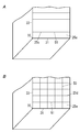
- FIG. 4 is an explanatory diagram showing a binary image captured by the imaging unit and binarized.
- FIG. 5 is an explanatory diagram showing a binary image corrected in the correction mode.
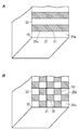
- FIG. 6A is an explanatory diagram illustrating a measurement image obtained by capturing an image of the object to be measured in the storage chamber with the imaging unit.
- FIG. 6B is an explanatory diagram showing a binary image in a state in which the object to be measured is arranged in the storage chamber.
- FIG. 1 is a perspective view showing a dimension measuring apparatus according to the first embodiment.
- FIG. 2 is a block diagram showing the same imaging unit and image processing unit.
- FIG. 3 is a flowchart of the correction mode of the dimension measurement method described above.
- FIG. 7 is a flowchart of the size measurement mode of the dimension measuring method.
- FIG. 8A is a side view of the first side portion of the binary image of FIG. 6B.
- FIG. 8B is a plan view of the lower surface portion of the binary image of FIG. 6B.
- FIG. 8C is a plan view of the lower surface portion of the binary image of FIG. 6B.
- FIG. 9 is a flowchart showing another example of the correction mode of the dimension measuring method.
- FIG. 10 is an explanatory diagram of a state in which the virtual line C obtained by translating the edge A13 is superimposed on the edge A16.
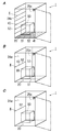
- FIG. 11A is a perspective view showing another example of the marker of the dimension measuring device.
- FIG. 11B is a perspective view showing another example of the marker of the dimension measuring device.
- FIG. 11A is a perspective view showing another example of the marker of the dimension measuring device.
- FIG. 11C is a perspective view showing another example of the marker of the dimension measuring device.
- FIG. 12 is a perspective view of a dimension measuring apparatus according to the second embodiment of the present invention.
- FIG. 13 is a block diagram illustrating an imaging unit and an image processing unit.
- FIG. 14 is a flowchart of the size measurement mode for measuring the size of the object to be measured.
- FIG. 15 is an explanatory diagram of an edge image created based on an image captured by the imaging unit.
- FIG. 16A is a perspective view showing still another example of the same dimension measuring apparatus.
- FIG. 16B is a perspective view showing still another example of the same dimension measuring apparatus.
- FIG. 16C is a perspective view showing still another example of the same dimension measuring apparatus.
- FIG. 17A is a perspective view showing a further application example of the same dimension measuring apparatus.
- FIG. 17B is a perspective view showing a further application example of the above-described dimension measuring apparatus.
- FIG. 18A is a perspective view showing a further application example of the above-described dimension measuring apparatus.
- FIG. 18B is a perspective view showing a further application example of the above-described dimension measuring apparatus.
- FIG. 19A is a perspective view showing a further application example of the above-described dimension measuring apparatus.
- FIG. 19B is a perspective view showing a further application example of the same dimension measuring apparatus.
- FIG. 20A is a perspective view showing a further application example of the above-described dimension measuring apparatus.
- FIG. 20B is a perspective view showing a further application example of the above-described dimension measuring apparatus.
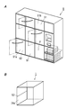
- FIG. 21A is a perspective view of a delivery box device equipped with the same dimension measuring device.
- FIG. 21B is a perspective view illustrating a dimension measuring device used in the
- the first embodiment relates to a dimension measuring apparatus and a dimension measuring method.
- image processing is performed on an image of a measurement object captured by the imaging unit, a rectangular parallelepiped storage chamber for storing an object to be measured such as a delivery product, an imaging unit fixed at one vertex of the upper surface of the storage chamber
- a dimension measuring device including an image processing unit to perform is known (for example, see Japanese Patent Application Laid-Open No. 2006-119792).
- the first embodiment aims to provide a dimension measuring apparatus that can accurately obtain the size of an object to be measured.
- the dimension measuring apparatus 101 measures the size of the measurement object 150 such as a delivery item.
- the size of the device under test 150 is the vertical, horizontal, and height dimensions of the device under test 150.
- the shape of the DUT 150 is a cube or a rectangular parallelepiped.
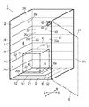
- the dimension measuring device 101 includes a storage chamber 111 as shown in FIG.
- the storage chamber 111 includes an outer body 1111 that forms an outer surface of the dimension measuring apparatus 101, and an internal space 1112 that is formed inside the outer body 1111.
- the shape of the outer body 1111 is a rectangular parallelepiped.
- the outer body 1111 has a lower wall part 120, a side wall part 121, and an upper wall part 125.
- the side wall 121 of the outer body 1111 is formed with an entrance / exit 1261 which is an opening for allowing the object 150 to be taken in and out of the internal space 1112.
- the side on which the entrance / exit 1261 is provided is the front F, and the opposite side is the rear B. Then, the right side R and the left side L are defined with reference to when the user stands toward the entrance / exit 1261 of the dimension measuring apparatus 101.
- the vertical dimension of the DUT 150 is the dimension of the DUT 150 in the front-rear direction.
- the horizontal dimension of the measurement object 150 is the horizontal dimension of the measurement object 150.
- the height dimension of the device under test 150 is the vertical dimension of the device under test 150.
- the lower wall portion 120 is formed in a rectangular shape when viewed from below.
- a surface on the inner space 1112 side (upper side) of the lower wall portion 120 is a lower surface portion 1201.
- An object to be measured 150 is placed on the lower surface portion 1201.
- the side wall 121 has a right wall 122, a left wall 123, and a rear wall 124.
- the right wall portion 122 extends upward from the right end portion of the lower wall portion 120.
- the left wall portion 123 extends upward from the left end portion of the lower wall portion 120.
- the rear wall portion 124 extends upward from the rear end portion of the lower wall portion 120.
- the right wall portion 122 is formed in a rectangular shape when viewed from the right side.
- a surface on the inner space 1112 side (left side) is a right surface portion 1221.
- the left wall 123 is formed in a rectangular shape when viewed from the left.
- a surface on the internal space 1112 side (right side) is a left surface portion 1231.
- the rear wall portion 124 is formed in a rectangular shape when viewed from the rear. In the rear wall portion 124, the inner space 1112 side (front side) surface is referred to as a rear surface portion 1241.
- the upper wall 125 is connected to the upper edge of the right wall 122, the upper edge of the left wall 123, and the upper edge of the rear wall 124.
- the upper wall portion 125 is formed in a rectangular shape as viewed from above.
- the inner space 1112 side (lower side) surface is referred to as an upper surface portion 1251.
- the outer body 1111 has a rectangular parallelepiped shape opened to the front F, and the opening to the front F is defined as an entrance / exit 1261.
- the outer body 1111 is provided with a door for opening and closing the entrance / exit 1261.
- the door is attached to the front end portion of the right wall portion 122 and rotates about the front end portion of the right wall portion 122 as a shaft 1262.
- the door is formed in a rectangular shape when viewed from the front in the closed state.
- the door constitutes the front wall portion 126 of the outer body 1111 in the closed state.
- a surface on the internal space 1112 side (rear side) is a front surface portion 1263.
- the interior space 1112 of the storage chamber 111 is formed by being surrounded by a lower surface portion 1201, a right surface portion 1221, a left surface portion 1231, a rear surface portion 1241, an upper surface portion 1251, and a front surface portion 1263.
- the internal space 1112 is formed in a rectangular parallelepiped shape.
- the rear surface portion 1241 is described as a first side surface portion 1242
- the left surface portion 1231 is described as a second side surface portion 1232.
- the outer body 1111 has a first corner 112 formed at a portion where the lower surface portion 1201 and the first side surface portion 1242 intersect.
- the outer body 1111 has a second corner 113 formed at a portion where the lower surface portion 1201 and the second side surface portion 1232 intersect.
- the outer body 1111 has a third corner 114 formed at a portion where the first side surface portion 1242 and the second side surface portion 1232 intersect.
- a portion where the first entering corner 112, the second entering corner 113, and the third entering corner 114 intersect with each other is defined as a reference corner 115.
- a reference point serving as a reference for placing the DUT 150 at a predetermined position is set in the reference corner 115.
- the measurement object 150 placed in alignment with the reference corner 115 comes into contact with the lower surface 1201, the first side surface 1242, and the second side surface 1232, so that the vertical position, the horizontal position, and the height are measured. Positioning is performed.
- the position of the object 150 to be measured is a predetermined position of the object 150 to be measured.
- a marker 116 is provided on the inner surface of the storage chamber 111 as shown in FIG.
- the marker 116 is provided on the first side surface portion 1242, the second side surface portion 1232, and the lower surface portion 1201.
- the marker 116 provided on the first side surface portion 1242 is referred to as a first marker 1161
- the marker 116 provided on the second side surface portion 1232 is referred to as a second marker 1162
- the marker 116 provided on the lower surface portion 1201 is referred to as a third marker 1163.
- the marker 116 has a rectangular frame shape.
- the first marker 1161 is drawn along a line along the third corner 114, and a line parallel to the first corner 112 is drawn from each of the upper end portion and the lower end portion thereof. A line connecting the right ends is drawn.
- the second marker 1162 is drawn along a line along the third entering corner 114, and a line parallel to the second entering corner 113 is drawn from each of the upper end portion and the lower end portion thereof. A line connecting the front ends is drawn.
- the third marker 1163 is drawn along the first entering corner 112, and a line parallel to the second entering corner 113 is drawn from each of the left end and the right end thereof, and the front end of each line. A line connecting the two is drawn.
- the first marker 1161, the second marker 1162, and the third marker 1163 of the first embodiment have the same color tone, but it is preferable that the color tones are different from each other.
- the color tone means color tone such as lightness and saturation of the color.
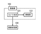
- the dimension measuring apparatus 101 is provided with an imaging unit 103 in a storage chamber 111.
- the imaging unit 103 is disposed at a position where the entire interior of the storage chamber 111 can be imaged.
- the imaging unit 103 is installed at a corner formed by the upper surface portion 1251, the right surface portion 1221, and the front surface portion 1263 which are diagonal to the reference corner portion 115.
- the imaging unit 103 includes a camera body 131 and a lighting tool 132.
- the camera body 131 a camera capable of imaging the entire interior of the storage chamber 111 is used.
- the camera body 131 is a camera that can image the entire object to be measured 150, the lower surface portion 1201, the first side surface portion 1242, and the second side surface portion 1232.
- a CCD (Charge-Coupled Device) camera is used as the camera body 131.
- a wide-angle lens is used so that the entire interior of the storage chamber 111 can be easily photographed.
- the illuminator 132 is electrically connected to the control unit of the camera body 131.
- the lighting tool 132 brightens the inside of the storage chamber 111.
- the illuminator 132 includes an object to be measured 150, a first entry corner 112, a second entry corner 113, a third entry corner 114, a first marker 1161, a second marker 1162, and a third marker 1163 on the camera body 131.
- White LED Light Emitting Diode is used for the lighting device 132.
- the dimension measuring apparatus 101 includes an image processing unit 104 as shown in FIG.
- the image processing unit 104 includes a microcomputer.
- the microcomputer has a CPU (Central Processing Unit), a memory, and the like.
- the microcomputer performs control by the CPU executing a program stored in the memory.
- the image processing unit 104 performs image processing on the image captured by the imaging unit 103. Further, the image processing unit 104 has a correction mode 141 having a program for correcting an image of the device under test 150 stored in the memory.
- the image processing unit 104 causes the imaging unit 103 to image the lower surface part 1201, the first side surface part 1242, the second side surface part 1232, and the marker 116 before the DUT 150 is placed in the storage chamber 111. Get the original image. Based on this original image, the correction mode 141 shown in FIG. 3 is started in step S101.
- noise is removed from the original image (grayscale image) in step S102. Then, filtering is performed based on the luminance value which is one piece of information of the image from which noise has been removed.
- the correction mode 141 detects an edge by performing binarization on the image on which the filter processing has been performed in step S103.
- An image subjected to such processing is referred to as a binary image 142 (see FIG. 4).
- the binary image 142 is a two-dimensional image. Data of the binary image 142 is stored in the memory of the image processing unit 104.
- step S104 the marker 116 in the binary image 142 is identified by pattern matching based on the shape and luminance value information of the marker 116 acquired in advance.
- the first side surface portion 1242, the second side surface portion 1232, and the lower surface portion 1201 in the binary image 142 are identified from the first marker 1161, the second marker 1162, and the third marker 1163 identified in step S105. Identify edges.
- the edges A11 to A19 in the binary image 142 are identified.
- the correction mode 141 includes internal parameters including optical axis center coordinates, focal length, lens distortion coefficient, and the like that relate the coordinates of the binary image 142 before distortion correction and the binary image 142 after distortion correction. adjust.
- the internal parameter for example, the position of the intersection of the checkerboard pattern in the checkerboard photographed image whose grid size is known is detected, and the internal parameter is calculated so that the intervals of the intersection are equal.
- the correction mode in step S ⁇ b> 16, the previously determined internal parameters are used for the storage chamber 111 having a known size and further adjusted to be optimal for the storage chamber 111. In this case, the internal parameter is distortion correction data.
- step S107 the distortion of the edges A11 to A19 is corrected using the internal parameters, and the edges A11 to A19 are linearized to obtain the corrected binary image 142 shown in FIG.
- a known method using an internal parameter for example, Japanese Patent Laid-Open No. 2015-35685
- another known method for example, Japanese Patent Laid-Open No. 2011-25428 described later
- Publication may be used.
- the measurement object 150 is disposed at a predetermined position in the storage chamber 111, and the lower surface portion 1201, the first side surface portion 1242, the second side surface portion 1232, the marker 116, and the object to be measured.
- An image for measurement is acquired by causing the imaging unit 103 to image the measurement object 150.
- the correction mode 141 acquires a binary image 142 as shown in FIG. 6A by performing noise removal, filtering, and binarization on the measurement image.
- step S19 the distortions of the edges A11 to A19 and the edges T1 to T8 of the DUT 150 are corrected using internal parameters (distortion correction data).
- the correction mode 141 acquires the corrected image 144 shown in FIG. 6B in which the edges A11 to A19 and the edges T1 to T8 in the measurement image are corrected.
- image processing is performed on the binary image 142 corrected in the correction mode 141, and a size measurement mode 143 for measuring the size of the object 150 shown in FIG. 7 is performed.
- the size measurement mode 143 the first side surface portion 1242 of the corrected binary image 142 in which the measurement object 150 is arranged as shown in FIG. A side view (see FIG. 8A) viewed from the right front is obtained. Further, the size measurement mode 143 includes a first plan view (see FIG. 8B) of the lower surface 1201 of the corrected binary image 142 viewed from above, and a second view of the lower surface 1201 of the corrected binary image 142 viewed from above. A plan view (see FIG. 8C) is obtained.
- step S113 the pixels arranged along the length direction of the edge A13 in the side view are scanned.
- a first change amount H1 which is a difference between the length based on the number of pixels from the edge A19 to the edge T8 and the length based on the number of pixels from the edge A19 to the edge A12 is obtained.
- the size measurement mode 143 also scans pixels arranged along the length direction of the edge A12 in the first plan view. At this time, as shown in FIG. 8B, a second change amount H2 that is a difference between the length based on the number of pixels from the edge A15 to the edge T5 and the length based on the number of pixels from the edge A15 to the edge A11 is obtained.
- a third change amount H3 which is the difference between the length based on the number of pixels from edge A14 to edge T4 and the length based on the number of pixels from edge A14 to edge A12, is obtained.
- step S114 shown in FIG. 7 from the ratio between the length based on the number of pixels of the edge A13 in the corrected binary image 142 shown in FIG.
- the height of the measurement object 150 is obtained based on the one change amount H1.
- the vertical length of the device under test 150 is obtained based on the second change amount H2
- the horizontal length of the device under test 150 is obtained based on the third change amount H3.
- step S116 to step S120 are the same as step S101 to step S105 described above, and thus description thereof is omitted.
- the edges A11 to A19 and the straight lines corresponding to the edges A11 to A19 are compared to determine the distortion amount Y for the straight lines.
- the amount of distortion Y is obtained by superimposing a straight virtual line C on the edge A16 (see FIG. 10).
- the correction mode 141 obtains a correction coefficient K that makes the edge A16 a straight line based on the distortion amount Y.
- the same operation is performed for the other edges, and the respective correction coefficients K are obtained.
- the corrected binary image 142 shown in FIG. 6B is obtained by correcting the distortion of the edges A11 to A19 from the respective correction coefficients K and making the edges A11 to A19 linear in step S123. .
- the correction coefficient K becomes distortion correction data.
- edges identified by the image processing unit 104 are straight lines that are not easily distorted even when the imaging unit 103 captures images using a wide-angle lens.
- the distortion amount Y may be obtained by using this.
- step S124 the measured object 150 is disposed at a predetermined position in the storage chamber 111, and the lower surface portion 1201, the first side surface portion 1242, the second side surface portion 1232, the marker 116, and the object to be measured.
- the measurement object shown in FIG. 6A is acquired by causing the imaging unit 103 to image the measurement object 150.
- the correction mode 141 uses the correction coefficient K (distortion correction data) in step S125 to correct the distortion of the edges A11 to A19 and the edges T1 to T8 of the DUT 150 as shown in FIG. 6B.
- Edges A11 to A19 are corrected with a correction coefficient K corresponding to each.
- the correction coefficient K of the edge T1 is obtained by regarding the positional relationship of the edge T1 with respect to the edges A13 and A16 and the correction coefficient K of the edge A13 and the correction coefficient K of the edge A16 as a proportional relationship.
- the correction coefficient K is determined based on the positional relationship with respect to two of the edges A11 to A19.
- the method of determining the correction coefficients for the edges T1 to T8 is not limited to the method described above.
- the configuration of the dimension measuring apparatus 101 of the first embodiment is not limited to the above-described one aspect, and may be the following aspect.
- noise removal of an image captured by the imaging unit 103 may be performed by a moving average filter or a median filter.
- a Sobel filter or a Prewitt filter is used as a primary difference operator.
- a secondary difference operator may be used.
- the binarization of the filtered image may be binarization using a moving average method or binarization using two threshold values.
- the shape of the marker 116 is not limited to a circular shape or a rectangular shape, and may be another polygonal shape.
- the shape of the object to be measured 150 is not limited to a cube or a rectangular parallelepiped, and the shape of the three surfaces imaged by the imaging unit 103 may be substantially rectangular.
- the shape of the outer body 1111 is a rectangular parallelepiped, but may be a cube, and the shape is not limited. Moreover, the shape which has a protrusion partially may be sufficient.
- the shape of the internal space 1112 is a rectangular parallelepiped, but may be a cube, and the shape is not limited.
- the reference corner 115 may be any one of four corners formed by the lower surface 1201, the right surface 1221, the left surface 1231, the rear surface 1241, and the front surface 1263.
- the camera body 131 may be a CMOS (Complementary Metal Metal Oxide Semiconductor) camera.
- CMOS Complementary Metal Metal Oxide Semiconductor
- an image to be captured may be grayscale or color.
- the image picked up by the image pickup unit 103 is color, it is preferable to convert the image into a grayscale image when performing image processing.
- the control unit of the camera body 131 and the illumination tool 132 are connected, and ON / OFF of the illumination tool 132 is operated by the control unit of the camera body 131, but the illumination tool 132 and the image processing unit 104 are operated. And the lighting device 132 may be operated by the image processing unit 104.
- control unit of the camera body 131 and the illumination tool 132 may be connected wirelessly.
- the camera body 131 and the illumination tool 132 may be provided separately.
- Fluorescent lamps, light bulbs, and other color LEDs may be used for the lighting fixture 132.
- the lighting device 132 preferably has a color or brightness that allows the image processing unit 104 to easily detect an edge of an image captured by the camera body 131.
- the edges A11 to A19 corresponding to the sides of the lower surface portion 1201, the first side surface portion 1242, and the second side surface portion 1232 in the binary image 142 can be easily identified. . This facilitates the processing for correcting the distortion of the edges A11 to A19 and the edges T1 to T8 in the binary image 142, so that the measurement of the size of the object 150 can be accelerated.
- the edges A11 to A19 corresponding to the sides of the lower surface portion 1201, the first side surface portion 1242, and the second side surface portion 1232 are further identified. It becomes easy to do.
- the dimension measuring apparatus 101 has the following configuration.
- the dimension measuring apparatus 101 of the first embodiment has the following first feature.
- the dimension measuring apparatus 101 includes a storage chamber 111 in which the measurement target 150 is detachably stored, and an imaging unit that is provided in the storage chamber 111 and images the measurement target 150 stored in the storage chamber 111.
- the dimension measuring apparatus 101 includes an image processing unit 104 that performs image processing based on information on an image captured by the imaging unit 103 and measures the size of the measurement object 150.
- the storage chamber 111 has a rectangular lower surface portion 1201 on which the object 150 to be measured is placed, a rectangular first side surface portion 1242 extending upward from the lower surface portion 1201, and an upper surface extending from the lower surface portion 1201. And a rectangular second side surface portion 1232 adjacent to the first side surface portion 1242.
- the storage chamber 111 includes a first corner 112 formed by the lower surface portion 1201 and the first side surface portion 1242, a second corner 113 formed by the lower surface portion 1201 and the second side surface portion 1232, and a first side surface portion 1242. And a third entering corner 114 formed by the second side surface portion 1232.
- the storage chamber 111 is formed at a portion where the first entering corner 112, the second entering corner 113, and the third entering corner 114 intersect, and has a reference corner 115 serving as a reference point at which the DUT 150 is arranged at a predetermined position.
- the storage chamber 111 includes a marker 116 that displays the positions of the sides of the first side surface portion 1242, the second side surface portion 1232, and the lower surface portion 1201.
- the distortion in the binary image 142 can be easily corrected by using the marker 116.
- the dimension measuring apparatus 101 having the first feature has the following additional second feature.
- the markers 116 are lines, circles or polygons.
- the marker 116 can be configured easily.
- the dimension measuring apparatus 101 having the first or second feature has the following additional third feature.
- the markers 116 provided on different surfaces have different colors.
- the edges A11 to A19 corresponding to the sides of the first side surface portion 1242, the second side surface portion 1232, and the lower surface portion 1201 in the binary image 142 can be easily identified.
- the dimension measuring apparatus 101 having the first to third features has the following additional fourth feature.
- the storage chamber 111 is opposed to the rectangular upper surface portion 1251 extending from the upper edges of the first side surface portion 1242 and the second side surface portion 1232 and the first side surface portion 1242, and the object 150 to be measured And an entrance / exit 1261 for taking in and out the door.
- the imaging unit 103 is provided at the end of the upper surface 1251 opposite to the reference corner 115 at the end of the entrance / exit 1261.
- the imaging unit 103 can easily capture the entire lower surface portion 1201, the first side surface portion 1242, the second side surface portion 1232, the measured object 150, and the marker 116.
- the dimension measuring apparatus 101 having the first to fourth characteristics has the following additional fifth characteristics.
- the imaging unit 103 includes a lighting device 132 that illuminates the storage chamber 111.
- the dimension measuring apparatus 101 having the fifth feature, even if the amount of light in the storage chamber 111 is insufficient, the shortage of light amount can be resolved by illuminating the interior of the storage chamber 111 with the illumination tool 132.
- the dimension measuring apparatus 101 having the first to fifth features has the following additional sixth feature.
- the object 150 to be measured is disposed at the back corner of the lower surface portion 1201.
- the imaging unit 103 can easily capture the entire measured object 150.
- the dimension measuring method of the first embodiment has the following configuration.
- the dimension measuring method of the first embodiment has the following sixth feature.
- a storage chamber 111 in which the object to be measured 150 is freely inserted and removed an imaging unit 103 that is provided in the storage chamber 111 and images the object 150 to be stored in the storage chamber 111, and the imaging unit 103
- An image processing unit 104 that performs image processing based on the information of the image captured in step S ⁇ b> 1 and measures the size of the DUT 150 is used.
- the storage chamber 111 has a rectangular lower surface portion 1201 on which the object 150 to be measured is placed, a rectangular first side surface portion 1242 extending upward from the lower surface portion 1201, and an upper surface extending from the lower surface portion 1201. And a rectangular second side surface portion 1232 adjacent to the first side surface portion 1242.
- the storage chamber 111 includes a first corner 112 formed by the lower surface portion 1201 and the first side surface portion 1242, a second corner 113 formed by the lower surface portion 1201 and the second side surface portion 1232, and a first side surface portion 1242. And a third entering corner 114 formed by the second side surface portion 1232.
- the storage chamber 111 is formed at a portion where the first entering corner 112, the second entering corner 113, and the third entering corner 114 intersect, and has a reference corner 115 serving as a reference point at which the DUT 150 is arranged at a predetermined position.
- the storage chamber 111 includes a marker 116 that displays the positions of the sides of the first side surface portion 1242, the second side surface portion 1232, and the lower surface portion 1201.
- the image processing unit 104 creates a binary image 142 by binarizing the image captured by the imaging unit 103 in a state before the DUT 150 is placed in the storage chamber 111.
- the image processing unit 104 identifies the markers 116 in the binary image 142, and the edges A11 to A11 corresponding to the sides of the first side surface portion 1242, the second side surface portion 1232, and the lower surface portion 1201 in the binary image 142 from the marker 116.
- A19 is identified, and distortion correction data is created based on the distortion of the edges A11 to A19.
- the image processing unit 104 creates a binary image 142 by binarizing the image picked up by the image pickup unit 103 in a state where the DUT 150 is placed in the storage chamber 111.
- the image processing unit 104 obtains the corrected image 144 by correcting the distortion of the edges T1 to T8 of the device under test 150 identified in the binary image 142 based on the distortion correction data.
- the image processing unit 104 measures the size of the object to be measured 150 by scanning the surface corresponding to the first side surface portion 1242, the second side surface portion 1232, and the lower surface portion 1201 of the corrected image 144.
- the distortion in the binary image 142 can be easily corrected by using the marker 116.
- the dimension measuring method having the sixth feature has the following additional seventh feature.
- the storage chamber 111 faces the rectangular upper surface portion 1251 extending from the upper edges of the first side surface portion 1242 and the second side surface portion 1232, and the first side surface portion 1242, and the DUT 150 And an entrance / exit 1261 for taking in and out the door.
- the imaging unit 103 is provided at the end of the upper surface 1251 opposite to the reference corner 115 at the end of the entrance / exit 1261.
- the imaging unit 103 can easily capture the entire bottom surface 1201, the first side surface 1242, the second side surface 1232, the DUT 150, and the marker 116.
- the marker 116 provided in the dimension measuring apparatus 101 of the first embodiment described above may be in a mode as shown in FIGS. 11A to 11C, for example (this is another example).
- the dimension measuring apparatus 101 of this other example particularly relates to the shape of the marker 116.
- a plurality of markers 116 may be provided on the inner surface of the storage chamber 111 as shown in FIG. 11A.
- the marker 116 has a circular shape.
- a plurality of first markers 1161 are provided on the first side surface portion 1242.
- the first markers 1161 are provided at the four corners of the first side surface portion 1242.
- the second markers 1162 are provided at the four corners of the second side surface portion 1232.
- the third markers 1163 are provided at the four corners of the lower surface part 1201.
- a plurality of markers 116 may be provided on the inner surface of the storage chamber 111 as shown in FIG. 11B.
- the marker 116 has a circular shape, but unlike FIG. 9A, the third marker 1163 provided at the four corners of the lower surface 1201 is not colored.
- a plurality of markers 116 may be provided on the inner surface of the storage chamber 111 as shown in FIG. 11C.
- the marker 116 has a circular shape.
- the first marker 1161 is provided at both end portions of the first side surface portion 1242 opposite to the third entering corner 114.
- the second marker 1162 is provided at both end portions of the end portion of the second side surface portion 1232 opposite to the third entering corner 114.
- the third marker 1163 is not provided on the lower surface portion 1201.
- the marker 116 may be a polygonal shape including a triangular shape as shown in FIG. 11D.
- the marker 116 may be a recess formed on the inner surface of the storage chamber 111 as shown in FIG. 11E.
- the marker 116 may be a convex portion formed on the inner surface of the storage chamber 111 as shown in FIG. 11F.
- the second embodiment of the present invention described below particularly relates to a dimension measuring apparatus that measures the size of an object to be measured based on an image captured by an imaging unit, and a home delivery box apparatus including the dimension measuring apparatus.
- the dimension measuring apparatus 1 measures the size of the object 80 to be measured.
- the size of the device under test 80 is the vertical, horizontal, and height dimensions of the device under test 80.
- the shape of the DUT 80 is a cube or a rectangular parallelepiped.
- the dimension measuring device 1 includes a storage chamber 11 as shown in FIG.
- the storage chamber 11 includes an outer body 2 that constitutes an outer shell of the dimension measuring device 1 and an internal space 10 that is formed inside the outer body 2.
- the shape of the outer body 2 is a rectangular parallelepiped.
- the outer body 2 has a lower wall portion 21, a side wall portion 22, and an upper wall portion 26.
- an entrance / exit 12 that is an opening for allowing the object 80 to be taken in and out of the internal space 10 is formed.
- the side where the doorway 12 is provided is the front F, and the opposite side is the rear B. Then, the right side R and the left side L are defined with reference to the time when the user stands toward the entrance / exit 12 of the dimension measuring device 1.
- the vertical dimension of the DUT 80 is the dimension of the DUT 80 in the front-rear direction.
- the horizontal dimension of the measurement object 80 is the horizontal dimension of the measurement object 80.
- the height dimension of the DUT 80 is the vertical dimension of the DUT 80.
- the lower wall portion 21 is formed in a rectangular shape when viewed from below.
- a surface on the inner space 10 side (upper side) of the lower wall portion 21 is a lower surface portion 20.
- An object 80 to be measured is placed on the lower surface portion 20.
- the side wall part 22 has a right wall part 23, a left wall part 24 and a rear wall part 25.
- the right wall portion 23 extends upward from the right end portion of the lower wall portion 21.
- the left wall portion 24 extends upward from the left end portion of the lower wall portion 21.
- the rear wall portion 25 extends upward from the rear end portion of the lower wall portion 21.
- the right wall portion 23 is formed in a rectangular shape when viewed from the right side.
- the surface on the inner space 10 side (left side) is defined as a right surface portion 23a.
- the left wall portion 24 is formed in a rectangular shape when viewed from the left.
- the surface on the inner space 10 side (right side) is defined as a left surface portion 24b.
- the rear wall portion 25 is formed in a rectangular shape when viewed from the rear.
- the surface on the internal space 10 side (front side) is defined as a rear surface portion 25b.
- the upper wall portion 26 is connected to the upper edge portion of the right wall portion 23, the upper edge portion of the left wall portion 24, and the upper edge portion of the rear wall portion 25.
- the upper wall portion 26 is formed in a rectangular shape as viewed from above.
- the surface on the inner space 10 side (lower side) is defined as an upper surface portion 26a.
- the outer body 2 has a rectangular parallelepiped shape opened to the front, and the front opening is defined as the entrance 12.
- the outer body 2 is provided with a door 13 for opening and closing the entrance 12.
- the door 13 is attached to the front end portion of the right wall portion 23 and rotates around the front end portion of the right wall portion 23 as an axis.
- the door 13 is formed in a rectangular shape when viewed from the front in the closed state. Further, the door 13 constitutes a front wall portion 27 of the outer body 2 in a closed state.
- the surface on the internal space 10 side (rear side) is defined as a front surface portion 27a.
- the inner space 10 of the storage chamber 11 is formed by being surrounded by a lower surface portion 20, a right surface portion 23a, a left surface portion 24b, a rear surface portion 25b, an upper surface portion 26a, and a front surface portion 27a.
- the internal space 10 is formed in a rectangular parallelepiped shape.
- a reference point serving as a reference for placing the object 80 to be measured at a predetermined position is set.
- the reference point of the second embodiment is a left back corner formed by the lower surface portion 20, the rear surface portion 25b, and the left surface portion 24b.
- the side where the rear surface part 25b is provided is the first side 20a
- the side where the left surface part 24b is provided is the second side 20b.
- the first side 20a and the second side 20b are linear.
- the first side 20a and the second side 20b are orthogonal to each other.
- the rear surface portion 25b is described as a first side surface portion 25a
- the left surface portion 24b is described as a second side surface portion 24a.
- the outer body 2 has a first corner 31 formed at a portion where the lower surface portion 20 and the first side surface portion 25a intersect each other.
- the outer body 2 has a second corner 32 formed at a portion where the lower surface portion 20 and the second side surface portion 24a intersect each other.
- the outer body 2 has a third corner 33 formed at a portion where the first side surface portion 25a and the second side surface portion 24a intersect each other.
- a portion where the first entering corner 31, the second entering corner 32, and the third entering corner 33 intersect is defined as a reference corner portion 30.
- the measurement object 80 placed in alignment with the reference corner 30 comes into contact with the lower surface portion 20, the first side surface portion 25 a, and the second side surface portion 24 a, so that the vertical position, the horizontal position, and the height are measured. Positioning is performed.
- the position of the object 80 to be measured is a predetermined position of the object 80 to be measured.
- a reference line 4 is drawn as a reference for measuring the object 80 to be measured arranged at a predetermined position.
- a straight line such as a third line 53 (see FIG. 19B) parallel to the direction is used.
- the reference line 4 functions as a marker that displays the positions of the sides of the first side surface portion 25a, the second side surface portion 24a, and the lower surface portion 20.
- the first line 51 is drawn to either one or both of the lower surface portion 20 and the first side surface portion 25a.
- the first line 51 When the first line 51 is drawn to the lower surface portion 20, the first line 51 extends rightward from the second corner 32.
- the first line 51 is arranged at a predetermined distance forward from the first corner 31. Further, a color different from that of the lower surface portion 20 is used for the first line 51.
- the color of the first line 51 is a color whose luminance value is far from the luminance value of the lower surface portion 20.
- the first line 51 When the first line 51 is drawn to the first side surface portion 25a, the first line 51 extends rightward from the third corner 33.
- the first line 51 is disposed at a predetermined distance upward from the first corner 31.
- a color different from the color of the surface of the first side surface portion 25a is used for the first line 51.
- a color whose luminance value is far from the luminance value of the color of the surface of the first side surface portion 25a is used for the color of the first line 51.
- the second line 52 is drawn to either one or both of the lower surface portion 20 and the second side surface portion 24a.
- the second line 52 extends forward from the first corner 31 when drawn to the lower surface portion 20.
- the second line 52 is arranged at a predetermined distance from the second corner 32 to the right. Further, a color different from that of the lower surface portion 20 is used for the second line 52. In particular, as the color of the second line 52, a color whose luminance value is far from the luminance value of the lower surface portion 20 is used.
- the second line 52 When the second line 52 is pulled by the second side surface portion 24a, the second line 52 extends forward from the third corner 33.
- the second line 52 is disposed at a predetermined distance upward from the second entering corner 32. Further, a color different from the color of the surface of the second side surface portion 24a is used for the second line 52.
- the color of the second line 52 is a color whose luminance value is far from the luminance value of the surface color of the second side surface portion 24a.
- the third line 53 is drawn to either one or both of the first side surface portion 25a and the second side surface portion 24a.
- the third line 53 extends upward from the first corner 31 when pulled by the first side face portion 25a.
- the third line 53 is arranged at a predetermined distance from the third corner 33 to the right.
- the third line 53 uses a color different from that of the first side surface portion 25a.
- the color of the third line 53 is a color whose luminance value is far from the luminance value of the first side surface portion 25a.
- the third line 53 extends upward from the second corner 32 when drawn to the second side surface portion 24a.
- the third line 53 is arranged with a predetermined distance forward from the third corner 33.
- a color different from the color of the surface of the third side surface portion is used for the third line 53.
- a color whose luminance value is far from the luminance value of the surface color of the second side surface portion 24a is used for the color of the third line 53.
- a solid line is preferably used as the line type of the reference line 4.
- a reference line 4 (hereinafter referred to as a first reference line 41) is drawn on the lower surface portion 20, as shown in FIG.
- the first reference line 41 is L-shaped when viewed from above.
- the first reference line 41 is a line obtained by combining the first line 51 and the second line 52. In the first reference line 41, the first line 51 and the second line 52 intersect at a right angle.
- a plurality of first reference lines 41 are drawn on the lower surface portion 20.
- five first reference lines 41 are drawn on the lower surface portion 20.
- the plurality of first reference lines 41 are arranged at equal intervals.
- the first lines 51 of the first reference line 41 of the second embodiment are arranged at equal intervals forward from the reference corner 30.
- the first lines 51 of the plurality of first reference lines 41 are arranged at an interval of 5 cm.
- Table 1 shows the relationship between the order from the reference corner 30 of the first line 51 of the first reference line 41 and the distance from the first corner 31 at that position.
- the second lines 52 of the first reference line 41 of the second embodiment are arranged at equal intervals from the reference corner 30 to the right.
- the second lines 52 of the plurality of first reference lines 41 are arranged at intervals of 5 cm.
- Table 2 shows the relationship between the order from the reference corner 30 of the second line 52 of the first reference line 41 and the distance from the second entering corner 32 at that position.
- a reference line 4 (hereinafter referred to as a second reference line 42) is drawn on the first side face portion 25a.
- the second reference line 42 is the first line 51.
- a plurality of second reference lines 42 are drawn on the first side surface portion 25a.
- six second reference lines 42 are drawn on the first side surface portion 25a.
- the plurality of second reference lines 42 are arranged at equal intervals.
- the second reference lines 42 of the second embodiment are arranged at equal intervals upward from the reference corner 30.
- the plurality of second reference lines 42 are arranged at intervals of 5 cm.
- Table 3 shows the relationship between the order from the reference corner 30 of the second reference line 42 and the distance from the first corner 31 at that position.
- a reference line 4 (hereinafter referred to as a third reference line 43) is drawn on the second side surface portion 24a.
- the third reference line 43 is the second line 52.
- a plurality of third reference lines 43 are drawn on the second side surface portion 24a.
- six third reference lines 43 are drawn on the second side surface portion 24a.
- the plurality of third reference lines 43 are arranged at equal intervals.
- the third reference lines 43 of the second embodiment are arranged at equal intervals upward from the reference corner 30.
- the plurality of third reference lines 43 are arranged at intervals of 5 cm.
- Table 4 shows the relationship between the order of the third reference line 43 from the reference corner 30 and the distance from the second corner 32 at that position.
- the first line 51 and the second line 52 among the first line 51, the second line 52, and the third line 53 are used in the storage chamber 11 of the second embodiment. Yes.
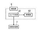
- the dimension measuring apparatus 1 is provided with an imaging unit 6 in the storage chamber 11.
- the imaging unit 6 is disposed at a position where the entire interior of the storage chamber 11 can be imaged.
- the imaging unit 6 is installed at a corner formed by the upper surface portion 26a, the right surface portion 23a, and the front surface portion 27a.
- the imaging unit 6 includes a camera body 61 and a lighting tool 62 as shown in FIGS.
- the camera body 61 is a camera that can image the entire interior of the storage chamber 11.
- the camera body 61 is a camera that can image the entire object 80, the lower surface portion 20, the first side surface portion 25a, and the second side surface portion 24a.
- the camera body 61 is a CCD (Charge-Coupled Device) camera.
- a wide-angle lens is used so that the entire interior of the storage chamber 11 can be easily photographed.
- the illuminator 62 is electrically connected to the control unit of the camera body 61.
- the lighting tool 62 brightens the inside of the storage chamber 11.
- the illuminator 62 includes a device under test 80, a first entry corner 31, a second entry corner 32, a third entry corner 33, a first line 51, a second line 52, and a third line 53. It is used for causing the main body 61 to clearly capture an image.
- a white LED Light Emitting Diode
- the dimension measuring apparatus 1 has an image processing unit 7 as shown in FIG.
- the image processing unit 7 includes a microcomputer.
- the microcomputer has a CPU (Central Processing Unit), a memory, and the like.
- the microcomputer performs control by the CPU executing a program stored in the memory.
- the image processing unit 7 image processing is performed on the image captured by the imaging unit 6.
- the image processing unit 7 also has a size measurement mode 71 having a program for obtaining the size of the device under test 80 stored in the memory.
- the edges and vertices of the image captured by the imaging unit 6 are detected, and the vertical, horizontal, and height dimensions of the DUT 80 are obtained based on the detected edges and vertices.
- the data in Table 1, the data in Table 2, the data in Table 3, and the data in Table 4 are written in advance in the memory of the image processing unit 7 by the designer.
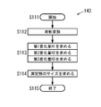
- the size measurement mode 71 is started in step S1.
- step S2 the lighting fixture 62 is turned on to adjust the brightness of the storage chamber 11.
- step S ⁇ b> 3 the imaging unit 6 is caused to image the inside of the storage chamber 11, thereby acquiring an image in which the inner surface of the storage chamber 11 and the measurement object 80 are captured.
- step S4 noise removal is performed on the captured image (grayscale image). Then, filtering is performed based on the luminance value, which is one piece of information of the image from which noise has been removed, to detect edges.
- step S4 the binarization is performed on the filtered image, so that the edge becomes clear.
- An image subjected to such processing is defined as an edge image 60 (see FIG. 15).
- the edge image 60 is a two-dimensional image.
- the data of the edge image 60 is stored in the memory of the image processing unit 7.
- step S5 edges and vertices of the measurement object 80 on the image are detected from the edge image 60 shown in FIG.
- the edge and vertex detection method will be described.
- the upper side of the imaging unit 6 is upward and the lower side is downward with respect to the state in which the imaging unit 6 is opposed to the measurement object 80 and the measurement object 80 is viewed from the imaging unit 6.
- the right side is defined as the right direction and the left side as the left direction.
- step S5 a polygon (hexagon) surrounded by six edges is detected in the edge image 60.
- step S5 a hexagon in which each edge extending from three vertices of six hexagonal vertices intersects at one point is detected from the detected hexagons.
- An object 80 to be measured on the edge image 60 is represented by six edges constituting the hexagon and three edges extending from three vertices.
- step S5 the six edges constituting the hexagon are changed to the edge E1, the edge E2, the edge E3, the edge E4, the edge E5, and the edge E6 in the clockwise direction from the upper right edge.
- the intersection of the edge E1 and the edge E2 is the vertex P1
- the intersection of the edge E2 and the edge E3 is the vertex P2
- the intersection of the edge E3 and the edge E4 is the vertex P3.
- the intersection of the edge E4 and the edge E5 is the vertex P4
- the intersection of the edge E5 and the edge E6 is the vertex P5
- the intersection of the edge E6 and the edge E1 is the vertex P6.
- step S5 the intersection point of the edge E7 extending from the vertex P1, the edge E8 extending from the vertex P3, and the edge E9 extending from the vertex P5 is set as the vertex P0.
- step S6 vertices and edges of the outer body 2 are detected from the edge image 60 shown in FIG.
- step S6 an edge A1 extending obliquely downward to the right from the vertex P2 is detected as the edge of the outer body 2.
- step S6 an edge A2 extending obliquely downward to the left from the vertex P4 is detected as the edge of the outer body 2.
- step S6 an edge A3 extending upward from the vertex P6 is detected as the edge of the outer body 2.
- step S6 the end of the outer body 2 opposite to the vertex P2 in the edge A1 is set as the vertex S1.
- step 6 the end of the outer body 2 opposite to the vertex P4 at the edge A2 is set as the vertex S2.
- step 6 the end of the outer body 2 opposite to the vertex P6 at the edge A3 is set as the vertex S3.
- step S6 the intersection of the edge A4 extending diagonally downward to the left from the vertex S1 and the edge A5 extending diagonally downward to the right from the vertex S2 as the vertex of the outer body 2 is defined as the vertex S4.
- step S6 the end on the opposite side to the vertex S1 of the edge A6 extending upward from the vertex S1 as the vertex of the outer body 2 is detected as the vertex S5.
- step 6 the end of the edge A7 that extends upward from the vertex S2 as the vertex of the outer body 2 is the vertex S6 opposite to the vertex S1.
- step S6 the edge from the vertex S5 to the vertex S3 is detected as the edge A8 as the edge of the outer body 2.
- step S6 the edge from the vertex S6 to the vertex S3 is detected as the edge A9 as the edge of the outer body 2.
- step S7 the edge of the reference line 4 is detected from the edge image 60 shown in FIG.
- step S7 as an edge of the reference line 4, an edge L1 parallel to the edge A1 is detected at edges other than the edges E1 to E9 and the edges A1 to A9.
- step S7 as an edge of the reference line 4, an edge L2 parallel to the edge A2 is detected at edges other than the edges E1 to E9 and the edges A1 to A9.
- step S8 the vertical dimension of the DUT 80 is obtained from the detection result based on the edge image 60 and the data shown in Table 1.
- step S8 it is detected that the vertex P4 is located between the third edge L1 and the fourth edge L1 from the vertex S2 in the plurality of edges L1 between the edge A1 and the edge A5. From this detection result and the data of the order of the first line 51 in Table 1, it is determined in step S8 that the vertex P2 is located between the second edge L1 and the third edge L1 from the reference corner 30. .
- step S8 based on Table 1, the vertical dimension of the DUT 80 is determined to be in the range of 10 to 15 cm.
- step S9 the horizontal dimension of the DUT 80 is obtained from the detection result based on the edge image 60 and the data in Table 2.
- step S9 it is detected that the vertex P2 is located between the third edge L2 and the fourth edge L2 from the vertex S1 in the plurality of edges L2 between the edge A2 and the edge A4. From this detection result and the data of the order of the second line 52 in Table 2, in step S9, it is determined that the vertex P2 is located between the second edge L2 and the third edge L2 from the reference corner 30. .
- step S9 based on Table 2, the horizontal dimension of the DUT 80 is determined to be in the range of 10 to 15 cm.
- step S10 the height dimension of the measurement object 80 is obtained from the detection result based on the edge image 60 and the data in Table 3.
- step S10 it is detected that the vertex P6 is located between the fourth edge L1 and the fifth edge L1 from the vertex S3 in the plurality of edges L1 between the edge A1 and the edge A8. From this detection result and the data of the order of the first line 51 in Table 3, it is determined in step S10 that the vertex P6 is located between the second edge L1 and the third edge L1 from the reference corner 30. .
- step 10 based on Table 3, the height dimension of the DUT 80 is determined to be in the range of 10 to 15 cm.
- the size measurement mode 71 proceeds to step S11 and ends.
- the intervals between the plurality of first reference lines 41 are set to 5 cm
- the intervals between the plurality of second reference lines 42 are set to 5 cm
- the intervals between the plurality of third reference lines 43 are set to 5 cm.
- the measurement accuracy of the dimension of the dimension measuring apparatus 1 can be improved by narrowing the interval therebetween.
- the configuration of the dimension measuring apparatus 1 of the second embodiment is not limited to the above-described one aspect, and may be the following aspect.
- the reference line 4 is selected from the lower surface portion 20, the first side surface portion 25a, and the second side surface portion 24a as shown in FIG. 16A. There may be one surface that is not provided.
- the interval between the first lines 51 in the plurality of first reference lines 41 may not be 5 cm.
- the interval between the second lines 52 in the plurality of first reference lines 41 may not be 5 cm.
- the interval between the plurality of second reference lines 42 may not be 5 cm.
- the interval between the plurality of third reference lines 43 may not be 5 cm.
- the intervals between the first lines 51 in the plurality of first reference lines 41 do not have to be equal, and it is only necessary to know the distances from the respective first corners 31.
- the intervals between the second lines 52 in the plurality of first reference lines 41 do not have to be equal, and it is only necessary to know the distance from each second corner 32.
- the intervals between the plurality of second reference lines 42 do not have to be equal, and it is only necessary to know the distance from each first corner 31.
- the intervals between the plurality of third reference lines 43 do not have to be equal, and it is only necessary to know the distances from the respective second corners 32.
- the dimension measuring apparatus 1 has one first line 51 drawn on the lower surface portion 20, one third line 53 drawn on the first side surface portion 25 a, and the second It may be a dimension measuring device in which one second line 52 is drawn on the side surface portion 24a.
- the dimension measuring apparatus 1 for example, if any of the vertical, horizontal, and height dimensions of the object 80 to be measured is equal to or larger than the reference line 4, it is determined as the L size. It is divided into S size and size.
- the dimension measuring apparatus 1 it is sufficient that at least one of the first line 51, the second line 52, and the third line 53 is used. For example, as shown in FIG. A dimension measuring device in which one line 52 is drawn may be used. In this case, in the dimension measuring apparatus 1, the measurement object 80 is sized according to whether the height of the measurement object 80 is greater than or less than a predetermined dimension.
- the line type of the reference line 4 may be not only a solid line but also a line type line such as a dotted line or a chain line.
- the dotted line has an interval such that the interval between the points is several times larger than the size of the point. It may be a large dotted line.
- the first line 51 may be extended from a position away from the second entering corner 32 or the third entering corner 33.
- the second line 52 may extend from a position away from the first corner 31 or the third corner 33.
- the third line 53 may be extended from a position away from the first corner 31 or the second corner 32.
- the shape of the measurement object 80 is not limited to a cube or a rectangular parallelepiped, and the shape of the three surfaces imaged by the imaging unit 6 may be a rectangular shape.
- the shape of the outer body 2 is a rectangular parallelepiped, but may be a cube, and the shape is not limited.
- the shape of the internal space 10 is a rectangular parallelepiped shape, but may be a cubic shape, and the shape is not limited.
- the reference corner 30 may be any one of the four corners formed by the lower surface 20, the right surface 23a, the left surface 24b, the rear surface 25b, and the front surface 27a.
- the first side 20a may not be the rear side of the lower surface portion 20
- the second side 20b may not be the left side of the lower surface portion 20
- the first side surface portion 25a is not the rear surface portion 25b.
- the second side surface portion 24a may not be the left surface portion 24b.
- the rear side of the lower surface portion 20 is the first side 20a
- the right side of the lower surface portion 20 is the second side.
- Side 20b is the rear surface portion 25b
- the right surface portion 23a is the second side surface portion 24a.
- the imaging unit 6 images at least the reference line 4, the vertices P0 to P6 and the edges E1 to E9 of the object 80, the edges A1 to A7 of the storage chamber 11, and the vertices S1, vertices S2, and S4 of the storage chamber 11. What is necessary is just to arrange
- the camera body 61 may be a CMOS (Complementary Metal Oxide Semiconductor) camera.
- CMOS Complementary Metal Oxide Semiconductor
- the image to be captured may be grayscale or color.
- the image picked up by the image pickup unit 6 is color, it is preferable to convert the image into a gray scale image when performing image processing.
- the control unit of the camera body 61 and the illumination tool 62 are connected, and ON / OFF of the illumination tool 62 is operated by the control unit of the camera body 61, but the illumination tool 62 and the image processing unit 7 are operated. And the lighting device 62 may be operated by the image processing unit 7.
- control unit of the camera body 61 and the lighting fixture 62 may be connected wirelessly.
- the camera body 61 and the lighting fixture 62 may be provided separately.
- Fluorescent lamps, light bulbs, and other color LEDs may be used for the lighting fixture 62.
- the illumination tool 62 preferably has a color or brightness that allows the image processing unit 7 to easily detect an edge of an image captured by the camera body 61.
- the size measurement mode 71 is not limited to the processing of the flowchart shown in FIG.
- the vertex P0 on the edge image 60 is indicated by a marker or the like, thereby detecting the vertex or edge of the object 80 and the edge of the reference line 4, and measuring the size of the object 80. May be.
- the processing in the size measurement mode 71 may be processing that detects only edges from the image captured by the imaging unit 6 and does not detect vertices.
- the size is determined by detecting the number of the edge L1 between the edge E1.
- noise removal of an image captured by the imaging unit 6 may be performed by a moving average filter or a median filter.
- a Sobel filter or a Prewitt filter is used as a primary difference operator.
- a secondary difference operator may be used.
- the binarization of the filtered image may be binarization using a moving average method or binarization using two threshold values.
- the hexagon detected in the size measurement mode 71 may be a regular hexagon or an irregular hexagon.
- the first line 51, the second line 52, and the third line 53, which are the reference lines 4 are drawn in the storage chamber 11, and the measured object is based on them. Measure 80 sizes. Therefore, in the dimension measuring apparatus 1, even if distortion occurs in the image captured by the imaging unit 6, it is possible to suppress a decrease in the measurement accuracy of the size of the measurement object 80.
- the internal space 10 of the image capturing unit 6 can be imaged widely, but the captured image is distorted, thereby suppressing a decrease in measurement accuracy. High effect.
- the distance between the camera body 61 and the object 80 to be measured is shortened, and the captured image is greatly distorted. .
- the size of the DUT 80 is measured in detail by measuring the vertical, horizontal, and height of the DUT 80 using the plurality of first lines 51 and the plurality of second lines 52. Can be requested. In addition, by providing any one of the first line 51, the second line 52, or the third line 53 in the storage chamber 11, a specific dimension among the vertical, horizontal, and height of the object 80 to be measured. Can also be requested.
- the coordinates of the vertex of the object 80 to be measured in the image are obtained, and the vertical, horizontal and height dimensions of the object 80 in the image are calculated from these coordinates. It was necessary to convert the dimensions to the dimensions of the object 80 to be measured in real space.
- the object 80 in the dimension measuring apparatus 1 of the second embodiment, is measured from the positional relationship between the vertex P2 and the edge L2, the vertex P4 and the edge L1, and the vertex P6 and the edge L1 on the edge image 60. Can be measured.
- the dimension measuring apparatus 1 according to the second embodiment can measure the size of the measurement object 80 more easily than the conventional dimension measuring apparatus 1.
- the dimension measuring apparatus 1 has the following configuration.
- the dimension measuring device 1 of the second embodiment has the following first feature.
- the dimension measuring device 1 includes the following first feature.
- the dimension measuring apparatus 1 includes a storage chamber 11 in which a measurement object 80 is freely inserted and removed, and an imaging unit that is provided in the storage chamber 11 and images the measurement object 80 stored in the storage chamber 11. 6.
- the dimension measuring apparatus 1 includes an image processing unit 7 that performs image processing based on information of an image captured by the imaging unit 6 and measures the size of the object 80 to be measured.
- the storage chamber 11 has a rectangular lower surface portion 20 on which the object 80 to be measured is placed, a rectangular first side surface portion 25 a extending upward from the lower surface portion 20, and extending upward from the lower surface portion 20.
- the storage chamber 11 includes a first corner 31 formed by the lower surface 20 and the first side surface 25a, a second corner 32 formed by the lower surface 20 and the second side surface 24a, and a first side surface 25a. And a third entering corner 33 formed by the second side surface portion 24a.
- the storage chamber 11 has a reference corner 30 that is formed at a portion where the first input corner 31, the second input corner 32, and the third input corner 33 intersect with each other and serves as a reference point for placing the object 80 to be measured at a predetermined position.
- the storage chamber 11 has a marker (reference line 4) for displaying the positions of the sides of the first side surface portion 25a, the second side surface portion 24a, and the lower surface portion 20.
- the marker (reference line 4) is parallel to the length direction of the first corner 31 and includes a first line 51 provided on either one or both of the lower surface portion 20 and the first side surface portion 25a, and a second line.
- the image captured by the imaging unit 6 is distorted by measuring the size of the measurement object 80 with reference to the reference line 4 provided in the storage chamber 11. Even if it occurs, a decrease in the measurement accuracy of the size of the measurement object 80 can be suppressed. Moreover, in the dimension measuring apparatus 1 having the first feature, by using the marker (reference line 4), the sides of the first side surface portion 25a, the second side surface portion 24a, and the lower surface portion 20 can be easily recognized.
- the dimension measuring apparatus 1 having the first feature of the second embodiment has the following additional second feature.
- the reference line 4 includes at least two of the first line 51, the second line 52, and the third line 53.
- the measurement object 80 can be measured in more detail. Can be sized.
- the dimension measuring apparatus 1 having the first and second features of the second embodiment has the following additional third feature.
- the imaging unit 6 includes a lighting tool 62 that illuminates the storage chamber 11.
- the dimension measuring apparatus 1 having the third feature, even if the amount of light in the storage chamber 11 is insufficient, the shortage of light amount can be resolved by illuminating the interior of the storage chamber 11 with the illumination tool 62.
- the first line 51, the second line 52, or the third line is provided on at least one of the lower surface portion 20, the first side surface portion 25a, or the second side surface portion 24a.
- a pattern using the line 53 is formed.
- a pattern is formed on the lower surface portion 20 using the first line 51 and the second line 52 as shown in FIGS. 17A and 17B.
- the pattern of the lower surface portion 20 illustrated in FIG. 17A is a first pattern 20c
- the pattern of the lower surface portion 20 illustrated in FIG. 17B is a second pattern 20d.
- the first pattern 20c is the same as the first reference line 41 shown in the second embodiment as shown in FIG. 17A. That is, the first line 51 and the second line 52 are combined.
- the first reference line 41 includes a first line 51 protruding rightward from the second entering corner 32, and a second line 52 protruding from the protruding tip of the first line to the first entering corner 31. .
- a plurality of first reference lines 41 are arranged diagonally to the right from the reference corner 30.
- first lines 51 in the first reference line 41 are arranged forward from the reference corner 30 and the length of each first line 51 is located on the front side. It will be about 51 longer.
- a plurality of second lines 52 in the first reference line 41 are arranged from the reference corner 30 to the right, and the length of each second line 52 is located on the right side. Line 52 becomes longer.
- Such a first pattern 20c is formed on the lower surface portion 20, whereby a visual effect that makes it easy for the user to grasp the position of the reference corner portion 30 of the dimension measuring device 1 can be generated.
- the visual effect on the user can be increased by coloring between the plurality of first reference lines 41.
- the luminance value of the color is preferably significantly different from the luminance value of the first line 51 and the luminance value of the second line 52.
- the second pattern 20d is different from the first pattern 20c in which the first line 51 and the second line 52 are combined as shown in FIG. 17B.
- a plurality of first lines 51 are arranged forward from the reference corner 30 and each first line 51 extends from the second corner 32 to the opposite corner.
- a plurality of second lines 52 are arranged from the reference corner 30 to the right, and each second line 52 extends from the first corner 31 to the opposite corner.
- the second pattern 20d is a lattice-like pattern with a plurality of first lines 51 and a plurality of second lines 52.
- the plurality of lattices 20e are arranged in the left-right direction, and the plurality of lattices 20e are arranged in the front-rear direction.
- the second pattern 20d functions as a grid line, and it is easy to understand that the user placed the object 80 to be measured obliquely. . Thereby, it is possible to generate a visual effect for the user to correctly align with the reference corner 30 of the dimension measuring device 1.
- the detection accuracy of the first line 51 and the second line 52 can be increased by coloring the plurality of lattices 20e.
- every other grid 20e arranged in the front-rear direction is colored every other corner from the first corner 31.
- every other grid 20e arranged in the left-right direction is colored every other corner from the second corner 32.
- the luminance value of the color is preferably significantly different from the luminance value of the first line 51 and the luminance value of the second line 52.
- a pattern is formed on the first side face portion 25a using the first line 51 or the third line 53.
- the pattern of the first side surface portion 25a shown in FIG. 19A is a third pattern 25c
- the pattern of the first side surface portion 25a shown in FIG. 19B is a fourth pattern 25d.
- the third pattern 25c is a pattern formed by the first line 51 as shown in FIG. 19A.
- a plurality of first lines 51 are arranged upward from the reference corner 30, and each first line 51 extends from the third corner 33 to the opposite corner.
- a third pattern 25c as shown in FIG. 20A, by adding a color between the plurality of first lines 51, the detection accuracy of the first lines 51 can be enhanced.
- every other 1st line 51 arranged in the up-down direction is colored every other from the 1st entering corner 31.
- the luminance value of the color is preferably greatly different from the luminance value of the first line 51.
- the fourth pattern 25d is a pattern in which the first line 51 and the third line 53 are combined, and has the same lattice pattern as the second pattern 20d.
- a plurality of first lines 51 are arranged upward from the reference corner 30 and each first line 51 extends from the third corner 33 to the opposite corner.
- a plurality of third lines 53 are arranged from the reference corner 30 to the right, and each third line 53 extends from the first corner 31 to the opposite corner.
- the fourth pattern 25d is a lattice-like pattern with a plurality of first lines 51 and a plurality of third lines 53.
- the plurality of lattices 25e are arranged in the left-right direction, and the plurality of lattices 25e are arranged in the up-down direction.
- the detection accuracy of the first line 51 and the third line 53 can be increased by coloring the plurality of lattices 25e.
- the fourth pattern 25d it is preferable that every other grid 25e arranged in the left-right direction is colored every other corner from the third corner 33.
- every other grid 25e arranged in the vertical direction is colored every other corner from the first corner 31.
- the luminance value of the color is preferably significantly different from the luminance values of the first line 51 and the third line 53.
- the configuration of the dimension measuring apparatus 1 of the application example of the second embodiment is not limited to the above-described one aspect, and may be the following aspect.
- the first pattern 20c and the third pattern 25c or the fourth pattern 25d may be combined.
- the second pattern 20d and the third pattern 25c or the fourth pattern 25d may be combined.
- the portions to be colored may be reversed.
- the side wall portion 22 on which the third pattern 25 c and the fourth pattern 25 d are formed is preferably the first side surface portion 25 a facing the doorway 12, but the second side surface instead of the first side surface portion 25 a.
- a pattern may be formed on the portion 24a.
- the third pattern 25c may be formed on the first side surface portion 25a, and the fourth pattern 25d may be formed on the second side surface portion 24a, or vice versa. .
- FIG. 21A and FIG. 21B the same parts as those in the above-described second embodiment and the application example of the second embodiment are denoted by the same reference numerals, description thereof is omitted, and different parts are described.
- the delivery box device 9 is a public delivery box device that is installed in a number of different public places that can be used by unspecified people and that can be used by unspecified number of people to deliver home deliverables. .
- the home delivery box device 9 includes the above-described dimension measuring device 1 and a plurality of types of home delivery storage units 91 having different sizes.
- the home delivery box device 9 selects the home delivery item, which is the measurement object 80 measured by the dimension measuring device 1, from among a plurality of home delivery storage units 91 having different sizes according to the size of the home delivery item 91. It is a device to store in.
- the home delivery box device 9 has a home delivery storage unit 91 of two kinds of sizes.
- the two types of delivery items storage units 91 have the same shape and size when viewed from above the respective storage spaces 92.
- the height dimensions when viewed from the front of the respective storage spaces 92 are different.
- the two types of delivery delivery storage units 91 include a first delivery delivery storage unit 91a having a high height, a second delivery delivery storage unit 91b having a lower height than the first delivery delivery storage unit 91a, There is.
- the dimension measurement device 1 measures the vertical, horizontal, and height dimensions of the delivery item, and the optimum one of the two types of first delivery delivery unit 91a and second delivery delivery unit 91b.
- the home delivery storage unit 91 is selected.
- the door is automatically opened to notify the user of the position. In this way, in the home delivery box device 9, the home delivery is stored in the home delivery storage unit 91 suitable for the home delivery by the user.
- the configuration of the home delivery box device 9 is not limited to the one aspect described above, and may be the following aspect.
- the delivery box device 9 may be installed and used in a private place (non-public place) that can be used only by a limited number of specific people.
- the first delivery product storage unit 91a and the second delivery product storage unit 91b have the same storage space 92 in depth and left and right dimensions, and have different storage space 92 heights. Therefore, in the dimension measuring apparatus 1, as shown in FIG. 21B, only one second line 52 may be drawn on the second side surface portion 24a. In this case, if the height of the delivery item is lower than the second line 52 of the second side surface portion 24a, the second delivery item storage unit 91b is selected. If the height of the delivery item is equal to or higher than the second line 52 of the second side surface 24a, the first delivery item storage unit 91a is selected.
- the plurality of types of delivery delivery storage units 91 may include not only the first delivery delivery storage unit 91a and the second delivery delivery storage unit 91b but also three or more types of delivery delivery storage units 91 having different heights.
- the plurality of types of home delivery storage units 91 may include a plurality of types of home delivery storage units 91 that differ in depth, left and right, and height. In this case, in the delivery box device 9, the dimension measurement device 1 measures the vertical, horizontal, and height dimensions of the delivered item, and the optimum delivered item storage unit 91 is selected from a plurality of types of delivered product storage units 91. .
- the delivery line storage unit 91 having a size suitable for the delivery package size is selected by drawing the reference line 4 in the storage room 11 and using the reference line 4 as a reference. For this reason, in the delivery box device 9, even if the image captured by the imaging unit 6 is distorted, it is possible to suppress a decrease in the measurement accuracy of the size of the delivery product, and the delivery product storage unit 91 having a size suitable for the delivery product is provided. Easy to choose.
- the delivery box device 9 can measure the size of the delivery product from the positional relationship between the apex of the delivery product and the reference line, the size of the delivery product can be measured more easily than the conventional delivery box device 9.
- the delivery box device 9 provided with the dimension measuring device 1 having the first to third features of the second embodiment described above has the following additional fourth feature.
- the delivery box device 9 includes a plurality of types of delivery delivery storage units 91 that store the delivery items according to the size of the delivery delivered by the dimension measuring device 1.
- the delivery box device 9 having the fourth feature even if the image captured by the imaging unit 6 is distorted, it is possible to suppress a decrease in the measurement accuracy of the size of the delivery product.
- the delivery item storage unit 91 is easily selected.
Abstract
La présente invention aborde le problème de la fourniture d'un dispositif de mesure de taille au moyen duquel la taille d'un objet qui doit être mesuré peut être obtenue avec précision, d'un appareil de boîte de livraison pourvu du dispositif de mesure de taille et d'un procédé de mesure de taille. Un dispositif de mesure de taille (101) selon la présente invention est pourvu : d'une chambre de logement (111) ; d'une unité d'imagerie (103) qui capture une image d'un objet qui doit être mesuré (150) contenu dans la chambre de logement (111) ; et d'une unité de traitement d'image qui traite l'image capturée par l'unité d'imagerie (103). La chambre de logement (111) comprend une partie de surface inférieure rectangulaire (1201), une première partie de surface latérale rectangulaire (1242) et une seconde partie de surface latérale rectangulaire (1232). La chambre de logement (111) comprend un premier coin interne (112) formé par la partie de surface inférieure (1201) et la première partie de surface latérale (1242), un deuxième coin interne (113) formé par la partie de surface inférieure (1201) et la seconde partie de surface latérale (1232) et un troisième coin interne (114) formé par la première partie de surface latérale (1242) et la seconde partie de surface latérale (1232). La chambre de logement (111) comprend une partie de coin de référence (115) formée dans une partie où le premier coin interne (112), le deuxième coin interne (113) et le troisième coin interne (114) se croisent. La chambre de logement (111) comprend des marqueurs (116) qui indiquent les positions des côtés de la première partie de surface latérale (1242), de la seconde partie de surface latérale (1232) et de la partie de surface inférieure (1201).
Priority Applications (3)
| Application Number | Priority Date | Filing Date | Title |
|---|---|---|---|
| US16/062,714 US10748297B2 (en) | 2015-12-25 | 2016-12-16 | Dimension measurement device, parcel locker system, and dimension measurement method |
| EP16877976.7A EP3396310B1 (fr) | 2015-12-25 | 2016-12-16 | Dispositif de mesure de dimensions, système de casier de colis et procédé de measure de dimensions |
| CN201680076223.3A CN108474647B (zh) | 2015-12-25 | 2016-12-16 | 尺寸测量装置、包裹柜系统和尺寸测量方法 |
Applications Claiming Priority (6)
| Application Number | Priority Date | Filing Date | Title |
|---|---|---|---|
| JP2015-254673 | 2015-12-25 | ||
| JP2015254673A JP6643673B2 (ja) | 2015-12-25 | 2015-12-25 | 測定装置、宅配ボックス装置 |
| JP2016-032502 | 2016-02-23 | ||
| JP2016032501A JP6624562B2 (ja) | 2016-02-23 | 2016-02-23 | 寸法測定装置 |
| JP2016-032501 | 2016-02-23 | ||
| JP2016032502A JP6624563B2 (ja) | 2016-02-23 | 2016-02-23 | 寸法測定方法 |
Publications (1)
| Publication Number | Publication Date |
|---|---|
| WO2017110071A1 true WO2017110071A1 (fr) | 2017-06-29 |
Family
ID=59089899
Family Applications (1)
| Application Number | Title | Priority Date | Filing Date |
|---|---|---|---|
| PCT/JP2016/005154 WO2017110071A1 (fr) | 2015-12-25 | 2016-12-16 | Dispositif de mesure de taille, appareil de boîte de livraison et procédé de mesure de taille |
Country Status (4)
| Country | Link |
|---|---|
| US (1) | US10748297B2 (fr) |
| EP (1) | EP3396310B1 (fr) |
| CN (1) | CN108474647B (fr) |
| WO (1) | WO2017110071A1 (fr) |
Cited By (6)
| Publication number | Priority date | Publication date | Assignee | Title |
|---|---|---|---|---|
| WO2019187826A1 (fr) * | 2018-03-30 | 2019-10-03 | パナソニックIpマネジメント株式会社 | Dispositif de mesure de dimension pour boîte de livraison à domicile |
| JP2019184556A (ja) * | 2018-03-30 | 2019-10-24 | パナソニックIpマネジメント株式会社 | 宅配ボックスの寸法測定装置 |
| WO2020003753A1 (fr) * | 2018-06-29 | 2020-01-02 | パナソニックIpマネジメント株式会社 | Dispositif de mesure dimensionnelle pour colis de livraison à domicile |
| CN111872944A (zh) * | 2020-05-26 | 2020-11-03 | 清华大学 | 物品存取及测量装置 |
| EP3438602B1 (fr) * | 2017-08-03 | 2022-05-11 | Toshiba TEC Kabushiki Kaisha | Appareil de mesure de dimensions et procédé pour contrôler celui-ci |
| US11514596B2 (en) * | 2017-12-27 | 2022-11-29 | Panasonic Intellectual Property Management Co., Ltd. | Shape identification device and delivery box |
Families Citing this family (6)
| Publication number | Priority date | Publication date | Assignee | Title |
|---|---|---|---|---|
| JP2019015553A (ja) * | 2017-07-05 | 2019-01-31 | ソニーセミコンダクタソリューションズ株式会社 | 情報処理装置、情報処理方法および個体撮像装置 |
| US11468376B2 (en) * | 2018-10-12 | 2022-10-11 | Ricoh Company, Ltd. | High-density dynamic mail services |
| EP3702985A1 (fr) * | 2019-02-28 | 2020-09-02 | Accenture Global Solutions Limited | Optimisation de chargement de fret à réalité augmentée |
| CN111921873B (zh) * | 2020-07-31 | 2022-04-19 | 杭州海康机器人技术有限公司 | 包裹分拣方法及系统 |
| EP4141774A1 (fr) * | 2021-08-28 | 2023-03-01 | SQlab GmbH | Procédé et système de sélection d'un produit de vélo |
| CN113989979A (zh) * | 2021-10-29 | 2022-01-28 | 元气森林(北京)食品科技集团有限公司 | 智能柜及其物品管理方法、电子设备、介质、产品 |
Citations (12)
| Publication number | Priority date | Publication date | Assignee | Title |
|---|---|---|---|---|
| JPH01141307A (ja) * | 1987-11-27 | 1989-06-02 | Nishiyama:Kk | 体積の測定方法及びその装置 |
| JPH10214349A (ja) * | 1996-11-27 | 1998-08-11 | Fujitsu Ltd | 撮影パラメータ測定方法及び装置並びに記録媒体 |
| JP2001264018A (ja) * | 2000-03-15 | 2001-09-26 | Yokogawa Gijutsu Joho:Kk | ゲージ並びに該ゲージを用いた寸法校正装置及び寸法校正方法 |
| JP2002250621A (ja) * | 2000-12-18 | 2002-09-06 | Olympus Optical Co Ltd | 光学素子及びその型の形状測定方法及び装置 |
| JP2006119792A (ja) * | 2004-10-20 | 2006-05-11 | Seiko Epson Corp | キオスク端末、プログラムおよび配送受付処理システム |
| JP2007192832A (ja) * | 2007-03-06 | 2007-08-02 | Iwate Univ | 魚眼カメラの校正方法。 |
| JP2009222525A (ja) * | 2008-03-14 | 2009-10-01 | Nuflare Technology Inc | 基板検査方法および基板検査装置 |
| JP2011179980A (ja) * | 2010-03-01 | 2011-09-15 | Saxa Inc | 立体マーカを利用した位置計測システム |
| JP2012168800A (ja) * | 2011-02-15 | 2012-09-06 | Panasonic Corp | 宅配ボックス装置 |
| JP2013000851A (ja) * | 2011-06-20 | 2013-01-07 | Sanyo Mach Works Ltd | 締付作業支援装置および締付作業支援方法 |
| JP2014035196A (ja) * | 2012-08-07 | 2014-02-24 | Chuo Spring Co Ltd | 形状計測装置 |
| JP2014052270A (ja) * | 2012-09-06 | 2014-03-20 | Shinko Denshi Kk | 寸法測定装置 |
Family Cites Families (18)
| Publication number | Priority date | Publication date | Assignee | Title |
|---|---|---|---|---|
| US5661561A (en) * | 1995-06-02 | 1997-08-26 | Accu-Sort Systems, Inc. | Dimensioning system |
| US6097850A (en) | 1996-11-27 | 2000-08-01 | Fujitsu Limited | Measuring method and apparatus of photographic parameter and computer memory product |
| US6571196B2 (en) * | 1999-11-29 | 2003-05-27 | Hitachi Kokusai Electric Inc. | Size inspection/measurement method and size inspection/measurement apparatus |
| US7391424B2 (en) * | 2003-08-15 | 2008-06-24 | Werner Gerhard Lonsing | Method and apparatus for producing composite images which contain virtual objects |
| JP4522140B2 (ja) * | 2004-05-14 | 2010-08-11 | キヤノン株式会社 | 指標配置情報推定方法および情報処理装置 |
| CN101346620A (zh) * | 2005-12-23 | 2009-01-14 | 皇家飞利浦电子股份有限公司 | 光学测量设备 |
| JP2007256116A (ja) | 2006-03-23 | 2007-10-04 | Brother Ind Ltd | 3次元形状検出装置 |
| JP5412757B2 (ja) * | 2008-07-25 | 2014-02-12 | Jfeスチール株式会社 | 光学系歪補正方法および光学系歪補正装置 |
| JPWO2010095551A1 (ja) * | 2009-02-18 | 2012-08-23 | 旭硝子株式会社 | 矩形板状物の外形形状測定方法、及び撮像手段の相対位置校正方法 |
| JPWO2010113756A1 (ja) * | 2009-03-30 | 2012-10-11 | シャープ株式会社 | 二次元測定機および二次元測定方法 |
| EP2439503A1 (fr) * | 2010-09-30 | 2012-04-11 | Neopost Technologies | Dispositif de détermination des trois dimensions d'un colis |
| EP2437037B1 (fr) | 2010-09-30 | 2018-03-14 | Neopost Technologies | Procédé et dispositif de détermination des trois dimensions d'un colis |
| US9696897B2 (en) * | 2011-10-19 | 2017-07-04 | The Regents Of The University Of California | Image-based measurement tools |
| JP6037683B2 (ja) * | 2012-07-02 | 2016-12-07 | オリンパス株式会社 | 計測装置、計測装置の作動方法、およびプログラム |
| US9741134B2 (en) * | 2013-12-16 | 2017-08-22 | Symbol Technologies, Llc | Method and apparatus for dimensioning box object |
| US11176655B2 (en) * | 2014-01-27 | 2021-11-16 | Cognex Corporation | System and method for determining 3D surface features and irregularities on an object |
| DE102015101144A1 (de) | 2014-02-24 | 2015-08-27 | Bvs Verpackungs-Systeme Gmbh | Pack-Wägestation mit Volumenerkennung und Verfahren |
| US9881235B1 (en) * | 2014-11-21 | 2018-01-30 | Mahmoud Narimanzadeh | System, apparatus, and method for determining physical dimensions in digital images |
-
2016
- 2016-12-16 WO PCT/JP2016/005154 patent/WO2017110071A1/fr active Application Filing
- 2016-12-16 EP EP16877976.7A patent/EP3396310B1/fr active Active
- 2016-12-16 CN CN201680076223.3A patent/CN108474647B/zh active Active
- 2016-12-16 US US16/062,714 patent/US10748297B2/en active Active
Patent Citations (12)
| Publication number | Priority date | Publication date | Assignee | Title |
|---|---|---|---|---|
| JPH01141307A (ja) * | 1987-11-27 | 1989-06-02 | Nishiyama:Kk | 体積の測定方法及びその装置 |
| JPH10214349A (ja) * | 1996-11-27 | 1998-08-11 | Fujitsu Ltd | 撮影パラメータ測定方法及び装置並びに記録媒体 |
| JP2001264018A (ja) * | 2000-03-15 | 2001-09-26 | Yokogawa Gijutsu Joho:Kk | ゲージ並びに該ゲージを用いた寸法校正装置及び寸法校正方法 |
| JP2002250621A (ja) * | 2000-12-18 | 2002-09-06 | Olympus Optical Co Ltd | 光学素子及びその型の形状測定方法及び装置 |
| JP2006119792A (ja) * | 2004-10-20 | 2006-05-11 | Seiko Epson Corp | キオスク端末、プログラムおよび配送受付処理システム |
| JP2007192832A (ja) * | 2007-03-06 | 2007-08-02 | Iwate Univ | 魚眼カメラの校正方法。 |
| JP2009222525A (ja) * | 2008-03-14 | 2009-10-01 | Nuflare Technology Inc | 基板検査方法および基板検査装置 |
| JP2011179980A (ja) * | 2010-03-01 | 2011-09-15 | Saxa Inc | 立体マーカを利用した位置計測システム |
| JP2012168800A (ja) * | 2011-02-15 | 2012-09-06 | Panasonic Corp | 宅配ボックス装置 |
| JP2013000851A (ja) * | 2011-06-20 | 2013-01-07 | Sanyo Mach Works Ltd | 締付作業支援装置および締付作業支援方法 |
| JP2014035196A (ja) * | 2012-08-07 | 2014-02-24 | Chuo Spring Co Ltd | 形状計測装置 |
| JP2014052270A (ja) * | 2012-09-06 | 2014-03-20 | Shinko Denshi Kk | 寸法測定装置 |
Non-Patent Citations (1)
| Title |
|---|
| See also references of EP3396310A4 * |
Cited By (9)
| Publication number | Priority date | Publication date | Assignee | Title |
|---|---|---|---|---|
| EP3438602B1 (fr) * | 2017-08-03 | 2022-05-11 | Toshiba TEC Kabushiki Kaisha | Appareil de mesure de dimensions et procédé pour contrôler celui-ci |
| US11514596B2 (en) * | 2017-12-27 | 2022-11-29 | Panasonic Intellectual Property Management Co., Ltd. | Shape identification device and delivery box |
| WO2019187826A1 (fr) * | 2018-03-30 | 2019-10-03 | パナソニックIpマネジメント株式会社 | Dispositif de mesure de dimension pour boîte de livraison à domicile |
| JP2019184556A (ja) * | 2018-03-30 | 2019-10-24 | パナソニックIpマネジメント株式会社 | 宅配ボックスの寸法測定装置 |
| JP7054881B2 (ja) | 2018-03-30 | 2022-04-15 | パナソニックIpマネジメント株式会社 | 宅配ボックスの寸法測定装置 |
| WO2020003753A1 (fr) * | 2018-06-29 | 2020-01-02 | パナソニックIpマネジメント株式会社 | Dispositif de mesure dimensionnelle pour colis de livraison à domicile |
| JPWO2020003753A1 (ja) * | 2018-06-29 | 2021-05-13 | パナソニックIpマネジメント株式会社 | 宅配ボックスの寸法測定装置 |
| JP7113316B2 (ja) | 2018-06-29 | 2022-08-05 | パナソニックIpマネジメント株式会社 | 宅配ボックスの寸法測定装置 |
| CN111872944A (zh) * | 2020-05-26 | 2020-11-03 | 清华大学 | 物品存取及测量装置 |
Also Published As
| Publication number | Publication date |
|---|---|
| US20180374232A1 (en) | 2018-12-27 |
| CN108474647A (zh) | 2018-08-31 |
| CN108474647B (zh) | 2020-08-04 |
| EP3396310A1 (fr) | 2018-10-31 |
| EP3396310B1 (fr) | 2020-11-25 |
| US10748297B2 (en) | 2020-08-18 |
| EP3396310A4 (fr) | 2018-12-19 |
Similar Documents
| Publication | Publication Date | Title |
|---|---|---|
| WO2017110071A1 (fr) | Dispositif de mesure de taille, appareil de boîte de livraison et procédé de mesure de taille | |
| CN108445007B (zh) | 一种基于图像融合的检测方法及其检测装置 | |
| JP6643673B2 (ja) | 測定装置、宅配ボックス装置 | |
| JP5073996B2 (ja) | 画像処理装置 | |
| JP6184289B2 (ja) | 三次元画像処理装置、三次元画像処理方法、三次元画像処理プログラム及びコンピュータで読み取り可能な記録媒体並びに記録した機器 | |
| JP4150390B2 (ja) | 外観検査方法及び外観検査装置 | |
| JP2010237210A (ja) | 検査方法 | |
| JP6519265B2 (ja) | 画像処理方法 | |
| JP5297779B2 (ja) | 形状測定装置およびプログラム | |
| TWI687660B (zh) | 配光特性測定裝置以及配光特性測定方法 | |
| JP6624562B2 (ja) | 寸法測定装置 | |
| JP2018152055A (ja) | ビジョンシステムにおいてカラー画像と対照してカラーの候補ポーズをスコアリングするためのシステム及び方法 | |
| TWI621827B (zh) | 用於平面拍攝的長度量測方法 | |
| JP6624563B2 (ja) | 寸法測定方法 | |
| JP6308880B2 (ja) | 画像検査装置 | |
| KR102037560B1 (ko) | 곡립 외관 측정 장치 | |
| JP6045429B2 (ja) | 撮像装置、画像処理装置及び画像処理方法 | |
| JP2018527572A (ja) | レンチキュラレンズシートの回転位置の測定 | |
| JP2007155405A (ja) | 外観検査方法及び外観検査装置 | |
| US20220326145A1 (en) | Inspection method, program, and inspection system | |
| JP2019514012A (ja) | 品物の外観検査装置及びそれを用いた品物の外観検査方法 | |
| JP2004012143A (ja) | 立体計測装置 | |
| JP6908357B2 (ja) | 位置特定装置及び位置特定方法 | |
| JP5509706B2 (ja) | 画像処理装置および画像処理方法 | |
| JP2012185030A (ja) | 色ムラ判別装置、色ムラ判別方法及び表示装置 |
Legal Events
| Date | Code | Title | Description |
|---|---|---|---|
| 121 | Ep: the epo has been informed by wipo that ep was designated in this application |
Ref document number: 16877976 Country of ref document: EP Kind code of ref document: A1 |
|
| NENP | Non-entry into the national phase |
Ref country code: DE |
|
| WWE | Wipo information: entry into national phase |
Ref document number: 2016877976 Country of ref document: EP |
|
| ENP | Entry into the national phase |
Ref document number: 2016877976 Country of ref document: EP Effective date: 20180725 |