WO2017110061A1 - モータ制御装置のカスタマイズ方法、およびモータ制御装置 - Google Patents
モータ制御装置のカスタマイズ方法、およびモータ制御装置 Download PDFInfo
- Publication number
- WO2017110061A1 WO2017110061A1 PCT/JP2016/005134 JP2016005134W WO2017110061A1 WO 2017110061 A1 WO2017110061 A1 WO 2017110061A1 JP 2016005134 W JP2016005134 W JP 2016005134W WO 2017110061 A1 WO2017110061 A1 WO 2017110061A1
- Authority
- WO
- WIPO (PCT)
- Prior art keywords
- module
- customization
- user
- motor control
- control device
- Prior art date
Links
Images


Classifications
-
- G—PHYSICS
- G05—CONTROLLING; REGULATING
- G05B—CONTROL OR REGULATING SYSTEMS IN GENERAL; FUNCTIONAL ELEMENTS OF SUCH SYSTEMS; MONITORING OR TESTING ARRANGEMENTS FOR SUCH SYSTEMS OR ELEMENTS
- G05B19/00—Programme-control systems
- G05B19/02—Programme-control systems electric
- G05B19/04—Programme control other than numerical control, i.e. in sequence controllers or logic controllers
- G05B19/042—Programme control other than numerical control, i.e. in sequence controllers or logic controllers using digital processors
- G05B19/0426—Programming the control sequence
-
- H—ELECTRICITY
- H02—GENERATION; CONVERSION OR DISTRIBUTION OF ELECTRIC POWER
- H02P—CONTROL OR REGULATION OF ELECTRIC MOTORS, ELECTRIC GENERATORS OR DYNAMO-ELECTRIC CONVERTERS; CONTROLLING TRANSFORMERS, REACTORS OR CHOKE COILS
- H02P29/00—Arrangements for regulating or controlling electric motors, appropriate for both AC and DC motors
-
- H—ELECTRICITY
- H02—GENERATION; CONVERSION OR DISTRIBUTION OF ELECTRIC POWER
- H02P—CONTROL OR REGULATION OF ELECTRIC MOTORS, ELECTRIC GENERATORS OR DYNAMO-ELECTRIC CONVERTERS; CONTROLLING TRANSFORMERS, REACTORS OR CHOKE COILS
- H02P27/00—Arrangements or methods for the control of AC motors characterised by the kind of supply voltage
- H02P27/04—Arrangements or methods for the control of AC motors characterised by the kind of supply voltage using variable-frequency supply voltage, e.g. inverter or converter supply voltage
- H02P27/06—Arrangements or methods for the control of AC motors characterised by the kind of supply voltage using variable-frequency supply voltage, e.g. inverter or converter supply voltage using dc to ac converters or inverters
- H02P27/08—Arrangements or methods for the control of AC motors characterised by the kind of supply voltage using variable-frequency supply voltage, e.g. inverter or converter supply voltage using dc to ac converters or inverters with pulse width modulation
-
- H—ELECTRICITY
- H02—GENERATION; CONVERSION OR DISTRIBUTION OF ELECTRIC POWER
- H02P—CONTROL OR REGULATION OF ELECTRIC MOTORS, ELECTRIC GENERATORS OR DYNAMO-ELECTRIC CONVERTERS; CONTROLLING TRANSFORMERS, REACTORS OR CHOKE COILS
- H02P25/00—Arrangements or methods for the control of AC motors characterised by the kind of AC motor or by structural details
- H02P25/02—Arrangements or methods for the control of AC motors characterised by the kind of AC motor or by structural details characterised by the kind of motor
- H02P25/022—Synchronous motors
-
- H—ELECTRICITY
- H02—GENERATION; CONVERSION OR DISTRIBUTION OF ELECTRIC POWER
- H02P—CONTROL OR REGULATION OF ELECTRIC MOTORS, ELECTRIC GENERATORS OR DYNAMO-ELECTRIC CONVERTERS; CONTROLLING TRANSFORMERS, REACTORS OR CHOKE COILS
- H02P29/00—Arrangements for regulating or controlling electric motors, appropriate for both AC and DC motors
- H02P29/10—Arrangements for regulating or controlling electric motors, appropriate for both AC and DC motors for preventing overspeed or under speed
-
- H—ELECTRICITY
- H02—GENERATION; CONVERSION OR DISTRIBUTION OF ELECTRIC POWER
- H02P—CONTROL OR REGULATION OF ELECTRIC MOTORS, ELECTRIC GENERATORS OR DYNAMO-ELECTRIC CONVERTERS; CONTROLLING TRANSFORMERS, REACTORS OR CHOKE COILS
- H02P29/00—Arrangements for regulating or controlling electric motors, appropriate for both AC and DC motors
- H02P29/20—Arrangements for regulating or controlling electric motors, appropriate for both AC and DC motors for controlling one motor used for different sequential operations
-
- H—ELECTRICITY
- H02—GENERATION; CONVERSION OR DISTRIBUTION OF ELECTRIC POWER
- H02P—CONTROL OR REGULATION OF ELECTRIC MOTORS, ELECTRIC GENERATORS OR DYNAMO-ELECTRIC CONVERTERS; CONTROLLING TRANSFORMERS, REACTORS OR CHOKE COILS
- H02P2205/00—Indexing scheme relating to controlling arrangements characterised by the control loops
- H02P2205/07—Speed loop, i.e. comparison of the motor speed with a speed reference
Definitions
- the present invention relates to a motor control device customization method for controlling the position and speed of a motor and a motor control device having a customization function, and more particularly to customization of an industrial motor control device.
- Such an industrial motor control device is also called a servo amplifier and normally operates based on feedback control. That is, the motor control device controls movement of the motor such as the position and speed of the motor so as to follow the position command and speed command input from the outside while detecting the operation position and speed of the motor. Such control is usually executed based on system software incorporated in the motor control device.
- Patent Document 1 According to such a conventional technique as in Patent Document 1, it is possible to quickly cope with a need to change some of the functions of the system software.
- the motor control device customization method is a method for customizing a motor control device that controls a motor by providing a customization element that can be changed by a user for a specific function for each functional unit.
- a customization module for executing a process for changing a specific function in a customization element is formed, a customization module group is configured by a set of customization modules, and a process for a specific function in the customization element is executed.
- a user module can be formed by the user, and a buffer memory accessible from each of the customization module and the user module is provided.
- the customization module is configured so that the customization module executes processing related to the specific function based on the data received from the user module via the buffer memory.
- the motor control device of the present invention is a motor control device having a customization function in which a plurality of customization elements that can be changed by a user for a specific function are provided for each functional unit in a motor control device that controls a motor.
- the motor control device is generated by a CPU that executes processing according to a program, a program storage unit that stores a program including a motor control program for controlling the movement of the motor, and a CPU that executes the motor control program.
- a set of a drive circuit unit that inputs a motor control signal and generates a motor drive signal for energizing and driving the motor based on the motor control signal, and a customization module that executes a change process of a specific function in the customization element
- a customization module storage unit that stores a customization module group
- a user module storage unit that stores a user module that is formed by a user and that performs processing related to a specific function in a customization element
- a customization module and a user module And a Luo accessible buffer memory.
- the motor control device is configured such that the customization function is executed by the customization module performing processing based on data received from the user module via the buffer memory.
- FIG. 1 is a block diagram showing a configuration of a motor control system including a motor control device according to an embodiment of the present invention.
- FIG. 2 is a block diagram showing the configuration of the customization function of the motor control device.
- FIG. 3 is a diagram illustrating an operation example of the customization function of the motor control device.
- FIG. 4 is a flowchart showing a process flow of a motor control program, which is a main process of the motor control device, and a customization module and a user module for realizing a customization function.
- FIG. 5 is a sequence diagram showing a flow of executing each process along the time axis when each process is started as a task.
- the conventional method described above is a configuration in which the user function created by the user directly changes the system software, and thus requires a skilled technique for creating the user function and knowledge about the system software. Furthermore, user functions created by the user directly affect the system software, so there is a risk of malfunction in motor operation and a decrease in safety. As a manufacturer, the operation guarantee as a product is very strict. Become. In addition, since the location related to the function to be changed in the system software is also disclosed to the user, there is a problem that the know-how on the manufacturer side may leak.
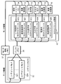
- FIG. 1 is a block diagram showing a configuration of a motor control system including a motor control device 10 according to an embodiment of the present invention.
- the motor control system detects a motor 50, a load 51 connected to the motor 50, a motor control device 10 for controlling and energizing the motor 50, and a position of a movable part in the motor 50. And an upper controller 60 that controls the motor control device 10 by an operation command notification or the like.
- a motor control system a configuration example of a system mainly for industrial use is given. That is, in this motor control system, a motor 50 such as a servo motor is controlled and driven by a motor control device 10 called a servo amplifier or the like.
- a motor control device 10 called a servo amplifier or the like.
- an example of a motor provided with a rotor that performs a rotating operation as the movable portion of the motor 50 will be described.
- an example of a motor having such a rotor will be described.
- the present invention can also be applied to a linear motor in which the movable portion performs a linear operation.
- Such a motor 50 includes a stator having three-phase windings of U phase, V phase, and W phase, and a rotor that is disposed so as to be rotatable about a rotation axis so as to face the stator.
- a brushless motor is preferred.
- the rotor of the motor 50 rotates when the stator winding is energized and driven by the motor control device 10. Then, the rotor 51 is driven to rotate so that the load 51 rotates through the rotation shaft.
- the motor 50 is equipped with an encoder 59 as a position sensor for detecting the rotational position of the rotor.
- the encoder 59 outputs a position detection signal Pdet indicating the detected rotational position.
- the position detection signal Pdet is supplied from the encoder 59 to the motor control device 10.
- the motor control device 10 is communicatively connected to the host controller 60.
- the host controller 60 is connected to the motor control device 10 in order to set parameters or give operation commands to the motor control device 10.
- a personal computer is used as the host controller 60 for parameter setting or the like, and a programmable logic controller (PLC) or motion controller is used for giving an operation command.
- PLC programmable logic controller
- the host controller 60 sends various types of information including an operation command to the motor control device 10 and receives various types of information from the motor control device 10 so that the motor 50 performs a desired movement operation. For example, when the rotor position of the motor 50 is controlled by the motor control device 10, the host controller 60 notifies the target position command, and when the rotor speed is controlled, the host controller 60 notifies the target speed command.
- this motor control system is an industrial system.
- the host controller 60 is equipped not only with a command to the motor control device 10 but also with various software such as an application program related to motor control, and executes various processes by connection with the motor control device 10.
- the host controller 60 is used for programming of user modules relating to the customization function in the present embodiment, setting of various parameters for setting characteristics and functions in the motor control device 10, and other auto-tuning and control. Equipped with software for status monitoring, data measurement, error notification, etc.
- the motor control device 10 connected to the host controller 60 has a feedback control function that operates so as to follow the operation command while detecting and estimating the movement position and speed of the motor. That is, as a basic function, the motor control device 10 moves the rotor of the motor 50 so as to follow the operation command supplied from the host controller 60 by feedback control using the position detection signal Pdet from the encoder 59. Is controlling.
- the motor control device 10 includes a one-chip microcomputer (hereinafter referred to as a microcomputer) 20 having a CPU (Central Processing Unit) 21, a communication connection unit 11, a drive circuit unit 12, A panel operation unit 13, an input / output terminal unit 14, a power supply circuit unit 15, and a protection circuit unit 16 are provided.
- a microcomputer having a CPU (Central Processing Unit) 21, a communication connection unit 11, a drive circuit unit 12, A panel operation unit 13, an input / output terminal unit 14, a power supply circuit unit 15, and a protection circuit unit 16 are provided.
- a microcomputer 20 having a CPU (Central Processing Unit) 21, a communication connection unit 11, a drive circuit unit 12, A panel operation unit 13, an input / output terminal unit 14, a power supply circuit unit 15, and a protection circuit unit 16 are provided.
- CPU Central Processing Unit
- the communication connection unit 11 is provided for data communication with the host controller 60, and transmits and receives data to and from the host controller 60. Specifically, it is a data transmission / reception circuit corresponding to a serial communication standard such as RS232C / 485 or a USB (Universal Serial Bus) standard.
- a serial communication standard such as RS232C / 485 or a USB (Universal Serial Bus) standard.
- RTEX Realtime Express
- EtherCAT communication which is a dedicated FA network communication specification, is often used.
- the panel operation unit 13 is provided for an interface with a user who uses the motor control device 10. With this panel operation unit 13, the user directly inputs parameters and data to the motor control device 10, and presents data in the motor control device 10 directly to the user.
- the user input function includes, for example, a combination of button switches, a dip switch, and a rotary switch.
- a presentation function with respect to a user it is a 7 segment display, for example.
- the user operates the motor control device 10 via the panel operation unit 13. In practice, the operation of the motor control device 10 is performed using the panel operation unit 13 for simple operations and the host controller 60 for advanced operations.
- the input / output terminal unit 14 is provided for data connection with an external device by digital I / O or analog / pulse signals.
- the input / output terminal unit 14 is a terminal such as a connector for inputting data to the motor control device 10 and outputting data from the motor control device 10.
- the protection circuit unit 16 is a series of protection circuits provided to ensure safety in the motor control device 10 and the motor control system, such as protection related to power supply, protection against overheating, and protection against overload.
- the power supply circuit unit 15 is a power source for supplying necessary power to each unit in the motor control device 10.
- the microcomputer 20 basically performs a motor control process which is the main function of the motor control device 10.
- the microcomputer 20 incorporates a motor control program for performing motor control processing, and the built-in CPU 21 executes processing according to the program to control the rotation operation of the motor.
- the microcomputer 20 is supplied with an operation command from the host controller 60 via the communication connection unit 11, and is supplied with the position detection signal Pdet from the encoder 59.
- the microcomputer 20 generates a motor control signal Dd such that the motor movement based on the position detection signal Pdet follows the operation command, and outputs the motor control signal Dd to the drive circuit unit 12. More specifically, the microcomputer 20 executes not only such motor control processing but also processing according to another processing program, and details thereof will be further described below.
- the motor control signal Dd generated by the microcomputer 20 is supplied to the drive circuit unit 12.
- the drive circuit unit 12 includes a so-called inverter, and generates a motor drive signal Vd corresponding to the supplied motor control signal Dd using the inverter. By applying this motor drive signal Vd to the winding of the motor 50, the motor 50 is energized and the rotor in the motor rotates.
- the microcomputer 20 includes a CPU 21, a communication interface unit 24, a panel interface unit 25, an external interface unit 26, a RAM 30, a ROM 40, a user module memory 32, a control parameter memory 34, A buffer memory 36, a monitor information memory 37, and an internal bus 29 for connecting digital signals such as data and addresses of these units within the microcomputer 20 are provided.
- a communication interface unit (hereinafter, appropriately referred to as a communication I / F unit) 24 transmits / receives data to / from the communication connection unit 11. That is, the communication I / F unit 24 transmits the data received by the communication connection unit 11 to the CPU 21 via the internal bus 29 and receives the data generated by the CPU 21 via the internal bus 29. 11 is transmitted.
- Panel interface unit (hereinafter referred to as panel I / F unit as appropriate) 25 performs data transmission / reception with panel operation unit 13 and input / output terminal unit 14. That is, the panel I / F unit 25 transmits the data input to the panel operation unit 13 to the CPU 21 via the internal bus 29 and receives the data generated by the CPU 21 via the internal bus 29 for panel operation. The data is transmitted to the unit 13. Similarly, the panel I / F unit 25 transmits data input to the input terminal of the input / output terminal unit 14 to the CPU 21 via the internal bus 29, and transmits data generated by the CPU 21 via the internal bus 29. Are received and transmitted to the output terminal of the input / output terminal section 14.
- External interface unit (hereinafter referred to as an external I / F unit as appropriate) 26 inputs and outputs various signals such as control signals between microcomputer 20 and each circuit in motor control device 10.
- the external I / F unit 26 outputs to the drive circuit unit 12 a PWM (Pulse Width Modulation) signal, which is a signal that is pulse-width modulated in accordance with the drive amount, as the motor control signal Dd.
- a digital signal corresponding to the drive amount is supplied from the CPU 21 to the external I / F unit 26 via the internal bus 29.
- the external I / F unit 26 converts the digital signal into a PWM signal and outputs the PWM signal.
- the external I / F unit 26 takes in the position detection signal Pdet from the encoder 59. In this case, the external I / F unit 26 converts the supplied position detection signal Pdet into a digital signal indicating the position. The external I / F unit 26 transfers the digital signal to the CPU 21 via the internal bus 29. Further, the external I / F unit 26 is also connected to the protection circuit unit 16 and the power supply circuit unit 15 and inputs and outputs control signals, detection / measurement signals, and the like.
- a ROM (Read Only Memory) 40 is a nonvolatile read-only memory, and mainly stores an embedded program for causing the CPU 21 to execute various processes and controls inside the apparatus.
- the ROM 40 functions as a program storage unit that stores such a program.
- the ROM 40 stores main programs such as a management program for managing various processes and controls and a motor control program for performing motor control processes.
- a management program area 41 stores a management program
- a customization module area 42 stores a customization module group described in detail below
- a motor control module area 46 stores a motor control module.
- the motor control program is stored in the motor control program area 43 and the default value of the control parameter referred to by the motor control program is stored in the parameter default value area 44.
- the ROM 40 is not limited to a non-writable ROM, but can be rewritten, such as a rewritable flash memory, and data can be written to an EEPROM or even an external storage medium can be used. May be. In short, as a function of the ROM 40 here, it is sufficient that the user cannot easily access or rewrite the stored program due to the nature of the program to be stored.
- the CPU 21 is a microprocessor, and sequentially reads a program stored in the ROM 40 or the like via the internal bus 29 and operates according to the read program, thereby executing processing corresponding to the program.
- a RAM (Random Access Memory) 30 is a rewritable and randomly accessible memory, and is used for work performed by the CPU 21.
- a user module memory 32, a control parameter memory 34, a buffer memory 36, and a monitor information memory 37 are further provided.
- These memories are also rewritable and randomly accessible memories like the RAM 30.
- these memories are divided into functions as described above. For example, a user module memory area, a control parameter memory area, a buffer memory area, and a monitor information memory area are used. Furthermore, a configuration in which a specific area in the RAM 30 is further provided may be used.
- the control parameter memory 34 is a memory that stores control parameters referred to by the motor control program.
- the CPU 21 executes processing based on the control parameters stored in the parameter default value area 44 only at startup. Thereafter, the CPU 21 executes processing based on the control parameters stored in the control parameter memory 34.
- the motor control device 10 is configured so that the control parameters stored in the control parameter memory 34 can be appropriately changed as the processing proceeds.
- the motor control program is basically a program for controlling the operation of the motor based on the feedback control process.
- the control parameter here is a variable that is set in order to specify the characteristic and function in the control including the feedback control for the motor.
- the control parameters here are, for example, settings of various gains and filters in the feedback control loop. Examples of the gain include a proportional gain, an integral gain, a differential gain, and a feed forward gain with respect to control of position, speed, torque, and the like. Filter settings include frequency, bandwidth, attenuation, and the like.
- control parameters include switching of characteristics associated with control and processing, designation of switching of position, speed, and torque control.
- the CPU 21 executes motor control processing based on such control parameters stored in the control parameter memory 34. For example, the CPU 21 executes processing based on the initial value “g0” of the control gain G stored in the control parameter memory 34. After that, when the value of the control gain in the control parameter memory 34 is changed to “g1”, the CPU 21 executes processing based on the control gain G of the changed value “g1”.
- the monitor information memory 37 is a memory that collectively stores the setting state in each part in the motor control device 10 as data.
- the CPU 21 can set the communication connection unit 11, the drive circuit unit 12, the panel operation unit 13, the input / output terminal unit 14, the power supply circuit unit 15, the protection circuit unit 16, and the like.
- the information being measured is monitored.
- These pieces of information are recorded in the monitor information memory 37 as monitor information. Examples of such monitor information include, for example, data and transmission / reception data related to the communication method and communication rate being used in the communication connection unit 11, input and output display setting values in the panel operation unit 13, and the input / output terminal unit 14 For example, the value of the terminal.
- the user module memory 32 is a memory for storing a user program created by the user as one module and storing the user program in units of modules, and functions as a user module storage unit. That is, the motor control system according to the present embodiment is configured such that the user can create a desired specific function as such a user module. Then, the user module is stored in the user module memory 32. Specifically, the user module is a program for allowing the user to execute such a specific function. That is, when the CPU 21 reads and executes the program of this module, processing of the function that the user wants to operate is executed.
- a function specified to change a certain control gain G can be a user module in the present embodiment.
- the user can create a user module that changes the control gain G, save it in the user module memory 32, and operate it.
- the user module that executes the process related to the specific function is configured to be formed by the user.
- the buffer memory 36 is a readable / writable memory that can be used by being read or written by the user module stored in the user module memory 32.
- Each module is a program.
- the CPU 21 executes processing such as reading and writing memory according to the module program.
- the description will be made using expressions that allow the module to execute processing, such as the module reading and writing the memory as appropriate.
- the microcomputer 20 is configured.
- the customization module area 42 of the ROM 40 stores a customization module group, that is, a plurality of customization modules.
- the customization module area 42 functions as a customization module storage unit.
- the customization module is configured by a batch program corresponding to a specific function.
- the user module can be changed by the user, while the customization module is a set of programs previously incorporated in the ROM 40 which cannot be written, and is configured so that the user cannot freely change it.
- the customization module is configured by a program including a reference to the buffer memory 36. A plurality of such customization modules are collected for each functional unit to constitute a customization module group. In the present embodiment, such a customization module is used so that customization is possible by changing the setting of a specific function in each part in the motor control device 10.
- Examples of functions of such a customization module include, for example, changing control parameters, changing input and output display settings on the panel operation unit 13, and outputting data in the buffer memory 36 on the panel operation unit 13. There are functions such as displaying and sending to the communication connection unit 11.
- the customization module for example, there is a series of gain settings such as a speed proportional gain, a speed integral gain, and a speed feedforward gain in a control parameter.
- the customization module refers to the value set in the buffer memory 36 and sets the corresponding gain value in the control parameter memory 34.
- a customization module that executes a change process of a specific function in a customization element is formed, and a customization module group is configured by a set of customization modules.
- a customized module group for executing a specific function changing process is formed in advance, and a user module can be formed by a user. And in this Embodiment, it is set as the structure which a user can change with respect to a specific function, or can add a specific function using a user module and a customization module group. In other words, this embodiment makes it possible to provide a customization element for a user for each functional unit by using a user module and a customization module group.
- the buffer module 36 is provided so that the user module writes data and the customization module reads the data. That is, the present embodiment is configured such that the user can change the function as the customization element only through the buffer memory 36.
- a customization module group is configured and a user can form a user module.
- a buffer memory 36 accessible from each of the customization module and the user module is provided.
- the customization module is configured to execute processing relating to the specific function based on data received from the user module via the buffer memory 36. More specifically, the processing of the user module is restricted so that the user module can write only to the buffer memory 36, and the customization module is customized so that the processing is executed using the data in the buffer memory 36 as a parameter. Module processing is restricted.
- the user can easily and quickly change the specific function without risk of malfunction or deterioration in safety. It is possible.
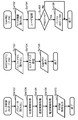
- FIG. 2 is a block diagram showing a configuration of a main part related to the customization function of the motor control device 10 in the present embodiment.
- the customization module group stored in the customization module area 42 of the ROM 40, the user module written in the user module memory 32, and the customization module and the user module can be accessed.
- a customized function is realized by the buffer memory 36. It should be noted that although the CPU 21 executes the process correctly, it will be described here that each module also executes the process, as in the above-described annotation.
- FIG. 2 shows an example in which the following customization module is stored in the ROM 40.
- the area 420 is a motor control customization module
- the area 421 is a communication connection customization module
- the area 423 is a panel operation customization module
- the area 424 is an input / output customization module
- the area 425 is Is a power supply customization module
- at least one protection circuit customization module is stored in each area 426.
- the motor control customization module is a module that mainly changes the set value of the control parameter memory 34, and a set of such modules is stored in the area 420.
- Each of the modules here corresponds to a specific function or characteristic in motor control.
- parameters in processing according to the motor control program are changed.
- the first module corresponding to the speed control is classified as a speed proportional gain
- the second module is a speed integral gain
- the third module is a speed feed forward gain. Change the set value.
- the communication connection customization module is a module that performs operations related to the data transmission / reception function in the communication connection unit 11, and a set of such modules is stored in the area 421. By executing the module here, for example, an operation related to data transmission / reception by the communication connection unit 11 is changed. As a specific example, the communication method and communication speed (communication baud rate) with the host controller 60 are changed.
- the panel operation customization module is a module for performing operations related to the panel operation function in the panel operation unit 13, and a set of such modules is stored in the area 423. By executing the module here, for example, an operation related to user input or user presentation of the panel operation unit 13 is performed. As a specific example, the data stored at the address in the buffer memory 36 specified by the parameter is displayed by the display function of the panel, or the user input data is stored at the address of the buffer memory 36 specified by the parameter. To do.
- the input / output customization module is a module that performs operations related to input / output data at the input / output terminal unit 14, and a set of such modules is stored in the area 424. By executing the module here, for example, an operation related to input / output data of the input / output terminal unit 14 is performed. As a specific example, data stored at the address in the buffer memory 36 specified by the parameter is output from the data output terminal, or data at the data input terminal is stored at the address of the buffer memory 36 specified by the parameter. To do.
- the power supply customization module is a module that performs operations related to the power supply in the power supply circuit unit 15, and a set of such modules is stored in the area 425. By executing the module here, for example, an operation related to power supply from the power supply circuit unit 15 is changed.
- the protection circuit customization module is a module that performs operations related to protection in the protection circuit unit 16, and a set of such modules is stored in the area 426. By executing the module here, for example, the operation related to the protection function in the protection circuit unit 16 is changed.
- a customization module for executing a change process of a specific function in a customization element is formed, and a customization module group is configured by a set of customization modules.
- the customization module further includes processing for performing various operations as described above in addition to processing for changing a specific function.
- expansion through software update is possible. That is, according to the present embodiment, for example, it is possible to take an approach of gradually enhancing the customization function in the form of an add-on while watching the market trend.
- monitor information memory 37 In addition, in response to the customization module performing processing on the specific functions of each unit, information regarding the specific functions of each unit is captured in the monitor information memory 37. That is, in addition to the setting values set in the control parameter memory 34, the setting values in the communication connection unit 11, the drive circuit unit 12, the panel operation unit 13, the input / output terminal unit 14, the power supply circuit unit 15, and the protection circuit unit 16 Data indicating various information such as data indicating the setting state and measurement data is captured and stored in the monitor information memory 37 as monitor information. As specific examples of monitor information, in addition to the setting values of each control parameter, for example, the communication method in the communication connection unit 11, the input value by the input switch in the panel operation unit 13, the value being displayed on the 7-segment display, etc. It is.
- the customization module, the corresponding function, and the monitor information do not always have to be 1: 1.
- FIG. 2 shows a state in which the user module formed by the user is stored in the user module memory 32 in this way. That is, in FIG. 2, the first user module (user module No. 1) is stored in the area 321 of the user module memory 32, and the Nth user module (user module No. N) is stored in the area 32N. An example is shown.
- User module is a module composed of a batch program created by the user.
- a command as a series of programming elements is provided.
- types in the series of commands in addition to arithmetic operations such as addition / subtraction / multiplication / division, logical operations such as logical sum, logical product and shift, comparison and branch instructions, and instructions for reading the contents of each memory, An instruction to write to the address specified by the parameter is prepared.
- the user can program these commands in combination.
- the user module can use the monitor information memory 37 to obtain the setting state in each unit in the motor control device 10.
- the write instruction to the memory in the user module is limited to the write to the buffer memory 36 as shown in FIG. That is, the user module can write only to the buffer memory 36.
- the customization module executes processing using at least the data in the buffer memory 36 as a parameter, as shown in FIG.
- the processing of the customization module is also limited so that the customization module executes the process using only the data in the buffer memory 36 as a parameter.
- the customization function operates as follows based on the customization method of the present embodiment.
- a series of commands created by the user is stored in the user module memory 32, a program by the user is formed, and a user module configured by this program is formed.
- the user module stored in the user module memory 32 executes processing related to the specific function according to the procedure of those commands.
- the user module writes the processing result as data in the buffer memory 36.
- a customization module related to the specific function is activated.
- the activated customization module refers to the buffer memory 36 according to a procedure incorporated in advance.
- the customization module executes, for example, a change process using the referenced data.
- the customization module is limited to receive data from the user module only through the buffer memory 36.
- the customization function can be implemented, and by providing such a restriction, the risk of malfunction in motor operation and the reduction in safety are suppressed.
- the buffer memory 36 is an interface for clearly separating the functions of the user module and the customization module while connecting the functions of the user module and the customization module.
- this customization method is a method of writing the result of the process in the user module only to the buffer memory 36, the user can check the process result by referring to the buffer memory 36. Therefore, debugging of the user module is facilitated, and there is an effect of preventing malfunction due to this.
- FIG. 3 is a diagram illustrating an example of such an operation of the customization function in the motor control device 10 based on the customization method of the present embodiment.
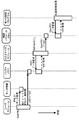
- FIG. 4 is a flowchart showing a motor control program, which is the main process of the motor control device 10, and a process flow between the customization module and the user module for realizing the customization function.
- FIG. 3 and FIG. 4 a detailed operation for implementing the customization function will be described with an example of an operation of changing the position gain P01 in the position control by the motor control.
- an area 420 of the customization module area 42 of the ROM 40 stores a set of modules that mainly change setting values in the control parameter memory 34.
- the modules here for example, “SetGain01 ()” and “SetGain0n ()” for setting the gain, and “SetOffset01 ()” for setting the offset have respective functions.
- the customization module SetGain01 () includes a command based on a notation such as “SET GainP01, BUF # 001” in the program. This command designates the address # 001 in the buffer memory 36 as the notation “BUF # 001”, and designates the address P01 for storing the position gain P01 in the control parameter memory 34 as the notation “GainP01”. Then, the customization module SetGain01 () is activated and this command is executed, whereby the data at the address # 001 in the buffer memory 36 is stored at the address P01 in the control parameter memory 34. That is, the process of each step as shown by SetGain01 () in FIG.
- step Sc102 the buffer memory 36 is read (step Sc102).
- step Sc104 a specific customization process at SetGain01 () is executed (step Sc104).
- step Sc106 the data obtained as a result of the customization process is stored at the address P01 of the control parameter memory 34 (step Sc106), and the process of the customization module SetGain01 () is completed.
- the specific function is a function specified to set the position gain P01.
- the customization module SetGain01 () is used as a customization element customized so that the position gain P01 can be changed in combination with the user module. That is, in this example, in order to change the position gain P01 as one of the customization functions, a customization module SetGain01 () that executes a change process of the position gain P01 is formed.
- the customization module SetGain0n () when the customization module SetGain0n () is activated, the data of the address # 001 in the buffer memory 36 is stored in the address P0n in the control parameter memory 34.
- the customization module SetOffset01 () when the customization module SetOffset01 () is activated, the data at the address # 002 in the buffer memory 36 is stored at the address V01 in the control parameter memory 34.
- the customization module in this embodiment is configured as described above.
- the monitor information memory 37 stores information of each part.
- the value “pnl1” of the panel input data of the panel operation unit 13 is controlled to the address PNL01 of the monitor information memory 37
- the value “p1” of the address P01 of the control parameter memory 34 is controlled to the address P001 of the monitor information memory 37.
- An example is shown in which the value “pn” of the address P0n of the parameter memory 34 is fetched and stored in the address P00n of the monitor information memory 37.
- FIG. 3 shows an example in which, in the user module memory 32, the user module UserN () that is the first user module or the Nth user module is stored as the user module created by the user.
- the command “READ PNL01” indicates an instruction to read data at the address PNL01 in the monitor information memory 37.
- the notation “AND aaa,“ bbb ”” indicates execution of the logical AND of the variable aaa and the value “bbb”.
- the notation “ADD aaa, ccc” indicates execution of addition ADD of variable aaa and variable ccc.
- the notation “WRITE BUF # 001, aaa” indicates an instruction for writing the value of the variable “aaa” to the buffer memory 36 at the address # 001 designated by the parameter “BUF # 001”.
- an instruction for writing to the address specified by the parameter in the buffer memory 36 is prepared. ing.
- the data at the address PNL01 in the monitor information memory 37 is used as the desired data, and the desired processing is executed, so that the write data is created and stored in the variable aaa.
- the buffer memory is executed by the last command based on the notation “WRITE BUF # 001, aaa”.
- the value of variable aaa is stored at address # 001 of 36.
- FIG. 3 shows an example in which the value “100” of the variable aaa is stored in the address # 001 of the buffer memory 36 by the user module UserN ().
- FIG. 4 shows the process of the user module UserN () as the flow of UserN () in the following steps.
- monitor information is read from the monitor information memory 37 (step Su102).
- user processing created by the user such as performing arithmetic processing using the read monitor information, is executed (step Su104).
- it is determined whether or not the value of the variable PNL01 is “0” step Su106). If it is “0”, the value “100” is written in the address # 001 of the buffer memory 36 (step Su108), and the user The process of the module UserN () is finished.
- the user module UserN () has been described in detail for each step. For example, as the user module UserN (), when the value “pnl1” of the panel input data of the panel operation unit 13 becomes the value “0” as an event.
- the module can write the value of the variable aaa at the address # 001 of the buffer memory 36.
- FIG. 4 also shows an example in which the following steps are executed in the motor control program that is the main process of the motor control device 10.
- a set value set in the control parameter memory 34 is read (step Sm102).
- position control processing step Sm104
- speed control processing step Sm106
- current control processing step Sm108
- the customization function operates as follows based on the customization method of the present embodiment.
- a series of commands created by the user is stored in the user module memory 32, a program by the user is formed, and a user module UserN () configured by this program is formed.
- the user module UserN () executes processing related to the specific function according to the procedure of those commands.
- the user module UserN () writes the value “100” of the variable aaa, which is the processing result, as data at address # 001 of the buffer memory 36.
- the customization module SetGain01 () related to the specific function is activated.
- the activated customization module SetGain01 () refers to the address # 001 of the buffer memory 36 in accordance with a procedure incorporated in advance. Then, the customization module SetGain01 () stores the value “100” of the referenced data at the address P01 in the control parameter memory 34. As a result, at the address P01 in the control parameter memory 34, the value “p1” is changed to the value “100”.
- FIG. 5 is a sequence diagram showing a flow of executing each process along the time axis when each process shown in FIG. 4 is started as a task.
- the motor control program as a main task is started at a cycle of 0.25 ms (milliseconds), and the customization module SetGain01 () and the user module UserN () are each sub-tasks every 1 ms (milliseconds).
- An example of starting up is shown.
- the customization module and the user module are activated periodically and independently as shown in the examples of FIGS.
- the function can be executed.
- FIGS. 4 and 5 show an example in which the set value of the position gain P01 is changed with the event that the value of the variable PNL01 becomes “0”.
- the user module UserN () that is subsequently activated as a subtask sends the change value “100” as the processing result to a predetermined address # in the buffer memory 36. Write to 001 as data.
- the customization module SetGain01 () activated as a subtask at the next timing acquires the change value “100” with reference to the buffer memory 36, and the change The value “100” is stored at a predetermined address P01 in the control parameter memory 34.
- the position gain is changed to the change value “100” in the position control process in the motor control process being executed as the main task.
- the user module writes the classification number and setting value of the specific function to be changed to the buffer memory 36
- the customization module specifies the classification number and setting value written in the buffer memory 36. It may be configured to execute the function change process. 4 and FIG. 5, the example in which the two subtasks are both set to 1 ms has been described. However, these may have different activation cycles, and may be either synchronous or asynchronous. Further, it may be activated by an irregular event, and execution only once at initialization is also conceivable.
- the motor control apparatus and the customization method thereof according to the present invention are provided with buffer memories that can be accessed from the customization module and the user module. Then, the user module restricts the processing of the user module so that only the buffer memory can be written, and the customization module executes the processing of the customization module so that the processing is executed using only the data of the buffer memory as a parameter. Is limiting.
- the change process is indirectly performed via the buffer memory, the user can easily and quickly customize the customization unit without any risk of malfunction in the motor operation or a decrease in safety. You can change the specific function of.
- the motor control device and the customization method thereof according to the present invention can be used for industrial machinery such as servo amplifiers and industrial robots because the customization function can be used without risk of malfunction in motor operation or reduction in safety. Useful for motor control devices.
Landscapes
- Engineering & Computer Science (AREA)
- Power Engineering (AREA)
- Physics & Mathematics (AREA)
- General Physics & Mathematics (AREA)
- Automation & Control Theory (AREA)
- Control Of Electric Motors In General (AREA)
Priority Applications (5)
| Application Number | Priority Date | Filing Date | Title |
|---|---|---|---|
| US15/545,716 US10353366B2 (en) | 2015-12-22 | 2016-12-15 | Customization method of motor control device and motor control device |
| KR1020177023781A KR101823847B1 (ko) | 2015-12-22 | 2016-12-15 | 모터 제어 장치의 커스터마이즈 방법, 및 모터 제어 장치 |
| EP16877966.8A EP3236580B1 (en) | 2015-12-22 | 2016-12-15 | Method for customizing motor control device, and motor control device |
| CN201680012954.1A CN107438944B (zh) | 2015-12-22 | 2016-12-15 | 电动机控制装置的定制方法和电动机控制装置 |
| JP2017521182A JP6205588B1 (ja) | 2015-12-22 | 2016-12-15 | モータ制御装置のカスタマイズ方法、およびモータ制御装置 |
Applications Claiming Priority (2)
| Application Number | Priority Date | Filing Date | Title |
|---|---|---|---|
| JP2015250135 | 2015-12-22 | ||
| JP2015-250135 | 2015-12-22 |
Publications (1)
| Publication Number | Publication Date |
|---|---|
| WO2017110061A1 true WO2017110061A1 (ja) | 2017-06-29 |
Family
ID=59089905
Family Applications (1)
| Application Number | Title | Priority Date | Filing Date |
|---|---|---|---|
| PCT/JP2016/005134 WO2017110061A1 (ja) | 2015-12-22 | 2016-12-15 | モータ制御装置のカスタマイズ方法、およびモータ制御装置 |
Country Status (6)
| Country | Link |
|---|---|
| US (1) | US10353366B2 (ko) |
| EP (1) | EP3236580B1 (ko) |
| JP (1) | JP6205588B1 (ko) |
| KR (1) | KR101823847B1 (ko) |
| CN (1) | CN107438944B (ko) |
| WO (1) | WO2017110061A1 (ko) |
Cited By (1)
| Publication number | Priority date | Publication date | Assignee | Title |
|---|---|---|---|---|
| JP7461795B2 (ja) | 2020-05-20 | 2024-04-04 | ミネベアミツミ株式会社 | モータ制御回路、モータ駆動制御装置、及びモータ制御回路の制御方法 |
Families Citing this family (17)
| Publication number | Priority date | Publication date | Assignee | Title |
|---|---|---|---|---|
| DE102017215449A1 (de) * | 2017-09-04 | 2019-03-07 | Lenze Automation Gmbh | Verfahren zum Betreiben eines Anwendungsprogramms zum Ausführen auf einem elektrischen Steuergerät für ein Antriebssystem, elektrisches Steuergerät, Antriebssystem und System |
| WO2019113726A1 (zh) * | 2017-12-11 | 2019-06-20 | 深圳配天智能技术研究院有限公司 | 运动控制器及运动控制的方法 |
| JP6828700B2 (ja) * | 2018-01-19 | 2021-02-10 | 株式会社安川電機 | 電力変換システム、プログラミング支援装置、プログラミング支援方法、プログラム、及び記憶媒体 |
| JP2019153201A (ja) * | 2018-03-06 | 2019-09-12 | 株式会社東芝 | モータ制御システム |
| US11623529B2 (en) | 2018-03-19 | 2023-04-11 | Tula eTechnology, Inc. | Pulse modulated control with field weakening for improved motor efficiency |
| US10944352B2 (en) | 2018-03-19 | 2021-03-09 | Tula eTechnology, Inc. | Boosted converter for pulsed electric machine control |
| US20190288629A1 (en) | 2018-03-19 | 2019-09-19 | Tula eTechnology, Inc. | Pulsed electric machine control |
| CN109050693B (zh) * | 2018-07-11 | 2024-02-02 | 济南大学 | 一种具有跟随功能的上台阶装置及其实现方法 |
| US11628730B2 (en) | 2021-01-26 | 2023-04-18 | Tula eTechnology, Inc. | Pulsed electric machine control |
| EP4308405A1 (en) | 2021-03-15 | 2024-01-24 | TULA eTechnology, Inc. | Methods of optimizing waveforms for electric motors |
| EP4356511A1 (en) | 2021-06-14 | 2024-04-24 | TULA eTechnology, Inc. | Electric machines with efficient torque transitions |
| CN117501614A (zh) | 2021-06-28 | 2024-02-02 | 图拉E技术公司 | 电机的选择性相控制 |
| US11557996B1 (en) | 2021-07-08 | 2023-01-17 | Tula eTechnology, Inc. | Methods of reducing vibrations for electric motors |
| US11345241B1 (en) | 2021-08-12 | 2022-05-31 | Tula eTechnology, Inc. | Method of optimizing system efficiency for battery powered electric motors |
| WO2023038760A1 (en) | 2021-09-08 | 2023-03-16 | Tula eTechnology, Inc. | Electric machine torque adjustment based on waveform integer multiples |
| US11637466B1 (en) | 2021-10-18 | 2023-04-25 | Tula Etechnology Inc. | Mechanical and electromechanical arrangements for field-weakening of an electric machine that utilizes permanent magnets |
| US11888424B1 (en) | 2022-07-18 | 2024-01-30 | Tula eTechnology, Inc. | Methods for improving rate of rise of torque in electric machines with stator current biasing |
Citations (3)
| Publication number | Priority date | Publication date | Assignee | Title |
|---|---|---|---|---|
| JP2005234639A (ja) | 2004-02-17 | 2005-09-02 | Yaskawa Electric Corp | 数値制御装置のカスタマイズ方法および数値制御装置 |
| JP2012244856A (ja) * | 2011-05-23 | 2012-12-10 | Ricoh Co Ltd | モータ制御装置及び画像形成装置 |
| WO2015045549A1 (ja) * | 2013-09-27 | 2015-04-02 | 富士電機株式会社 | 駆動装置 |
Family Cites Families (26)
| Publication number | Priority date | Publication date | Assignee | Title |
|---|---|---|---|---|
| JPS5594502A (en) * | 1979-01-12 | 1980-07-18 | Hitachi Ltd | Electromobile control device |
| JPS6037032B2 (ja) | 1979-09-28 | 1985-08-23 | 株式会社日立製作所 | エレベ−タの案内装置 |
| JPH0710672B2 (ja) * | 1985-07-03 | 1995-02-08 | 株式会社日立製作所 | 電動式パワ−ステアリング制御装置 |
| US5684374A (en) | 1995-07-27 | 1997-11-04 | Allen-Bradley Company, Inc. | Method and apparatus for tuning a motion control system having an external velocity loop |
| JP3457820B2 (ja) * | 1996-12-18 | 2003-10-20 | シャープ株式会社 | 電気洗濯機 |
| JP3332810B2 (ja) * | 1997-07-15 | 2002-10-07 | 株式会社日立製作所 | インバータ制御装置 |
| DE19882631T1 (de) * | 1998-07-16 | 2000-08-10 | Mitsubishi Electric Corp | Wechselrichtervorrichtung |
| ES2155413B1 (es) * | 1999-10-22 | 2002-02-01 | Castellon Melchor Daumal | Mejoras en los sistemas antipinzamiento destinados al automovil. |
| JP4232621B2 (ja) * | 2003-12-08 | 2009-03-04 | 株式会社デンソー | 半導体集積回路装置 |
| JP4097217B2 (ja) * | 2004-04-06 | 2008-06-11 | 本田技研工業株式会社 | 車両用カスタマイズシステム |
| DE102005028663A1 (de) * | 2005-06-15 | 2006-12-21 | Volkswagen Ag | Verfahren und Vorrichtung zum sicheren Kommunizieren einer Komponente eines Fahrzeugs über eine drahtlose Kommunikationsverbindung mit einem externen Kommunikationspartner |
| JP4859029B2 (ja) * | 2006-03-22 | 2012-01-18 | 本田技研工業株式会社 | モータ保護装置 |
| JP4857897B2 (ja) * | 2006-05-12 | 2012-01-18 | 日産自動車株式会社 | 騒音制御方法および騒音制御装置 |
| US20080138169A1 (en) * | 2006-12-08 | 2008-06-12 | Nicholas Jackson | Fastener |
| JP2008176609A (ja) * | 2007-01-19 | 2008-07-31 | Yaskawa Electric Corp | インバータ |
| JP4512145B2 (ja) * | 2008-03-21 | 2010-07-28 | ファナック株式会社 | モータ制御装置 |
| CN101888493B (zh) * | 2009-05-13 | 2013-06-26 | 沈阳同方多媒体科技有限公司 | 一种电视机及对其进行功能定制的方法 |
| US8670859B2 (en) * | 2009-07-09 | 2014-03-11 | Siemens Industry, Inc. | Methods and apparatus for an improved motor control center |
| EP2282297A1 (fr) * | 2009-07-21 | 2011-02-09 | Openways Sas | Système sécurisé de commande d'ouverture de dispositifs de serrure par accréditions acoustiques chiffrées |
| JP2011041343A (ja) * | 2009-08-06 | 2011-02-24 | Toshiba Corp | モータ駆動装置及びモータ駆動方法 |
| US8614622B2 (en) * | 2010-03-08 | 2013-12-24 | Ford Global Technologies, Llc | Method and system for enabling an authorized vehicle driveaway |
| CN102541782A (zh) * | 2011-12-16 | 2012-07-04 | 中国科学院自动化研究所 | Dram访问控制装置与控制方法 |
| JP6147983B2 (ja) * | 2012-10-10 | 2017-06-14 | 株式会社東海理化電機製作所 | 電子キー登録システム |
| CN102981440B (zh) * | 2012-11-02 | 2014-10-29 | 武汉理工大学 | 基于SaaS的智能设备监控管理系统 |
| CN103279401B (zh) * | 2013-05-31 | 2016-01-27 | 华为技术有限公司 | 一种访问存储器的方法及装置 |
| CN103490700B (zh) * | 2013-10-11 | 2016-07-13 | 河南理工大学 | 空间矢量脉冲宽度调制试验装置及直流母线电压优化方法 |
-
2016
- 2016-12-15 EP EP16877966.8A patent/EP3236580B1/en active Active
- 2016-12-15 KR KR1020177023781A patent/KR101823847B1/ko active IP Right Grant
- 2016-12-15 JP JP2017521182A patent/JP6205588B1/ja active Active
- 2016-12-15 WO PCT/JP2016/005134 patent/WO2017110061A1/ja active Application Filing
- 2016-12-15 US US15/545,716 patent/US10353366B2/en active Active
- 2016-12-15 CN CN201680012954.1A patent/CN107438944B/zh active Active
Patent Citations (3)
| Publication number | Priority date | Publication date | Assignee | Title |
|---|---|---|---|---|
| JP2005234639A (ja) | 2004-02-17 | 2005-09-02 | Yaskawa Electric Corp | 数値制御装置のカスタマイズ方法および数値制御装置 |
| JP2012244856A (ja) * | 2011-05-23 | 2012-12-10 | Ricoh Co Ltd | モータ制御装置及び画像形成装置 |
| WO2015045549A1 (ja) * | 2013-09-27 | 2015-04-02 | 富士電機株式会社 | 駆動装置 |
Non-Patent Citations (1)
| Title |
|---|
| See also references of EP3236580A4 |
Cited By (1)
| Publication number | Priority date | Publication date | Assignee | Title |
|---|---|---|---|---|
| JP7461795B2 (ja) | 2020-05-20 | 2024-04-04 | ミネベアミツミ株式会社 | モータ制御回路、モータ駆動制御装置、及びモータ制御回路の制御方法 |
Also Published As
| Publication number | Publication date |
|---|---|
| CN107438944B (zh) | 2019-01-29 |
| KR101823847B1 (ko) | 2018-01-30 |
| KR20170103017A (ko) | 2017-09-12 |
| EP3236580A4 (en) | 2018-04-25 |
| EP3236580A1 (en) | 2017-10-25 |
| JPWO2017110061A1 (ja) | 2017-12-21 |
| JP6205588B1 (ja) | 2017-10-04 |
| US10353366B2 (en) | 2019-07-16 |
| EP3236580B1 (en) | 2023-03-08 |
| US20180032047A1 (en) | 2018-02-01 |
| CN107438944A (zh) | 2017-12-05 |
Similar Documents
| Publication | Publication Date | Title |
|---|---|---|
| JP6205588B1 (ja) | モータ制御装置のカスタマイズ方法、およびモータ制御装置 | |
| JP5801143B2 (ja) | モータシステムおよびモータ制御装置 | |
| JP5241706B2 (ja) | 電気駆動システムの電子制御装置、電気駆動システムの電子駆動ユニットおよび電気駆動システム | |
| US8374716B1 (en) | System and method for reconfigurable fans | |
| JP5230644B2 (ja) | 電動機の駆動装置および駆動制御装置 | |
| JPH103307A (ja) | 数値制御装置 | |
| JP2007073008A (ja) | 位置決め装置 | |
| US10416663B2 (en) | Motor control apparatus, motor control method, information processing program, and recording medium | |
| WO2015145562A1 (ja) | プログラミング装置及び実行コード生成方法 | |
| JP6323685B2 (ja) | プログラマブルコントローラ | |
| JP6374456B2 (ja) | 電子機器及び数値制御装置 | |
| JP6393905B2 (ja) | モータ駆動装置 | |
| JP6587754B2 (ja) | 空気調和機 | |
| JP6146277B2 (ja) | インバータ制御装置およびその周辺装置 | |
| JP6812727B2 (ja) | 安全制御ユニット、安全制御方法、安全制御プログラム | |
| CN106970652B (zh) | 运动控制器 | |
| US10802458B2 (en) | System for building an industrial control program from device type classes having device specific instructions | |
| JP7461795B2 (ja) | モータ制御回路、モータ駆動制御装置、及びモータ制御回路の制御方法 | |
| JP6612866B2 (ja) | サーボモータ駆動装置 | |
| JP2005339018A (ja) | 数値制御装置 | |
| JP6002021B2 (ja) | スレーブ機器 | |
| JP2005310023A (ja) | 制御パラメータ調整装置 | |
| JPWO2019124008A1 (ja) | 工具並びに工具の制御回路及び制御方法 | |
| JP2019179377A (ja) | プログラマブルコントローラ及びプログラマブルコントローラシステム | |
| JP2001290511A (ja) | 制御システム |
Legal Events
| Date | Code | Title | Description |
|---|---|---|---|
| ENP | Entry into the national phase |
Ref document number: 2017521182 Country of ref document: JP Kind code of ref document: A |
|
| REEP | Request for entry into the european phase |
Ref document number: 2016877966 Country of ref document: EP |
|
| ENP | Entry into the national phase |
Ref document number: 20177023781 Country of ref document: KR Kind code of ref document: A |
|
| 121 | Ep: the epo has been informed by wipo that ep was designated in this application |
Ref document number: 16877966 Country of ref document: EP Kind code of ref document: A1 |
|
| NENP | Non-entry into the national phase |
Ref country code: DE |