WO2017104290A1 - 車両制御装置 - Google Patents
車両制御装置 Download PDFInfo
- Publication number
- WO2017104290A1 WO2017104290A1 PCT/JP2016/082903 JP2016082903W WO2017104290A1 WO 2017104290 A1 WO2017104290 A1 WO 2017104290A1 JP 2016082903 W JP2016082903 W JP 2016082903W WO 2017104290 A1 WO2017104290 A1 WO 2017104290A1
- Authority
- WO
- WIPO (PCT)
- Prior art keywords
- output
- signal
- arithmetic processing
- input
- processing unit
- Prior art date
- Legal status (The legal status is an assumption and is not a legal conclusion. Google has not performed a legal analysis and makes no representation as to the accuracy of the status listed.)
- Ceased
Links
Images

Classifications
-
- F—MECHANICAL ENGINEERING; LIGHTING; HEATING; WEAPONS; BLASTING
- F02—COMBUSTION ENGINES; HOT-GAS OR COMBUSTION-PRODUCT ENGINE PLANTS
- F02D—CONTROLLING COMBUSTION ENGINES
- F02D45/00—Electrical control not provided for in groups F02D41/00 - F02D43/00
-
- F—MECHANICAL ENGINEERING; LIGHTING; HEATING; WEAPONS; BLASTING
- F02—COMBUSTION ENGINES; HOT-GAS OR COMBUSTION-PRODUCT ENGINE PLANTS
- F02D—CONTROLLING COMBUSTION ENGINES
- F02D41/00—Electrical control of supply of combustible mixture or its constituents
- F02D41/009—Electrical control of supply of combustible mixture or its constituents using means for generating position or synchronisation signals
-
- F—MECHANICAL ENGINEERING; LIGHTING; HEATING; WEAPONS; BLASTING
- F02—COMBUSTION ENGINES; HOT-GAS OR COMBUSTION-PRODUCT ENGINE PLANTS
- F02D—CONTROLLING COMBUSTION ENGINES
- F02D41/00—Electrical control of supply of combustible mixture or its constituents
- F02D41/24—Electrical control of supply of combustible mixture or its constituents characterised by the use of digital means
- F02D41/26—Electrical control of supply of combustible mixture or its constituents characterised by the use of digital means using computer, e.g. microprocessor
- F02D41/28—Interface circuits
-
- F—MECHANICAL ENGINEERING; LIGHTING; HEATING; WEAPONS; BLASTING
- F02—COMBUSTION ENGINES; HOT-GAS OR COMBUSTION-PRODUCT ENGINE PLANTS
- F02D—CONTROLLING COMBUSTION ENGINES
- F02D41/00—Electrical control of supply of combustible mixture or its constituents
- F02D41/30—Controlling fuel injection
- F02D41/38—Controlling fuel injection of the high pressure type
- F02D41/40—Controlling fuel injection of the high pressure type with means for controlling injection timing or duration
- F02D41/401—Controlling injection timing
-
- G—PHYSICS
- G01—MEASURING; TESTING
- G01B—MEASURING LENGTH, THICKNESS OR SIMILAR LINEAR DIMENSIONS; MEASURING ANGLES; MEASURING AREAS; MEASURING IRREGULARITIES OF SURFACES OR CONTOURS
- G01B21/00—Measuring arrangements or details thereof, where the measuring technique is not covered by the other groups of this subclass, unspecified or not relevant
- G01B21/22—Measuring arrangements or details thereof, where the measuring technique is not covered by the other groups of this subclass, unspecified or not relevant for measuring angles or tapers; for testing the alignment of axes
-
- F—MECHANICAL ENGINEERING; LIGHTING; HEATING; WEAPONS; BLASTING
- F02—COMBUSTION ENGINES; HOT-GAS OR COMBUSTION-PRODUCT ENGINE PLANTS
- F02D—CONTROLLING COMBUSTION ENGINES
- F02D41/00—Electrical control of supply of combustible mixture or its constituents
- F02D41/24—Electrical control of supply of combustible mixture or its constituents characterised by the use of digital means
- F02D41/26—Electrical control of supply of combustible mixture or its constituents characterised by the use of digital means using computer, e.g. microprocessor
- F02D41/28—Interface circuits
- F02D2041/281—Interface circuits between sensors and control unit
-
- F—MECHANICAL ENGINEERING; LIGHTING; HEATING; WEAPONS; BLASTING
- F02—COMBUSTION ENGINES; HOT-GAS OR COMBUSTION-PRODUCT ENGINE PLANTS
- F02D—CONTROLLING COMBUSTION ENGINES
- F02D2250/00—Engine control related to specific problems or objectives
- F02D2250/12—Timing of calculation, i.e. specific timing aspects when calculation or updating of engine parameter is performed
-
- F—MECHANICAL ENGINEERING; LIGHTING; HEATING; WEAPONS; BLASTING
- F02—COMBUSTION ENGINES; HOT-GAS OR COMBUSTION-PRODUCT ENGINE PLANTS
- F02D—CONTROLLING COMBUSTION ENGINES
- F02D41/00—Electrical control of supply of combustible mixture or its constituents
- F02D41/02—Circuit arrangements for generating control signals
- F02D41/14—Introducing closed-loop corrections
- F02D41/1401—Introducing closed-loop corrections characterised by the control or regulation method
-
- F—MECHANICAL ENGINEERING; LIGHTING; HEATING; WEAPONS; BLASTING
- F02—COMBUSTION ENGINES; HOT-GAS OR COMBUSTION-PRODUCT ENGINE PLANTS
- F02D—CONTROLLING COMBUSTION ENGINES
- F02D41/00—Electrical control of supply of combustible mixture or its constituents
- F02D41/02—Circuit arrangements for generating control signals
- F02D41/14—Introducing closed-loop corrections
- F02D41/1438—Introducing closed-loop corrections using means for determining characteristics of the combustion gases; Sensors therefor
- F02D41/1439—Introducing closed-loop corrections using means for determining characteristics of the combustion gases; Sensors therefor characterised by the position of the sensor
- F02D41/1441—Plural sensors
Definitions
- the present invention relates to a vehicle control device.
- the ECU Electronic Control Unit receives sensor signals for detecting the crank rotation angle and cam angle of the engine, calculates the crank rotation angle and cam angle with an arithmetic processing unit, and based on the calculated results, A technique for controlling the timing of fuel injection and ignition for a cylinder is widely used.
- sensor signals are not limited to one input at a time.
- a signal processing circuit that can be shared by both an MPU (magnetic pickup) type rotation sensor and an MRE (magnetoresistive element) type rotation sensor is known (for example, a patent). Reference 1).
- an object of the present invention is to provide a vehicle control device capable of outputting a signal from a sensor input to an arithmetic processing device to the outside with a reduced delay.
- the present invention includes an arithmetic processing device having a pair of input ports and output ports assigned to a sensor signal indicating a signal output from one sensor, and the arithmetic processing device includes the input Calculation processing is performed using the sensor signal input from the port, and the sensor signal is output from the output port.
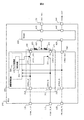
- ECU which allocated the signal with respect to the same sensor to the input port and output port of the arithmetic processing unit of the 1st Embodiment of this invention. It is a block diagram of ECU comprised so that the cam angle sensor signal selected from the some cam angle sensor signal of the 2nd Embodiment of this invention could be output.
- FIG. 1 is a block diagram in which portions for signal processing of a cam angle sensor and a crank rotation angle sensor in an ECU are extracted.
- the ECU 100 receives an input signal from the cam angle sensor and an input signal from the crank rotation angle sensor from a cam angle sensor input signal A terminal 110 and a crank rotation angle sensor input signal terminal 120, respectively.
- the CAM_A_IN signal input to the cam angle sensor input signal A terminal 110 passes through a pull-up circuit, a low-pass filter using a resistor capacitor, and the like, and is calculated by an arithmetic processing unit 200 (for example, a microcomputer).
- the data is input to the processing device input terminal 1 (210).
- the CRANK_IN signal input to the crank rotation angle sensor input signal terminal 120 is input to the arithmetic processing unit input terminal 3 (220) of the arithmetic processing unit 200.
- the software processing unit 300 in the arithmetic processing unit 200 controls the timing of fuel injection and ignition for each cylinder of the engine based on the cam angle sensor input signal and the crank rotation angle sensor input signal.
- the signals of the cam angle sensor and the crank rotation angle sensor are output in a suitable signal format to another unit or circuit (not shown) connected to the ECU 100.
- the preferred signal format is a low-side driver output format output by the driver IC 400.
- the driver IC 400 When a high level signal is input to the driver IC output control terminal 1 (410), the driver IC 400 turns on the low side switch inside the driver IC, and the output of the driver IC output terminal 1 (435) becomes low level. Be controlled. On the other hand, when a low-level signal is input to the driver IC output control terminal 1 (410), the low-side switch inside the driver IC is turned OFF, and the output of the driver IC output terminal 1 (435) is output from another unit or circuit side. It is controlled to become high level by pull-up.
- the driver IC 400 has a combination of a driver IC output control terminal 2 (420) and a driver IC output terminal 2 (440) having the same function.
- the cam angle sensor signal is output from the arithmetic processing unit output terminal 1 (230) and input to the driver IC output control terminal 1 (410).
- the signal of the crank rotation angle sensor is output from the arithmetic processing unit output terminal 3 (240) and input to the driver IC output control terminal 2 (420).
- the signals of the cam angle sensor and the crank rotation angle sensor are respectively sent to another unit or circuit (not shown) connected to the ECU 100. It is possible to satisfy the demand for output in a suitable signal format from the cam angle output signal terminal (130) and the crank rotation angle output signal terminal (140).
- the driver IC has been described as an example with a built-in low-side switch. However, the driver IC does not depend on the type of switch, and it is applicable regardless of the output stage circuit type such as a single FET or buffer circuit instead of the driver IC. Is possible.
- the arithmetic processing device input terminal 1 (210) and the arithmetic processing device output terminal 1 (230) perform arithmetic operations on the same sensor.
- An ETPU1 signal is assigned as a signal inside the processing device, and the arithmetic processing device 200 performs arithmetic processing in the software processing unit 300 using a signal input from the arithmetic processing device input terminal 1 (210) and inputs the arithmetic processing device.
- a signal input from the terminal 1 (210) is output from the arithmetic processing unit output terminal 1 (230).
- the ECU (100: vehicle control device) is a pair of arithmetic processing device input terminals 1 (210: input ports) and arithmetic processing device output terminals 1 assigned to sensor signals indicating signals output from one sensor.
- An arithmetic processing unit (200) having (230: output port) is provided.
- the arithmetic processing device (200) performs arithmetic processing using the sensor signal input from the arithmetic processing device input terminal 1 (210) and outputs the sensor signal from the arithmetic processing device output terminal 1 (230).
- the signal from the sensor input to the arithmetic processing unit (200) can be output to the outside with a reduced delay. Specifically, it is possible to perform calculation using the input signal from the sensor in the arithmetic processing device (200), while outputting the signal from the arithmetic processing device (200) while suppressing delay.
- the cam angle sensor and crank rotation angle sensor signals are to be output to another unit or circuit (not shown) connected to the ECU 100 without going through the arithmetic processing unit 200
- the signal of the angle sensor input signal A terminal 110 is input to both the arithmetic processing unit input terminal 1 (210) and the driver IC output control terminal 1 (410), and the signal of the crank rotation angle sensor input signal terminal 120 is input to the arithmetic processing unit.
- a method of inputting to both the terminal 3 (220) and the driver IC output control terminal 2 (420) is conceivable.
- FIG. 2 is a block diagram in which portions for performing signal processing of the cam angle sensor and the crank rotation angle sensor in an ECU having two cam angle sensors are extracted.
- a signal from a cam angle sensor A (not shown) is input to the ECU 100 from a cam angle sensor input signal A terminal 110, and a signal from the cam angle sensor B is input to the ECU 100 from a cam angle sensor input signal B terminal 111, respectively. Is done.
- the signal of the cam angle sensor input signal A terminal 110 is sent to the arithmetic processing device input terminal 1 (210), and the signal of the cam angle sensor input signal B terminal 111 is sent to the arithmetic processing device input terminal 2 (211). ).
- the signal from the crank rotation angle sensor is the same as that in the first embodiment, and thus the description thereof is omitted.
- the software processing unit 300 in the arithmetic processing unit performs fuel injection and ignition for each cylinder of the engine based on sensor signals from the cam angle sensor A, the cam angle sensor B, and the crank rotation angle sensor. Control timing.
- either the cam angle sensor A or the cam angle sensor B and the signal of the crank rotation angle sensor are output in a suitable signal format to another unit or circuit (not shown) connected to the ECU 100.
- another unit or circuit not shown
- the signal for the cam angle sensor and the crank rotation angle sensor is suitable for the request to output to another unit or circuit (not shown) connected to the ECU 100.
- the signals of the cam angle sensor and the crank rotation angle sensor have very important timing for engine control.
- the request for the delay time and the timing difference between the signals of the cam angle sensor and the crank rotation angle sensor. A request for is generated.
- the arithmetic processing device input terminal 1 (210) and the arithmetic processing device output terminal 1 (230) are the same.
- the ETPU1 signal is assigned to the sensor as a signal inside the arithmetic processing unit, and the arithmetic processing unit 200 performs arithmetic processing in the software processing unit 300 using the signal input from the arithmetic processing unit input terminal 1 (210) and performs arithmetic processing.
- a signal input from the processing device input terminal 1 (210) is output from the arithmetic processing device output terminal 1 (230).
- the arithmetic processing unit input terminal 2 (211) and the arithmetic processing unit output terminal 2 (231) have an internal processing unit for the same sensor.
- the arithmetic processing unit 200 performs arithmetic processing in the software processing unit 300 using a signal input from the arithmetic processing unit input terminal 2 (211) and also uses the arithmetic processing unit input terminal 2 ( 211) is configured to output from the arithmetic processing unit output terminal 2 (231).
- the arithmetic processing device (200) has arithmetic processing device input terminals 1, 2 (210, 211: input) assigned to sensor signals output from the respective cam angle sensors. Port) and processing device output terminals 1 and 2 (230, 231: output port). Each arithmetic processing unit output terminal 1, 2 (230, 231) is connected to one connection point P by a signal line.
- the ECU (100: vehicle control device) includes a cam angle sensor input signal A terminal 110, a cam angle sensor input signal B terminal 111 as input terminals of the same number of cam angle sensors and crank rotation angle sensors as sensors, A crank rotation angle sensor input signal terminal 120 is provided. Further, the ECU (100) includes one cam angle output signal terminal (130: output terminal) corresponding to a plurality of sensors (cam angle sensors) of the same type. The cam angle output signal terminal (130) is electrically connected to the connection point P.
- the ECU (100: vehicle control device) is disposed between the connection point P and the cam angle output signal terminal (130: output terminal) and generates an output signal based on a signal input from the connection point P.
- IC400 circuit
- the arithmetic processing unit output signal 1 output ON / OFF switch 250 in front of the arithmetic processing unit output terminal 1 (230) is controlled by the switching processing 301 in the software processing unit.
- ON / OFF of the arithmetic processing unit output signal 1 output ON / OFF switch 250 means ON / OFF of the output port of the arithmetic processing unit output terminal 1 (230).
- ON / OFF of the arithmetic processing unit output signal 2 output ON / OFF switch 251 means ON / OFF of the output port of the arithmetic processing unit output terminal 2 (231).
- the ECU (100: vehicle control device) is a pair of arithmetic processing device input terminals 1, 2 (210, 211: input port) and arithmetic processing device output terminals 1, 2 (230, 231: output port). Are provided with arithmetic processing unit output signals 1, 2 output ON / OFF switches (250, 251: switches), respectively.
- the arithmetic processing unit (200) alternatively turns on the arithmetic processing unit output signals 1, 2 output ON / OFF switches (250, 251) (switching process 301).
- the signal output from the arithmetic processing unit output terminal 1 (230) is input to the driver IC output control terminal 1 (410) via the resistor 430.
- the signal output from the arithmetic processing unit output terminal 2 (231) is The signal is input to the driver IC output control terminal 1 (410) via the resistor 431.
- the resistors By arranging the resistors in this way, even if the polarities of the signal output from the arithmetic processing unit output terminal 1 (230) and the signal output from the arithmetic processing unit output terminal 2 (231) are opposite, the arithmetic processing is performed due to the collision of the signals. It is possible to prevent the device 200 from being damaged.
- the ECU (100: vehicle control device) has a resistance (430, 430) arranged at at least one between the respective processing unit output terminals 1, 2 (230, 231: output port) and the connection point P. 431).
- the arithmetic processing unit (200) is prevented from being damaged by the collision of the signals. can do.
- both the resistor 430 and the resistor 431 are not mounted, and the signal output from the arithmetic processing unit output terminal 1 (230) and the signal output from the arithmetic processing unit output terminal 2 (231) in the software processing unit switching processing 301 collide with each other. You may control so that it may not. It is desirable to select whether or not these resistors are arranged depending on the allowable deviation between the cam angle sensor signal output and the crank rotation angle sensor signal output.
- the present invention is not limited to the above-described embodiment, and includes various modifications.
- the above-described embodiment has been described in detail for easy understanding of the present invention, and is not necessarily limited to one having all the configurations described.
- a part of the configuration of an embodiment can be replaced with the configuration of another embodiment, and the configuration of another embodiment can be added to the configuration of an embodiment.
- the arithmetic processing device 200 includes, for example, a processor such as a CPU, a storage device such as a memory, an input / output device, and the like.
- each of the above-described configurations, functions, and the like may be realized by hardware by designing a part or all of them with, for example, an integrated circuit.
- Each of the above-described configurations, functions, and the like may be realized by software by interpreting and executing a program that realizes each function by the processor.
- Information such as programs, tables, and files for realizing each function can be stored in a recording device such as a memory, a hard disk, or an SSD (Solid State Drive), or a recording medium such as an IC card, an SD card, or a DVD.
- a signal for the same sensor is assigned to the input port and the output port of the arithmetic processing device, and the arithmetic processing device performs arithmetic processing using a signal input from the input port and outputs the signal to the output port.
- a vehicle control device configured to output from a port.
- a plurality of sensors are connected to the arithmetic processing unit, and signals for each sensor are assigned to a pair of an input port and an output port, respectively, and the signal of each sensor is assigned to the arithmetic processing unit.
- the vehicle control device according to (1) wherein one end side is connected to the assigned output port, and a signal line connected to the other end side is connected.
- a switch for opening and closing between the input port and the output port to which a signal from the same sensor is assigned is provided for each pair of the input port and the output port.
Landscapes
- Engineering & Computer Science (AREA)
- Chemical & Material Sciences (AREA)
- Combustion & Propulsion (AREA)
- Mechanical Engineering (AREA)
- General Engineering & Computer Science (AREA)
- Computer Hardware Design (AREA)
- Microelectronics & Electronic Packaging (AREA)
- Physics & Mathematics (AREA)
- General Physics & Mathematics (AREA)
- Combined Controls Of Internal Combustion Engines (AREA)
- Length Measuring Devices With Unspecified Measuring Means (AREA)
Abstract
Description
最初に、第1の実施形態について、図1を用いて説明する。図1は、ECUにおけるカム角センサとクランク回転角センサの信号処理を行う部分を抜き出したブロック図である。ECU100には、カム角センサからの入力信号とクランク回転角センサからの入力信号が、それぞれカム角センサ入力信号A端子110とクランク回転角センサ入力信号端子120から入力されている。
次に、第2の実施形態について、図2を用いて説明する。図2は、カム角センサを2つ備えたECUにおけるカム角センサとクランク回転角センサの信号処理を行う部分を抜き出したブロック図である。
110…カム角センサ入力信号A端子
111…カム角センサ入力信号B端子
120…クランク回転角センサ入力信号端子
130…カム角出力信号端子
140…クランク回転角出力信号端子
200…演算処理装置
210…演算処理装置入力端子1
211…演算処理装置入力端子2
220…演算処理装置入力端子3
230…演算処理装置出力端子1
231…演算処理装置出力端子2
240…演算処理装置出力端子3
250…演算処理装置出力信号1出力ON/OFFスイッチ
251…演算処理装置出力信号2出力ON/OFFスイッチ
300…演算処理装置内のソフトウェア処理部
301…ソフトウェア処理部内切替処理
400…ドライバIC
410…ドライバIC出力制御端子1
420…ドライバIC出力制御端子2
430、431…抵抗
435…ドライバIC出力端子1
440…ドライバIC出力端子2
Claims (6)
- 1つのセンサから出力される信号を示すセンサ信号に割り当てられる一対の入力ポート及び出力ポートを有する演算処理装置を備え、
前記演算処理装置は、
前記入力ポートから入力される前記センサ信号を用いて演算処理を行うとともに前記センサ信号を前記出力ポートから出力する
ことを特徴とする車両制御装置。 - 請求項1に記載の車両制御装置であって、
前記センサは複数あり、
前記演算処理装置は、
それぞれの前記センサから出力される前記センサ信号に割り当てられる前記入力ポート及び前記出力ポートの対を有し、
それぞれの前記出力ポートは、
信号線で1つの接続点に接続される
ことを特徴とする車両制御装置。 - 請求項2に記載の車両制御装置であって、
それぞれの前記出力ポートと前記接続点の間の少なくとも1つに配置される抵抗を備える
ことを特徴とする車両制御装置。 - 請求項2に記載の車両制御装置であって、
対となる前記入力ポートと前記出力ポートの間にそれぞれ配置されるスイッチを備え、
前記演算処理装置は、
前記スイッチを択一的にオンする
ことを特徴とする車両制御装置。 - 請求項2に記載の車両制御装置であって、
前記センサと同数の入力端子と、
同じ種類の複数の前記センサに対応する1つの出力端子を備え、
前記出力端子は、
前記接続点に電気的に接続される
ことを特徴とする車両制御装置。 - 請求項5に記載の車両制御装置であって、
前記接続点と前記出力端子の間に配置され、前記接続点から入力される信号に基づいて出力信号を生成する回路を備える
ことを特徴とする車両制御装置。
Priority Applications (4)
| Application Number | Priority Date | Filing Date | Title |
|---|---|---|---|
| JP2017556410A JP6533301B2 (ja) | 2015-12-15 | 2016-11-07 | 車両制御装置 |
| CN201680058964.9A CN108369094B (zh) | 2015-12-15 | 2016-11-07 | 车辆控制装置 |
| US16/060,079 US10697392B2 (en) | 2015-12-15 | 2016-11-07 | Vehicle control apparatus |
| DE112016005306.1T DE112016005306B4 (de) | 2015-12-15 | 2016-11-07 | Fahrzeugsteuervorrichtung |
Applications Claiming Priority (2)
| Application Number | Priority Date | Filing Date | Title |
|---|---|---|---|
| JP2015243733 | 2015-12-15 | ||
| JP2015-243733 | 2015-12-15 |
Publications (1)
| Publication Number | Publication Date |
|---|---|
| WO2017104290A1 true WO2017104290A1 (ja) | 2017-06-22 |
Family
ID=59055991
Family Applications (1)
| Application Number | Title | Priority Date | Filing Date |
|---|---|---|---|
| PCT/JP2016/082903 Ceased WO2017104290A1 (ja) | 2015-12-15 | 2016-11-07 | 車両制御装置 |
Country Status (5)
| Country | Link |
|---|---|
| US (1) | US10697392B2 (ja) |
| JP (1) | JP6533301B2 (ja) |
| CN (1) | CN108369094B (ja) |
| DE (1) | DE112016005306B4 (ja) |
| WO (1) | WO2017104290A1 (ja) |
Citations (5)
| Publication number | Priority date | Publication date | Assignee | Title |
|---|---|---|---|---|
| JPH05113327A (ja) * | 1991-07-16 | 1993-05-07 | Yamaha Corp | 曲げ角度検出装置 |
| JP2005128002A (ja) * | 2003-10-01 | 2005-05-19 | Olympus Corp | エンコーダ |
| JP2006200484A (ja) * | 2005-01-21 | 2006-08-03 | Denso Corp | エンジン制御装置 |
| JP2013160086A (ja) * | 2012-02-02 | 2013-08-19 | Hitachi Automotive Systems Ltd | 内燃機関の制御装置 |
| JP2015055567A (ja) * | 2013-09-12 | 2015-03-23 | 富士通セミコンダクター株式会社 | 角度検出装置および角度検出方法 |
Family Cites Families (16)
| Publication number | Priority date | Publication date | Assignee | Title |
|---|---|---|---|---|
| JPH0861137A (ja) * | 1994-08-25 | 1996-03-05 | Nippondenso Co Ltd | 制御仕様切換装置 |
| JP3456624B2 (ja) * | 1997-11-28 | 2003-10-14 | 本田技研工業株式会社 | ハイブリッド車両の制御装置 |
| KR100335927B1 (ko) * | 1999-07-21 | 2002-05-09 | 이계안 | 크랭크 각도 신호 처리장치 및 그 처리 방법 |
| US6341253B1 (en) * | 1999-09-24 | 2002-01-22 | Denso Corporation | Engine control apparatus with cylinder discrimination function |
| US6325029B1 (en) * | 2000-05-29 | 2001-12-04 | Mitsubishi Denki Kabushiki Kaisha | Valve timing control system for internal combustion engine |
| JP4326386B2 (ja) * | 2004-03-26 | 2009-09-02 | 本田技研工業株式会社 | 制御装置 |
| JP5113327B2 (ja) * | 2005-10-06 | 2013-01-09 | 京セラ株式会社 | 携帯電話機 |
| JP2008291720A (ja) * | 2007-05-23 | 2008-12-04 | Honda Motor Co Ltd | 内燃機関の制御装置 |
| CN101251056B (zh) * | 2007-12-21 | 2011-10-05 | 华夏龙晖(北京)汽车电子科技有限公司 | 一种发动机电控单元 |
| CN101235786B (zh) * | 2008-01-08 | 2010-06-02 | 华夏龙晖(北京)汽车电子科技有限公司 | 一种发动机电控单元 |
| DE102010002546B4 (de) * | 2009-03-05 | 2018-05-09 | Denso Corporation | Signalverarbeitungsschaltkreis eines Rotationsdetektors und Rotationswinkeldetektor |
| JP4901949B2 (ja) * | 2009-03-18 | 2012-03-21 | 日立オートモティブシステムズ株式会社 | 回転検出装置 |
| JP4837062B2 (ja) * | 2009-03-30 | 2011-12-14 | 三菱電機株式会社 | 内燃機関のバルブタイミング制御装置 |
| JP5303383B2 (ja) * | 2009-05-28 | 2013-10-02 | 本田技研工業株式会社 | カム位相可変型内燃機関 |
| JP5941718B2 (ja) | 2012-03-22 | 2016-06-29 | 富士通テン株式会社 | 信号処理回路、車載用電子制御装置、および信号処理回路の車載用電子制御装置への実装方法 |
| US9797747B2 (en) * | 2013-04-18 | 2017-10-24 | Denso Corporation | Rotation detector |
-
2016
- 2016-11-07 JP JP2017556410A patent/JP6533301B2/ja active Active
- 2016-11-07 DE DE112016005306.1T patent/DE112016005306B4/de active Active
- 2016-11-07 US US16/060,079 patent/US10697392B2/en active Active
- 2016-11-07 WO PCT/JP2016/082903 patent/WO2017104290A1/ja not_active Ceased
- 2016-11-07 CN CN201680058964.9A patent/CN108369094B/zh active Active
Patent Citations (5)
| Publication number | Priority date | Publication date | Assignee | Title |
|---|---|---|---|---|
| JPH05113327A (ja) * | 1991-07-16 | 1993-05-07 | Yamaha Corp | 曲げ角度検出装置 |
| JP2005128002A (ja) * | 2003-10-01 | 2005-05-19 | Olympus Corp | エンコーダ |
| JP2006200484A (ja) * | 2005-01-21 | 2006-08-03 | Denso Corp | エンジン制御装置 |
| JP2013160086A (ja) * | 2012-02-02 | 2013-08-19 | Hitachi Automotive Systems Ltd | 内燃機関の制御装置 |
| JP2015055567A (ja) * | 2013-09-12 | 2015-03-23 | 富士通セミコンダクター株式会社 | 角度検出装置および角度検出方法 |
Non-Patent Citations (1)
| Title |
|---|
| MITSUNORI HIRAKAWA: "Korede wakatta op ampilfier kairo", 20 December 1995 (1995-12-20), pages 50 - 51 * |
Also Published As
| Publication number | Publication date |
|---|---|
| JPWO2017104290A1 (ja) | 2018-08-02 |
| DE112016005306T5 (de) | 2018-08-02 |
| CN108369094B (zh) | 2020-03-13 |
| CN108369094A (zh) | 2018-08-03 |
| US20180363586A1 (en) | 2018-12-20 |
| JP6533301B2 (ja) | 2019-06-19 |
| US10697392B2 (en) | 2020-06-30 |
| DE112016005306B4 (de) | 2022-02-03 |
Similar Documents
| Publication | Publication Date | Title |
|---|---|---|
| US7213097B2 (en) | Electronic control unit and electronic driving unit | |
| JP2010096601A (ja) | センサ装置 | |
| US20120179848A1 (en) | Electrical Circuit For Transmitting Signals Between Two Masters And One Or More Slaves | |
| JP2010282617A5 (ja) | ||
| JP4311496B1 (ja) | 慣性センサ | |
| JP5941718B2 (ja) | 信号処理回路、車載用電子制御装置、および信号処理回路の車載用電子制御装置への実装方法 | |
| JP6533301B2 (ja) | 車両制御装置 | |
| CN111684423B (zh) | 确定由若干阵列存储的数据值之间的匹配 | |
| JP2015105597A (ja) | 故障判定機能を有する電子制御スロットルシステム | |
| JP2021048548A (ja) | 車両用通信装置及び通信方法 | |
| WO2017074315A1 (en) | Detection of device connection | |
| KR20170072335A (ko) | 입출력 기기 | |
| JP2017063355A (ja) | 半導体装置 | |
| JP4036070B2 (ja) | ヒステリシス特性設定装置 | |
| JP2000089974A (ja) | データ格納制御回路 | |
| JP5756666B2 (ja) | 電子制御装置 | |
| US11275420B2 (en) | Microcomputer input/output circuit | |
| JP2013038347A (ja) | 半導体装置 | |
| CN108627218B (zh) | 产生输出信号的液体检测传感器以及连接至液体检测传感器的传感器诊断装置 | |
| US7983348B2 (en) | System and method for signal transmission | |
| JP4469106B2 (ja) | Cpu異常監視装置 | |
| JP2010258592A (ja) | 差動通信システム | |
| KR101545092B1 (ko) | 저항형 센싱 장치 및 방법 | |
| JP5962221B2 (ja) | ラインドライバの入力ノイズ除去回路及びモータシステム | |
| JP2015074357A (ja) | 電動パワーステアリング用モータユニット,及び,電導パワーステアリング装置 |
Legal Events
| Date | Code | Title | Description |
|---|---|---|---|
| 121 | Ep: the epo has been informed by wipo that ep was designated in this application |
Ref document number: 16875275 Country of ref document: EP Kind code of ref document: A1 |
|
| ENP | Entry into the national phase |
Ref document number: 2017556410 Country of ref document: JP Kind code of ref document: A |
|
| WWE | Wipo information: entry into national phase |
Ref document number: 112016005306 Country of ref document: DE |
|
| 122 | Ep: pct application non-entry in european phase |
Ref document number: 16875275 Country of ref document: EP Kind code of ref document: A1 |