WO2017090217A1 - 携帯端末装置の充電システムおよび充電ケーブル - Google Patents
携帯端末装置の充電システムおよび充電ケーブル Download PDFInfo
- Publication number
- WO2017090217A1 WO2017090217A1 PCT/JP2016/003891 JP2016003891W WO2017090217A1 WO 2017090217 A1 WO2017090217 A1 WO 2017090217A1 JP 2016003891 W JP2016003891 W JP 2016003891W WO 2017090217 A1 WO2017090217 A1 WO 2017090217A1
- Authority
- WO
- WIPO (PCT)
- Prior art keywords
- charging
- terminal device
- mobile terminal
- cable
- portable terminal
- Prior art date
- Legal status (The legal status is an assumption and is not a legal conclusion. Google has not performed a legal analysis and makes no representation as to the accuracy of the status listed.)
- Ceased
Links
Images








Classifications
-
- H—ELECTRICITY
- H01—ELECTRIC ELEMENTS
- H01R—ELECTRICALLY-CONDUCTIVE CONNECTIONS; STRUCTURAL ASSOCIATIONS OF A PLURALITY OF MUTUALLY-INSULATED ELECTRICAL CONNECTING ELEMENTS; COUPLING DEVICES; CURRENT COLLECTORS
- H01R13/00—Details of coupling devices of the kinds covered by groups H01R12/70 or H01R24/00 - H01R33/00
- H01R13/62—Means for facilitating engagement or disengagement of coupling parts or for holding them in engagement
- H01R13/6205—Two-part coupling devices held in engagement by a magnet
-
- G—PHYSICS
- G06—COMPUTING OR CALCULATING; COUNTING
- G06F—ELECTRIC DIGITAL DATA PROCESSING
- G06F1/00—Details not covered by groups G06F3/00 - G06F13/00 and G06F21/00
- G06F1/16—Constructional details or arrangements
- G06F1/1613—Constructional details or arrangements for portable computers
- G06F1/1632—External expansion units, e.g. docking stations
-
- H—ELECTRICITY
- H01—ELECTRIC ELEMENTS
- H01R—ELECTRICALLY-CONDUCTIVE CONNECTIONS; STRUCTURAL ASSOCIATIONS OF A PLURALITY OF MUTUALLY-INSULATED ELECTRICAL CONNECTING ELEMENTS; COUPLING DEVICES; CURRENT COLLECTORS
- H01R33/00—Coupling devices specially adapted for supporting apparatus and having one part acting as a holder providing support and electrical connection via a counterpart which is structurally associated with the apparatus, e.g. lamp holders; Separate parts thereof
- H01R33/88—Coupling devices specially adapted for supporting apparatus and having one part acting as a holder providing support and electrical connection via a counterpart which is structurally associated with the apparatus, e.g. lamp holders; Separate parts thereof adapted for simultaneous co-operation with two or more identical counterparts
-
- H—ELECTRICITY
- H01—ELECTRIC ELEMENTS
- H01R—ELECTRICALLY-CONDUCTIVE CONNECTIONS; STRUCTURAL ASSOCIATIONS OF A PLURALITY OF MUTUALLY-INSULATED ELECTRICAL CONNECTING ELEMENTS; COUPLING DEVICES; CURRENT COLLECTORS
- H01R33/00—Coupling devices specially adapted for supporting apparatus and having one part acting as a holder providing support and electrical connection via a counterpart which is structurally associated with the apparatus, e.g. lamp holders; Separate parts thereof
- H01R33/90—Coupling devices specially adapted for supporting apparatus and having one part acting as a holder providing support and electrical connection via a counterpart which is structurally associated with the apparatus, e.g. lamp holders; Separate parts thereof adapted for co-operation with two or more dissimilar counterparts
-
- H—ELECTRICITY
- H01—ELECTRIC ELEMENTS
- H01R—ELECTRICALLY-CONDUCTIVE CONNECTIONS; STRUCTURAL ASSOCIATIONS OF A PLURALITY OF MUTUALLY-INSULATED ELECTRICAL CONNECTING ELEMENTS; COUPLING DEVICES; CURRENT COLLECTORS
- H01R33/00—Coupling devices specially adapted for supporting apparatus and having one part acting as a holder providing support and electrical connection via a counterpart which is structurally associated with the apparatus, e.g. lamp holders; Separate parts thereof
- H01R33/94—Holders formed as intermediate parts for linking a counter-part to a coupling part
-
- H—ELECTRICITY
- H02—GENERATION; CONVERSION OR DISTRIBUTION OF ELECTRIC POWER
- H02J—ELECTRIC POWER NETWORKS; CIRCUIT ARRANGEMENTS OR SYSTEMS FOR SUPPLYING OR DISTRIBUTING ELECTRIC POWER; SYSTEMS FOR STORING ELECTRIC ENERGY
- H02J7/00—Circuit arrangements for charging or discharging batteries or for supplying loads from batteries
-
- H—ELECTRICITY
- H02—GENERATION; CONVERSION OR DISTRIBUTION OF ELECTRIC POWER
- H02J—ELECTRIC POWER NETWORKS; CIRCUIT ARRANGEMENTS OR SYSTEMS FOR SUPPLYING OR DISTRIBUTING ELECTRIC POWER; SYSTEMS FOR STORING ELECTRIC ENERGY
- H02J7/00—Circuit arrangements for charging or discharging batteries or for supplying loads from batteries
- H02J7/70—Circuit arrangements for charging or discharging batteries or for supplying loads from batteries characterised by the mechanical construction
-
- H—ELECTRICITY
- H02—GENERATION; CONVERSION OR DISTRIBUTION OF ELECTRIC POWER
- H02J—ELECTRIC POWER NETWORKS; CIRCUIT ARRANGEMENTS OR SYSTEMS FOR SUPPLYING OR DISTRIBUTING ELECTRIC POWER; SYSTEMS FOR STORING ELECTRIC ENERGY
- H02J7/00—Circuit arrangements for charging or discharging batteries or for supplying loads from batteries
- H02J7/70—Circuit arrangements for charging or discharging batteries or for supplying loads from batteries characterised by the mechanical construction
- H02J7/731—Circuit arrangements for charging or discharging batteries or for supplying loads from batteries characterised by the mechanical construction specially adapted for holding portable devices containing batteries
-
- H—ELECTRICITY
- H02—GENERATION; CONVERSION OR DISTRIBUTION OF ELECTRIC POWER
- H02J—ELECTRIC POWER NETWORKS; CIRCUIT ARRANGEMENTS OR SYSTEMS FOR SUPPLYING OR DISTRIBUTING ELECTRIC POWER; SYSTEMS FOR STORING ELECTRIC ENERGY
- H02J7/00—Circuit arrangements for charging or discharging batteries or for supplying loads from batteries
- H02J7/70—Circuit arrangements for charging or discharging batteries or for supplying loads from batteries characterised by the mechanical construction
- H02J7/751—Circuit arrangements for charging or discharging batteries or for supplying loads from batteries characterised by the mechanical construction concerning the insertion or the connection of the batteries
-
- H—ELECTRICITY
- H04—ELECTRIC COMMUNICATION TECHNIQUE
- H04M—TELEPHONIC COMMUNICATION
- H04M1/00—Substation equipment, e.g. for use by subscribers
- H04M1/02—Constructional features of telephone sets
- H04M1/04—Supports for telephone transmitters or receivers
-
- H—ELECTRICITY
- H01—ELECTRIC ELEMENTS
- H01R—ELECTRICALLY-CONDUCTIVE CONNECTIONS; STRUCTURAL ASSOCIATIONS OF A PLURALITY OF MUTUALLY-INSULATED ELECTRICAL CONNECTING ELEMENTS; COUPLING DEVICES; CURRENT COLLECTORS
- H01R2105/00—Three poles
-
- H—ELECTRICITY
- H01—ELECTRIC ELEMENTS
- H01R—ELECTRICALLY-CONDUCTIVE CONNECTIONS; STRUCTURAL ASSOCIATIONS OF A PLURALITY OF MUTUALLY-INSULATED ELECTRICAL CONNECTING ELEMENTS; COUPLING DEVICES; CURRENT COLLECTORS
- H01R24/00—Two-part coupling devices, or either of their cooperating parts, characterised by their overall structure
- H01R24/28—Coupling parts carrying pins, blades or analogous contacts and secured only to wire or cable
Definitions
- the present invention relates to a charging system for a mobile terminal device and a charging cable.
- the mobile terminal device needs to charge a built-in battery (secondary battery).
- the battery of the portable terminal device is charged by being placed on a charging stand (cradle) having a terminal mounting portion of one or a plurality of portable terminal devices.
- Patent Document 1 This type of charging stand is disclosed in Patent Document 1, for example.
- the charging stand disclosed in Patent Literature 1 has a terminal mounting portion on which a portable terminal device is detachably mounted.
- a portable terminal device which is a kind of information processing device, is usually used by holding a hand while visually checking the display and performing an input operation to visually recognize a processing result. While such a portable terminal device is being charged by a charging stand as disclosed in Patent Document 1, it is difficult to visually recognize the display on the display, and it is further difficult to perform an input operation. That is, when the mobile terminal device is being charged by the charging stand, it is difficult to perform any work using the mobile terminal device.
- An object of the present invention is to provide a technique for solving the above-described problems, and to provide a charging system for a mobile terminal device that enables the mobile terminal device to be used while charging.
- the battery pack includes a charging base on which the portable terminal device is detachably mounted, and a charging cable that is detachably mounted on the mobile terminal device, and the charging base includes the mobile terminal device.
- a charging system for a mobile terminal device is provided, which includes a cable charging terminal that contacts the terminal to be charged and charges the mobile terminal device.
- a cable charging terminal that is detachably attached to the mobile terminal device, and contacts the charge target terminal of the attached mobile terminal device to charge the mobile terminal device, and the cable charging A terminal housing which is provided with a terminal and is detachably mounted on the mobile terminal device, the terminal housing being mounted on the mobile terminal device to maintain the mounted state when mounted on the mobile terminal device.
- the suction portion of the mobile terminal device is made of a metal plate
- the suction portion is made of a magnet
- the suction portion of the mobile terminal device is made of a magnet.
- a charging cable for a portable terminal device comprising a metal plate or a magnet is obtained.
- a charging system for a mobile terminal device that enables the mobile terminal device to be used while being charged can be obtained.
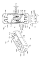
- FIG. 1 It is a perspective view of the charging system of the portable terminal device by Embodiment 1 of this invention.
- (A) And (b) is a perspective view of the charge cable of the portable terminal device by Embodiment 1 of this invention. It is a perspective view which shows the charging cable of the portable terminal device by Embodiment 1 of this invention, disassembling a part of terminal housing. It is a perspective view of the charging cable of the portable terminal device by Embodiment 1 of this invention before mounting
- (A), (b) and (c) are the perspective view of the charging stand in the charging system of the portable terminal device by Embodiment 1 of this invention, a top view, and a front view.
- (A) And (b) is a perspective view of a portable terminal device.
- (A), (b) and (c) are the front view, back view, and bottom view of a portable terminal device. It is the rear view which removed the rear cover of the portable terminal device, and was seen. It is a front view which partially fractures
- (A) is a figure which partially shows the charging cable of the charging stand / portable terminal device in the charging system of the portable terminal device by Embodiment 1 of this invention before mounting to a portable terminal device / before mounting
- FIG. B is a partial view of a charging base / charging terminal of the portable terminal device in the charging system of the portable terminal device according to Embodiment 1 of the present invention after the portable terminal device is mounted / mounted on the portable terminal device.
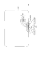
- FIG. It is an electric circuit diagram of the charging stand in the charging system of the portable terminal device by Embodiment 1 of this invention. It is an electric circuit diagram of the charging cable of the portable terminal device by Embodiment 1 of this invention. It is a flowchart for demonstrating operation
- a charging system for a portable terminal device includes a charging base on which the portable terminal device is detachably mounted, and a charging cable that is detachably attached to the portable terminal device.
- the charging stand includes a terminal mounting portion on which the mobile terminal device is mounted, and a base charging terminal that is connected to a charge terminal of the mobile terminal device mounted on the terminal mounting portion and charges the mobile terminal device.
- the charging cable includes a cable charging terminal that charges the portable terminal device by connecting to the charged terminal of the attached portable terminal device.
- the charging cable according to the embodiment of the present invention includes a terminal housing having a cable charging terminal.
- a terminal housing having a cable charging terminal is detachably attached to the mobile terminal device, and the cable charging terminal abuts on a terminal to be charged of the attached mobile terminal device, so that the mobile terminal device is charged.
- the terminal housing further includes a suction portion.
- the adsorbing part adsorbs to the adsorbed part provided in the mobile terminal device so as to maintain the attached state when the adsorbing part is attached to the mobile terminal device.
- the attracting portion is made of a magnet when the attracted portion of the mobile terminal device is made of a metal plate, and is made of a metal plate or magnet when the attracted portion of the mobile terminal device is made of a magnet.
- a charging system for a portable terminal device charges a tablet-type portable terminal device used in a self-ordering system that is an aspect of a POS (Point Of Sales) system. It is a system that performs.
- POS Point Of Sales
- the charging system includes a charging stand 100 and a charging cable 200.
- a plug connector (described later) of the charging cable 200 is connected to a receptacle connector (described later) of the charging stand 100.
- the charging cable 200 is attached to one mobile terminal device 600, and the mobile terminal device 600 is charged.
- the charging stand 100 incorporates an AC (Alternating Current) adapter, which will be described later, and is connected to a commercial power source via an AC cable and an AC plug. However, the AC cable and the AC plug are not shown in FIG. ing. In addition, as will be described later, one of the two portable terminal devices 600 mounted on the charging stand 100 is not supplied with a charging voltage and is not charged.
- AC Alternating Current
- the charging cable 200 includes a terminal housing 220 provided with a cable charging terminal, a cable portion 210, and a plug connector 230.
- the terminal housing 220 has an L-shaped cross section, and four contact pins 201 are provided on the base portion 221a as cable charging terminals.
- the four contact pins 201 are arranged on the base 221a at a predetermined interval on a straight line so as to correspond to the position of the charged terminal 601 (FIG. 8C) of the mobile terminal device 600. Further, the four contact pins 201 are arranged (12V, DETECT1, DETECT2) so as to match the arrangement (12V, DETECT1, DETECT2, GND) of the charged terminal 601 (FIG. 8C) of the mobile terminal device 600. , GND).
- Two contact pins 201 (12V, GND) are used for supplying a charging voltage, and the other two contact pins 201 (DETECT1, DETECT2) are portable terminal devices to which a terminal housing 220 (charging cable 200) is attached. Used for 600 detection.
- the contact pin 201 is a so-called pogo pin (registered trademark) type or a probe type. That is, the contact pin 201 has an elastic portion (not shown) such as a spring for the upper end to sink from the original position when a force is applied from above and the upper end to return to the original position when the force is removed. Yes.
- the base 221a is provided with a guide convex portion 224 corresponding to the terminal adjacent concave portion 604 (FIG. 8C) provided on the bottom surface of the portable terminal device 600.
- the guide convex portion 224 is a guide portion when the terminal housing 220 is set on the mobile terminal device 600.
- a contact surface 222 that contacts the back surface of the mobile terminal device 600 is provided on the standing portion 221b that stands from the base portion 221a of the terminal housing 220.
- ribs 223 that are in contact with the back surface of the mobile terminal device are provided in the same manner as the contact surface 222.
- a magnet 226 (FIG. 3) is attached as an attracting portion on the back side of the contact surface 222.
- the raised portion 221b is provided with a locking convex portion 225 corresponding to the back surface concave portion 605 (FIG. 4) on the back surface of the mobile terminal device 600.
- the locking projection 225 engages with the back surface recess 605 on the back surface of the mobile terminal device 600, so that the terminal housing 220 is connected to the mobile terminal device 600. To prevent it from slipping along the back side.
- FIG. 3 is a perspective view of the charging cable 200.
- the terminal housing 220 is in a state in which the bottom cover 221d and the back cover 221c are removed.
- a magnet 226 is attached inside the terminal housing 220.
- the magnet 226 contacts the charging cable 200 by a magnetic force generated between the terminal housing 220 of the charging cable 200 and the metal plate 606 provided in the casing of the portable terminal device 600 when the terminal housing 220 is attached to the portable terminal device 600.
- the contact of the pin (cable charging terminal) 201 with the charged terminal 601 (FIG. 8C) of the mobile terminal device 600 is maintained.
- the metal plate 606 provided in the portable terminal device 600 is made of metal, for example, iron that is attracted by the magnet 226.
- the attachment of the terminal housing 220 of the charging cable 200 to the portable terminal device 600 is performed as follows.
- the base 221 a of the terminal housing 220 is brought into contact with the bottom surface of the portable terminal device 600 on which the charged terminal 601 (FIG. 8C) is provided.
- the guide convex portion 224 of the base portion 221a is made to correspond to the terminal adjacent concave portion 604 (FIG. 8C) on the bottom surface of the mobile terminal device 600.
- the standing portion 221b of the terminal housing 220 is brought into contact with the back surface of the mobile terminal device 600 as shown in FIG.
- the magnet 226 is provided inside the standing portion 221b of the terminal housing 220 as indicated by a broken line in the figure.
- a metal plate 606 is provided in the casing of the mobile terminal device 600 as indicated by a broken line in the figure. The magnetic force generated between the magnet 226 and the metal plate 606 maintains the contact of the charging terminal of the terminal housing 220 with the charging terminal surface of the mobile terminal device.
- a locking projection 225 is provided on the standing portion 221 b of the terminal housing 220.
- a back surface recess 605 is provided on the back surface of the mobile terminal device 600. Engagement of the locking projection 225 with the back recess 605 prevents the terminal housing 220 from coming off due to slippage along the back of the mobile terminal device 600.
- the charging stand 100 includes two terminal mounting portions 112A and 112B and three display portions (LED (Light Emitting Diode)) 105A, 105B, 105C and one receptacle connector 101C are provided.
- the charging stand 100 incorporates an AC adapter, which will be described later, and is connected to a commercial power source via an AC cable and an AC plug, but the AC cable and the AC plug are not shown in FIG.
- the terminal mounting portions 112A and 112B are each provided with four contact pins 101A and 101B as stand charging terminals. Two of the contact pins (12V, GND) are used for supplying the charging voltage, and the other two (DETECT1, DETECT2) are used for detection of the mounted mobile terminal device 600.
- the four contact pins 101A and 101B are arranged on the straight line at predetermined intervals so as to correspond to the positions of the terminals to be charged 601 (FIG. 8C) of the mobile terminal device 600, respectively, on the terminal mounting portions 112A and 112B. Has been placed.
- the four contact pins 101A and 101B are arranged (12V, DETECT1) so as to match the arrangement (12V, DETECT1, DETECT2, GND) of the charged terminal 601 (FIG. 8C) of the mobile terminal device 600. , DETECT2, GND).
- the arrangement and arrangement of the four contact pins 201 of the terminal housing 220 of the charging cable 200 and the arrangement and arrangement of the four contact pins 101A and 101B of the two terminal mounting portions 112A and 112B of the charging stand 100 are the same. is there.
- the contact pins 101 ⁇ / b> A and 101 ⁇ / b> B are of the so-called pogo pin (registered trademark) type or probe type, like the contact pin (cable charging terminal) 201 of the charging cable 200. That is, the contact pins 101A and 101B have an elastic portion (not shown) such as a spring for the upper end to sink from the original position when a force is applied from above and the upper end to return to the original position when the force is removed. is doing. In this example, in particular, the same components as the contact pins (cable charging terminals) 201 are used as the contact pins 101A and 101B.
- the terminal mounting portions 112A and 112B are also provided with guide end portions 115A and 115B for guiding the mobile terminal device when the mobile terminal device 600 is placed.
- the guide end portions 115 ⁇ / b> A and 115 ⁇ / b> B have shapes corresponding to the outer shapes of both side portions of the portable terminal device 600 placed vertically.
- the portable terminal device 600 is placed vertically so that the display surface faces one direction.
- the charged terminal 601 of the mobile terminal device 600 matches the assignment of 12V, DETECT1, DETECT2, and GND with respect to the contact pins 112A and 112B.
- guide protrusions 114A and 114B corresponding to the terminal adjacent recesses 604 on the bottom surface of the mobile terminal device 600 are provided.
- the portable terminal device 600 is mounted on the charging stand 100 and charged as follows. That is, the portable terminal device 600 is temporarily held above the terminal mounting portion 112A or 112B so as to match the shape of the guide end portion 115A or 115B of the terminal mounting portion 112A or 112B, and then released.
- the opened mobile terminal device 600 sinks into the terminal mounting portion 112A or 112B by its own weight.
- the terminal 601 to be charged of the mobile terminal device 600 and the contact pin 101A or 101B provided on the terminal mounting portion 112A or 112B come into contact with each other, and the mobile terminal device 600 is charged.
- Display units (LEDs) 105A, 105B, and 105C correspond to the charging ports 1, 2, and 3, respectively.
- the charging port 1 is a terminal mounting portion 112A provided with a contact pin (base charging terminal) 101A.
- the charging port 2 is a terminal mounting portion 112B provided with a contact pin (base charging terminal) 101B.
- the charging port 3 is a terminal housing 220 provided with a charging cable 200 connected to the charging base 100 via the receptacle connector 101C, more specifically, a contact pin (cable charging terminal) 201.
- Display units 105A, 105B, and 105C indicate charging voltage supply states of charging ports 1, 2, and 3. Specifically, the lighting of the display unit indicates that the charging voltage is supplied, and the extinguishing lamp indicates that the charging voltage is cut off.
- the portable terminal device 600 which is an object of the charging system and the charging cable of the present embodiment, has a display 600td with a touch panel on the front surface.
- the mobile terminal device 600 has a resin rear panel 600r on the back surface, and has a charged terminal 601 and a terminal adjacent recess 604 on the bottom surface.
- the charged terminal 601 includes a charging terminal (12V, GND) and a detection terminal (DETECT1, DETECT2) of the mobile terminal device.
- a metal plate 606 attracted to the magnet 226 built in the terminal housing 220 of the charging cable 200 is attached to the inner surface of the rear panel 600r. In FIG. 9, some of the mounted objects other than the metal plate 606 are not shown.
- FIGS. 10 and 11 are diagrams showing a state of contact or contact between the charged terminal 601 of the portable terminal device 600 and the contact pin 101A or 101B of the charging stand 100.
- FIG. FIG. 10 is a view before contact
- FIG. 11 is a view after contact.
- FIG. 12 and FIG. 13 are diagrams showing a state of contact or contact between the charged terminal 601 of the portable terminal device 600 and the contact pin 201 of the charging cable 200.
- FIG. 12 is a view before contact
- FIG. 13 is a view after contact.
- FIG. 14 (a) and 14 (b) are enlarged views showing the state of contact between the charged terminal 601 of the portable terminal device 600 and the contact pin of the charging stand 100 or the charging cable 200.
- FIG. 14A is a diagram before contact
- FIG. 14B is a diagram after contact.
- the contact pin 101A or 101B (or contact pin 201). ) Is pushed by the charged terminal 601 of the belt terminal device 600.
- the contact pin 101A or 101B (or the contact pin 201) sinks from the position C1 to the position C2.
- the contact pins 101 ⁇ / b> A and 101 ⁇ / b> B and the contact pin 201 have the same stroke amount from the original position to the position where the contact pin 101 sunk by the charged terminal 601 of the band terminal device 600.
- the location where the charged terminal 601 of the portable terminal device 600 abuts on the contact pin 101A or 101B of the charging stand 100 and the location where the contact pin 201 of the charging cable 200 abuts are the same. is there. Therefore, the contact between the charged terminal 601 of the mobile terminal device 600 and the contact pin 101A or 101B of the charging stand 100 and the contact between the charged terminal 601 of the mobile terminal device 600 and the contact pin 201 of the charging cable 200 are as follows: The same is done.
- AC adapter 700 connected to a commercial power source converts AC 100V to DC 12V.
- the AC adapter 700 is built in the charging stand 100, but the AC adapter 700 may be provided outside the charging stand 100.
- the DC / DC converter 106 converts DC12V to DC3.3V.
- the charging stand 100 includes charging ports 1 and 2 and a receptacle connector corresponding to the charging port 3.
- the charging port 1 is a terminal mounting portion 112A provided with a contact pin (base charging terminal) 101A.
- the charging port 2 is a terminal mounting portion 112B provided with a contact pin (base charging terminal) 101B.
- the charging port 3 is a terminal housing 220 provided with a charging cable 200 connected to the charging base 100 via the receptacle connector 101C, more specifically, a contact pin (cable charging terminal) 201.
- the contact pins 101A and 101B of the charging ports 1 and 2 include “12V”, “GND”, “DETECT1”, and “DETECT2” terminals, respectively.
- the receptacle connector 101C corresponding to the charging port 3 also includes “12V”, “GND”, “DETECT1”, and “DETECT2” terminals.
- the charging voltage is supplied to the “12V” terminal and the “GND” terminal of the contact pins 101A and 101B and the receptacle connector 101C.
- the control unit 102 of the charging stand 100 controls the charging voltage switching circuits 103A, 103B, and 103C to turn on / off the charging voltage of 12V.
- the “DETECT1” terminal and the “DETECT2” terminal of the contact pins 101A and 101B and the receptacle connector 101C are used for detection of the mobile terminal device 600.
- 3.3V is supplied to the “DETECT1” terminal.
- the “DETECT1” terminal and the “DETECT2” terminal in the charged terminal 601 (FIG. 8C) of the portable terminal device 600 are electrically connected in the portable terminal device 600. Therefore, when the mobile terminal device 600 is placed on the terminal mounting portions 112A and 112B of the charging stand 100, or the terminal housing 220 of the charging cable 200 is attached to the mobile terminal device 600, the contact pins 101A and 101B are connected.
- 3.3V of the “DETECT1” terminal in the receptacle connector 101C is output to the “DETECT2” terminal.
- the control unit 102 of the charging stand 100 determines that the mobile terminal device 600 has been detected when the terminal that is normally at the Low level at the “DETECT2” terminal detects the High level (3.3 V), and the charging voltage switching circuit 103A. , 103B or 103C is turned on to supply a charging voltage.
- the LED driving circuit 104A, 104B or 104C is controlled to light the LED 105A, 105B or 105C.
- the control unit 102 determines that the mobile terminal device 600 is no longer detected, and turns off the charging voltage switching circuit 103A, 103B or 103C to turn off the charging voltage. Cut off.
- the LED driving circuit 104A, 104B or 104C is controlled to turn off the LED 105A, 105B or 105C.
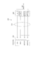
- FIG. 16 is a circuit diagram of the charging cable 200
- the plug connector 230 of the charging cable 200 is connected to the receptacle connector 101 ⁇ / b> C (FIG. 15) of the charging stand 100.
- a contact pin (cable charging terminal) 201 is connected to the plug connector 230 via a cable portion 210.
- the terminal housing 220 provided with the contact pins 201 constitutes the charging port 3.
- the contact pin 201 of the charging port 3 includes “12V”, “GND”, “DETECT1”, and “DETECT2” terminals.
- step S1 of FIG. 17 the control unit 102 of the charging stand 100 determines whether or not the mobile terminal device 600 has been detected.
- the process proceeds to step S2.
- the process proceeds to step S6.
- step S ⁇ b> 2 the control unit 102 of the charging stand 100 determines whether charging is being performed at two charging ports other than the charging port that has detected the mobile terminal device 600. If the other two charging ports are being charged (YES in step S2), the process proceeds to step S3. On the other hand, when the other two charging ports are not being charged (NO in step S2), the process proceeds to step S5.
- the reason why it is determined whether or not charging is being performed at two charging ports other than the charging port that has detected the portable terminal device 600 is that the AC adapter 700 built in the charging stand 100 is equivalent to two portable terminals. This is because the device has only a charging current supply capability, that is, only two portable terminal devices can be charged at the same time.
- step S3 it is determined whether or not the charging port 2 is charging.
- the process proceeds to step S4.
- the charging port 2 is not being charged (NO in step S3), the process proceeds to step S6.
- step S4 the charging voltage to the charging port 2 is cut off and the process proceeds to step S5. That is, in step S ⁇ b> 4, the portable terminal device 600 is placed on both the charging ports 1 and 2, and the charging port 3 is attached to the portable terminal device 600. That is, all the charging ports 1 to 3 are full. In this example, since there is only a charging capacity for two charging ports, the charging voltage to the charging port 2 among the charging ports 1 to 3 is cut off, and the portable terminal device 600 placed on the charging port 2 is connected to the portable terminal device 600. Stop charging.
- step S5 the charging voltage is supplied to the charging port detected by the portable terminal device 600, and the process proceeds to step S6.
- step S6 it is determined whether there is a charging port that no longer detects the mobile terminal device 600. If there is a charging port that no longer detects the mobile terminal device 600 (YES in step S6), the process proceeds to step S7. On the other hand, when there is no charging port that no longer detects the mobile terminal device 600 (NO in step S6), the process returns to step S1.
- step S7 the charging voltage to the charging port that no longer detects the mobile terminal device 600 is cut off, and the process proceeds to step S8.
- step S8 it is determined whether or not the portable terminal device 600 is detected at the charging port 2.
- the process proceeds to step S9.
- the portable terminal device 600 is not detected at the charging port 2 (NO in step S8), the process returns to step S1.
- step S9 it is determined whether or not the portable terminal device 600 is being charged at the charging port 2. If the portable terminal device 600 is being charged at the charging port 2 (YES in step S9), the process returns to step S1. On the other hand, when the portable terminal device 600 is not being charged at the charging port 2 (NO in step S9), the process proceeds to step S10.
- step S10 the charging voltage is supplied to the charging port 2, and the process returns to step S1.
- the charging stand 100 has the two charging ports 1 and 2, that is, the terminal mounting portions 112A and 112B, but there may be one terminal mounting portion. Or the charging stand may have three or more terminal mounting parts.
- the charging current supply capability of the AC adapter 700 (charging current supply source) can be supplied to the number of portable terminal devices corresponding to the number of terminal mounting units.
- one charging port (charging port corresponding to the terminal mounting portions 112A and 112B) that does not supply the charging voltage when the number of mobile terminal devices of (number of terminal mounting portions 112A and 112B + 1) is detected is determined. Keep it.
- the mobile terminal device set on the charging cable with the AC adapter having only the charging current supply capability for the number of mobile terminal devices mounted on the charging stand. Can be charged.
- the charging current supply capability of the AC adapter may be supplied to at least the number of all charging ports including the charging port of the charging cable.
- step S21 of FIG. 18 the control unit 102 of the charging stand 100 determines whether or not a mobile terminal device has been detected. When the mobile terminal device is detected (YES in step S21), the process proceeds to step S22. On the other hand, when the mobile terminal device is not detected (NO in step S21), the process proceeds to step S23.
- step S22 the charging voltage is supplied to the charging port that has detected the mobile terminal device, and the process proceeds to step S23.
- step S23 it is determined whether there is a charging port that no longer detects the mobile terminal device. If there is a charging port that no longer detects the mobile terminal device (YES in step S23), the process proceeds to step S24. On the other hand, when there is no charging port that no longer detects the mobile terminal device (NO in step S23), the process returns to step S21.
- step S24 the charging voltage to the charging port that no longer detects the mobile terminal device is cut off, and the process returns to step S21.
- Embodiment 2 of the present invention is implemented in that the charging base does not have a charging port 3 and a receptacle connector for connecting a charging cable, and that the charging cable charges the mobile terminal device without going through the charging base. Different from Form 1.
- the contact between the charged terminal of the mobile terminal device and the contact pin of the charging stand and the contact between the charged terminal of the mobile terminal device and the contact pin of the terminal housing of the charging cable are The same is done.
- the location where the terminal to be charged of the mobile terminal device contacts the contact pin of the charging stand is the same as the location of contact of the contact pin of the terminal housing of the charging cable.
- the mobile terminal device charging system includes a charging stand 100 '(FIG. 19) and a charging cable (FIG. 20).
- the charging stand 100 ′ of the present embodiment does not have the charging port 3. That is, it does not have a receptacle connector, a charging voltage switching circuit, an LED driving circuit, and a display unit (LED) for the charging port 3. Since the other configuration of the charging stand 100 ′ is the same as that of the first embodiment, detailed description thereof is omitted.
- the charging stand 100 ′ includes charging ports 1 and 2.
- the charging ports 1 and 2 are terminal mounting portions 112A ′ and 112B ′ provided with contact pins (base charging terminals) 101A ′ and 101B ′, respectively.
- the shape and structure of the charging base 100 ′, the terminal mounting portions 112A ′ and 112B ′, and the contact pins 101A ′ and 101B ′ are the same as those of the charging base, the terminal mounting portion, and the contact pins of the first embodiment. 6, 10, 11, 14, and the like are referred to.
- An AC adapter 700 'connected to a commercial power source (not shown) converts AC 100V into DC 12V.
- the DC / DC converter 106 'converts DC 12V into DC 3.3V.
- the contact pins 101A 'and 101B' of the charging ports 1 and 2 include "12V”, “GND”, “DETECT1”, and “DETECT2" terminals, respectively.
- the charging voltage is supplied to the “12V” terminal and the “GND” terminal of the contact pins 101A ′ and 101B ′.
- the control unit 102 ′ of the charging stand 100 ′ controls the charging voltage switching circuits 103 ⁇ / b> A ′ and 103 ⁇ / b> B ′ to turn on / off the charging voltage of 12V.
- the “DETECT1” terminal and the “DETECT2” terminal of the contact pins 101A ′ and 101B ′ are used for detection of the portable terminal device 600 shown in FIGS. 3.3V is supplied to the “DETECT1” terminal.
- the “DETECT1” terminal and the “DETECT2” terminal in the charged terminal 601 (FIG. 8C) of the portable terminal device 600 are electrically connected in the portable terminal device 600. Accordingly, when the portable terminal device 600 is placed on the terminal mounting portions 101A ′ and 101B ′ of the charging stand 100 ′, 3.3V of the “DETECT1” terminal in the contact pins 101A ′ and 101B ′ is changed to the “DETECT2” terminal. Will be output.
- the control unit 102 ′ of the charging stand 100 ′ determines that the mobile terminal device 600 has been detected when the terminal that is normally at the low level in the “DETECT2” terminal detects the high level (3.3 V), and opens and closes the charging voltage.
- the circuits 103A ′ and 103B ′ are turned on to supply a charging voltage.
- the LED driving circuits 104A 'and 104B' are controlled to light the LEDs 105A 'and 105B'.
- the control unit 102 ′ determines that the mobile terminal device 600 is not detected, and turns off the charging voltage switching circuits 103A ′ and 103B ′ to perform charging. Cut off the voltage.
- the LED driving circuits 104A 'and 104B' are controlled to turn off the LEDs 105A 'and 105B'.
- step S21 of FIG. 18 the control unit 102 'of the charging stand 100' determines whether or not a mobile terminal device has been detected.
- the process proceeds to step S22.
- the process proceeds to step S23.
- step S22 the charging voltage is supplied to the charging port that has detected the mobile terminal device, and the process proceeds to step S23.
- step S23 it is determined whether there is a charging port that no longer detects the mobile terminal device. If there is a charging port that no longer detects the mobile terminal device (YES in step S23), the process proceeds to step S24. On the other hand, when there is no charging port that no longer detects the mobile terminal device (NO in step S23), the process returns to step S21.
- step S24 the charging voltage to the charging port that no longer detects the mobile terminal device is cut off, and the process returns to step S21.
- FIG. 20 is a diagram illustrating a circuit configuration of the charging cable 200 ′ according to the present embodiment.
- the AC adapter 800 converts AC100V to DC12V.
- the DC / DC converter 206 converts DC12V into DC3.3V.
- the charging cable 200 ' has a single charging port 3'.
- the charging port 3 ' is a terminal housing 220' provided with a contact pin (cable charging terminal) 201 '. Since the shape and structure of the terminal housing 220 ′ and the contact pin 201 ′ are the same as those of the terminal housing and the contact pin of the first embodiment, refer to FIG. 1 to FIG. 5, FIG. To do.
- a magnet is attached to the inside of the terminal housing 220 'as an attracting portion.
- the charging port 3 ′ includes “12V”, “GND”, “DETECT1”, and “DETECT2” terminals.
- the charging voltage is supplied to the “12V” terminal and the “GND” terminal of the contact pin 201 ′.
- the control unit 202 of the charging cable 200 ′ controls the charging voltage switching circuit 203 to turn on / off the charging voltage of 12V.
- the “DETECT1” terminal and the “DETECT2” terminal in the charged terminal 601 (FIG. 8C) of the portable terminal device 600 are electrically connected in the portable terminal device 600. Therefore, by attaching the terminal housing 220 ′ of the charging cable 200 ′ to the portable terminal device 600, 3.3V of the “DETECT1” terminal in the contact pin 201 ′ is output to the “DETECT2” terminal.
- the control unit 202 of the charging cable 200 ′ determines that the portable terminal device 600 has been detected when the terminal that is normally at the Low level in the “DETECT2” terminal detects the High level (3.3 V), and the charging voltage switching circuit 203 is turned on to supply a charging voltage. At the same time, the LED drive circuit 204 is controlled to light the LED 205.
- control unit control unit 202 determines that the mobile terminal device 600 is not detected, and turns off the charging voltage switching circuit 203 to cut off the charging voltage. .
- the LED drive circuit 204 is controlled to turn off the LED 205.
- step S31 of FIG. 21 the control unit 202 of the charging cable 200 'determines whether or not a portable terminal device is detected in the charging port 3'.
- the process proceeds to step S32.
- the process proceeds to step S33.
- step S32 the charging voltage is supplied to the charging port 3 'detected by the portable terminal device, and the process proceeds to step S33.
- step S33 it is determined whether or not the portable terminal device is no longer detected at the charging port 3 '. If the mobile terminal device is no longer detected (YES in step S33), the process proceeds to step S34. On the other hand, when the mobile terminal device is detected (NO in step S33), the process returns to step S31.
- step S34 the charging voltage to the charging port 3 'that no longer detects the mobile terminal device is cut off, and the process returns to step S31.
- the charging stand 100 ′ includes the two terminal mounting portions 112A ′ and 112B ′.
- the number of the terminal mounting portions may be one, or three or more. Good.
- the invention of the second embodiment it is possible to provide a charging system for a mobile terminal device that can be used while being charged even if the mobile terminal device is placed on a charging stand and charged.
- the present invention is not limited to the embodiment described above.
- the metal plate is provided as the attracted portion in the mobile terminal device, while the magnet as the attracting portion is provided in the terminal housing of the charging cable.
- the metal plate as the attracting portion may be provided in the terminal housing of the charging cable.
- the magnet as the attracting portion may also be provided in the terminal housing of the charging cable.
- the magnetic pole arrangement is such that a magnetic force attracting the magnets is generated. That is, the N pole of the magnet of the mobile terminal device and the S pole of the magnet of the terminal housing face each other, or the S pole of the magnet of the mobile terminal device and the N pole of the magnet of the terminal housing face each other. To do.
- the base charging terminal and the cable charging terminal are contact pins, but the base charging terminal and / or the cable charging terminal may be a leaf spring-like terminal. Good.
Landscapes
- Engineering & Computer Science (AREA)
- Power Engineering (AREA)
- Theoretical Computer Science (AREA)
- Computer Hardware Design (AREA)
- Human Computer Interaction (AREA)
- Physics & Mathematics (AREA)
- General Engineering & Computer Science (AREA)
- General Physics & Mathematics (AREA)
- Signal Processing (AREA)
- Charge And Discharge Circuits For Batteries Or The Like (AREA)
- Telephone Set Structure (AREA)
Abstract
携帯端末装置を取り出し可能に搭載する充電台と、携帯端末装置に取り外し可能に装着される充電ケーブルとを有している。充電台は、携帯端末装置を搭載する端末搭載部と、端末搭載部に搭載された携帯端末装置の被充電端子に当接して携帯端末装置に充電を行う台充電端子を備えている。充電ケーブルは、装着された携帯端末装置の被充電端子に当接して携帯端末装置に充電を行うケーブル充電端子を備えている。
Description
本発明は、携帯端末装置の充電システムおよび充電ケーブルに関する。
携帯端末装置は、内蔵するバッテリ(二次電池)を充電する必要がある。携帯端末装置のバッテリの充電は、1台もしくは複数台の携帯端末装置の端末搭載部を有する充電台(クレードル)に載置して行われる。
この種の充電台は、例えば、特許文献1に開示されている。特許文献1に開示された充電台は、携帯端末装置を取り出し可能に搭載する端末搭載部を有している。
情報処理装置の類である携帯端末装置は、通常、手で保持しながら、ディスプレイの表示を視認しつつ、入力操作を行って処理結果を視認するなどして使用する。そのような携帯端末装置を、特許文献1に開示されたような充電台によって充電中は、ディスプレイの表示を視認することは難しく、入力操作を行うことはさらに難しい。即ち、携帯端末装置を充電台で充電している時は、携帯端末装置を使用して何等かの作業を行うことは困難である。
そのため、充電台に載置して充電する携帯端末装置の場合、携帯端末装置を使用しての作業中にバッテリが切れそうになると、その作業を中断した上で、携帯端末装置を充電台に載置し、バッテリの充電を開始せざるを得ない。
本発明の目的は、上記課題を解決するための技術を提供することにあり、充電を行いながら携帯端末装置を使用することを可能にする携帯端末装置の充電システムを提供することである。
本発明の一実施態様によれば、携携帯端末装置を取り出し可能に搭載する充電台と、携帯端末装置に取り外し可能に装着される充電ケーブルとを有し、前記充電台は、携帯端末装置を搭載する端末搭載部と、該端末搭載部に搭載された携帯端末装置の被充電端子に当接して携帯端末装置に充電を行う台充電端子を備え、前記充電ケーブルは、装着された携帯端末装置の被充電端子に当接して携帯端末装置に充電を行うケーブル充電端子を備えていることを特徴とする携帯端末装置の充電システムが得られる。
本発明の他の実施態様によれば、携帯端末装置に取り外し可能に装着され、装着された携帯端末装置の被充電端子に当接して携帯端末装置に充電を行うケーブル充電端子と、前記ケーブル充電端子が設けられ、携帯端末装置に取り外し可能に装着される端子ハウジングとを備え、前記端子ハウジングは、携帯端末装置に装着されたときに装着状態を維持すべく、携帯端末装置に備えられた被吸着部に対して吸着する吸着部を備え、前記吸着部は、携帯端末装置の被吸着部が金属板から成る場合は、磁石から成り、携帯端末装置の被吸着部が磁石から成る場合は、金属板または磁石から成ることを特徴とする携帯端末装置の充電ケーブルが得られる。
本発明によれば、充電を行いながら携帯端末装置を使用することを可能にする携帯端末装置の充電システムが得られる。
本発明の実施形態による携帯端末装置の充電システムは、携携帯端末装置を取り出し可能に搭載する充電台と、携帯端末装置に取り外し可能に装着される充電ケーブルとを有している。充電台は、携帯端末装置を搭載する端末搭載部と、端末搭載部に搭載された携帯端末装置の被充電端子に接続して携帯端末装置に充電を行う台充電端子を備えている。充電ケーブルは、装着された携帯端末装置の被充電端子に接続して携帯端末装置に充電を行うケーブル充電端子を備えている。
また、本発明の実施形態による充電ケーブルは、ケーブル充電端子を有する端子ハウジングを備えている。ケーブル充電端子を有する端子ハウジングは、携帯端末装置に取り外し可能に装着され、装着された携帯端末装置の被充電端子にケーブル充電端子が当接し、携帯端末装置に充電が行われる。端子ハウジングはさらに、吸着部を備えている。吸着部は、携帯端末装置に装着されたときに装着状態を維持すべく、携帯端末装置に備えられた被吸着部に対して吸着する。吸着部はさらに、携帯端末装置の被吸着部が金属板から成る場合は、磁石から成り、携帯端末装置の被吸着部が磁石から成る場合は、金属板または磁石から成る。
本発明によれば、上記の構成により、充電台に載置して充電する携帯端末装置であっても、充電を行いながら使用することが可能になる。
以下、図面を参照して、本発明による携帯端末装置の充電システムならびに充電ケーブルのより具体的な実施形態を説明する。
[実施形態1]
図1~図17を参照すると、本発明の実施形態1による携帯端末装置の充電システムは、POS(Point Of Sales)システムの一態様であるセルフオーダリングシステムに用いられるタブレットタイプの携帯端末装置に充電を行うシステムである。
図1~図17を参照すると、本発明の実施形態1による携帯端末装置の充電システムは、POS(Point Of Sales)システムの一態様であるセルフオーダリングシステムに用いられるタブレットタイプの携帯端末装置に充電を行うシステムである。
図1を参照すると、本充電システムは、充電台100と、充電ケーブル200とを有している。
充電台100には、2台の携帯端末装置600が縦置きで載置されている。充電台100の後述するレセプタクルコネクタには、充電ケーブル200の後述するプラグコネクタが接続されている。充電ケーブル200は、1台の携帯端末装置600に装着され、携帯端末装置600への充電が行われている。
尚、充電台100は、後述するAC(Alternating Current)アダプタを内蔵し、ACケーブルとACプラグを介して商用電源に接続されるが、図1においては、ACケーブルとACプラグの図示を省略している。また、後述するが、充電台100に搭載されている2台の携帯端末装置600のうちの1台には、充電電圧は供給されておらず、充電は行われていない。
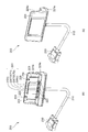
図2(a)および(b)をさらに参照すると、充電ケーブル200は、ケーブル充電端子が設けられた端子ハウジング220と、ケーブル部210と、プラグコネクタ230とを有している。
端子ハウジング220は断面L字状を呈しており、その基部221aには、ケーブル充電端子として、4本のコンタクトピン201が設けられている。4本のコンタクトピン201は、基部221aに、携帯端末装置600の被充電端子601(図8(c))の位置に対応するように、直線上に所定の間隔で配置されている。また、4本のコンタクトピン201は、携帯端末装置600の被充電端子601(図8(c))の配列(12V、DETECT1、DETECT2、GND)に合致するように、配列(12V、DETECT1、DETECT2、GND)されている。
2本のコンタクトピン201(12V、GND)は、充電電圧供給に用いられ、他の2本のコンタクトピン201(DETECT1、DETECT2)は、端子ハウジング220(充電ケーブル200)が装着された携帯端末装置600の検知に用いられる。本例において、コンタクトピン201は、いわゆるポゴピン(登録商標)タイプまたはプローブタイプである。即ち、コンタクトピン201は、上から力が加わると上端が原位置から下に沈み、力が取り去られると上端が原位置に復帰するためのバネ等の弾性部(図示せず)を有している。
また、基部221aには、携帯端末装置600の底面に設けられた端子隣接凹部604(図8(c))に対応するガイド凸部224が設けられている。ガイド凸部224は、携帯端末装置600に端子ハウジング220をセットする際のガイド部となっている。
端子ハウジング220の基部221aから立設する立設部221bには、携帯端末装置600の背面と当接する当接面222が設けられている。当接面222の両側には、当接面222と同様に携帯端末装置の背面と当接するリブ223が設けられている。端子ハウジング220の内部のうち、当接面222の裏側には、吸着部として磁石226(図3)が取り付けられている。
また、立設部221bには、携帯端末装置600の背面の背面凹部605(図4)に対応する係止凸部225が設けられている。係止凸部225は、充電ケーブル200の端子ハウジング220が携帯端末装置600に装着された時に、携帯端末装置600の背面の背面凹部605に係合することにより、端子ハウジング220が携帯端末装置600の背面に沿ってズレて外れてしまうことを防止する。
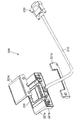
図3は、充電ケーブル200の斜視図であり、同図において、端子ハウジング220は、底面カバー221dと背面カバー221cを外した状態である。
図3、図4および図5をさらに参照すると、端子ハウジング220の内部には、磁石226が取り付けられている。磁石226は、充電ケーブル200の端子ハウジング220が携帯端末装置600に装着された時に、携帯端末装置600の筐体内に設けられた金属板606との間に発生する磁力により、充電ケーブル200のコンタクトピン(ケーブル充電端子)201の携帯端末装置600の被充電端子601(図8(c))への接触を維持する。尚、本例において、携帯端末装置600内に設けられた金属板606は、磁石226によって引き寄せられる金属製、例えば鉄製である。
携帯端末装置600への充電ケーブル200の端子ハウジング220の装着は、以下のようにして行う。
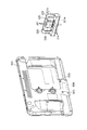
図4に示すように、端子ハウジング220の基部221aを、携帯端末装置600の被充電端子601(図8(c))が設けられている底面に当接させる。このとき、基部221aのガイド凸部224を、携帯端末装置600の底面の端子隣接凹部604(図8(c))に対応させる。これと共に、端子ハウジング220の立設部221bを、図5に示すように携帯端末装置600の背面に当接させる。
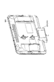
前述したように、端子ハウジング220の立設部221bの内部には、図中破線で示すように磁石226が設けられている。一方、携帯端末装置600の筐体内には、図中破線で示すように金属板606が設けられている。磁石226と金属板606との間に生ずる磁力により、端子ハウジング220の充電端子の携帯端末装置の充電端子面への当接が維持される。また、端子ハウジング220の立設部221bには、係止凸部225が設けられている。一方、携帯端末装置600の背面には、背面凹部605が設けられている。係止凸部225が背面凹部605に係合することにより、端子ハウジング220が、携帯端末装置の600背面に沿ってズレることによって外れてしまうことが防止される。
図6(a)、(b)および(c)をさらに参照すると、充電台100には、2つの端末搭載部112A、112Bと、3つの表示部(LED(Light Emitting Diode))105A、105B、105Cと、1つのレセプタクルコネクタ101Cとが設けられている。尚、充電台100は、後述するACアダプタを内蔵し、ACケーブルとACプラグを介して商用電源に接続されるが、図6においてはACケーブルとACプラグの図示を省略している。
端末搭載部112A、112Bにはそれぞれ、台充電端子として、4本のコンタクトピン101A、101Bが設けられている。コンタクトピンのうちの2本(12V、GND)は、充電電圧供給に用いられ、他の2本(DETECT1、DETECT2)は、載置された携帯端末装置600の検知に用いられる。4本のコンタクトピン101A、101Bは、端末搭載部112A、112Bにそれぞれ、携帯端末装置600の被充電端子601(図8(c))の位置に対応するように、直線上に所定の間隔で配置されている。また、4本のコンタクトピン101A、101Bは、携帯端末装置600の被充電端子601(図8(c))の配列(12V、DETECT1、DETECT2、GND)に合致するように、配列(12V、DETECT1、DETECT2、GND)されている。前述した充電ケーブル200の端子ハウジング220の4本のコンタクトピン201の配置及び配列と、充電台100の2つの端末搭載部112A、112Bの4本のコンタクトピン101A、101Bの配置及び配列は同一である。
コンタクトピン101A、101Bは、充電ケーブル200のコンタクトピン(ケーブル充電端子)201と同様に、いわゆるポゴピン(登録商標)タイプまたはプローブタイプである。即ち、コンタクトピン101A、101Bは、上から力が加わると上端が原位置から下に沈み、力が取り去られると上端が原位置に復帰するためのバネ等の弾性部(図示せず)を有している。本例においては特に、各コンタクトピン101A、101Bとして、コンタクトピン(ケーブル充電端子)201と同一の部品が用いられている。
各端末搭載部112A、112Bにはまた、携帯端末装置600を載置する際に、携帯端末装置をガイドするガイド端部115A、115Bが設けられている。図6(b)から分かるように、ガイド端部115A、115Bは、縦置きされる携帯端末装置600の両側部の外形に応じた形状を呈している。これにより、携帯端末装置600は、図1に示すように、ディスプレイ面が一方向を向くように、縦置きに載置される。このように載置されることにより、携帯端末装置600の被充電端子601は、コンタクトピン112A、112Bに対し、12V、DETECT1、DETECT2、GNDのアサインが合致する。
また、コンタクトピン101A、101Bの近くには、充電ケーブル200のガイド凸部224と同様に、携帯端末装置600の底面の端子隣接凹部604に対応するガイド凸部114A、114Bが設けられている。
さて、携帯端末装置600は、次のように、充電台100に対して搭載され、充電される。即ち、携帯端末装置600を、端末搭載部112Aまたは112Bのガイド端部115Aまたは115Bの形状に合致するように、端末搭載部112Aまたは112Bの上方で一旦保持し、その後に開放する。開放された携帯端末装置600は、自重で端末搭載部112Aまたは112B内に沈み込む。その結果、携帯端末装置600の被充電端子601と端末搭載部112Aまたは112Bに設けられたコンタクトピン101Aまたは101Bとは接触し、携帯端末装置600は、充電される。
表示部(LED)105A、105B、105Cはそれぞれ、充電ポート1、2、3に対応している。ここで、充電ポート1は、コンタクトピン(台充電端子)101Aを設けた端末搭載部112Aである。充電ポート2は、コンタクトピン(台充電端子)101Bを設けた端末搭載部112Bである。充電ポート3は、レセプタクルコネクタ101Cを介して充電台100に接続された充電ケーブル200、より具体的には、コンタクトピン(ケーブル充電端子)201を設けた端子ハウジング220である。表示部105A、105B、105Cは、充電ポート1、2、3の充電電圧供給状態を示す。具体的には、表示部の点灯で充電電圧が供給されていることを示し、滅灯で充電電圧が断たれていることを示す。
図7(a)および(b)ならびに図8をさらに参照すると、本実施形態の充電システム、充電ケーブルの対象物である携帯端末装置600は、正面にタッチパネル付きディスプレイ600tdを有している。また、携帯端末装置600は、背面に樹脂製のリアパネル600rを有し、底面に被充電端子601および端子隣接凹部604を有している。
被充電端子601は、充電用の端子(12V、GND)と、携帯端末装置の検知用の端子(DETECT1、DETECT2)を含んでいる。
図9に示すように、リアパネル600rの内側面には、充電ケーブル200の端子ハウジング220に内蔵された磁石226に引き寄せられる金属板606が貼り付けられている。尚、図9において、金属板606以外の搭載物について、図示を省略しているものもある。
図10および図11は、携帯端末装置600の被充電端子601と、充電台100のコンタクトピン101Aまたは101Bとの当接または接触の様子を示す図である。図10は当接前の図であり、図11は当接後の図である。携帯端末装置600の底面が充電台100の端末搭載部112Aまたは112Bの搭載面と当接するとき、コンタクトピン101Aまたは101Bの上端は、帯端末装置600の被充電端子601によって押されることにより、位置A1から位置A2まで沈む。
図12および図13は、携帯端末装置600の被充電端子601と、充電ケーブル200のコンタクトピン201との当接または接触の様子を示す図である。図12は当接前の図であり、図13は当接後の図である。携帯端末装置600の底面が充電ケーブル200の端子ハウジング220の基部と当接するとき、コンタクトピン201の上端は、帯端末装置600の被充電端子601によって押されることにより、位置B1から位置B2まで沈む。
図14(a)および(b)は、携帯端末装置600の被充電端子601と、充電台100または充電ケーブル200のコンタクトピンとの当接の様子を拡大して示す図である。図14(a)は当接前の図であり、図14(b)は当接後の図である。携帯端末装置600の底面が、充電台100の端末搭載部112Aまたは112Bの搭載面(もしくは、充電ケーブル200の端子ハウジング220の基部)と当接するとき、コンタクトピン101Aまたは101B(もしくは、コンタクトピン201)の上端は、帯端末装置600の被充電端子601によって押される。これにより、コンタクトピン101Aまたは101B(もしくは、コンタクトピン201)は、位置C1から位置C2まで沈む。コンタクトピン101Aおよび101Bならびにコンタクトピン201は、原位置から帯端末装置600の被充電端子601によって押されて沈んだ位置までのストローク量は、相互に同一である。
図7~図14から分かるように、携帯端末装置600の被充電端子601が、充電台100のコンタクトピン101Aまたは101Bと当接する箇所と、充電ケーブル200のコンタクトピン201と当接する箇所は同一である。よって、携帯端末装置600の被充電端子601と充電台100のコンタクトピン101Aまたは101Bとの当接と、携帯端末装置600の被充電端子601と充電ケーブル200のコンタクトピン201との当接は、同様に行われる。
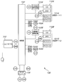
充電台100の回路構成を示す図15をさらに参照すると、図示しない商用電源に接続されるACアダプタ700は、AC100VをDC12Vに変換する。尚、本実施形態において、ACアダプタ700は充電台100に内蔵されているが、ACアダプタ700を充電台100の外部に設けてもよい。
充電台100において、DC/DCコンバータ106は、DC12VをDC3.3Vに変換する。
充電台100は、充電ポート1、2と、充電ポート3に対応するレセプタクルコネクタとを備えている。充電ポート1は、コンタクトピン(台充電端子)101Aを設けた端末搭載部112Aである。充電ポート2は、コンタクトピン(台充電端子)101Bを設けた端末搭載部112Bである。充電ポート3は、レセプタクルコネクタ101Cを介して充電台100に接続された充電ケーブル200、より具体的には、コンタクトピン(ケーブル充電端子)201を設けた端子ハウジング220である。
充電ポート1、2のコンタクトピン101A、101Bはそれぞれ、「12V」、「GND」、「DETECT1」、「DETECT2」端子を含んでいる。充電ポート3に対応したレセプタクルコネクタ101Cもまた、「12V」、「GND」、「DETECT1」、「DETECT2」端子を含んでいる。
コンタクトピン101A、101Bならびにレセプタクルコネクタ101Cにおける「12V」端子と「GND」端子には、充電電圧が供給される。充電台100の制御部102は、充電電圧開閉回路103A、103B、103Cを制御して、12Vの充電電圧をオン/オフする。
コンタクトピン101A、101Bならびにレセプタクルコネクタ101Cにおける「DETECT1」端子と「DETECT2」端子は、携帯端末装置600の検知に用いられる。「DETECT1」端子には3.3Vが供給されている。一方、携帯端末装置600の被充電端子601(図8(c))における「DETECT1」端子と「DETECT2」端子との間は、携帯端末装置600内で導通している。したがって、携帯端末装置600が充電台100の端末搭載部112A、112Bに載置されるか、あるいは、携帯端末装置600に充電ケーブル200の端子ハウジング220が装着されることにより、コンタクトピン101A、101Bあるいはレセプタクルコネクタ101Cにおける「DETECT1」端子の3.3Vが、「DETECT2」端子に出力されることになる。
そして、充電台100の制御部102は、「DETECT2」端子において通常Lowレベルである端子がHighレベル(3.3V)を検出すると、携帯端末装置600を検知したと判断し、充電電圧開閉回路103A、103Bまたは103Cをオンにして充電電圧を供給する。これと共に、LED駆動回路104A、104Bまたは104Cを制御してLED105A、105Bまたは105Cを点灯させる。
制御部102は、「DETECT2」端子においてHighレベル(3.3V)を検出しなくなると、携帯端末装置600を検知しなくなったと判断し、充電電圧開閉回路103A、103Bまたは103Cをオフにして充電電圧を断つ。これと共に、LED駆動回路104A、104Bまたは104Cを制御してLED105A、105Bまたは105Cを滅灯させる。
充電ケーブル200の回路図である図16をさらに参照すると、充電ケーブル200は、そのプラグコネクタ230が充電台100のレセプタクルコネクタ101C(図15)に接続される。プラグコネクタ230には、ケーブル部210を介してコンタクトピン(ケーブル充電端子)201が接続されている。コンタクトピン201を設けた端子ハウジング220は、充電ポート3を構成している。充電ポート3のコンタクトピン201は、「12V」、「GND」、「DETECT1」、「DETECT2」端子を含んでいる。
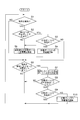
次に、図17をさらに参照して、本充電システムの動作、特に、充電台100の制御部102が実行する処理について説明する。
尚、以下の説明は、充電ポート1~3に共通であるが、充電ポート2については、充電ポート1、3と異なる点がある。これについては、後述する。
図17のステップS1において、充電台100の制御部102は、携帯端末装置600を検知したか否かを判断する。携帯端末装置600を検知した場合(ステップS1のYES)は、ステップS2に移行する。一方、携帯端末装置600を検知していない場合(ステップS1のNO)は、ステップS6に移行する。
ステップS2において、充電台100の制御部102は、携帯端末装置600を検知した充電ポート以外の他の2つの充電ポートで充電中であるか否かを判断する。他の2つの充電ポートで充電中である場合(ステップS2のYES)は、ステップS3に移行する。一方、他の2つの充電ポートで充電中でない場合(ステップS2のNO)は、ステップS5に移行する。
尚、「携帯端末装置600を検知した充電ポート以外の他の2つの充電ポートで充電中である場合」とは、他の2つの充電ポートが共に充電中である場合である。「携帯端末装置600を検知した充電ポート以外の他の2つの充電ポートで充電中でない場合」とは、他の2つの充電ポートが共に充電中でない場合、もしくは、他の2つの充電ポートの内1つが充電中であり、1つが充電中でない場合である。
携帯端末装置600を検知した充電ポート以外の他の2つの充電ポートで充電中であるか/否かを判断する理由は、充電台100に内蔵されたACアダプタ700が、2台分の携帯端末装置の充電電流供給能力しかない、即ち、同時に2台の携帯端末装置しか充電できないためである。
ステップS3において、充電ポート2で充電中であるか否かを判断する。充電ポート2で充電中である場合(ステップS3のYES)は、ステップS4に移行する。一方、充電ポート2で充電中でない場合(ステップS3のNO)は、ステップS6に移行する。
ステップS4において、充電ポート2への充電電圧を断ってステップS5に移行する。即ち、ステップS4においては、充電ポート1、2の両方に携帯端末装置600が載置され、なおかつ、充電ポート3が携帯端末装置600に装着された状態である。即ち、全充電ポート1~3が満杯の状態である。本例においては、2つの充電ポート分の充電能力しかないため、充電ポート1~3のうちの充電ポート2への充電電圧を断って、充電ポート2に載置された携帯端末装置600への充電を止める。
ステップS5において、携帯端末装置600を検知した充電ポートへ充電電圧を供給し、ステップS6に移行する。
ステップS6において、携帯端末装置600を検知しなくなった充電ポートが有るか否かを判断する。携帯端末装置600を検知しなくなった充電ポートが有る場合(ステップS6のYES)は、ステップS7に移行する。一方、携帯端末装置600を検知しなくなった充電ポートがない場合(ステップS6のNO)は、ステップS1に戻る。
ステップS7において、携帯端末装置600を検知しなくなった充電ポートへの充電電圧を断ち、ステップS8に移行する。
ステップS8において、充電ポート2で携帯端末装置600を検知しているか否かを判断する。充電ポート2で携帯端末装置600を検知している場合(ステップS8のYES)は、ステップS9に移行する。一方、充電ポート2で携帯端末装置600を検知していない場合(ステップS8のNO)は、ステップS1に戻る。
ステップS9において、充電ポート2で携帯端末装置600を充電中であるか否かを判断する。充電ポート2で携帯端末装置600を充電中である場合(ステップS9のYES)は、ステップS1に戻る。一方、充電ポート2で携帯端末装置600を充電中でない場合(ステップS9のNO)は、ステップS10に移行する。
ステップS10において、充電ポート2へ充電電圧を供給し、ステップS1に戻る。
以上説明した実施形態1においては、充電台100は、2つの充電ポート1、2、即ち、端末搭載部112A、112Bを有するものとしたが、端末搭載部が1つであってもよい。あるいは、3つ以上の端末搭載部を充電台が有していてもよい。この場合、ACアダプタ700(充電電流供給源)の充電電流供給能力は、端末搭載部の数に対応した台数の携帯端末装置に対して供給可能なものとする。これと共に、(端末搭載部112A、112Bの数+1)の台数の携帯端末装置を検知したとき、充電電圧供給を行わない充電ポート(端末搭載部112A、112Bに対応する充電ポート)を1つ定めておく。
実施形態1の発明によれば、充電台に載置して充電する携帯端末装置であっても、充電を行いながら使用することを可能にする携帯端末装置の充電システムを提供することができる。また、実施形態1の発明によれば、充電台に載置する携帯端末装置の台数分の充電電流供給能力しか持たないACアダプタ(充電電流供給源)で、充電ケーブルにセットされた携帯端末装置の充電を行うことができる。
(実施形態1の変形例)
実施形態1の変形例として、ACアダプタ(充電電流供給源)の充電電流供給能力を、少なくとも、充電ケーブルの充電ポートをも含む全充電ポート数分に供給可能なものとしてもよい。
実施形態1の変形例として、ACアダプタ(充電電流供給源)の充電電流供給能力を、少なくとも、充電ケーブルの充電ポートをも含む全充電ポート数分に供給可能なものとしてもよい。
以下、この変形例による携帯端末装置の充電システムの動作、特に、充電台の制御部が実行する処理について、図15を援用して参照すると共に図18のフローチャートを参照して説明する。
図18のステップS21において、充電台100の制御部102は、携帯端末装置を検知したか否かを判断する。携帯端末装置を検知した場合(ステップS21のYES)は、ステップS22に移行する。一方、携帯端末装置を検知していない場合(ステップS21のNO)は、ステップS23に移行する。
ステップS22において、携帯端末装置を検知した充電ポートへ充電電圧を供給し、ステップS23に移行する。
ステップS23において、携帯端末装置を検知しなくなった充電ポートが有るか否かを判断する。携帯端末装置を検知しなくなった充電ポートが有る場合(ステップS23のYES)は、ステップS24に移行する。一方、携帯端末装置を検知しなくなった充電ポートがない場合(ステップS23のNO)は、ステップS21に戻る。
ステップS24において、携帯端末装置を検知しなくなった充電ポートへの充電電圧を断ち、ステップS21に戻る。
[実施形態2]
本発明の実施形態2は、充電台が充電ポート3と充電ケーブル接続用のレセプタクルコネクタを有していない点、および、充電ケーブルが充電台を介することなく携帯端末装置に充電する点で、実施形態1とは異なる。
本発明の実施形態2は、充電台が充電ポート3と充電ケーブル接続用のレセプタクルコネクタを有していない点、および、充電ケーブルが充電台を介することなく携帯端末装置に充電する点で、実施形態1とは異なる。
実施形態2の場合も、携帯端末装置の被充電端子と充電台のコンタクトピンとの当接と、携帯端末装置の被充電端子と充電ケーブルの端子ハウジングのコンタクトピンとの当接は、実施携帯1と同様に行われる。また、携帯端末装置の被充電端子が、充電台のコンタクトピンと当接する箇所と、充電ケーブルの端子ハウジングのコンタクトピンと当接する箇所とは同一である。
図19および図20を参照すると、本発明の実施形態2による携帯端末装置の充電システムは、充電台100’(図19)と、充電ケーブル(図20)とを有している。
本実施形態の充電台100’は、図6および図15に示した実施形態1の充電台100と異なり、充電ポート3を有していない。即ち、充電ポート3用の、レセプタクルコネクタと、充電電圧開閉回路と、LED駆動回路と、表示部(LED)とを有していない。充電台100’の他の構成は、実施形態1と同様の構成であるため、詳細な説明は省略する。
図19に示すように、充電台100’は、充電ポート1、2を備えている。充電ポート1、2はそれぞれ、実施形態1と同様に、コンタクトピン(台充電端子)101A’、101B’を設けた端末搭載部112A’、112B’である。尚、充電台100’、端末搭載部112A’、112B’、コンタクトピン101A’、101B’の形状や構造については、実施形態1の充電台、端末搭載部、コンタクトピンと同様であるため、図1、図6、図10、図11、図14等を援用して参照することとする。図示しない商用電源に接続されるACアダプタ700’は、AC100VをDC12Vに変換する。DC/DCコンバータ106’は、DC12VをDC3.3Vに変換する。
充電ポート1、2のコンタクトピン101A’、101B’はそれぞれ、「12V」、「GND」、「DETECT1」、「DETECT2」端子を含んでいる。
コンタクトピン101A’、101B’における「12V」端子と「GND」端子には、充電電圧が供給される。充電台100’の制御部102’は、充電電圧開閉回路103A’、103B’を制御して、12Vの充電電圧をオン/オフする。
コンタクトピン101A’、101B’における「DETECT1」端子と「DETECT2」端子は、図7~図9等に示した携帯端末装置600の検知に用いられる。「DETECT1」端子には3.3Vが供給されている。一方、携帯端末装置600の被充電端子601(図8(c))における「DETECT1」端子と「DETECT2」端子との間は、携帯端末装置600内で導通している。したがって、携帯端末装置600が充電台100’の端末搭載部101A’、101B’に載置されることにより、コンタクトピン101A’、101B’における「DETECT1」端子の3.3Vが、「DETECT2」端子に出力されることになる。
そして、充電台100’の制御部102’は、「DETECT2」端子において通常Lowレベルである端子がHighレベル(3.3V)を検出すると、携帯端末装置600を検知したと判断し、充電電圧開閉回路103A’、103B’をオンにして充電電圧を供給する。これと共に、LED駆動回路104A’、104B’を制御してLED105A’、105B’を点灯させる。
制御部102’は、「DETECT2」端子においてHighレベル(3.3V)を検出しなくなると、携帯端末装置600を検知しなくなったと判断し、充電電圧開閉回路103A’、103B’をオフにして充電電圧を断つ。これと共に、LED駆動回路104A’、104B’を制御してLED105A’、105B’を滅灯させる。
次に、本発明の実施形態2における充電台100’の動作、特に、その制御部102’が実行する処理について、図19を参照すると共に、図18(実施形態1の変形例のフローチャート)を援用して参照して説明する。
図18のステップS21において、充電台100’の制御部102’は、携帯端末装置を検知したか否かを判断する。携帯端末装置を検知した場合(ステップS21のYES)は、ステップS22に移行する。一方、携帯端末装置を検知していない場合(ステップS21のNO)は、ステップS23に移行する。
ステップS22において、携帯端末装置を検知した充電ポートへ充電電圧を供給し、ステップS23に移行する。
ステップS23において、携帯端末装置を検知しなくなった充電ポートが有るか否かを判断する。携帯端末装置を検知しなくなった充電ポートが有る場合(ステップS23のYES)は、ステップS24に移行する。一方、携帯端末装置を検知しなくなった充電ポートがない場合(ステップS23のNO)は、ステップS21に戻る。
ステップS24において、携帯端末装置を検知しなくなった充電ポートへの充電電圧を断ち、ステップS21に戻る。
図20は、本実施形態の充電ケーブル200’の回路構成を示す図である。ACアダプタ800は、AC100VをDC12Vに変換する。DC/DCコンバータ206は、DC12VをDC3.3Vに変換する。
図20に示すように、充電ケーブル200’は、単一の充電ポート3’を備えている。
充電ポート3’は、コンタクトピン(ケーブル充電端子)201’を設けた端子ハウジング220’である。端子ハウジング220’、コンタクトピン201’の形状や構造については、実施形態1の端子ハウジング、コンタクトピンと同様であるため、図1~図5、図12~図14等を援用して参照することとする。
端子ハウジング220’の内部には、実施形態1と同様に、吸着部として磁石が取り付けられている。
充電ポート3’は、「12V」、「GND」、「DETECT1」、「DETECT2」端子を含んでいる。
コンタクトピン201’における「12V」端子と「GND」端子には、充電電圧が供給される。充電ケーブル200’の制御部202は、充電電圧開閉回路203を制御して、12Vの充電電圧をオン/オフする。
コンタクトピン201’における「DETECT1」端子と「DETECT2」端子は、図7~図9等に示した携帯端末装置600の検知に用いられる。「DETECT1」端子には3.3Vが供給されている。一方、携帯端末装置600の被充電端子601(図8(c))における「DETECT1」端子と「DETECT2」端子との間は、携帯端末装置600内で導通している。したがって、携帯端末装置600に充電ケーブル200’の端子ハウジング220’が装着されることにより、コンタクトピン201’における「DETECT1」端子の3.3Vが、「DETECT2」端子に出力されることになる。
そして、充電ケーブル200’の制御部202は、「DETECT2」端子において通常Lowレベルである端子がHighレベル(3.3V)を検出すると、携帯端末装置600を検知したと判断し、充電電圧開閉回路203をオンにして充電電圧を供給する。これと共に、LED駆動回路204を制御してLED205を点灯させる。
制御部制御部202は、「DETECT2」端子においてHighレベル(3.3V)を検出しなくなると、携帯端末装置600を検知しなくなったと判断し、充電電圧開閉回路203をオフにして充電電圧を断つ。これと共に、LED駆動回路204を制御してLED205を滅灯させる。
次に、本発明の実施形態2における充電ケーブル200’の動作、特に、その制御部202が実行する処理について、図20および図21を参照して説明する。
図21のステップS31において、充電ケーブル200’の制御部202は、充電ポート3’に携帯端末装置を検知したか否かを判断する。携帯端末装置を検知した場合(ステップS31のYES)は、ステップS32に移行する。一方、携帯端末装置を検知していない場合(ステップS31のNO)は、ステップS33に移行する。
ステップS32において、携帯端末装置を検知した充電ポート3’へ充電電圧を供給し、ステップS33に移行する。
ステップS33において、充電ポート3’において携帯端末装置を検知しなくなったか否かを判断する。携帯端末装置を検知しなくなった場合(ステップS33のYES)は、ステップS34に移行する。一方、携帯端末装置を検知している場合(ステップS33のNO)は、ステップS31に戻る。
ステップS34において、携帯端末装置を検知しなくなった充電ポート3’への充電電圧を断ち、ステップS31に戻る。
尚、実施形態2において、充電台100’は、2つの端末搭載部112A’、112B’を有するものとしたが、端末搭載部が1つであってもよいし、3つ以上であってもよい。
実施形態2の発明によれば、充電台に載置して充電する携帯端末装置であっても、充電を行いながら使用することを可能にする携帯端末装置の充電システムを提供することができる。
本発明は、以上説明した実施形態には限定されない。
例えば、実施形態1、実施形態1の変形例、実施形態2では、携帯端末装置に被吸着部として金属板が設けられている一方、充電ケーブルの端子ハウジングに吸着部としての磁石を設けたが、携帯端末装置に被吸着部として磁石を設けられている一方、充電ケーブルの端子ハウジングに吸着部としての金属板を設けてもよい。あるいは、携帯端末装置に被吸着部として磁石が設けられている一方、充電ケーブルの端子ハウジングにも、吸着部としての磁石を設けてもよい。この場合、磁石同士が引き合う磁力が発生するような磁極配置とする。即ち、携帯端末装置の磁石のN極と端子ハウジングの磁石のS極とが対向するように、あるいは、携帯端末装置の磁石のS極と端子ハウジングの磁石のN極とが対向するように配置する。
また、上記実施形態1、実施形態1の変形例、実施形態2においては、台充電端子およびケーブル充電端子をコンタクトピンとしたが、台充電端子および/またはケーブル充電端子を板バネ状の端子としてもよい。
この出願は、2015年11月24日に出願された日本出願特願第2015-228588号を基礎とする優先権を主張し、その開示の全てをここに取り込む。
100、100’ 充電台
101A、101B、101A’、101B’ コンタクトピン(台充電端子)
101C レセプタクルコネクタ
102、102’ 制御部
103A、103B、103C、103A’、103B’ 充電電圧開閉回路
104A、104B、104C、104A’、104B’ LED駆動回路
105A、105B、105C、105A’、105B’ 表示部(LED)
106、106’ DC/DCコンバータ
112A、112B、112A’、112B’ 端末搭載部
114A、114B ガイド凸部
115A、115B ガイド端部
200、200’ 充電ケーブル
201、201’ コンタクトピン(ケーブル充電端子)
202 制御部
203 充電電圧開閉回路
204 LED駆動回路
205 表示部(LED)
206 DC/DCコンバータ
210 ケーブル部
220、220’ 端子ハウジング
221a 基部
221b 立設部
221c 背面カバー
221d 底面カバー
222 当接面
223 リブ
224 ガイド凸部
225 係止凸部
226 磁石
230 プラグコネクタ
600 携帯端末装置
600r リアパネル
600td タッチパネル付きディスプレイ
601 被充電端子
604 端子隣接凹部
605 背面凹部
606 金属板
700、700’、800 ACアダプタ
101A、101B、101A’、101B’ コンタクトピン(台充電端子)
101C レセプタクルコネクタ
102、102’ 制御部
103A、103B、103C、103A’、103B’ 充電電圧開閉回路
104A、104B、104C、104A’、104B’ LED駆動回路
105A、105B、105C、105A’、105B’ 表示部(LED)
106、106’ DC/DCコンバータ
112A、112B、112A’、112B’ 端末搭載部
114A、114B ガイド凸部
115A、115B ガイド端部
200、200’ 充電ケーブル
201、201’ コンタクトピン(ケーブル充電端子)
202 制御部
203 充電電圧開閉回路
204 LED駆動回路
205 表示部(LED)
206 DC/DCコンバータ
210 ケーブル部
220、220’ 端子ハウジング
221a 基部
221b 立設部
221c 背面カバー
221d 底面カバー
222 当接面
223 リブ
224 ガイド凸部
225 係止凸部
226 磁石
230 プラグコネクタ
600 携帯端末装置
600r リアパネル
600td タッチパネル付きディスプレイ
601 被充電端子
604 端子隣接凹部
605 背面凹部
606 金属板
700、700’、800 ACアダプタ
Claims (10)
- 携帯端末装置を取り出し可能に搭載する充電台と、携帯端末装置に取り外し可能に装着される充電ケーブルとを有し、
前記充電台は、携帯端末装置を搭載する端末搭載部と、該端末搭載部に搭載された携帯端末装置の被充電端子に当接して携帯端末装置に充電を行う台充電端子を備え、
前記充電ケーブルは、装着された携帯端末装置の被充電端子に当接して携帯端末装置に充電を行うケーブル充電端子を備えていることを特徴とする携帯端末装置の充電システム。 - 前記ケーブル充電端子の配置及び配列と、前記台充電端子の配置及び配列とは、同一であることを特徴とする請求項1に記載の携帯端末装置の充電システム。
- 前記ケーブル充電端子と前記台充電端子とは、それぞれ原位置に復帰可能な弾性を伴って可動するものであり、かつ、それぞれの可動範囲が等しいことを特徴とする請求項2に記載の携帯端末装置の充電システム。
- 前記充電ケーブルは、前記ケーブル充電端子が設けられ、携帯端末装置に取り外し可能に装着される端子ハウジングをさらに備え、
前記端子ハウジングは、携帯端末装置に装着されたときに装着状態を維持すべく、携帯端末装置に備えられた被吸着部に対して吸着する吸着部を備え、
前記吸着部は、携帯端末装置の被吸着部が金属板から成る場合は、磁石から成り、携帯端末装置の被吸着部が磁石から成る場合は、金属板または磁石から成ることを特徴とする請求項1乃至3のいずれか一項に記載の携帯端末装置の充電システム。 - 前記充電ケーブルは、前記充電台に取り外し可能に接続され、前記充電台を介して前記ケーブル充電端子に電源供給することにより、携帯端末装置に充電を行うことを特徴とする請求項1乃至4のいずれか一項に記載の携帯端末装置の充電システム。
- 前記充電台は、前記充電ケーブルが接続されたときに、前記台充電端子への電源供給を断つことを特徴とする請求項5に記載の携帯端末装置の充電システム。
- 前記充電台は、前記端末搭載部および前記台充電端子をそれぞれ複数備えることを特徴とする請求項1乃至6のいずれか一項に記載の携帯端末装置の充電システム。
- 携帯端末装置に取り外し可能に装着され、
装着された携帯端末装置の被充電端子に当接して携帯端末装置に充電を行うケーブル充電端子と、
前記ケーブル充電端子が設けられ、携帯端末装置に取り外し可能に装着される端子ハウジングとを備え、
前記端子ハウジングは、携帯端末装置に装着されたときに装着状態を維持すべく、携帯端末装置に備えられた被吸着部に対して吸着する吸着部を備え、
前記吸着部は、携帯端末装置の被吸着部が金属板から成る場合は、磁石から成り、携帯端末装置の被吸着部が磁石から成る場合は、金属板または磁石から成ることを特徴とする携帯端末装置の充電ケーブル。 - 携帯端末装置は、携帯端末装置を取り出し可能に搭載し、携帯端末装置に充電を行う充電台によっても充電可能であり、
充電台は、携帯端末装置の被充電端子に当接して携帯端末装置に充電を行う台充電端子を備え、
前記ケーブル充電端子の配置及び配列は、充電台の台充電端子の配置及び配列と同一であることを特徴とする請求項8に記載の携帯端末装置の充電ケーブル。 - 前記ケーブル充電端子と前記台充電端子とは、それぞれ原位置に復帰可能な弾性を伴って可動するものであり、かつ、それぞれの可動範囲が等しいことを特徴とする請求項9に記載の携帯端末装置の充電ケーブル。
Priority Applications (2)
| Application Number | Priority Date | Filing Date | Title |
|---|---|---|---|
| US15/777,283 US10615620B2 (en) | 2015-11-24 | 2016-08-26 | Charging system and charging cable for portable terminal device |
| CN201680068216.9A CN108292852B (zh) | 2015-11-24 | 2016-08-26 | 便携式终端装置的充电系统和充电电缆 |
Applications Claiming Priority (2)
| Application Number | Priority Date | Filing Date | Title |
|---|---|---|---|
| JP2015228588A JP2017099126A (ja) | 2015-11-24 | 2015-11-24 | 携帯端末装置の充電システムおよび充電ケーブル |
| JP2015-228588 | 2015-11-24 |
Publications (1)
| Publication Number | Publication Date |
|---|---|
| WO2017090217A1 true WO2017090217A1 (ja) | 2017-06-01 |
Family
ID=58763256
Family Applications (1)
| Application Number | Title | Priority Date | Filing Date |
|---|---|---|---|
| PCT/JP2016/003891 Ceased WO2017090217A1 (ja) | 2015-11-24 | 2016-08-26 | 携帯端末装置の充電システムおよび充電ケーブル |
Country Status (4)
| Country | Link |
|---|---|
| US (1) | US10615620B2 (ja) |
| JP (1) | JP2017099126A (ja) |
| CN (1) | CN108292852B (ja) |
| WO (1) | WO2017090217A1 (ja) |
Citations (7)
| Publication number | Priority date | Publication date | Assignee | Title |
|---|---|---|---|---|
| JPH0833214A (ja) * | 1994-07-13 | 1996-02-02 | Sanyo Electric Co Ltd | 充電器 |
| JPH11178229A (ja) * | 1997-12-16 | 1999-07-02 | Nec Corp | 充電装置 |
| JP2000324220A (ja) * | 1999-05-07 | 2000-11-24 | Mitsubishi Electric Corp | 携帯無線電話機の保持機構 |
| JP2006246217A (ja) * | 2005-03-04 | 2006-09-14 | Pentax Corp | 携帯端末システム |
| JP2010063117A (ja) * | 2009-10-19 | 2010-03-18 | Kyocera Corp | 通信機ユニット |
| US20130076136A1 (en) * | 2006-12-20 | 2013-03-28 | Techtium Ltd. | Battery Powered Charger |
| JP2013110915A (ja) * | 2011-11-24 | 2013-06-06 | Nec Saitama Ltd | 充電器、充電制御方法およびプログラム |
Family Cites Families (14)
| Publication number | Priority date | Publication date | Assignee | Title |
|---|---|---|---|---|
| JPS52103332U (ja) * | 1976-02-03 | 1977-08-05 | ||
| JPH0542625Y2 (ja) * | 1988-09-07 | 1993-10-27 | ||
| JP3057172B2 (ja) * | 1990-11-21 | 2000-06-26 | 東洋通信機株式会社 | 電子機器の接続孔の静電気侵入防止構造 |
| JP2605537B2 (ja) * | 1991-12-16 | 1997-04-30 | 松下電器産業株式会社 | 充電装置 |
| JPH0591153U (ja) * | 1992-05-18 | 1993-12-10 | 株式会社東芝 | 電子機器と充電器との接続構造 |
| JP3420312B2 (ja) * | 1993-12-27 | 2003-06-23 | 京セラ株式会社 | 電源端子板圧接構造 |
| JP2002354094A (ja) | 2001-05-24 | 2002-12-06 | Matsushita Electric Ind Co Ltd | 無線電話機用充電台 |
| US8675356B2 (en) * | 2007-02-20 | 2014-03-18 | Jack Strauser | System and, method for holding and powering three consumer electronic devices |
| JP5328341B2 (ja) * | 2008-12-27 | 2013-10-30 | 三洋電機株式会社 | 携帯機器の充電台 |
| JP5234176B2 (ja) | 2009-04-23 | 2013-07-10 | トヨタ自動車株式会社 | 車両、充電ケーブルおよび車両の充電システム |
| JP5204884B2 (ja) | 2011-10-27 | 2013-06-05 | Necインフロンティア株式会社 | 充電台 |
| KR101924902B1 (ko) * | 2012-10-22 | 2018-12-04 | 삼성전자주식회사 | 휴대용 단말기의 접속 장치 |
| CN203326633U (zh) * | 2013-05-22 | 2013-12-04 | 富港电子(东莞)有限公司 | 充电座及其电连接器组合 |
| CN203933098U (zh) * | 2014-05-29 | 2014-11-05 | 陈世崇 | 组合式移动电源 |
-
2015
- 2015-11-24 JP JP2015228588A patent/JP2017099126A/ja active Pending
-
2016
- 2016-08-26 CN CN201680068216.9A patent/CN108292852B/zh not_active Expired - Fee Related
- 2016-08-26 US US15/777,283 patent/US10615620B2/en active Active
- 2016-08-26 WO PCT/JP2016/003891 patent/WO2017090217A1/ja not_active Ceased
Patent Citations (7)
| Publication number | Priority date | Publication date | Assignee | Title |
|---|---|---|---|---|
| JPH0833214A (ja) * | 1994-07-13 | 1996-02-02 | Sanyo Electric Co Ltd | 充電器 |
| JPH11178229A (ja) * | 1997-12-16 | 1999-07-02 | Nec Corp | 充電装置 |
| JP2000324220A (ja) * | 1999-05-07 | 2000-11-24 | Mitsubishi Electric Corp | 携帯無線電話機の保持機構 |
| JP2006246217A (ja) * | 2005-03-04 | 2006-09-14 | Pentax Corp | 携帯端末システム |
| US20130076136A1 (en) * | 2006-12-20 | 2013-03-28 | Techtium Ltd. | Battery Powered Charger |
| JP2010063117A (ja) * | 2009-10-19 | 2010-03-18 | Kyocera Corp | 通信機ユニット |
| JP2013110915A (ja) * | 2011-11-24 | 2013-06-06 | Nec Saitama Ltd | 充電器、充電制御方法およびプログラム |
Also Published As
| Publication number | Publication date |
|---|---|
| US10615620B2 (en) | 2020-04-07 |
| CN108292852A (zh) | 2018-07-17 |
| JP2017099126A (ja) | 2017-06-01 |
| CN108292852B (zh) | 2021-02-05 |
| US20180331549A1 (en) | 2018-11-15 |
Similar Documents
| Publication | Publication Date | Title |
|---|---|---|
| CN105958558B (zh) | 蓄电池收纳装置 | |
| US20220399748A1 (en) | Power system for mobile workstation | |
| US8072183B2 (en) | Multiple interface device charger with removable battery pack | |
| TWI581088B (zh) | 移動電源 | |
| CN105391105B (zh) | 充电式电气设备 | |
| KR20130132809A (ko) | 휴대용 전자 장치들을 위한 케이스들 | |
| US20110127955A1 (en) | Wireless rechargeable battery | |
| EP3406017A1 (en) | Portable power bank for a smartwatch or the like | |
| JP6381060B2 (ja) | 携帯端末装置の充電システム | |
| JP6292389B2 (ja) | 照明装置 | |
| JP6238391B2 (ja) | 携帯端末装置の充電システム | |
| KR20140062837A (ko) | 휴대형 무선 전력 전송 장치 및 휴대형 무선 전력 전송 장치용 거치형 도킹 스테이션 | |
| JP2017099126A (ja) | 携帯端末装置の充電システムおよび充電ケーブル | |
| JP7197831B2 (ja) | 照明装置 | |
| US10886768B2 (en) | Seeing aid device having inductive battery charging | |
| JP3207668U (ja) | 卓上充電スタンド | |
| KR20210008619A (ko) | 전자담배용 커버 | |
| JP3204992U (ja) | 充電保護ケース | |
| KR20170000026U (ko) | 보조 배터리 겸용 충전기 | |
| KR20160089120A (ko) | 착탈식 배터리 및 이와 연결되는 전자 기기 | |
| JP7003576B2 (ja) | 照明器具 | |
| KR101695635B1 (ko) | 휴대용 살균기 및 자가발전에 의한 휴대용 조작기 | |
| JP3175908U (ja) | 照明装置用のダミー口金 | |
| CN113154279A (zh) | 用于电器的照明电源的连接装置、连接组件以及冰箱 | |
| CN105337337A (zh) | 手机充电装置及其手机套 |
Legal Events
| Date | Code | Title | Description |
|---|---|---|---|
| 121 | Ep: the epo has been informed by wipo that ep was designated in this application |
Ref document number: 16868168 Country of ref document: EP Kind code of ref document: A1 |
|
| WWE | Wipo information: entry into national phase |
Ref document number: 15777283 Country of ref document: US |
|
| NENP | Non-entry into the national phase |
Ref country code: DE |
|
| 122 | Ep: pct application non-entry in european phase |
Ref document number: 16868168 Country of ref document: EP Kind code of ref document: A1 |