WO2017073587A1 - 燃料ポンプ用インペラ - Google Patents
燃料ポンプ用インペラ Download PDFInfo
- Publication number
- WO2017073587A1 WO2017073587A1 PCT/JP2016/081659 JP2016081659W WO2017073587A1 WO 2017073587 A1 WO2017073587 A1 WO 2017073587A1 JP 2016081659 W JP2016081659 W JP 2016081659W WO 2017073587 A1 WO2017073587 A1 WO 2017073587A1
- Authority
- WO
- WIPO (PCT)
- Prior art keywords
- mass
- impeller
- parts
- fuel pump
- inorganic filler
- Prior art date
- Legal status (The legal status is an assumption and is not a legal conclusion. Google has not performed a legal analysis and makes no representation as to the accuracy of the status listed.)
- Ceased
Links
Images

Classifications
-
- F—MECHANICAL ENGINEERING; LIGHTING; HEATING; WEAPONS; BLASTING
- F02—COMBUSTION ENGINES; HOT-GAS OR COMBUSTION-PRODUCT ENGINE PLANTS
- F02M—SUPPLYING COMBUSTION ENGINES IN GENERAL WITH COMBUSTIBLE MIXTURES OR CONSTITUENTS THEREOF
- F02M37/00—Apparatus or systems for feeding liquid fuel from storage containers to carburettors or fuel-injection apparatus; Arrangements for purifying liquid fuel specially adapted for, or arranged on, internal-combustion engines
- F02M37/04—Feeding by means of driven pumps
- F02M37/08—Feeding by means of driven pumps electrically driven
- F02M37/10—Feeding by means of driven pumps electrically driven submerged in fuel, e.g. in reservoir
-
- C—CHEMISTRY; METALLURGY
- C08—ORGANIC MACROMOLECULAR COMPOUNDS; THEIR PREPARATION OR CHEMICAL WORKING-UP; COMPOSITIONS BASED THEREON
- C08K—Use of inorganic or non-macromolecular organic substances as compounding ingredients
- C08K3/00—Use of inorganic substances as compounding ingredients
- C08K3/34—Silicon-containing compounds
- C08K3/346—Clay
-
- C—CHEMISTRY; METALLURGY
- C08—ORGANIC MACROMOLECULAR COMPOUNDS; THEIR PREPARATION OR CHEMICAL WORKING-UP; COMPOSITIONS BASED THEREON
- C08K—Use of inorganic or non-macromolecular organic substances as compounding ingredients
- C08K3/00—Use of inorganic substances as compounding ingredients
- C08K3/34—Silicon-containing compounds
- C08K3/36—Silica
-
- C—CHEMISTRY; METALLURGY
- C08—ORGANIC MACROMOLECULAR COMPOUNDS; THEIR PREPARATION OR CHEMICAL WORKING-UP; COMPOSITIONS BASED THEREON
- C08K—Use of inorganic or non-macromolecular organic substances as compounding ingredients
- C08K5/00—Use of organic ingredients
- C08K5/16—Nitrogen-containing compounds
- C08K5/34—Heterocyclic compounds having nitrogen in the ring
- C08K5/3467—Heterocyclic compounds having nitrogen in the ring having more than two nitrogen atoms in the ring
- C08K5/3477—Six-membered rings
-
- C—CHEMISTRY; METALLURGY
- C08—ORGANIC MACROMOLECULAR COMPOUNDS; THEIR PREPARATION OR CHEMICAL WORKING-UP; COMPOSITIONS BASED THEREON
- C08K—Use of inorganic or non-macromolecular organic substances as compounding ingredients
- C08K7/00—Use of ingredients characterised by shape
- C08K7/02—Fibres or whiskers
- C08K7/04—Fibres or whiskers inorganic
- C08K7/14—Glass
-
- C—CHEMISTRY; METALLURGY
- C08—ORGANIC MACROMOLECULAR COMPOUNDS; THEIR PREPARATION OR CHEMICAL WORKING-UP; COMPOSITIONS BASED THEREON
- C08L—COMPOSITIONS OF MACROMOLECULAR COMPOUNDS
- C08L61/00—Compositions of condensation polymers of aldehydes or ketones; Compositions of derivatives of such polymers
- C08L61/04—Condensation polymers of aldehydes or ketones with phenols only
- C08L61/06—Condensation polymers of aldehydes or ketones with phenols only of aldehydes with phenols
-
- F—MECHANICAL ENGINEERING; LIGHTING; HEATING; WEAPONS; BLASTING
- F04—POSITIVE - DISPLACEMENT MACHINES FOR LIQUIDS; PUMPS FOR LIQUIDS OR ELASTIC FLUIDS
- F04D—NON-POSITIVE-DISPLACEMENT PUMPS
- F04D29/00—Details, component parts, or accessories
- F04D29/02—Selection of particular materials
-
- F—MECHANICAL ENGINEERING; LIGHTING; HEATING; WEAPONS; BLASTING
- F04—POSITIVE - DISPLACEMENT MACHINES FOR LIQUIDS; PUMPS FOR LIQUIDS OR ELASTIC FLUIDS
- F04D—NON-POSITIVE-DISPLACEMENT PUMPS
- F04D5/00—Pumps with circumferential or transverse flow
Definitions
- This disclosure relates to a fuel pump impeller.
- a fuel pump used for a vehicle or the like has a housing that forms a pump chamber into which fuel flows and a resin impeller provided inside the housing.
- a predetermined clearance is secured between the inner wall of the housing and the impeller. This clearance is set to such a magnitude that the impeller does not stop rotating due to contact between the impeller and the housing even when the impeller is swollen by the fuel and water contained in the fuel.
- the clearance between the impeller and the housing is large, there is a problem that output loss increases due to fuel leakage from the clearance or power consumption increases.
- the impeller for a fuel pump described in Patent Document 1 is formed from a resin material including a phenol aralkyl resin, a phenol resin, and glass fiber.
- SP value solubility parameter
- the molding material for molding the impeller described in Patent Document 1 uses a modified phenolic resin and therefore has few molecular crosslinking points.
- the impeller of patent document 1 has high water resistance, there exists a possibility that a crosslinking density may become coarse and the swelling amount by a fuel may become large. Further, even when the interfacial adhesive force between the resin and the glass fiber is small, there is a risk that the amount of swelling due to fuel and water increases.
- PPS polyphenylene sulfide
- the resin has a smaller swelling amount with respect to the fuel and water than the PPS resin. Development of materials is required.
- the present disclosure has been made in view of the above problems, and an object of the present disclosure is to provide a fuel pump impeller with a small amount of swelling with respect to fuel and water.
- the fuel pump impeller according to the present disclosure includes a phenol resin and an inorganic filler.
- the free induction decay curve obtained by the solid echo method in pulse NMR measurement at 90 ° C. is approximated by the sum of the relaxation curves of the three components, the component amount with the shortest spin-spin relaxation time is 70% or more of the total.
- the amount of the component having the shortest spin-spin relaxation time corresponds to the amount of the component crosslinked with the phenol resin constituting the fuel pump impeller.
- the inventors of the present disclosure have focused on the fact that the amount of swelling with respect to a liquid containing fuel and water decreases as the crosslinking density of the phenol resin increases.
- an impeller having a minimum spin-spin relaxation time of 70% or more has a smaller swelling amount (%) with respect to a liquid containing fuel and water than a swelling amount (%) of an impeller molded with PPS resin. It has been found.
- an impeller for a fuel pump that has a smaller swelling amount with respect to fuel and water than an impeller molded with PPS resin.
- a fuel pump in which an impeller according to an embodiment is used.
- the top view of the impeller for fuel pumps which concerns on one Embodiment.
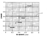
- the graph which shows the relationship between the component amount of the minimum relaxation time, and the swelling amount of the impeller immersed in the fuel.
- the graph which shows the relationship between the minimum relaxation time and the swelling amount of the impeller immersed in the fuel.
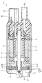
- FIG. 1 shows a fuel pump 2 in which an impeller 1 for a fuel pump according to an embodiment of the present disclosure is used.
- the fuel pump 2 is provided, for example, in a fuel tank of a vehicle.
- the configuration of the fuel pump 2 will be described.
- the fuel pump 2 includes a motor unit 3 and a pump unit 4.
- the motor unit 3 and the pump unit 4 are integrally configured by a cylindrical pump case 5.
- the motor unit 3 includes a stator 7 around which a coil 6 is wound, a rotor 8 that is rotatably provided inside the stator 7, and a shaft 9 that rotates together with the rotor 8.
- the stator 7 When power is supplied from the terminal 101 of the connector 10 to the coil 6 of the stator 7, the stator 7 generates a rotating magnetic field.
- the rotor 8 magnetized alternately with N and S poles in the circumferential direction rotates around the axis together with the shaft 9.
- the pump unit 4 includes an impeller 1, a first pump housing 11, and a second pump housing 12.
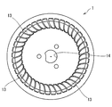
- the impeller 1 is formed from a resin in a substantially disk shape, and has a plurality of blade grooves 13 provided side by side in the circumferential direction.
- the shaft 9 of the motor unit 3 is fitted in the central hole 14 of the impeller 1. Therefore, the impeller 1 rotates with the shaft 9.
- the shape of the impeller is not limited to that shown in FIGS. 1 and 2 and can be various shapes.
- the impeller 1 is accommodated in a pump chamber 15 formed between the first pump housing 11 and the second pump housing 12.
- the first pump housing 11 and the second pump housing 12 are made of a metal such as aluminum, for example.
- the first pump housing 11 has a suction port 16. Moreover, the 1st pump housing 11 has the 1st groove
- the second pump housing 12 has a communication port 18 communicating with the motor unit 3 side. Moreover, the 2nd pump housing 12 has the 2nd groove
- the fuel discharged from the pump unit 4 to the motor unit 3 flows through the gap between the housing and the stator 7 and the gap between the stator 7 and the rotor 8 and is discharged from the discharge port 20 of the fuel pump 2 to the internal combustion engine.
- a predetermined clearance ⁇ is secured between the inner wall of the pump chamber 15 formed between the first pump housing 11 and the second pump housing 12 and the impeller 1 of the present embodiment.
- the clearance ⁇ between the impeller 1 and the housing is large, output loss may increase due to fuel leakage from the clearance, or power consumption may increase.
- PPS resin may be employed as a resin material for forming a fuel pump impeller.
- this PPS resin Solvay R7-120NA
- the impeller of this embodiment has a smaller amount of swelling with respect to the liquid than an impeller molded with PPS resin.
- the content of the phenolic resin including novolac-type phenolic resin and hexamethylenetetramine as a whole impeller is 20 to 55% by mass, and the content of the inorganic filler is 45 to 80% by mass. It is preferable. It is more preferable that the content of the phenol resin is 20 to 30% by mass and the content of the inorganic filler is 70 to 80% by mass.
- the impeller When the impeller is molded from a resin molding material, the fluidity deteriorates by injection molding by setting the content of the phenolic resin to 20% by mass or more and the content of the inorganic filler to 80% by mass or less as the entire impeller. Therefore, productivity can be increased. Furthermore, since the impeller is prevented from being easily broken, workability such as assembly of the impeller can be improved.
- the above-mentioned phenol resin contains a novolac type phenol resin and hexamethylenetetramine.
- the content of hexamethylenetetramine in the phenol resin is preferably 17 to 26 parts by mass, more preferably 20 to 25 parts by mass with respect to 100 parts by mass of the novolac type phenol resin.
- hexamethylenetetramine By setting the content of hexamethylenetetramine to 26 parts by mass or less with respect to 100 parts by mass of the novolak-type phenol resin, it is possible to suppress surplus hexamethylenetetramine from remaining in the resin part of the molding material. Therefore, since the generation of basic gas of hexamethylenetetramine is suppressed during injection molding of resin molding materials and after baking after injection molding, problems such as swelling and cracking of the impeller that is the molded product are suppressed. Can be prevented.
- the above-mentioned novolac type phenol resin contains 100 to 90 parts by mass of an unmodified novolac type phenol resin having a molecular structure represented by the following chemical formula (1) with respect to 100 parts by mass of the novolac type phenol resin. Is preferred.
- chemical formula (1) n is 1 or an integer of 2 or more.
- the unmodified novolac type phenolic resin has more reactive points for crosslinking as compared with the modified phenolic resin. Therefore, it is preferable that the content of the modified phenol resin is 0 to 10 parts by mass and the content of the unmodified novolac phenol resin is 100 to 90 parts by mass with respect to 100 parts by mass of the novolac type phenol resin. More preferably, the content of the modified phenolic resin is 0 to 5 parts by mass, and the content of the unmodified novolac type phenolic resin is 100 to 95 parts by mass.
- the crosslinking density of the phenol resin can be increased by the reaction of the unmodified novolak-type phenol resin and hexamethylenetetramine. Accordingly, the swelling amount of the phenol resin with respect to the fuel and water can be reduced.
- the glass fiber content is preferably 50 to 65 parts by mass, more preferably 53 to 63 parts by mass with respect to 100 parts by mass of the inorganic filler.
- the glass fiber content is preferably 50 to 65 parts by mass, more preferably 53 to 63 parts by mass with respect to 100 parts by mass of the inorganic filler.
- the content of the glass fiber is 65 parts by mass or less, when the impeller is injection-molded from the resin molding material, it is possible to prevent the fluidity from being deteriorated and difficult to mold, and to increase the productivity.
- the clay content in the inorganic filler is preferably 25 to 35 parts by mass, more preferably 30 to 34 parts by mass with respect to 100 parts by mass of the inorganic filler.
- Clay is familiar to the phenol resin and can penetrate into the phenol resin finely to suppress swelling. Therefore, by setting the clay content to 25 parts by mass or more, the amount of impeller swelling with respect to fuel and water can be reduced.
- the clay content By setting the clay content to 35 parts by mass or less, when the impeller is injection-molded from the resin molding material, it is possible to prevent fluidity from being deteriorated and difficult to mold, and increase productivity. In addition, the mechanical strength of the impeller can be prevented from decreasing.
- the silica content in the inorganic filler is preferably 5 to 15 parts by mass, more preferably 7 to 13 parts by mass with respect to 100 parts by mass of the inorganic filler.
- the inorganic filler described above is preferably composed of only a silicon compound without containing, for example, calcium carbonate. Since the silicon compound has high reactivity with the silane coupling agent, it is possible to enhance the interfacial adhesion between the inorganic filler and the phenol resin. Therefore, a fuel pump impeller with a small amount of swelling with respect to fuel and water can be obtained.
- the silicon compound includes silicon in the composition. In this embodiment, for example, silica, clay, talc, mica, glass beads, glass flakes, wollastonite, and the like are used as the silicon compound.
- the impeller described above can appropriately use various fillers and various additives used in ordinary thermosetting resin molding materials.
- a mold release agent such as stearic acid or zinc stearate, an adhesion improver or coupling agent for improving the adhesion between the filler and the thermosetting resin, a color pigment or color dye such as carbon black, a solvent Etc.
- a mold release agent such as stearic acid or zinc stearate
- an adhesion improver or coupling agent for improving the adhesion between the filler and the thermosetting resin a color pigment or color dye such as carbon black, a solvent Etc.
- the molding material for forming the impeller described above is manufactured by a normal method. For example, after blending the above-mentioned various raw materials and mixing uniformly, kneading apparatus such as rolls, kneaders, twin screw extruders alone or in combination with a roll and other mixing apparatus, and then granulating or grinding. Obtained.
- This molding material is suitable for injection molding, but the molding method is not particularly limited to injection molding, and can be molded by any other method such as transfer molding, compression molding, injection compression molding.
- the impeller is formed by injection molding or the like, it is preferable to perform after baking in which the impeller is heated for a predetermined time under a predetermined temperature. Thereby, it is possible to further increase the crosslinking density of the phenol resin.
- Both the after-baking of the molding material and the after-baking of the impeller which is the molded product are preferably carried out at 160 to 180 ° C. for 50 to 70 minutes, more preferably at 165 to 175 ° C. for 55 to 65 minutes.
- the material mixture blended with the composition shown in Table 1 and Table 2 was kneaded with heating rolls having different rotational speeds, and the one cooled in a sheet shape was pulverized to obtain a soot-like molding material.
- the molding material used in the examples includes the following blends. (1) Novolac type phenol resin (2) Xylene-modified novolac type phenol resin (3) Hexamethylenetetramine (4) Glass fiber (5) Clay (6) Silica (7) Calcium carbonate (8) Silane coupling agent
- test piece molding method and evaluation method used for property evaluation are as follows.
- a bending test piece (length: 80 mm, width: 10 mm, thickness: 4 mm) is prepared by compression molding (mold temperature: 175 ° C., curing time: 180 seconds), and the length direction is cut out from the central portion in a width of 2 mm, 10 mm, 4 mm, 2 mm. I got a rectangular parallelepiped. After baking of the test piece was performed at 170 ° C. for 1 hour.
- the impeller shape of FIG. 2 was produced by transfer molding (mold temperature: 175 ° C., curing time: 20 seconds). After baking of the molded product (impeller) was performed at 170 ° C. for 1 hour.
- a plurality of test pieces of the molding material and a plurality of samples of the impeller for the fuel pump were obtained by the molding material and the manufacturing method described above.
- the measurement results for the sample of Example 1-8 of this embodiment are shown in the following Table 1, and the measurement results for the sample of Examples 9-14 are shown in Table 2.
- Example 1-14 a test piece molded with the molding material of Example 1-14 was immersed in a liquid obtained by adding 0.5 wt% of water to fuel D containing 35% of methanol for 1000 hours.
- Tables 1 and 2 show the dimensional change in the 10 mm direction of the test piece due to immersion by the ratio (dimensional change rate) (%) to the size of the test piece before immersion.
- the test temperature during immersion is 80 ° C. This test temperature corresponds to the upper limit of the fuel temperature condition of the vehicle.
- the dimensional change rate of the test piece molded with the molding material of Example 1-8 is the same as the dimensional change rate of the test piece molded with the molding material of Example 9-14. It is getting smaller.
- Example 1-14 the impeller molded using the molding material of Example 1-14 was immersed in a liquid containing 0.5 wt% of water in a fuel D containing 35% of methanol for 5000 hours.
- Tables 1 and 2 show the dimensional change in the thickness direction of the entire impeller caused by immersion as a ratio (dimensional change rate) (%) to the entire thickness of the impeller before immersion.
- the dimensional change rate in the thickness direction of the impeller molded with the molding material of Example 1-6 is the same as the dimension in the thickness direction of the impeller molded with the molding material of Example 9-12. It is smaller than the rate of change.
- the dimensional change rate in the thickness direction of the impeller molded with the above-described PPS resin (Solvay R7-120NA) is 0.63% under the same conditions. Therefore, the dimensional change rate in the thickness direction of the impeller molded with the molding material of Example 1-6 is smaller than the dimensional change rate in the thickness direction of the impeller molded with PPS resin. On the other hand, the dimensional change rate in the thickness direction of the impeller molded with the molding material of Examples 9-12 is larger than the dimensional change rate in the thickness direction of the impeller molded with PPS resin.
- Example 1-7 and 11-14 only the unmodified novolac type phenol resin is used as the novolac type phenol resin.
- Example 8 10% of modified novolac phenol resin and 90% of unmodified novolac phenol resin were used as the novolak phenol resin.
- the dimensional change rate of the test piece molded with the molding material of Example 8 is 0.07%, which is smaller than the dimensional change rate of the test piece molded with the molding material of Examples 9-14.
- Example 9 and Example 10 use 50% of modified novolak type phenol resin and 50% of unmodified novolak type phenol resin as novolak type phenol resins.
- the content of the modified novolak type phenol resin is large, crosslinking due to reaction with hexamethylenetetramine does not proceed, and the dimensional change rate of the test piece or the dimensional change rate of the impeller in the thickness direction is low. It seems that it has grown.
- pulsed NMR measurement was performed on the impeller molded with the molding material of Example 1-6 and the impeller molded with the molding material of Examples 9-12 and 14.
- Tables 1 and 2 show the component amount with the smallest spin-spin relaxation time when the free induction decay curve obtained by the solid echo method is approximated by the sum of the relaxation curves of the three components. As shown. It can be said that the greater the amount of this minimum relaxation time component, the higher the crosslink density.
- the pulse NMR measurement was performed at 90 ° C. for a plurality of samples.
- the minimum relaxation time component amount is 70% or more. As the content of hexamethylenetetramine increases in the order of Example 1, Example 2, Example 3, and Example 4, the amount of component of the minimum relaxation time increases. On the other hand, in Example 9-11, the component amount of the minimum relaxation time is less than 70%.
- the spin-spin relaxation time in the component having the shortest spin-spin relaxation time is shown as “minimum relaxation time”. It can be said that the shorter the minimum relaxation time, the higher the crosslink density. In Examples 1-7, the minimum relaxation times are all 8.5 ⁇ sec or less. Further, as the content of hexamethylenetetramine increases in the order of Example 1, Example 2, and Example 3, the minimum relaxation time becomes shorter. On the other hand, in Example 9-11, the minimum relaxation time is longer than 8.5 ⁇ sec.
- Example 12 the component amount of the minimum relaxation time is 70% or more, and the minimum relaxation time is 8.5 ⁇ sec or less. However, since the content of the phenol resin is 60%, the dimensional change rate in the thickness direction of the impeller is larger than the dimensional change rate in the thickness direction of the impeller formed of the PPS resin.
- the horizontal axis represents the “component amount of the minimum relaxation time at 90 ° C.” of the impeller molded from the molding materials of Examples 1-4 and 9-11 described in Table 1 and Table 2.
- the numerical value is plotted with the dimensional change rate (swelling amount) in the thickness direction of the impeller as the vertical axis.
- the solid line P indicates the amount of swelling of the impeller molded with the PPS resin described above.
- the amount of swelling of the impeller molded with the molding material of Example 1-4 is smaller than the amount of swelling of the impeller molded with PPS resin.
- the swelling amount of the impeller molded with the molding material of Example 9-11 is larger than the swelling amount of the impeller molded with the PPS resin. Further, the swelling amount decreases in the order of Example 1, Example 2, and Example 3.
- the graph of FIG. 4 shows the “minimum relaxation time at 90 ° C.” of the impeller molded from the molding materials of Examples 1-3 and Example 9 described in Tables 1 and 2 on the horizontal axis.
- the numerical values are plotted with the dimensional change rate (swelling amount) as the vertical axis.
- the amount of swelling of the impeller molded from the PPS resin is indicated by a solid line P.
- Example 9 the minimum relaxation time is 8.6 milliseconds, and the swelling amount is larger than that of the PPS resin.
- Example 6 the content of the phenol resin in the entire impeller is 20% by mass. Even in the impeller molded from the molding material of Example 6, no cracks were observed. In Example 5, the content of the phenol resin in the entire impeller is 55% by mass. The dimensional change rate in the thickness direction of the impeller molded with the molding material of Example 5 is 0.6%, which is smaller than the dimensional change rate in the thickness direction of the impeller molded with PPS resin.
- the content of the phenol resin in the entire impeller is 60% by mass. Since the molding material of Example 12 has a large content of the resin portion that swells, it is considered that the dimensional change rate in the thickness direction of the impeller is larger than the dimensional change rate in the thickness direction of the impeller molded with PPS resin. It is done.
- the content of hexamethylenetetramine is 17 parts by mass with respect to 100 parts by mass of the novolac-type phenolic resin, which is less than the content in the molding material of Example 2-8.
- the component amount of the minimum relaxation time is 70%
- the dimensional change rate in the thickness direction is 0.55%
- the thickness of the impeller molded with PPS resin It is smaller than the dimensional change rate in the direction.
- the molding material of Example 13 had a smaller amount of hexamethylenetetramine than the molding material of Example 1, so that the resin part did not crosslink and the swelling amount increased.
- the content of hexamethylenetetramine is 23 parts by mass with respect to 100 parts by mass of the novolac type phenol resin
- the content of hexamethylenetetramine is the novolac type phenol. 25 parts by mass with respect to 100 parts by mass of the resin.
- the dimensional change rate in the thickness direction by the swelling test of the impellers molded from the molding materials of Example 3 and Example 4 is both 0.2%. Even if the content of hexamethylenetetramine was increased from a certain amount, it was considered that the crosslinking of the novolac type phenol resin did not progress so much.
- the inorganic filler is composed only of a silicon compound such as glass fiber, clay, and silica.
- the composition of the molding material of Example 14 is different from that of Example 7 in that it contains calcium carbonate instead of silica.
- the dimensional change rate of the test piece molded with the molding material of Example 14 is 0.13%, which is larger than the dimensional change rate of 0.06% of the test piece molded with the molding material of Example 7. ing. This is probably because the interfacial adhesion effect due to the silane coupling agent was not exhibited and swelling was increased.
- the impeller for a fuel pump according to the present embodiment has a component having the shortest spin-spin relaxation time when the free induction decay curve obtained by the solid echo method in pulse NMR measurement at 90 ° C. is approximated by the sum of the relaxation curves of the three components.
- the amount is 70% or more of the whole.
Landscapes
- Chemical & Material Sciences (AREA)
- Engineering & Computer Science (AREA)
- Medicinal Chemistry (AREA)
- Health & Medical Sciences (AREA)
- Polymers & Plastics (AREA)
- Organic Chemistry (AREA)
- Chemical Kinetics & Catalysis (AREA)
- Mechanical Engineering (AREA)
- General Engineering & Computer Science (AREA)
- Combustion & Propulsion (AREA)
- Dispersion Chemistry (AREA)
- Structures Of Non-Positive Displacement Pumps (AREA)
- Compositions Of Macromolecular Compounds (AREA)
Priority Applications (3)
| Application Number | Priority Date | Filing Date | Title |
|---|---|---|---|
| DE112016004992.7T DE112016004992T5 (de) | 2015-10-29 | 2016-10-26 | Laufrad für kraftstoffpumpe |
| US15/767,375 US20180298857A1 (en) | 2015-10-29 | 2016-10-26 | Impeller for fuel pump |
| CN201680061504.1A CN108350249A (zh) | 2015-10-29 | 2016-10-26 | 燃料泵用叶轮 |
Applications Claiming Priority (2)
| Application Number | Priority Date | Filing Date | Title |
|---|---|---|---|
| JP2015-212692 | 2015-10-29 | ||
| JP2015212692A JP2017082116A (ja) | 2015-10-29 | 2015-10-29 | 燃料ポンプ用インペラ |
Publications (1)
| Publication Number | Publication Date |
|---|---|
| WO2017073587A1 true WO2017073587A1 (ja) | 2017-05-04 |
Family
ID=58631471
Family Applications (1)
| Application Number | Title | Priority Date | Filing Date |
|---|---|---|---|
| PCT/JP2016/081659 Ceased WO2017073587A1 (ja) | 2015-10-29 | 2016-10-26 | 燃料ポンプ用インペラ |
Country Status (5)
| Country | Link |
|---|---|
| US (1) | US20180298857A1 (https=) |
| JP (1) | JP2017082116A (https=) |
| CN (1) | CN108350249A (https=) |
| DE (1) | DE112016004992T5 (https=) |
| WO (1) | WO2017073587A1 (https=) |
Cited By (1)
| Publication number | Priority date | Publication date | Assignee | Title |
|---|---|---|---|---|
| WO2021054172A1 (ja) * | 2019-09-20 | 2021-03-25 | 株式会社ミツバ | 燃料ポンプモジュール |
Families Citing this family (2)
| Publication number | Priority date | Publication date | Assignee | Title |
|---|---|---|---|---|
| JP6831175B2 (ja) * | 2015-10-29 | 2021-02-17 | 住友ベークライト株式会社 | フェノール樹脂成形材料 |
| CN112649459A (zh) * | 2019-10-12 | 2021-04-13 | 中国石油化工股份有限公司 | 基于时域核磁共振的复合材料组分含量测定方法及系统 |
Citations (5)
| Publication number | Priority date | Publication date | Assignee | Title |
|---|---|---|---|---|
| JPS63184048A (ja) * | 1986-09-10 | 1988-07-29 | Matsushita Electric Works Ltd | 樹脂硬化度評価方法 |
| JP2005281364A (ja) * | 2004-03-29 | 2005-10-13 | Sumitomo Bakelite Co Ltd | フェノール樹脂成形材料 |
| JP2006225526A (ja) * | 2005-02-18 | 2006-08-31 | Sumitomo Bakelite Co Ltd | フェノール樹脂成形材料 |
| JP2007247634A (ja) * | 2006-03-20 | 2007-09-27 | Aisan Ind Co Ltd | 燃料ポンプ |
| JP2010083973A (ja) * | 2008-09-30 | 2010-04-15 | Mitsubishi Rayon Co Ltd | トナー用架橋ポリエステル樹脂および製造方法 |
Family Cites Families (6)
| Publication number | Priority date | Publication date | Assignee | Title |
|---|---|---|---|---|
| JPH0893690A (ja) | 1994-09-27 | 1996-04-09 | Shin Kobe Electric Mach Co Ltd | ポンプ用インペラおよびその製造法 |
| ES2326030T3 (es) * | 2003-03-11 | 2009-09-29 | Sumitomo Bakelite Co., Ltd. | Material de resina fenolica de moldeo para polea, polea de resina y procedimiento para utilizar el material de resina de moldeo. |
| JP5682625B2 (ja) * | 2010-09-24 | 2015-03-11 | 住友ベークライト株式会社 | フェノール樹脂成形材料 |
| CN103087466A (zh) * | 2013-03-01 | 2013-05-08 | 无锡创达电子有限公司 | 一种酚醛模塑料及其制备方法 |
| US9212883B2 (en) | 2014-05-01 | 2015-12-15 | Mitutoyo Corporation | Caliper force indicator with tactile or auditory feedback |
| JP6831175B2 (ja) * | 2015-10-29 | 2021-02-17 | 住友ベークライト株式会社 | フェノール樹脂成形材料 |
-
2015
- 2015-10-29 JP JP2015212692A patent/JP2017082116A/ja active Pending
-
2016
- 2016-10-26 CN CN201680061504.1A patent/CN108350249A/zh active Pending
- 2016-10-26 DE DE112016004992.7T patent/DE112016004992T5/de not_active Withdrawn
- 2016-10-26 US US15/767,375 patent/US20180298857A1/en not_active Abandoned
- 2016-10-26 WO PCT/JP2016/081659 patent/WO2017073587A1/ja not_active Ceased
Patent Citations (5)
| Publication number | Priority date | Publication date | Assignee | Title |
|---|---|---|---|---|
| JPS63184048A (ja) * | 1986-09-10 | 1988-07-29 | Matsushita Electric Works Ltd | 樹脂硬化度評価方法 |
| JP2005281364A (ja) * | 2004-03-29 | 2005-10-13 | Sumitomo Bakelite Co Ltd | フェノール樹脂成形材料 |
| JP2006225526A (ja) * | 2005-02-18 | 2006-08-31 | Sumitomo Bakelite Co Ltd | フェノール樹脂成形材料 |
| JP2007247634A (ja) * | 2006-03-20 | 2007-09-27 | Aisan Ind Co Ltd | 燃料ポンプ |
| JP2010083973A (ja) * | 2008-09-30 | 2010-04-15 | Mitsubishi Rayon Co Ltd | トナー用架橋ポリエステル樹脂および製造方法 |
Cited By (3)
| Publication number | Priority date | Publication date | Assignee | Title |
|---|---|---|---|---|
| WO2021054172A1 (ja) * | 2019-09-20 | 2021-03-25 | 株式会社ミツバ | 燃料ポンプモジュール |
| JP2021050613A (ja) * | 2019-09-20 | 2021-04-01 | 株式会社ミツバ | 燃料ポンプモジュール |
| JP7321042B2 (ja) | 2019-09-20 | 2023-08-04 | 株式会社ミツバ | 燃料ポンプモジュール |
Also Published As
| Publication number | Publication date |
|---|---|
| JP2017082116A (ja) | 2017-05-18 |
| US20180298857A1 (en) | 2018-10-18 |
| DE112016004992T5 (de) | 2018-07-26 |
| CN108350249A (zh) | 2018-07-31 |
Similar Documents
| Publication | Publication Date | Title |
|---|---|---|
| US9725596B2 (en) | Polyarylene sulfide resin composition and molded body | |
| JP6725889B2 (ja) | 金属/樹脂複合構造体およびその製造方法 | |
| WO2017073587A1 (ja) | 燃料ポンプ用インペラ | |
| US20140011011A1 (en) | Thermoplastic resin composition and molded product using the same | |
| WO2017073586A1 (ja) | フェノール樹脂成形材料 | |
| EP3865284A1 (en) | Metal/resin composite and production method therefor | |
| KR101071768B1 (ko) | 자동차 써모스탯 하우징용 수지 조성물 | |
| WO2017057559A1 (ja) | ポリアリーレンスルフィド樹脂組成物及び製造方法 | |
| JP6844279B2 (ja) | 金属/樹脂複合構造体およびその製造方法 | |
| JP2003301107A (ja) | 樹脂組成物 | |
| JP2003128915A (ja) | ポリアリーレンサルファイド樹脂組成物 | |
| JP2000178422A (ja) | 電気製品ターミナル部材用難燃性ポリブチレンテレフタレート樹脂組成物およびそれからなる電気製品ターミナル部材 | |
| CN112823091B (zh) | 金属树脂复合体和其制造方法 | |
| JP2003119383A (ja) | ポリアリーレンサルファイド樹脂組成物 | |
| WO2005040276A1 (ja) | フェノール樹脂成形材料およびその成形品 | |
| JP2001348478A (ja) | ポリフェニレンスルフィド樹脂組成物 | |
| JP2000178421A (ja) | コネクター用難燃性ポリブチレンテレフタレート樹脂組成物およびそれからなるコネクター | |
| JP2003073545A (ja) | ポリフェニレンスルフィド樹脂組成物 | |
| JP2003313423A (ja) | ポリアリーレンサルファイド樹脂組成物 | |
| JP4973097B2 (ja) | ポリフェニレンスルフィド樹脂組成物および成形品 | |
| WO2012039446A1 (ja) | フェノール樹脂成形材料 | |
| JP6405746B2 (ja) | フェノール樹脂成形材料 | |
| JP2013514483A (ja) | 燃料ポンプ | |
| JP2003327828A (ja) | ポリアリーレンサルファイド樹脂組成物およびそれからなる光ピックアップ部品 | |
| CN115572489A (zh) | 一种螺杆泵定子塑料材料及其制备方法 |
Legal Events
| Date | Code | Title | Description |
|---|---|---|---|
| 121 | Ep: the epo has been informed by wipo that ep was designated in this application |
Ref document number: 16859817 Country of ref document: EP Kind code of ref document: A1 |
|
| WWE | Wipo information: entry into national phase |
Ref document number: 15767375 Country of ref document: US |
|
| WWE | Wipo information: entry into national phase |
Ref document number: 112016004992 Country of ref document: DE |
|
| NENP | Non-entry into the national phase |
Ref country code: DE |
|
| 122 | Ep: pct application non-entry in european phase |
Ref document number: 16859817 Country of ref document: EP Kind code of ref document: A1 |