WO2017073579A1 - めっき鋼板 - Google Patents
めっき鋼板 Download PDFInfo
- Publication number
- WO2017073579A1 WO2017073579A1 PCT/JP2016/081634 JP2016081634W WO2017073579A1 WO 2017073579 A1 WO2017073579 A1 WO 2017073579A1 JP 2016081634 W JP2016081634 W JP 2016081634W WO 2017073579 A1 WO2017073579 A1 WO 2017073579A1
- Authority
- WO
- WIPO (PCT)
- Prior art keywords
- plating layer
- steel sheet
- phase
- plated steel
- less
- Prior art date
Links
Images


Classifications
-
- C—CHEMISTRY; METALLURGY
- C23—COATING METALLIC MATERIAL; COATING MATERIAL WITH METALLIC MATERIAL; CHEMICAL SURFACE TREATMENT; DIFFUSION TREATMENT OF METALLIC MATERIAL; COATING BY VACUUM EVAPORATION, BY SPUTTERING, BY ION IMPLANTATION OR BY CHEMICAL VAPOUR DEPOSITION, IN GENERAL; INHIBITING CORROSION OF METALLIC MATERIAL OR INCRUSTATION IN GENERAL
- C23C—COATING METALLIC MATERIAL; COATING MATERIAL WITH METALLIC MATERIAL; SURFACE TREATMENT OF METALLIC MATERIAL BY DIFFUSION INTO THE SURFACE, BY CHEMICAL CONVERSION OR SUBSTITUTION; COATING BY VACUUM EVAPORATION, BY SPUTTERING, BY ION IMPLANTATION OR BY CHEMICAL VAPOUR DEPOSITION, IN GENERAL
- C23C2/00—Hot-dipping or immersion processes for applying the coating material in the molten state without affecting the shape; Apparatus therefor
- C23C2/04—Hot-dipping or immersion processes for applying the coating material in the molten state without affecting the shape; Apparatus therefor characterised by the coating material
- C23C2/06—Zinc or cadmium or alloys based thereon
-
- C—CHEMISTRY; METALLURGY
- C22—METALLURGY; FERROUS OR NON-FERROUS ALLOYS; TREATMENT OF ALLOYS OR NON-FERROUS METALS
- C22C—ALLOYS
- C22C18/00—Alloys based on zinc
- C22C18/04—Alloys based on zinc with aluminium as the next major constituent
-
- C—CHEMISTRY; METALLURGY
- C23—COATING METALLIC MATERIAL; COATING MATERIAL WITH METALLIC MATERIAL; CHEMICAL SURFACE TREATMENT; DIFFUSION TREATMENT OF METALLIC MATERIAL; COATING BY VACUUM EVAPORATION, BY SPUTTERING, BY ION IMPLANTATION OR BY CHEMICAL VAPOUR DEPOSITION, IN GENERAL; INHIBITING CORROSION OF METALLIC MATERIAL OR INCRUSTATION IN GENERAL
- C23C—COATING METALLIC MATERIAL; COATING MATERIAL WITH METALLIC MATERIAL; SURFACE TREATMENT OF METALLIC MATERIAL BY DIFFUSION INTO THE SURFACE, BY CHEMICAL CONVERSION OR SUBSTITUTION; COATING BY VACUUM EVAPORATION, BY SPUTTERING, BY ION IMPLANTATION OR BY CHEMICAL VAPOUR DEPOSITION, IN GENERAL
- C23C2/00—Hot-dipping or immersion processes for applying the coating material in the molten state without affecting the shape; Apparatus therefor
- C23C2/34—Hot-dipping or immersion processes for applying the coating material in the molten state without affecting the shape; Apparatus therefor characterised by the shape of the material to be treated
- C23C2/36—Elongated material
- C23C2/40—Plates; Strips
-
- C—CHEMISTRY; METALLURGY
- C23—COATING METALLIC MATERIAL; COATING MATERIAL WITH METALLIC MATERIAL; CHEMICAL SURFACE TREATMENT; DIFFUSION TREATMENT OF METALLIC MATERIAL; COATING BY VACUUM EVAPORATION, BY SPUTTERING, BY ION IMPLANTATION OR BY CHEMICAL VAPOUR DEPOSITION, IN GENERAL; INHIBITING CORROSION OF METALLIC MATERIAL OR INCRUSTATION IN GENERAL
- C23C—COATING METALLIC MATERIAL; COATING MATERIAL WITH METALLIC MATERIAL; SURFACE TREATMENT OF METALLIC MATERIAL BY DIFFUSION INTO THE SURFACE, BY CHEMICAL CONVERSION OR SUBSTITUTION; COATING BY VACUUM EVAPORATION, BY SPUTTERING, BY ION IMPLANTATION OR BY CHEMICAL VAPOUR DEPOSITION, IN GENERAL
- C23C2/00—Hot-dipping or immersion processes for applying the coating material in the molten state without affecting the shape; Apparatus therefor
- C23C2/50—Controlling or regulating the coating processes
- C23C2/52—Controlling or regulating the coating processes with means for measuring or sensing
Definitions
- the present invention relates to a plated steel sheet having an Al-containing Zn-based plating layer on at least a part of the surface of the steel sheet.
- Plated steel sheets are used for automobile structural members from the viewpoint of rust prevention.
- Examples of the plated steel sheet for automobiles include galvannealed steel sheet and hot dip galvanized steel sheet.
- Alloyed galvanized steel sheet has the advantage of excellent weldability and corrosion resistance after painting.
- An example of an alloyed galvanized steel sheet is described in Patent Document 1.
- the plating layer of the alloyed galvanized steel sheet is relatively hard due to the diffusion of Fe during the alloying treatment, it is more easily peeled off than the plating layer of the hot dip galvanized steel sheet. That is, cracks are likely to occur in the plating layer due to external pressure, and the cracks propagate to the interface with the underlying steel sheet, and the plating layer is likely to peel off from the interface.
- the plating layer is peeled off together with the coating due to pebbles (chipping) caused by hopping of the traveling vehicle, and the underlying steel sheet is exposed and easily corroded. May be. Further, since the plating layer of the alloyed galvanized steel sheet contains Fe, if the coating is peeled off by chipping, the plating layer itself is corroded, and reddish brown rust may be generated. Powdering and flaking may occur in the plating layer of the alloyed galvanized steel sheet.
- the plated layer of the hot-dip galvanized steel sheet not subjected to alloying treatment does not contain Fe and is relatively soft. For this reason, according to the hot dip galvanized steel sheet, corrosion accompanying chipping can be made difficult to occur, and powdering and flaking can be suppressed. Examples of hot-dip galvanized steel sheets are described in Patent Documents 2 to 5. However, since the melting point of the plated layer of the hot dip galvanized steel sheet is low, seizure to the mold tends to occur during press molding. Moreover, a crack may arise in a plating layer at the time of press molding or a bending process.
- An object of the present invention is to provide a plated steel sheet that can obtain excellent chipping resistance, and that can suppress powdering and seizure to a mold during press molding, and generation of cracks during processing.
- the present inventors have intensively studied to solve the above problems.
- the plating layer has a predetermined chemical composition and a predetermined structure, it is possible to obtain excellent chipping resistance, powdering during press molding and seizure to a mold, and during processing. It has been found that the generation of cracks can be suppressed.
- plastic deformability, seizure resistance, and powdering resistance may be collectively referred to as workability.
- the above-mentioned predetermined structure cannot be obtained by a conventional method for producing a plated steel sheet, but can be obtained when a plated steel sheet is produced by a method different from the conventional method. Based on such knowledge, the present inventors have conceived the following aspects of the invention.
- the average chemical composition of the plating layer and the intermetallic compound layer between the plating layer and the steel plate is mass%, Al: 10% to 40%, Si: 0.05% to 4%, Mg: 0% to 5%, and the balance: represented by Zn and impurities
- the plating layer is It is composed of an Al phase in which Zn is dissolved and an Zn phase dispersed in the Al phase, and the average chemical composition is, by mass, Al: 25% to 50%, Zn: 50% to 75%, and impurities:
- the number density of the first structure on the surface of the plating layer is 1.6 / cm 2 to 25.0 / cm 2 .
- the first organization is: A second chemical structure having an average chemical composition expressed by mass%, Al: 37% to 50%, Zn: 50% to 63%, and impurities: less than 2%; A third structure having an average chemical composition expressed by mass%, Al: 25% to 36%, Zn: 64% to 75%, and impurities: less than 2%;
- the average chemical composition of the plating layer and the intermetallic compound layer is, by mass, Al: 20% to 40%, Si: 0.05% to 2.5%, Mg: 0% to 2%, and the balance. : Represented by Zn and impurities, The plated steel sheet according to any one of (1) to (3), wherein
- the intermetallic compound layer has a thickness of 100 nm to 1000 nm.
- the area fraction of the first structure is 20% to 40%
- the area fraction of the eutectoid structure is 50% to 70%
- the total of the first structure and the eutectoid structure The area fraction of is 90% or more
- the area fraction of the first structure is 30% to 40%
- the area fraction of the eutectoid structure is 55% to 65%
- the total of the first structure and the eutectoid structure The area fraction of is 95% or more
- the Mg concentration is 0.05% to 5%
- the Si concentration is Si%
- the relationship of “Mg% ⁇ 2 ⁇ Si%” is established, Mg 2 Si crystals present in the plating layer have a maximum equivalent circular diameter of 2 ⁇ m or less
- the plating layer has a predetermined chemical composition and structure, it is possible to obtain excellent chipping resistance, powdering during press molding and seizure to a mold, and during processing. Generation of cracks can be suppressed.
- FIG. 1 is a sectional view showing an example of a plating layer contained in a plating steel plate concerning an embodiment of the present invention.
- FIG. 2A is a diagram showing an outline of a 2T bending test.
- FIG. 2B is a diagram showing an outline of the 1T bending test.
- FIG. 2C is a diagram showing an outline of the 0T bending test.
- FIG. 3 shows test No. which is an example of the invention. It is a figure which shows the change (heat pattern) of the temperature of the plated steel plate at the time of manufacturing 16 plated steel plate.
- FIG. It is a figure which shows the BSE image of 16 plated steel plates.
- FIG. 5 shows test No. which is an example of the invention.
- FIG. 6 shows test No. 1 as a comparative example. It is a figure which shows the change (heat pattern) of the temperature of the plated steel plate at the time of manufacturing 20 plated steel plates.
- FIG. It is a figure which shows the BSE image of 20 plated steel plates.
- the plated steel sheet according to the present embodiment relates to a plated steel sheet having an Al-containing Zn-based plating layer on at least a part of the surface of the steel sheet.
- the average chemical composition of the plating layer and the intermetallic compound layer between the plating layer and the steel plate will be described.
- “%”, which is a unit of concentration of each element, means “mass%” unless otherwise specified.
- the average chemical composition of the plating layer and the intermetallic compound layer included in the plated steel sheet according to this embodiment is Al: 10% to 40%, Si: 0.05% to 4%, Mg: 0% to 5%, And remainder: represented by Zn and impurities.
- Al 10% to 40%
- Al contributes to an increase in the melting point and an improvement in hardness of the Al-containing Zn-based plating layer.
- the Al concentration is 10% or more, the higher the Al concentration, the higher the melting point of the Zn—Al alloy, and the Zn—Al alloy having an Al concentration of about 40% has a melting point of about 540 ° C.
- the Al can also contribute to improving the ductility of the Al-containing Zn-based plating layer.
- the ductility of the Al-containing Zn-based plating layer is particularly excellent when the Al concentration is 20% to 40%, but when the Al concentration is less than 5% or more than 40%, pure Zn It has been found to be lower than the ductility of the plating layer. Therefore, the Al concentration is 40% or less.
- Si suppresses the reaction between Zn and Al contained in the plating bath and Fe contained in the steel plate which is the plating original plate during the formation of the plating layer, and the formation of an intermetallic compound layer between the plating layer and the steel plate. Suppress.
- the intermetallic compound layer contains, for example, an Al—Zn—Fe compound, and is also called an interface alloy layer, which decreases the adhesion between the plating layer and the steel sheet, or decreases the workability. .
- the concentration of Si contained in the plating bath is less than 0.05%, the intermetallic compound layer starts to grow immediately after the plating plate is immersed in the plating bath, and an excessive intermetallic compound layer is formed, so that the workability is remarkably reduced. It becomes. Therefore, the Si concentration in the plating bath is 0.05% or more, and the average Si concentration in the plating layer and the intermetallic compound layer is also 0.05% or more. On the other hand, if the Si concentration exceeds 4%, the Si phase that is the starting point of fracture tends to remain in the plating layer, and sufficient ductility may not be obtained. Therefore, the Si concentration is 4% or less, preferably 2% or less.
- Mg contributes to improvement of corrosion resistance after painting.
- Mg when Mg is contained in the plating layer, even if the coating film and the plating layer have cut flaws, corrosion from the cut flaws can be suppressed. This is because Mg is eluted along with corrosion, and a corrosion product containing Mg is generated around the cut flaw. Further, corrosion factors such as water and oxygen are generated from the cut flaw like a self-healing action. This is to prevent intrusion. The effect of suppressing this corrosion is remarkable when the Mg concentration is 0.05% or more. Therefore, the Mg concentration is preferably 0.05% or more, more preferably 1% or more.
- Mg tends to form an intermetallic compound having poor workability such as MgZn 2 or Mg 2 Si.
- Mg 2 Si tends to precipitate preferentially over MgZn 2 .
- the Mg concentration is 5% or less, preferably 2% or less.
- Mg% Mg%
- Si concentration Si%
- MgZn 2 having lower workability than Mg 2 Si is preferentially generated. To do. Therefore, even if the Mg concentration is 5% or less, it is preferable that the relationship of “Mg% ⁇ 2 ⁇ Si%” is satisfied.
- the Mg 2 Si phase and the MgZn 2 phase are examples of other intermetallic compound phases.
- Zn contributes to the improvement of sacrificial anticorrosive ability, corrosion resistance of the plating layer, and performance of the coating base. It is preferable that Al and Zn occupy most of the plating layer.
- the impurities include Fe diffused from the steel sheet and elements inevitably contained in the plating bath.
- Drawing 1 is a sectional view showing an example of a plating layer contained in a plating steel plate concerning an embodiment of the present invention.
- the plated layer 11 included in the plated steel sheet 10 according to the present embodiment is composed of an Al phase in which Zn is dissolved and a Zn phase dispersed in the Al phase, and the average chemical composition is Al: 25% to 50%.
- the average chemical composition is Al: 10% to 24%
- Zn Eutectoid structure 14 represented by 76% to 90% and impurities: less than 2%.
- the area fraction of the first structure 11 is 5% to 40%, and the total area fraction of the first structure 11 and the eutectoid structure 14 is 50% or more.
- the area fraction of the Zn phase 15 that is a structure containing Zn of 90% or more is 25% or less, and the total area fraction of the intermetallic compound phases contained in the plating layer 10 is 9% or less,
- the thickness of the intermetallic compound layer 30 between the plating layer 10 and the steel plate 20 is 2 ⁇ m or less.
- the first structure is composed of an Al phase in which Zn is dissolved, and a Zn phase dispersed in the Al phase.
- the average chemical composition is Al: 25% to 50%, Zn: 50% to 75%, and Impurity: a structure represented by less than 2%.
- the first structure contributes to improvement of plastic deformability, workability, and chipping resistance.
- the area fraction of the first structure is less than 5%, sufficient workability cannot be obtained. Therefore, the area fraction of the first tissue is 5% or more, preferably 20% or more, more preferably 30% or more.
- the area fraction of the first structure that can be formed by the method described later is at most 40%.
- the first organization 11 includes, for example, a second organization 12 and a third organization 13.
- the second structure is a structure having an average chemical composition represented by Al: 37% to 50%, Zn: 50% to 63%, and impurities: less than 2%.
- the third structure is a structure having an average chemical composition represented by Al: 25% to 36%, Zn: 64% to 75%, and impurities: less than 2%.
- Each of the second structure and the third structure is composed of an Al phase in which Zn is dissolved and a Zn phase dispersed in the Al phase.
- the ratio of the second structure and the third structure in the plating layer uses image processing from a backscattered electron (BSE) image obtained by a scanning electron microscope (scanning electron microscope (SEM)). Can be obtained.
- BSE backscattered electron
- SEM scanning electron microscope
- the eutectoid structure is composed of an Al phase and a Zn phase, and has an average chemical composition expressed by Al: 10% to 24%, Zn: 76% to 90%, and impurities: less than 2%.
- the eutectoid structure also contributes to the improvement of plastic deformability. If the area fraction of the eutectoid structure is less than 50% in the cross section of the plating layer, the proportion of the Zn phase increases, and sufficient press formability and post-coating corrosion resistance may not be obtained. Therefore, the area fraction of the eutectoid structure is preferably 50% or more, more preferably 55% or more.
- the area fraction of the eutectoid structure that can be formed by the method described later is at most 75%.
- the area fraction of the eutectoid structure is preferably 70% or less, more preferably 65% or less, in order to obtain a higher area fraction of the first structure that tends to contribute to the improvement of workability than the eutectoid structure.
- the total area fraction of the first structure and the eutectoid structure is less than 50% in the cross section of the plating layer, sufficient plastic deformability cannot be obtained. For example, when complicated press molding is performed, many cracks may occur. Therefore, the total area fraction of the first structure and the eutectoid structure is 50% or more.
- the area fraction of the first structure is preferably higher than the area fraction of the eutectoid structure.
- the total area fraction of the first structure and the eutectoid structure is preferably 55% or more.
- the total area fraction is 55% or more, more excellent workability can be obtained.
- the total area fraction is 55% or more, for example, the area fraction of the eutectoid structure is 50% to 70%, and the area fraction of the first structure is 5% or more.
- An outline of the 2T bending test is shown in FIG. 2A.
- a sample of a plated steel sheet having a thickness t is bent by 180 ° with a space of 4t between them, and a crack in the bending top 51 is observed.
- the total area fraction of the first structure and the eutectoid structure is more preferably 90% or more.
- the total area fraction is 90% or more, further excellent workability can be obtained.
- the total area fraction is 90% or more, for example, the area fraction of the eutectoid structure is 50% to 70%, and the area fraction of the first structure is 20% or more and less than 30%.
- An outline of the 1T bending test is shown in FIG. 2B.
- a sample of a plated steel sheet having a thickness t is bent 180 ° with a space of 2t between them, and a crack in the bending top 52 is observed.
- the total area fraction of the first structure and the eutectoid structure is more preferably 95% or more.
- the total area fraction is 95% or more, extremely excellent workability can be obtained.
- the total area fraction is 95% or more, for example, the area fraction of the eutectoid structure is 50% to 65%, and the area fraction of the first structure is 30% or more.
- An outline of the 0T bending test is shown in FIG. 2C. In the 0T bending test, as shown in FIG. 2C, a sample of a plated steel sheet having a thickness of t is bent 180 ° without a space therebetween, and a crack in the bending top 53 is observed.
- Zn phase, intermetallic compound phase, etc. A Zn phase that is a structure containing 90% or more of Zn reduces workability.
- the plating layer may contain a phase other than the first structure, eutectoid structure and Zn phase, for example, Si phase and Mg 2 Si phase, and other intermetallic compound phases (MgZn 2 phase etc.). These may also reduce workability. Therefore, it is preferable that the plating layer does not contain a Zn phase and an intermetallic compound phase.
- the area fraction of the Zn phase is more than 25%, and the workability is significantly reduced.
- the total area fraction of the intermetallic compound phase is more than 9%, and the workability is significantly reduced.
- the area fraction of the Zn phase is 25% or less, and the total area fraction of the intermetallic compound phase is 9% or less. Also from the viewpoint of corrosion resistance, the area fraction of the Zn phase is preferably 20% or less. Further, from the viewpoint of securing higher ductility, the area fraction of the Si phase is preferably 3% or less.
- the thickness of the intermetallic compound layer is 2000 nm or less, preferably 1000 nm or less. According to the manufacturing method described later, the thickness of the intermetallic compound layer is 100 nm or more.
- the material of the steel plate is not particularly limited.
- Al killed steel, extremely low carbon steel, high carbon steel, various high tensile steels, steel containing Ni and Cr, and the like can be used.
- the strength of steel is not particularly limited.
- Conditions for producing a steel sheet such as a steel making method, a hot rolling method, a pickling method, and a cold rolling method are not particularly limited.
- the chemical composition of the steel, such as C content and Si content is not particularly limited.
- the steel may contain Ni, Mn, Cr, Mo, Ti or B or any combination thereof.
- the annealing temperature of a steel plate shall be about 800 degreeC, for example.
- a Sendzimir method or a pre-plating method may be employed.
- Ni may be contained in the intermetallic compound layer.
- the building bath of the Zn—Al plating bath for example, pure Zn, Al, Mg, and an Al—Si alloy are used so that each component has a predetermined concentration and is melted at 450 ° C. to 650 ° C.
- the steel sheet having a sufficiently reduced surface is immersed in a plating bath at 450 ° C. to 600 ° C. and the steel plate is pulled up from the plating bath, the molten metal adheres to the surface of the steel plate.
- a plating layer is formed by cooling the molten metal. It is preferable to adjust the adhesion amount of the plating layer by performing wiping with N 2 gas before the molten metal solidifies. In this manufacturing method, the cooling method is varied according to the Al concentration of the plating bath.
- cooling is performed from the plating bath temperature to the first temperature within the range of 360 ° C. to 435 ° C. at the first cooling rate of 10 ° C./second or more. Cool to a second temperature in the range of 280 ° C. to 310 ° C. with a second cooling rate of 0.02 ° C./sec to 0.50 ° C./sec, then 30 ° C./sec from the second temperature to room temperature Cooling is performed at the above third cooling rate.
- the molten metal becomes supercooled.
- dendrites dendritic crystals
- the number density thereof is 1.6 pieces / cm 2 or more.
- the dendrite number density is about 25.0 / cm 2 at most.
- the periphery of the dendrite is substantially Zn phase.
- the first cooling rate is 10 ° C./second or more
- the Mg 2 Si phase of the intermetallic compound that crystallizes as the primary crystal is refined to an equivalent circular diameter of 2 ⁇ m or less. Can do. For this reason, it is easy to suppress the ductility fall accompanying formation of an intermetallic compound.
- the first cooling rate is preferably 40 ° C./second or less.
- the second cooling rate exceeds 0.50 ° C./second, Zn atoms and Al atoms cannot be sufficiently diffused, and a large amount of Zn phase tends to remain. Accordingly, the second cooling rate is set to 0.50 ° C./less.
- the second cooling rate is set to 0.02 ° C./second or more.
- the time taken for cooling from the first temperature to the second temperature is set to 180 seconds or more and 1000 seconds or less. This is because Zn atoms and Al atoms are sufficiently diffused and excessive formation of an intermetallic compound layer is suppressed.
- Zn dissolved in Al finely precipitates, and is composed of an Al phase in which Zn is dissolved and a Zn phase dispersed in this Al phase.
- a eutectoid structure composed of a structure and an Al phase and a Zn phase is obtained.
- a Zn phase independent of the first structure and the eutectoid structure may precipitate, but the area fraction is 20% or less.
- a second structure having a relatively high Al concentration Al: 37% to 50%
- a third structure having a relatively low Al concentration between the second structure and the eutectoid structure (Al: 25% to 36%).
- the third cooling rate is less than 30 ° C./second, the Zn phase may precipitate, grow and aggregate, and the area fraction of the Zn phase in the plating layer may be 20% or more. Accordingly, the third cooling rate is set to 30 ° C./second or more. Since the first structure remains as dendrite, for example, the number density of the first structure is 1.6 / cm 2 to 25.0 / cm 2 .
- the cooling is performed from the plating bath temperature to the first temperature of 410 ° C. at the first cooling rate of 10 ° C./second or more, and from the first temperature to the second temperature of 390 ° C. Cooling is performed at a second cooling rate of 0.02 ° C./second to 0.11 ° C./second to a temperature, and then is cooled at a third cooling rate of 30 ° C./second or more from the second temperature to room temperature.
- the molten metal becomes supercooled.
- dendrites dendritic crystals
- the number density thereof is 1.6 pieces / cm 2 or more.
- the dendrite number density is about 25.0 / cm 2 at most.
- the finer the dendrite the less micro solidification segregation inside it.
- the periphery of the dendrite is substantially Zn phase.
- the first cooling rate is 10 ° C./second or more
- the Mg 2 Si phase of the intermetallic compound that crystallizes as the primary crystal is refined to an equivalent circular diameter of 2 ⁇ m or less. Can do. For this reason, it is easy to suppress the ductility fall accompanying formation of an intermetallic compound.
- the first cooling rate is preferably 40 ° C./second or less.
- the second cooling rate exceeds 0.11 ° C./second, Zn atoms and Al atoms cannot be sufficiently diffused, and a large amount of Zn phase tends to remain. Therefore, the second cooling rate is set to 0.11 ° C./below.
- the second cooling rate is set to 0.02 ° C./second or more.
- the time taken for cooling from the first temperature to the second temperature is set to 180 seconds or more and 1000 seconds or less. This is because Zn atoms and Al atoms are sufficiently diffused and excessive formation of an intermetallic compound layer is suppressed.
- Zn dissolved in Al finely precipitates, and is composed of an Al phase in which Zn is dissolved and a Zn phase dispersed in this Al phase.
- a eutectoid structure composed of a structure and an Al phase and a Zn phase is obtained.
- a Zn phase independent of the first structure and the eutectoid structure may precipitate, but the area fraction is 20% or less.
- a second structure having a relatively high Al concentration Al: 37% to 50%
- a third structure having a relatively low Al concentration between the second structure and the eutectoid structure (Al: 25% to 36%).
- the third cooling rate is less than 30 ° C./second, the Zn phase may precipitate, grow and aggregate, and the area fraction of the Zn phase in the plating layer may be 20% or more. Accordingly, the third cooling rate is set to 30 ° C./second or more. Since the first structure remains as dendrite, for example, the number density of the first structure is 1.6 / cm 2 to 25.0 / cm 2 .
- a plated steel sheet according to the present embodiment that is, a plated steel sheet provided with a plated layer containing the first structure and the eutectoid structure at a predetermined area fraction can be manufactured. Note that when the second tissue is generated, the third tissue is inevitably generated, but it is possible to generate the third tissue without generating the second tissue.
- an intermetallic compound layer is inevitably formed between the plating layer and the steel plate. Due to the diffusion of Fe from the steel sheet, about 3% of Fe may be contained in the laminate of the plating layer and the intermetallic compound layer, but many of them are concentrated in the intermetallic compound layer and included in the plating layer. The amount of Fe contained is extremely small, and the characteristics of the plating layer are substantially unaffected by Fe.
- the chemical composition of the plating layer and the intermetallic compound layer and the method for analyzing the phase of the plating layer will be described.
- the sample is taken from the vicinity of the center in the plate width direction of the plated steel plate, and in particular within the range of 30 mm from the end in the rolling direction (longitudinal direction) and in the direction perpendicular to this (plate width direction ) Shall not be collected within or from 30 mm from the end.
- the plated steel sheet is immersed in HCl having a concentration of 10% to which an inhibitor is added, and the stripping solution is analyzed by an inductively coupled plasma (ICP) method.
- ICP inductively coupled plasma
- the phase constituting the plating layer is analyzed by an X-ray diffraction method using a Cu target with respect to the surface of the plating layer.
- Zn and Al peaks are detected as main peaks. Since Si is a trace amount, the Si peak is not detected as a main peak.
- Mg is contained, a diffraction peak attributed to Mg 2 Si is also detected.
- the area fraction of each structure contained in the plating layer can be calculated from an image analysis of a BSE image obtained by SEM and an element mapping image by energy dispersive X-ray analysis (EDS).
- EDS energy dispersive X-ray analysis
- Examples of the performance of the plating layer include post-coating corrosion resistance, plastic deformability, chipping resistance, powdering resistance, and seizure resistance.
- a coated steel sheet is prepared by applying a zinc phosphate treatment and electrodeposition coating to a plated steel sheet sample, and a cross-cut scratch reaching the steel sheet which is the ground iron of the coated steel sheet is formed. Then, the coated plated steel sheet on which the cross cut flaw is formed is subjected to a combined cycle corrosion test, and the maximum swollen width around the cross cut flaw is measured. A plurality of combined cycle corrosion tests are performed under the same conditions, and an average value of their maximum blister widths is calculated. Corrosion resistance after painting can be evaluated by the average value of the maximum swollen width. The average value of the maximum swollen width is lower as the plating layer has better corrosion resistance after painting. Moreover, since the occurrence of red rust significantly deteriorates the appearance of the coated plated steel sheet, it is usually evaluated that the longer the period until the red rust occurs, the better the corrosion resistance after coating.
- a 0T bending test, a 1T bending test or a 2T bending test is performed by bending a plated steel sheet sample 180 ° in the sheet width direction and counting cracks at the top of the bending.
- the plastic deformability can be evaluated by the number of cracks. The number of cracks is counted using SEM. The better the plastic deformability and the better the ductility, the fewer cracks.
- a coating film having a four-layer structure is formed by applying a zinc phosphate treatment and electrodeposition coating to a plated steel sheet sample, followed by intermediate coating, top coating, and clear coating. And a crushed stone is made to collide with the coating film kept constant temperature at predetermined temperature, and the degree of peeling is observed visually. Chipping resistance can be evaluated by the degree of peeling. The degree of peeling may be classified by image processing.
- seizure resistance In the evaluation of seizure resistance, a draw bead process is applied to a plated steel sheet sample to cause sliding between the sample surface and the die shoulder and bead part of the mold, and the plated layer adhered to the mold is visually observed. To do.
- the seizure resistance can be evaluated based on the presence or absence of adhesion of the plating layer and the degree of adhesion.
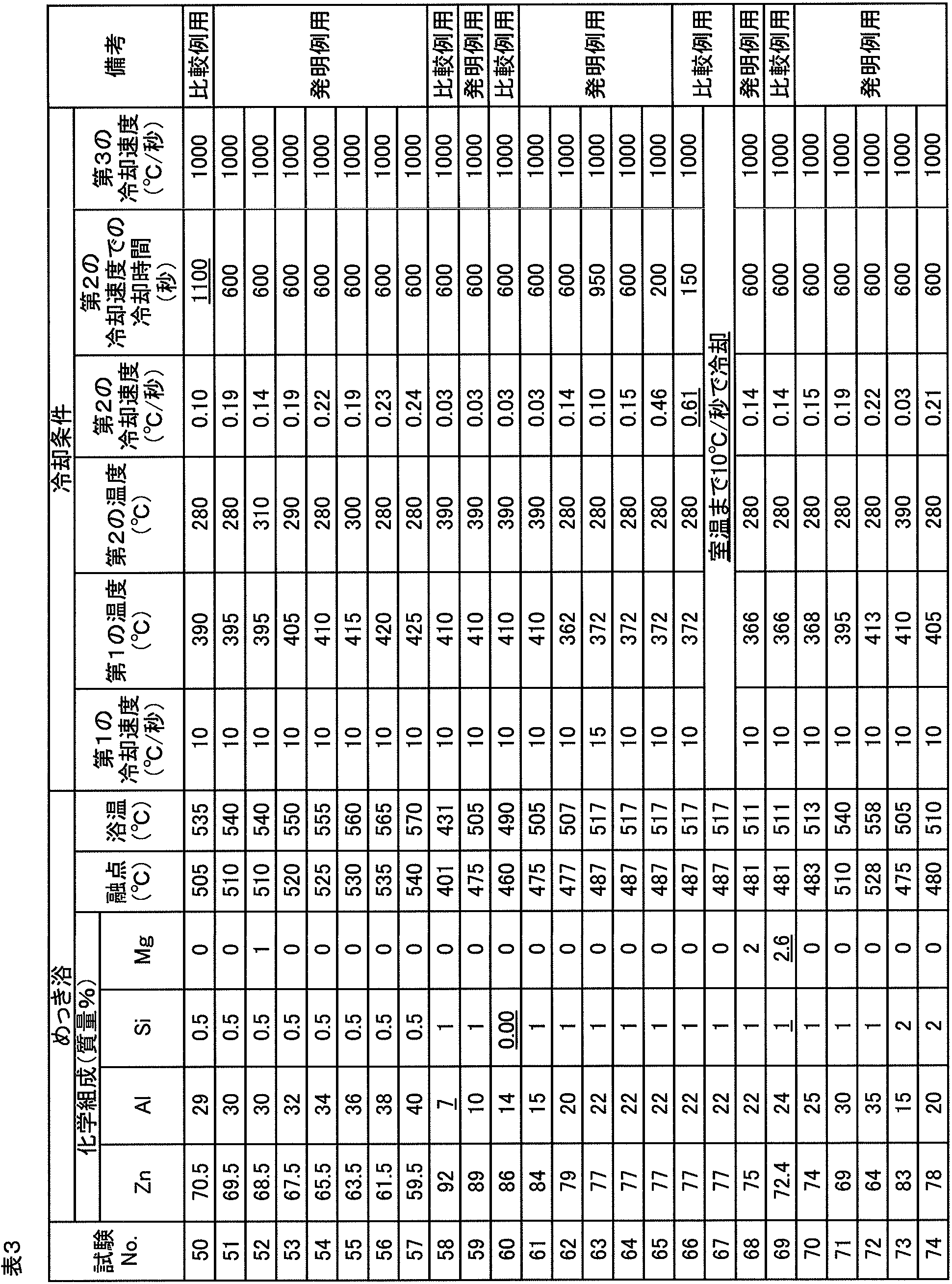
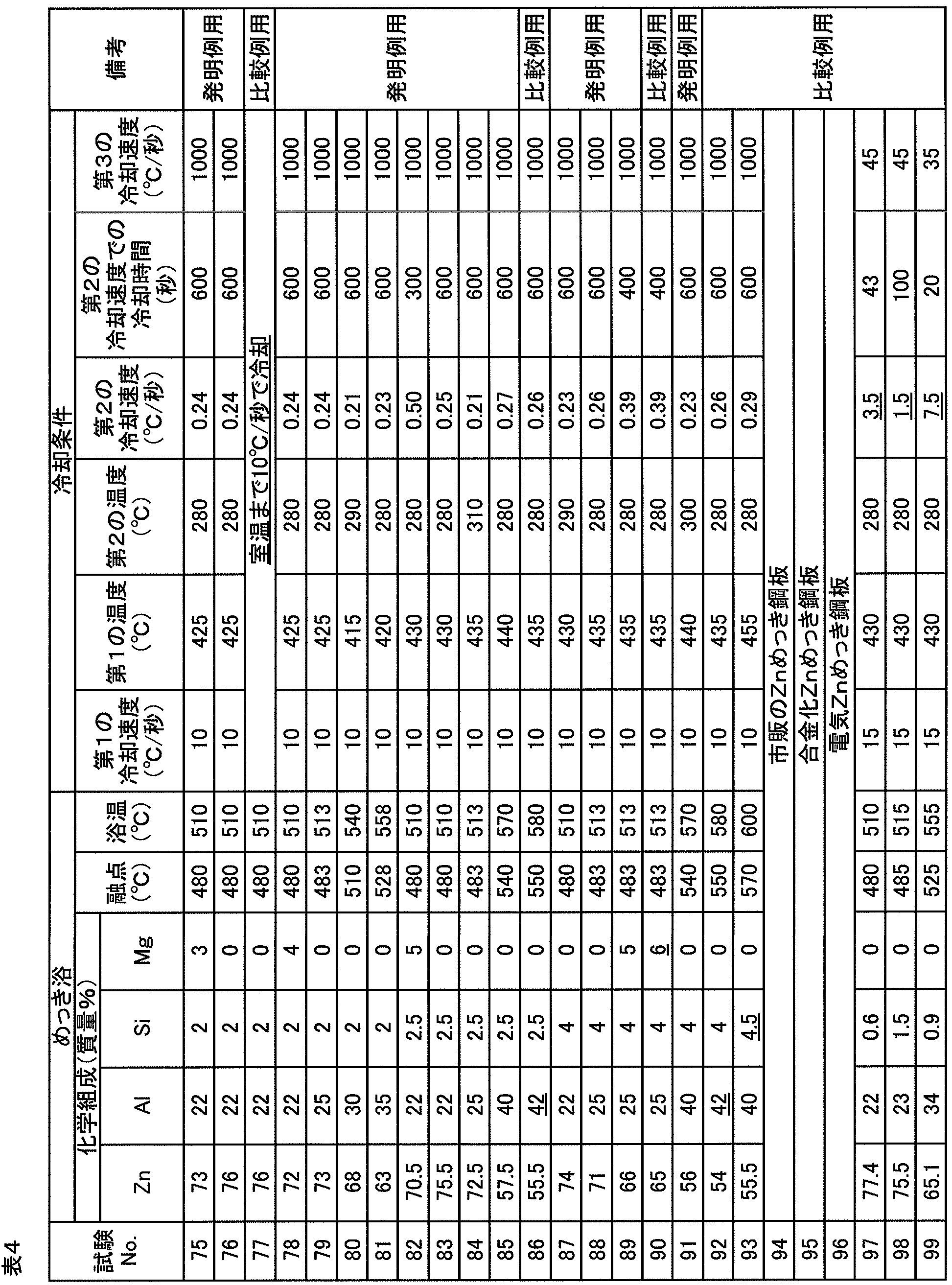
- a plating bath having the chemical composition shown in Tables 1 to 4 was constructed. Tables 1 to 4 also show the melting point and temperature (plating bath temperature) of each plating bath. Further, a cold rolled steel sheet having a C concentration of 0.2% and a plate thickness of 0.8 mm was cut to obtain a plating original plate having a width of 100 mm and a length of 200 mm. Then, in a furnace having an oxygen concentration of 20 ppm or less and a temperature of 800 ° C., the surface of the plating original plate is reduced using a mixed gas of 95 volume% N 2 -5 volume% H 2 , and the plating original sheet is air-cooled with N 2 gas.
- the plating original plate When the temperature of the plating original plate reached the plating bath temperature + 20 ° C., the plating original plate was immersed in the plating bath for about 3 seconds. After immersion in the plating bath, the plating original plate with the molten metal adhered was pulled up at a rate of 100 mm / second while adjusting the plating adhesion amount with N 2 wiping gas. The plate temperature was monitored using a thermocouple spot welded to the center of the plating plate.
- the plating layer was cooled to room temperature under the conditions shown in Tables 1 to 4. That is, gas cooling is performed from the plating bath temperature to the first temperature at the first cooling rate, cooling is performed from the first temperature to the second temperature at the second cooling rate, and then, from the second temperature to room temperature. Cooled at a cooling rate of 3. In this way, various plated steel sheets were obtained.
- the underline in Tables 1 to 4 indicates that the item is outside the desired range.
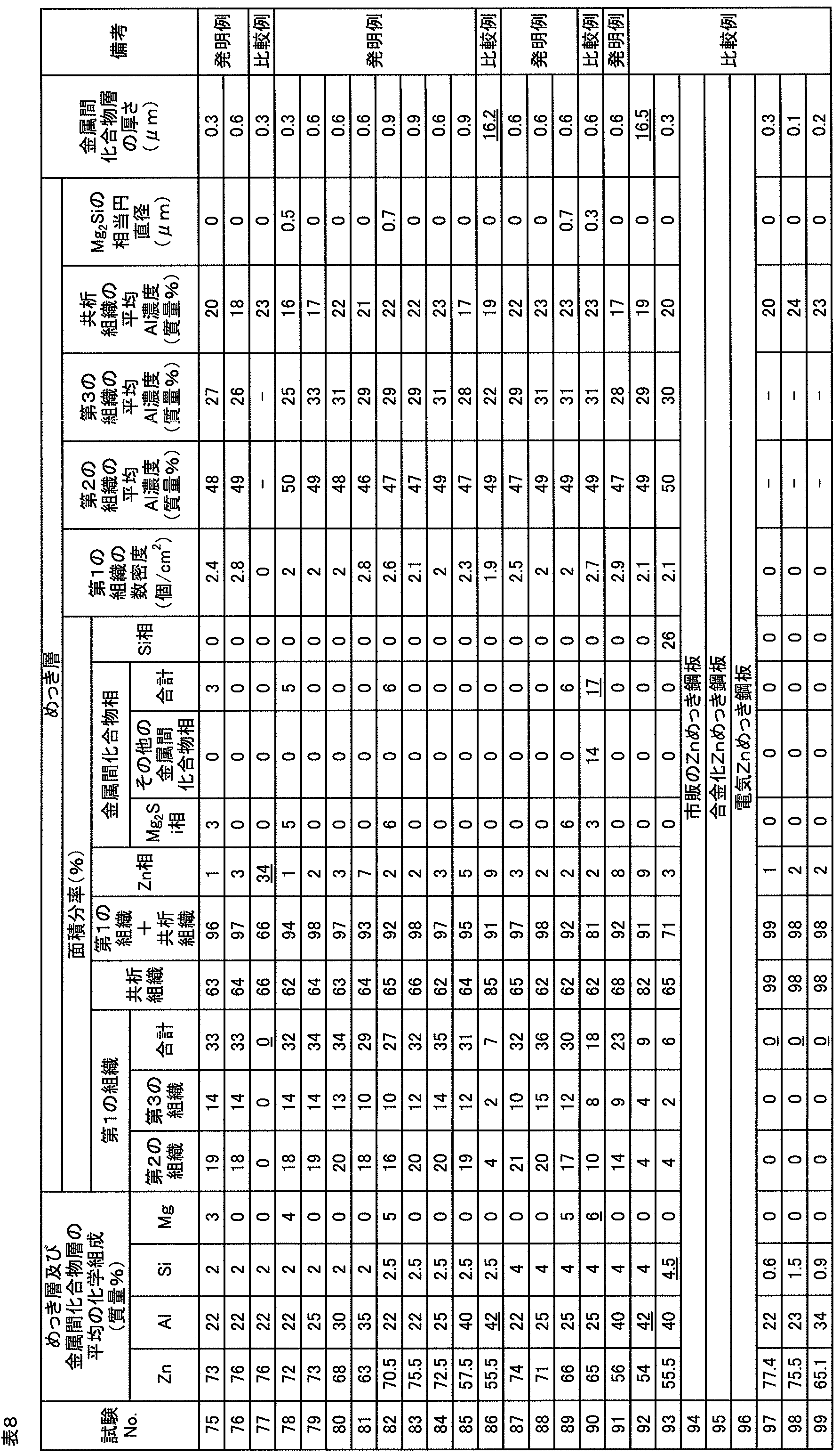
- each plated steel sheet was immersed in HCl with a concentration of 10% to which an inhibitor was added, and the peeling solution was analyzed by the ICP method to identify the average chemical composition of the plating layer and the intermetallic compound layer.
- Each plated steel sheet was cut to prepare five test pieces having a width of 15 mm and a length of 25 mm, and each test piece was embedded in a resin and polished. Then, about each test piece, the element mapping image by the SEM image and EDS of the cross section of a plating layer was obtained.
- the second structure, the third structure, the eutectoid structure, the Zn phase, the intermetallic compound layer, the Mg 2 Si phase, Si in the laminated body of the plating layer and the intermetallic compound layer was measured. Specifically, one field of view was photographed per sample, that is, a total of five fields of view were photographed per plated steel sheet, and the area fraction was measured by image analysis. Each visual field includes an area having a size of 50 ⁇ m ⁇ 200 ⁇ m of the plating layer.
- an EDS analysis is performed on a structure that can be recognized as one of the second structure, the third structure, or the eutectoid structure from the element mapping image by EDS.
- the average Al concentration is specified, and when the average Al concentration is 37% to 50%, the second structure is determined, and when 25% to 36% is the third structure, 10% to 24% is determined as the eutectoid structure. did.
- a structure composed of two phases of an Al phase and a Zn phase with an average crystal grain size of an equivalent circle radius of 1 ⁇ m or less is recognized as one of the second structure, the third structure, and the eutectoid structure. It was.
- each plated steel sheet was evaluated for powdering resistance, chipping resistance, seizure resistance, plastic deformability, and post-coating corrosion resistance.
- each plated steel sheet was cut to produce a test piece having a width of 40 mm, a length of 100 mm, and a thickness of 0.8 mm.
- a 60 ° bending test was performed using the plate width direction as the bending axis direction and the radius of curvature of 5 mmR. Subsequently, the width (peeling width) of the plating layer peeled off by the adhesive tape at 5 points was measured, and the average value (average peeling width) was calculated.
- an average peel width of 0.1 mm or less is “A”
- an average peel width is more than 0.1 mm and 1.0 mm or less “B”
- an average peel width is more than 1.0 mm and 2.0 mm or less
- an average peel width of more than 2.0 mm was evaluated as “D”.
- each plated steel sheet was cut to prepare two test pieces having a width of 80 mm and a length of 350 mm, and each test piece was drawn using a jig imitating a die and a bead. Processing was performed, and a slide having a length of 150 mm or more was generated between the surface of the test piece and the shoulder portion of the die and the bead portion.
- the radius of curvature of the die shoulder portion and the bead portion of the jig was 2 mmR and 5 mmR, the die pressing pressure was 60 kN / m 2 , and the draw bead processing drawing speed was 2 m / min.
- a lubricating oil (550F: manufactured by Nihon Parkerizing Co., Ltd.) was applied to both surfaces at 0.5 g / m 2 on the surface of the test piece. Then, by visually observing the plating layer adhered to the jig, “A” indicates that the plating layer has not adhered, “B” indicates that the plating layer has adhered to the powder, and the plating layer has a strip shape. The adhered one was evaluated as “C”, and the plated layer was peeled as a whole and adhered as “D”.
- each plated steel sheet is cut to prepare a test piece having a width of 30 mm, a length of 60 mm, and a thickness of 0.8 mm, and each test piece is subjected to 0T bending test and 1T bending. Tests and 2T bend tests were performed. Subsequently, the area
- test pieces were prepared for each of the 0T bending test, 1T bending test, and 2T bending test, and the average number of cracks was calculated.
- “A” indicates that the average number of cracks is 0
- “B” indicates that the average number of cracks is 1 to 20
- 21 to 100 is the average number of cracks.
- each plated steel sheet was cut to prepare a sample having a width of 50 mm and a length of 100 mm, and each sample was subjected to a zinc phosphate-based chemical conversion treatment solution (Surfyne SD5350 series: Nippon Paint). -Zinc phosphate treatment using Industrial Coating) was performed. Subsequently, electrodeposition coating using a paint (Powernics 110F system: manufactured by Nihon Parkerizing Co., Ltd.) was performed to form a 20 ⁇ m coating film, and baking was performed at a temperature of 150 ° C. for 20 minutes.
- a paint Powernics 110F system: manufactured by Nihon Parkerizing Co., Ltd.
- the intermediate coating, top coating and clear coating are performed, and the overall film thickness
- the coating film was produced so that might be set to 40 micrometers.
- 100 g of No. 7 crushed stone was applied to a coating film cooled to ⁇ 20 ° C. at an air pressure of 3.0 kg / cm 2 from a distance of 30 cm at an angle of 90 degrees. It was made to collide and the degree of peeling was observed visually.
- A indicates that there is no peeling
- B indicates that the peeling area is small and the peeling frequency is low
- C indicates that the peeling area is large and the peeling frequency is low
- C indicates that the peeling area is large and the peeling frequency is high.
- D indicates that the peeling area is large and the peeling frequency is high.
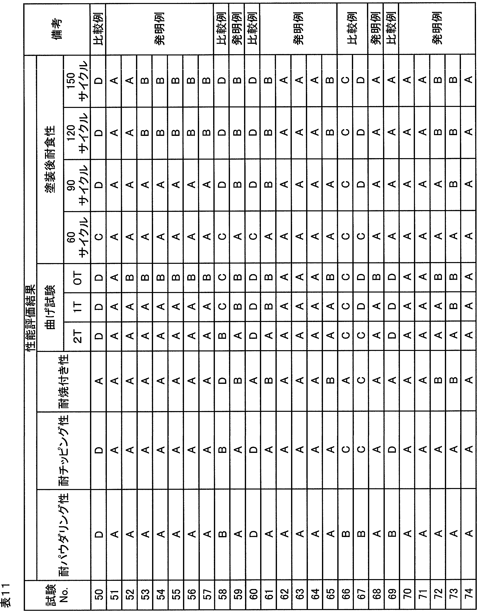
- Tables 9 to 12 show the evaluation results of powdering resistance, chipping resistance, seizure resistance, plastic deformability and post-coating corrosion resistance.
- the MgZn 2 phase which is an intermetallic compound phase, was excessively contained in the plating layer, and sufficient powdering resistance, chipping resistance, and plastic deformation No performance was obtained.
- test no. In No. 32 since the Al concentration of the plating bath was excessive, the intermetallic compound layer was formed thick, and sufficient powdering resistance, chipping resistance, plastic deformability, and corrosion resistance after coating could not be obtained.
- Test No. In No. 40 since the Si concentration in the plating bath was insufficient, the intermetallic compound layer grew immediately after immersion in the plating bath, the intermetallic compound layer was formed thick, and sufficient chipping resistance and plastic deformability were not obtained. .
- Test No. In No. 43 since the second cooling rate was excessive, the area fraction of the first structure was insufficient, and sufficient chipping resistance, plastic deformability and post-coating corrosion resistance were not obtained. Sample No. In No.
- test no. In No. 50 since the time taken for cooling at the second cooling rate was too long, the intermetallic compound layer was formed thick, and sufficient post-coating corrosion resistance, plastic deformability, powdering resistance and chipping resistance could not be obtained. It was. Sample No. In No. 58, since the Al concentration of the plating bath was insufficient, the area fraction of the first structure was insufficient, the intermetallic compound layer was formed thick, and sufficient seizure resistance, plastic deformability, and corrosion resistance after coating could not be obtained. It was. Sample No. In No. 60, since the Si concentration in the plating bath was insufficient, the intermetallic compound layer grew immediately after being immersed in the plating bath, and the intermetallic compound layer was formed thick.
- the MgZn 2 phase which is an intermetallic compound phase, was excessively contained in the plating layer, and sufficient chipping resistance and plastic deformability could not be obtained. It was.
- test no. In No. 77 since the cooling after the plating treatment was performed at a cooling rate of 10 ° C./second to room temperature, the area fraction of the first structure was insufficient, the area fraction of the Zn phase was excessive, and sufficient chipping resistance was achieved. , Seizure resistance, plastic deformability and post-coating corrosion resistance were not obtained. Test No. In 86, since the Al concentration in the plating bath was excessive, the intermetallic compound layer was formed thick, and sufficient powdering resistance, chipping resistance, plastic deformability, and corrosion resistance after coating could not be obtained. Test No. In No.
- FIG. 3 shows a test No. which is an invention example.
- FIG. 4 shows the temperature change (heat pattern) of the plated steel sheet when the 16 plated steel sheet is manufactured.
- the BSE image of 16 plated steel plates is shown.
- the BSE image of 91 plated steel sheets is shown.
- the test No. 1 in which the Al concentration of the plating layer is 22% is shown.
- the first structure 11, the eutectoid structure 14, and the Zn phase 15 exist in appropriate area fractions as in the embodiment shown in FIG. 1, and the second structure is included in the first structure 11.
- 12 and a third tissue 13 are included.
- FIG. 6 shows a test No. as a comparative example.
- FIG. 7 shows the change in temperature (heat pattern) of the plated steel sheet when the 20 plated steel sheet is manufactured. The BSE image of 20 plated steel plates is shown. As shown in FIG. 7, the first structure 11 did not exist, and the area fraction of the Zn phase 15 was high.
- the present invention can be used, for example, in industries related to plated steel sheets suitable for automobile outer plates.
Landscapes
- Chemical & Material Sciences (AREA)
- Engineering & Computer Science (AREA)
- Materials Engineering (AREA)
- Mechanical Engineering (AREA)
- Metallurgy (AREA)
- Organic Chemistry (AREA)
- Chemical Kinetics & Catalysis (AREA)
- Coating With Molten Metal (AREA)
Abstract
Description
少なくとも鋼板の表面の一部にAl含有Zn系のめっき層を有するめっき鋼板であって、
前記めっき層、及び前記めっき層と前記鋼板との間の金属間化合物層の平均の化学組成は、質量%で、Al:10%~40%、Si:0.05%~4%、Mg:0%~5%、かつ残部:Zn及び不純物で表され、
前記めっき層は、
Znを固溶するAl相及びこのAl相中に分散するZn相から構成され、平均の化学組成が、質量%で、Al:25%~50%、Zn:50%~75%、かつ不純物:2%未満で表される第1の組織と、
Al相及びZn相から構成され、平均の化学組成が、質量%で、Al:10%~24%、Zn:76%~90%、不純物:2%未満で表される共析組織と、
を有し、
前記めっき層の断面において、前記第1の組織の面積分率は5%~40%、前記第1の組織及び前記共析組織の合計の面積分率は50%以上であり、
前記めっき層に含まれる、Znを90%以上含む組織であるZn相の面積分率が25%以下であり、
前記めっき層に含まれる、金属間化合物相の合計の面積分率が9%以下であり、
前記金属間化合物層の厚さが2μm以下である、
ことを特徴とするめっき鋼板。
前記めっき層の表面において前記第1の組織の数密度が1.6個/cm2~25.0個/cm2である、
ことを特徴とする(1)に記載のめっき鋼板。
前記第1の組織は、
平均の化学組成が、質量%で、Al:37%~50%、Zn:50%~63%、不純物:2%未満で表される第2の組織と、
平均の化学組成が、質量%で、Al:25%~36%、Zn:64%~75%、不純物:2%未満で表される第3の組織と、
含むことを特徴とする(1)又は(2)に記載のめっき鋼板。
前記めっき層及び前記金属間化合物層の平均の化学組成は、質量%で、Al:20%~40%、Si:0.05%~2.5%、Mg:0%~2%、かつ残部:Zn及び不純物で表される、
ことを特徴とする(1)~(3)のいずれかに記載のめっき鋼板。
前記金属間化合物層の厚さが100nm~1000nmである、
ことを特徴とする(1)~(4)のいずれかに記載のめっき鋼板。
前記めっき層の断面において、前記第1の組織の面積分率は20%~40%、前記共析組織の面積分率は50%~70%、前記第1の組織及び前記共析組織の合計の面積分率は90%以上である、
ことを特徴とする(1)~(5)のいずれかに記載のめっき鋼板。
前記めっき層の断面において、前記第1の組織の面積分率は30%~40%、前記共析組織の面積分率は55%~65%、前記第1の組織及び前記共析組織の合計の面積分率は95%以上である、
ことを特徴とする(1)~(6)のいずれかに記載のめっき鋼板。
前記めっき層及び前記金属間化合物層の平均の化学組成において、Mg濃度が0.05%~5%であり、
Mg濃度をMg%、Si濃度をSi%としたときに、「Mg%≦2×Si%」の関係が成り立ち、
前記めっき層中に存在するMg2Siの結晶が最大相当円直径で2μm以下である、
ことを特徴とする(1)~(7)のいずれかに記載のめっき鋼板。
前記めっき層に含まれる、前記Zn相の体積分率が20%以下であることを特徴とする(1)~(8)のいずれかに記載のめっき鋼板。
Alは、Al含有Zn系のめっき層の融点の上昇及び硬度の向上に寄与する。めっき層の融点が高いほど、プレス成形時の焼付きが生じにくい。Al濃度が10%未満では、めっき層の融点が純Znのめっき層の融点よりも高くならず、焼付きを十分に抑制できない。従って、Al濃度は10%以上とし、好ましくは20%以上とする。Al濃度が10%以上では、Al濃度が高いほどZn-Al合金の融点が高く、Al濃度が40%程度のZn-Al合金の融点は約540℃である。
Siは、めっき層の形成時に、めっき浴に含まれるZn及びAlと、めっき原板である鋼板に含まれるFeとの反応を抑制し、めっき層と鋼板との間への金属間化合物層の生成を抑制する。詳細は後述するが、金属間化合物層は、例えばAl-Zn-Fe化合物を含み、界面合金層ともよばれ、めっき層と鋼板との間の密着性を低下させたり、加工性を低下させたりする。めっき浴に含まれるSiの濃度が0.05%未満では、めっき原板をめっき浴に浸漬すると直ちに金属間化合物層が成長し始め、過剰な金属間化合物層が形成されて加工性の低下が顕著となる。従って、めっき浴におけるSi濃度は0.05%以上とし、めっき層及び金属間化合物層における平均のSi濃度も0.05%以上とする。一方、Si濃度が4%超では、破壊の起点となるSi相がめっき層に残存しやすく、十分な延性が得られないことがある。従って、Si濃度は4%以下とし、好ましくは2%以下とする。
Mgは、塗装後耐食性の向上に寄与する。例えば、めっき層中にMgが含有されると、塗膜及びめっき層にカット傷があっても、カット傷からの腐食を抑制することができる。これは、腐食に伴ってMgが溶出することで、カット傷の周囲にMgを含む腐食生成物が生成し、自己修復作用のようにカット傷からの、水、酸素等の腐食因子の更なる侵入を防ぐためである。この腐食を抑制する効果は、Mg濃度が0.05%以上で顕著である。従って、Mg濃度は、好ましくは0.05%以上であり、より好ましくは1%以上である。一方、Mgは、MgZn2又はMg2Si等の加工性に乏しい金属間化合物を形成しやすい。Siがめっき層に含まれている場合、Mg2SiがMgZn2よりも優先的に析出する傾向がある。これらの金属間化合物が多いほど加工性が低く、Mg濃度が5%超でめっき層の延性の低下が顕著である。従って、Mg濃度は5%以下とし、好ましくは2%以下とする。
Znは、めっき層の犠牲防食能、耐食性及び塗装下地の性能の向上に寄与する。Al及びZnでめっき層の大半を占めていることが好ましい。不純物としては、例えば、鋼板から拡散してきたFe、めっき浴に不可避的に含まれる元素が挙げられる。
第1の組織は、Znを固溶するAl相及びこのAl相中に分散するZn相から構成され、平均の化学組成が、Al:25%~50%、Zn:50%~75%、かつ不純物:2%未満で表される組織である。第1の組織は、塑性変形能、加工性及び耐チッピング性の向上に寄与する。めっき層の断面において、第1の組織の面積分率が5%未満では、十分な加工性が得られない。従って、第1の組織の面積分率は5%以上とし、好ましくは20%以上とし、より好ましくは30%以上とする。その一方で、後述の方法で形成できる第1の組織の面積分率は多くとも40%である。
共析組織は、Al相及びZn相から構成され、平均の化学組成が、Al:10%~24%、Zn:76%~90%、不純物:2%未満で表される組織である。共析組織も、塑性変形能の向上に寄与する。めっき層の断面において、共析組織の面積分率が50%未満では、Zn相の割合が高くなり、十分なプレス成形性及び塗装後耐食性が得られないことがある。従って、共析組織の面積分率は、好ましくは50%以上とし、より好ましくは55%以上とする。その一方で、後述の方法で形成できる共析組織の面積分率は多くとも75%である。加工性の向上に共析組織よりも寄与しやすい第1の組織をより高い面積分率で得るために、共析組織の面積分率は、好ましくは70%以下とし、より好ましくは65%以下とする。
Znを90%以上含む組織であるZn相は、加工性を低下させる。めっき層に、第1の組織、共析組織及びZn相以外の相、例えば、Si相及びMg2Si相が含まれていてもよく、その他の金属間化合物相(MgZn2相等)が含まれていてもよいが、これらも加工性を低下させる。従って、めっき層にZn相及び金属間化合物相が含まれないことが好ましい。そして、Zn相の面積分率は25%超で、加工性の低下が顕著であり、金属間化合物相の合計の面積分率が9%超で加工性の低下が顕著である。従って、Zn相の面積分率は25%以下とし、金属間化合物相の合計の面積分率は9%以下とする。耐食性の観点からも、好ましくはZn相の面積分率は20%以下である。また、より高い延性を確保する観点から、Si相の面積分率は、好ましくは3%以下である。
Al濃度が20%以上40%以下の場合、めっき浴温から360℃~435℃の範囲内の第1の温度まで10℃/秒以上の第1の冷却速度で冷却し、第1の温度から280℃~310℃の範囲内の第2の温度まで0.02℃/秒~0.50℃/秒の第2の冷却速度で冷却し、その後、第2の温度から室温まで30℃/秒以上の第3の冷却速度で冷却する。
Al濃度が10%以上20%未満の場合、めっき浴温から410℃の第1の温度まで10℃/秒以上の第1の冷却速度で冷却し、第1の温度から390℃の第2の温度まで0.02℃/秒~0.11℃/秒の第2の冷却速度で冷却し、その後、第2の温度から室温まで30℃/秒以上の第3の冷却速度で冷却する。
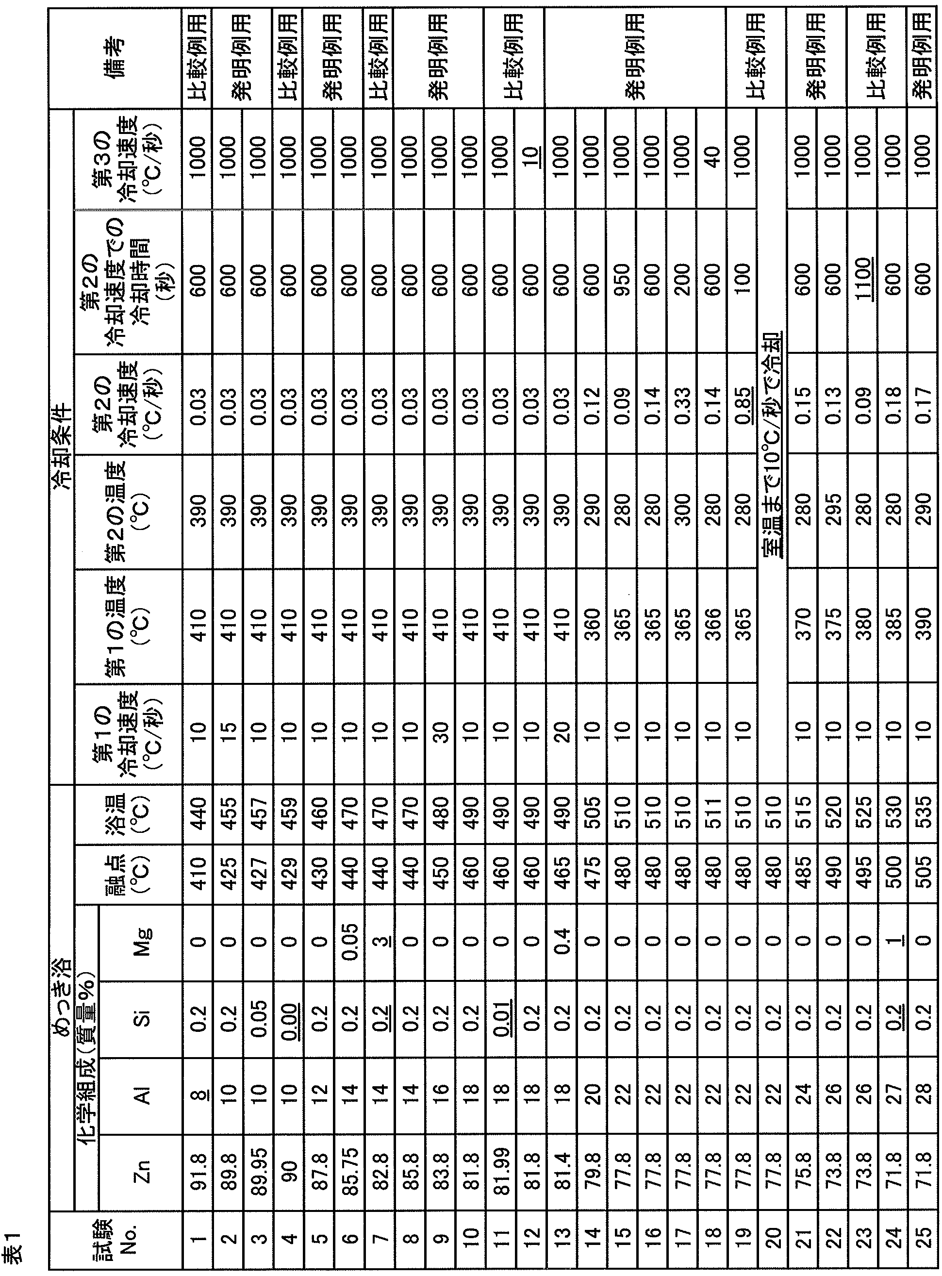


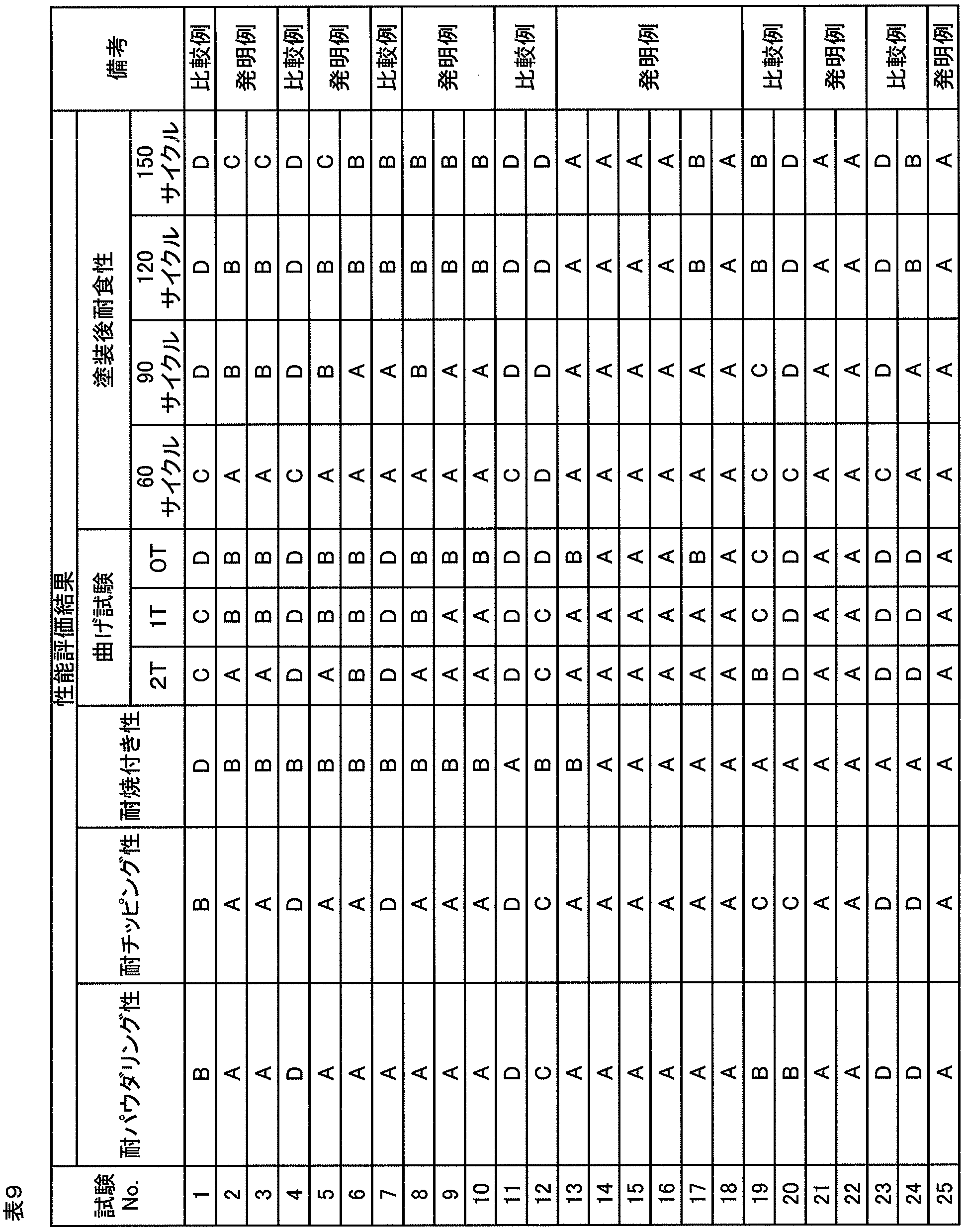


試験No.4では、めっき浴のSi濃度が不足したため、めっき浴への浸漬直後から金属間化合物層が成長し、金属間化合物層が厚く形成され、十分な耐パウダリング性、耐チッピング性、塑性変形能及び塗装後耐食性が得られなかった。
試験No.7では、めっき浴のMg濃度がSi濃度に対して過剰であったため、金属間化合物相であるMgZn2相がめっき層に過剰に含まれ、十分な耐チッピング性及び塑性変形能が得られなかった。
試験No.11では、めっき浴のSi濃度が不足したため、めっき浴への浸漬直後から金属間化合物層が成長し、金属間化合物層が厚く形成され、十分な耐パウダリング性、耐チッピング性、塑性変形能及び塗装後耐食性が得られなかった。
試験No.12では、第3の冷却速度が不足したため、第1の組織の面積分率が不足し、Zn相の面積分率が過剰であり、十分な耐パウダリング性、耐チッピング性、塑性変形能及び塗装後耐食性が得られなかった。
試験No.19では、第2の冷却速度が過剰であったため、第1の組織の面積分率が不足し、1T曲げ試験及び0T曲げ試験にて多くのクラックが発生し、十分な塑性変形能が得られなかった。また、十分な耐チッピング性及び塗装後耐食性も得られなかった。
試験No.20では、めっき処理後の冷却を室温まで10℃/秒の冷却速度で行ったため、第1の組織の面積分率が不足し、Zn相の面積分率が過剰であり、十分な耐チッピング性、塑性変形能及び塗装後耐食性が得られなかった。
試験No.23では、第2の冷却速度での冷却にかけた時間が長すぎたため、金属間化合物層が厚く形成され、十分な塗装後耐食性、塑性変形能、耐パウダリング性及び耐チッピング性が得られなかった。
試験No.24では、めっき浴のMg濃度がSi濃度に対して過剰であったため、金属間化合物相であるMgZn2相がめっき層に過剰に含まれ、十分な耐パウダリング性、耐チッピング性及び塑性変形能が得られなかった。
試験No.40では、めっき浴のSi濃度が不足したため、めっき浴への浸漬直後から金属間化合物層が成長し、金属間化合物層が厚く形成され、十分な耐チッピング性及び塑性変形能が得られなかった。
試験No.43では、第2の冷却速度が過剰であったため、第1の組織の面積分率が不足し、十分な耐チッピング性、塑性変形能及び塗装後耐食性が得られなかった。
試料No.44では、めっき処理後の冷却を室温まで10℃/秒の冷却速度で行ったため、第1の組織の面積分率が不足し、Zn相の面積分率が過剰であり、十分な耐チッピング性、耐焼付き性、塑性変形能及び塗装後耐食性が得られなかった。
試料No.45では、めっき浴のMg濃度がSi濃度に対して過剰であったため、金属間化合物相であるMgZn2相がめっき層に過剰に含まれ、十分な耐チッピング性及び塑性変形能が得られなかった。
試料No.48では、めっき浴のMg濃度がSi濃度に対して過剰であったため、金属間化合物相であるMgZn2相がめっき層に過剰に含まれ、十分な耐チッピング性及び塑性変形能が得られなかった。
試料No.58では、めっき浴のAl濃度が不足したため、第1の組織の面積分率が不足し、金属間化合物層が厚く形成され、十分な耐焼付き性、塑性変形能及び塗装後耐食性が得られなかった。
試料No.60では、めっき浴のSi濃度が不足したため、めっき浴への浸漬直後から金属間化合物層が成長し、金属間化合物層が厚く形成され、十分な耐パウダリング性、耐チッピング性、塑性変形能及び塗装後耐食性が得られなかった。
試料No.66では、第2の冷却速度が過剰であったため、第1の組織の面積分率が不足し、十分な耐チッピング性、塑性変形能及び塗装後耐食性が得られなかった。
試料No.67では、めっき処理後の冷却を室温まで10℃/秒の冷却速度で行ったため、第1の組織の面積分率が不足し、Zn相の面積分率が過剰であり、十分な耐チッピング性、耐焼付き性、塑性変形能及び塗装後耐食性が得られなかった。
試料No.69では、めっき浴のMg濃度がSi濃度に対して過剰であったため、金属間化合物相であるMgZn2相がめっき層に過剰に含まれ、十分な耐チッピング性及び塑性変形能が得られなかった。
試験No.86では、めっき浴のAl濃度が過剰であったため、金属間化合物層が厚く形成され、十分な耐パウダリング性、耐チッピング性、塑性変形能及び塗装後耐食性が得られなかった。
試験No.90では、めっき浴のMg濃度が過剰であったため、金属間化合物相であるMgZn2相がめっき層に過剰に含まれ、十分な耐パウダリング性、耐チッピング性及び塑性変形能が得られなかった。
試験No.92では、めっき浴のAl濃度が過剰であったため、金属間化合物層が厚く形成され、十分な耐パウダリング性、耐チッピング性、塑性変形能及び塗装後耐食性が得られなかった。
試験No.93では、Si濃度が過剰であったため、めっき層にSi相が多く含まれ、十分な耐チッピング性、耐焼付き性及び塑性変形能が得られなかった。
試験No.94の市販のZnめっき鋼板は、耐焼付き性及び長期の塗装後耐食性に劣っていた。
試験No.95の合金化Znめっき鋼板では、耐パウダリング性、耐チッピング性、塑性変形能及び塗装後耐食性の全般にわたり、性能が劣っていた。
試験No.96の電気Znめっき鋼板は、めっき層厚さが小さいこともあって、耐焼付き性及び塗装後耐食性に劣っていた。
比較例である試験No.97~No.99では、第2の冷却速度が過剰であったため、第1の組織の面積分率が不足し、十分な耐パウダリング性、耐チッピング性、塑性変形能及び塗装後耐食性が得られなかった。
Claims (9)
- 少なくとも鋼板の表面の一部にAl含有Zn系のめっき層を有するめっき鋼板であって、
前記めっき層、及び前記めっき層と前記鋼板との間の金属間化合物層の平均の化学組成は、質量%で、Al:10%~40%、Si:0.05%~4%、Mg:0%~5%、かつ残部:Zn及び不純物で表され、
前記めっき層は、
Znを固溶するAl相及びこのAl相中に分散するZn相から構成され、平均の化学組成が、質量%で、Al:25%~50%、Zn:50%~75%、かつ不純物:2%未満で表される第1の組織と、
Al相及びZn相から構成され、平均の化学組成が、質量%で、Al:10%~24%、Zn:76%~90%、不純物:2%未満で表される共析組織と、
を有し、
前記めっき層の断面において、前記第1の組織の面積分率は5%~40%、前記第1の組織及び前記共析組織の合計の面積分率は50%以上であり、
前記めっき層に含まれる、Znを90%以上含む組織であるZn相の面積分率が25%以下であり、
前記めっき層に含まれる、金属間化合物相の合計の面積分率が9%以下であり、
前記金属間化合物層の厚さが2μm以下である、
ことを特徴とするめっき鋼板。 - 前記めっき層の表面において前記第1の組織の数密度が1.6個/cm2~25.0個/cm2である、
ことを特徴とする請求項1に記載のめっき鋼板。 - 前記第1の組織は、
平均の化学組成が、質量%で、Al:37%~50%、Zn:50%~63%、不純物:2%未満で表される第2の組織と、
平均の化学組成が、質量%で、Al:25%~36%、Zn:64%~75%、不純物:2%未満で表される第3の組織と、
含むことを特徴とする請求項1又は2に記載のめっき鋼板。 - 前記めっき層及び前記金属間化合物層の平均の化学組成は、質量%で、Al:20%~40%、Si:0.05%~2.5%、Mg:0%~2%、かつ残部:Zn及び不純物で表される、
ことを特徴とする請求項1乃至3のいずれか1項に記載のめっき鋼板。 - 前記金属間化合物層の厚さが100nm~1000nmである、
ことを特徴とする請求項1乃至4のいずれか1項に記載のめっき鋼板。 - 前記めっき層の断面において、前記第1の組織の面積分率は20%~40%、前記共析組織の面積分率は50%~70%、前記第1の組織及び前記共析組織の合計の面積分率は90%以上である、
ことを特徴とする請求項1乃至5のいずれか1項に記載のめっき鋼板。 - 前記めっき層の断面において、前記第1の組織の面積分率は30%~40%、前記共析組織の面積分率は55%~65%、前記第1の組織及び前記共析組織の合計の面積分率は95%以上である、
ことを特徴とする請求項1乃至6のいずれか1項に記載のめっき鋼板。 - 前記めっき層及び前記金属間化合物層の平均の化学組成において、Mg濃度が0.05%~5%であり、
Mg濃度をMg%、Si濃度をSi%としたときに、「Mg%≦2×Si%」の関係が成り立ち、
前記めっき層中に存在するMg2Siの結晶が最大相当円直径で2μm以下である、
ことを特徴とする請求項1乃至7のいずれか1項に記載のめっき鋼板。 - 前記めっき層に含まれる、前記Zn相の体積分率が20%以下であることを特徴とする請求項1乃至8のいずれか1項に記載のめっき鋼板。
Priority Applications (9)
| Application Number | Priority Date | Filing Date | Title |
|---|---|---|---|
| US15/753,150 US10655203B2 (en) | 2015-10-26 | 2016-10-25 | Plated steel sheet |
| CN201680060755.8A CN108350554B (zh) | 2015-10-26 | 2016-10-25 | 镀覆钢板 |
| BR112018003781-8A BR112018003781A2 (ja) | 2015-10-26 | 2016-10-25 | Plating steel plate |
| MX2018002518A MX2018002518A (es) | 2015-10-26 | 2016-10-25 | Lamina de acero enchapada. |
| PL16859809T PL3369837T3 (pl) | 2015-10-26 | 2016-10-25 | Blacha stalowa cienka powlekana galwanicznie |
| KR1020187007029A KR102085223B1 (ko) | 2015-10-26 | 2016-10-25 | 도금 강판 |
| JP2017502901A JP6160793B1 (ja) | 2015-10-26 | 2016-10-25 | めっき鋼板 |
| EP16859809.2A EP3369837B1 (en) | 2015-10-26 | 2016-10-25 | Plated steel sheet |
| ES16859809T ES2778682T3 (es) | 2015-10-26 | 2016-10-25 | Lámina de acero enchapado |
Applications Claiming Priority (2)
| Application Number | Priority Date | Filing Date | Title |
|---|---|---|---|
| JP2015-209674 | 2015-10-26 | ||
| JP2015209674 | 2015-10-26 |
Publications (1)
| Publication Number | Publication Date |
|---|---|
| WO2017073579A1 true WO2017073579A1 (ja) | 2017-05-04 |
Family
ID=58630504
Family Applications (1)
| Application Number | Title | Priority Date | Filing Date |
|---|---|---|---|
| PCT/JP2016/081634 WO2017073579A1 (ja) | 2015-10-26 | 2016-10-25 | めっき鋼板 |
Country Status (11)
| Country | Link |
|---|---|
| US (1) | US10655203B2 (ja) |
| EP (1) | EP3369837B1 (ja) |
| JP (1) | JP6160793B1 (ja) |
| KR (1) | KR102085223B1 (ja) |
| CN (1) | CN108350554B (ja) |
| BR (1) | BR112018003781A2 (ja) |
| ES (1) | ES2778682T3 (ja) |
| MX (1) | MX2018002518A (ja) |
| PL (1) | PL3369837T3 (ja) |
| TW (1) | TWI601853B (ja) |
| WO (1) | WO2017073579A1 (ja) |
Cited By (4)
| Publication number | Priority date | Publication date | Assignee | Title |
|---|---|---|---|---|
| EP3733917A4 (en) * | 2017-12-28 | 2021-04-21 | Nippon Steel Corporation | SHEET STEEL COATED WITH MELTED ZINC BASED VENEER WITH SUPERIOR CORROSION RESISTANCE AFTER COATING |
| JP7417103B2 (ja) | 2020-06-09 | 2024-01-18 | 日本製鉄株式会社 | 溶融Zn-Al-Mg系めっき鋼材 |
| JP7417102B2 (ja) | 2020-06-09 | 2024-01-18 | 日本製鉄株式会社 | 溶融Zn-Al-Mg系めっき鋼材 |
| JP7436840B2 (ja) | 2020-06-09 | 2024-02-22 | 日本製鉄株式会社 | 溶融Zn-Al-Mg系めっき鋼材 |
Families Citing this family (3)
| Publication number | Priority date | Publication date | Assignee | Title |
|---|---|---|---|---|
| CN113677820B (zh) * | 2019-04-19 | 2023-10-03 | 日本制铁株式会社 | 镀层钢材 |
| JP7127750B2 (ja) * | 2020-04-21 | 2022-08-30 | 日本製鉄株式会社 | 溶融めっき鋼板、及びその製造方法 |
| CN117280070B (zh) * | 2021-09-07 | 2024-04-19 | 日本制铁株式会社 | 热浸镀钢材 |
Citations (6)
| Publication number | Priority date | Publication date | Assignee | Title |
|---|---|---|---|---|
| JP2002206156A (ja) * | 2000-11-06 | 2002-07-26 | Nippon Steel Corp | 鉄塔用めっき鉄鋼製品とその製造方法および該製造方法で用いるフラックス |
| JP2003155549A (ja) * | 2001-11-19 | 2003-05-30 | Nippon Steel Corp | 高耐食性を有し加工性に優れた亜鉛合金めっき鋼材とその製造方法 |
| JP2003268517A (ja) * | 2002-03-08 | 2003-09-25 | Nippon Steel Corp | 表面平滑性に優れる溶融めっき鋼材 |
| JP2004323974A (ja) * | 2003-04-11 | 2004-11-18 | Jfe Steel Kk | 溶融Zn−Al系合金めっき鋼板およびその製造方法 |
| US20090004400A1 (en) * | 2004-01-22 | 2009-01-01 | Madhu Ranjan | Effect of Ternary Additions on the Structure and Properties of Coatings Produced by a High Aluminum Galvanizing Bath |
| WO2010150537A1 (ja) * | 2009-06-25 | 2010-12-29 | 新日本製鐵株式会社 | 耐食性と疲労特性に優れた橋梁用高強度Zn-Alめっき鋼線及びその製造方法 |
Family Cites Families (13)
| Publication number | Priority date | Publication date | Assignee | Title |
|---|---|---|---|---|
| JP2003253416A (ja) | 2002-02-27 | 2003-09-10 | Jfe Steel Kk | 合金化溶融亜鉛めっき鋼板 |
| US7238431B2 (en) | 2002-03-08 | 2007-07-03 | Nippon Steel Corporation | Highly corrosion-resistant hot dip plated steel material excellent in surface smoothness |
| AU2003275688B2 (en) | 2002-10-28 | 2006-12-14 | Nippon Steel Corporation | High corrosion-resistant hot dip coated steel product excellent in surface smoothness and formability, and method for producing hot dip coated steel product |
| JP4157491B2 (ja) * | 2003-04-25 | 2008-10-01 | 新日本製鐵株式会社 | 加工性に優れた非脱膜型潤滑めっき鋼板 |
| JP2005015834A (ja) * | 2003-06-25 | 2005-01-20 | Nippon Steel Corp | 耐食性に優れ溶接可能な高耐食性塗装鋼板 |
| JP4306426B2 (ja) | 2003-11-27 | 2009-08-05 | Jfeスチール株式会社 | 溶融亜鉛めっき鋼板 |
| JP4374281B2 (ja) | 2004-05-26 | 2009-12-02 | 新日本製鐵株式会社 | 加工部耐食性に優れる溶融めっき鋼材 |
| JP4374289B2 (ja) | 2004-07-07 | 2009-12-02 | 新日本製鐵株式会社 | 加工部耐食性に優れた表面処理鋼板 |
| JP4542434B2 (ja) | 2005-01-14 | 2010-09-15 | 新日本製鐵株式会社 | 表面外観に優れた溶融Zn−Al−Mg−Siめっき鋼板及びその製造方法。 |
| JP4542468B2 (ja) | 2005-06-14 | 2010-09-15 | 日新製鋼株式会社 | 曲げ加工性に優れた溶融Zn−Al−Mg系めっき鋼板の製造方法 |
| CN1804100A (zh) * | 2006-01-20 | 2006-07-19 | 东南大学 | 钢或铁合金材料表面镀锌铝减振合金工艺 |
| JP5404126B2 (ja) | 2009-03-26 | 2014-01-29 | 日新製鋼株式会社 | 耐食性に優れたZn−Al系めっき鋼板およびその製造方法 |
| WO2011001662A1 (ja) | 2009-06-30 | 2011-01-06 | 新日本製鐵株式会社 | Zn-Al-Mg系溶融めっき鋼板とその製造方法 |
-
2016
- 2016-10-25 EP EP16859809.2A patent/EP3369837B1/en active Active
- 2016-10-25 PL PL16859809T patent/PL3369837T3/pl unknown
- 2016-10-25 JP JP2017502901A patent/JP6160793B1/ja active Active
- 2016-10-25 KR KR1020187007029A patent/KR102085223B1/ko active IP Right Grant
- 2016-10-25 WO PCT/JP2016/081634 patent/WO2017073579A1/ja active Application Filing
- 2016-10-25 US US15/753,150 patent/US10655203B2/en active Active
- 2016-10-25 ES ES16859809T patent/ES2778682T3/es active Active
- 2016-10-25 BR BR112018003781-8A patent/BR112018003781A2/ja active Search and Examination
- 2016-10-25 CN CN201680060755.8A patent/CN108350554B/zh active Active
- 2016-10-25 MX MX2018002518A patent/MX2018002518A/es unknown
- 2016-10-26 TW TW105134588A patent/TWI601853B/zh not_active IP Right Cessation
Patent Citations (6)
| Publication number | Priority date | Publication date | Assignee | Title |
|---|---|---|---|---|
| JP2002206156A (ja) * | 2000-11-06 | 2002-07-26 | Nippon Steel Corp | 鉄塔用めっき鉄鋼製品とその製造方法および該製造方法で用いるフラックス |
| JP2003155549A (ja) * | 2001-11-19 | 2003-05-30 | Nippon Steel Corp | 高耐食性を有し加工性に優れた亜鉛合金めっき鋼材とその製造方法 |
| JP2003268517A (ja) * | 2002-03-08 | 2003-09-25 | Nippon Steel Corp | 表面平滑性に優れる溶融めっき鋼材 |
| JP2004323974A (ja) * | 2003-04-11 | 2004-11-18 | Jfe Steel Kk | 溶融Zn−Al系合金めっき鋼板およびその製造方法 |
| US20090004400A1 (en) * | 2004-01-22 | 2009-01-01 | Madhu Ranjan | Effect of Ternary Additions on the Structure and Properties of Coatings Produced by a High Aluminum Galvanizing Bath |
| WO2010150537A1 (ja) * | 2009-06-25 | 2010-12-29 | 新日本製鐵株式会社 | 耐食性と疲労特性に優れた橋梁用高強度Zn-Alめっき鋼線及びその製造方法 |
Cited By (4)
| Publication number | Priority date | Publication date | Assignee | Title |
|---|---|---|---|---|
| EP3733917A4 (en) * | 2017-12-28 | 2021-04-21 | Nippon Steel Corporation | SHEET STEEL COATED WITH MELTED ZINC BASED VENEER WITH SUPERIOR CORROSION RESISTANCE AFTER COATING |
| JP7417103B2 (ja) | 2020-06-09 | 2024-01-18 | 日本製鉄株式会社 | 溶融Zn-Al-Mg系めっき鋼材 |
| JP7417102B2 (ja) | 2020-06-09 | 2024-01-18 | 日本製鉄株式会社 | 溶融Zn-Al-Mg系めっき鋼材 |
| JP7436840B2 (ja) | 2020-06-09 | 2024-02-22 | 日本製鉄株式会社 | 溶融Zn-Al-Mg系めっき鋼材 |
Also Published As
| Publication number | Publication date |
|---|---|
| EP3369837B1 (en) | 2020-02-05 |
| TWI601853B (zh) | 2017-10-11 |
| CN108350554A (zh) | 2018-07-31 |
| ES2778682T3 (es) | 2020-08-11 |
| JPWO2017073579A1 (ja) | 2017-11-02 |
| US20180245193A1 (en) | 2018-08-30 |
| KR20180040157A (ko) | 2018-04-19 |
| US10655203B2 (en) | 2020-05-19 |
| JP6160793B1 (ja) | 2017-07-12 |
| KR102085223B1 (ko) | 2020-03-05 |
| EP3369837A1 (en) | 2018-09-05 |
| BR112018003781A2 (ja) | 2018-09-25 |
| TW201718941A (zh) | 2017-06-01 |
| PL3369837T4 (pl) | 2020-09-21 |
| EP3369837A4 (en) | 2019-06-19 |
| PL3369837T3 (pl) | 2020-09-21 |
| CN108350554B (zh) | 2020-01-21 |
| MX2018002518A (es) | 2018-05-28 |
Similar Documents
| Publication | Publication Date | Title |
|---|---|---|
| JP6160793B1 (ja) | めっき鋼板 | |
| JP6433960B2 (ja) | 溶融Al−Zn−Mg−Siめっき鋼板とその製造方法 | |
| JP6394843B1 (ja) | めっき鋼板 | |
| JP6368730B2 (ja) | 溶融Al−Zn−Mg−Siめっき鋼板とその製造方法 | |
| KR102516012B1 (ko) | 도금 강판 | |
| KR101636443B1 (ko) | 용융 Al-Zn계 도금 강판 및 그의 제조 방법 | |
| JP6350780B1 (ja) | 塗装後耐食性に優れた溶融Zn系めっき鋼板 | |
| WO2016072479A1 (ja) | 溶融亜鉛めっき鋼板 | |
| WO2018221738A1 (ja) | ホットスタンプ部材 | |
| JP6428975B1 (ja) | めっき鋼板 | |
| TW201348512A (zh) | 熱壓用鋼板、其製造方法、以及使用其的熱壓構件的製造方法 | |
| KR20150041167A (ko) | 용융 Al-Zn계 도금 강판 | |
| JP2006336097A (ja) | 焼付硬化性に優れた合金化溶融亜鉛めっき用鋼板及び合金化溶融亜鉛めっき鋼板 |
Legal Events
| Date | Code | Title | Description |
|---|---|---|---|
| ENP | Entry into the national phase |
Ref document number: 2017502901 Country of ref document: JP Kind code of ref document: A |
|
| 121 | Ep: the epo has been informed by wipo that ep was designated in this application |
Ref document number: 16859809 Country of ref document: EP Kind code of ref document: A1 |
|
| WWE | Wipo information: entry into national phase |
Ref document number: 15753150 Country of ref document: US |
|
| WWE | Wipo information: entry into national phase |
Ref document number: MX/A/2018/002518 Country of ref document: MX |
|
| ENP | Entry into the national phase |
Ref document number: 20187007029 Country of ref document: KR Kind code of ref document: A |
|
| REG | Reference to national code |
Ref country code: BR Ref legal event code: B01A Ref document number: 112018003781 Country of ref document: BR |
|
| NENP | Non-entry into the national phase |
Ref country code: DE |
|
| ENP | Entry into the national phase |
Ref document number: 112018003781 Country of ref document: BR Kind code of ref document: A2 Effective date: 20180226 |