WO2017068701A1 - 駐車スペース検出方法および装置 - Google Patents
駐車スペース検出方法および装置 Download PDFInfo
- Publication number
- WO2017068701A1 WO2017068701A1 PCT/JP2015/079895 JP2015079895W WO2017068701A1 WO 2017068701 A1 WO2017068701 A1 WO 2017068701A1 JP 2015079895 W JP2015079895 W JP 2015079895W WO 2017068701 A1 WO2017068701 A1 WO 2017068701A1
- Authority
- WO
- WIPO (PCT)
- Prior art keywords
- parking space
- parking
- vehicle
- space
- control device
- Prior art date
Links
- 238000001514 detection method Methods 0.000 title claims abstract description 55
- 238000000034 method Methods 0.000 description 74
- 230000008569 process Effects 0.000 description 47
- 238000012545 processing Methods 0.000 description 23
- 238000010586 diagram Methods 0.000 description 14
- 238000003384 imaging method Methods 0.000 description 14
- 230000006870 function Effects 0.000 description 7
- 238000004891 communication Methods 0.000 description 5
- 230000007423 decrease Effects 0.000 description 5
- 238000005259 measurement Methods 0.000 description 5
- 240000004050 Pentaglottis sempervirens Species 0.000 description 4
- 235000004522 Pentaglottis sempervirens Nutrition 0.000 description 4
- 230000003247 decreasing effect Effects 0.000 description 2
- 238000003708 edge detection Methods 0.000 description 2
- 230000007246 mechanism Effects 0.000 description 2
- 238000012544 monitoring process Methods 0.000 description 2
- 230000007306 turnover Effects 0.000 description 2
- 230000004888 barrier function Effects 0.000 description 1
- 230000008859 change Effects 0.000 description 1
- 239000003086 colorant Substances 0.000 description 1
- 238000013461 design Methods 0.000 description 1
- 238000011161 development Methods 0.000 description 1
- 238000009434 installation Methods 0.000 description 1
- 238000003825 pressing Methods 0.000 description 1
- 230000001960 triggered effect Effects 0.000 description 1
Images


Classifications
-
- B—PERFORMING OPERATIONS; TRANSPORTING
- B60—VEHICLES IN GENERAL
- B60W—CONJOINT CONTROL OF VEHICLE SUB-UNITS OF DIFFERENT TYPE OR DIFFERENT FUNCTION; CONTROL SYSTEMS SPECIALLY ADAPTED FOR HYBRID VEHICLES; ROAD VEHICLE DRIVE CONTROL SYSTEMS FOR PURPOSES NOT RELATED TO THE CONTROL OF A PARTICULAR SUB-UNIT
- B60W30/00—Purposes of road vehicle drive control systems not related to the control of a particular sub-unit, e.g. of systems using conjoint control of vehicle sub-units
- B60W30/06—Automatic manoeuvring for parking
-
- G—PHYSICS
- G08—SIGNALLING
- G08G—TRAFFIC CONTROL SYSTEMS
- G08G1/00—Traffic control systems for road vehicles
- G08G1/14—Traffic control systems for road vehicles indicating individual free spaces in parking areas
-
- B—PERFORMING OPERATIONS; TRANSPORTING
- B60—VEHICLES IN GENERAL
- B60R—VEHICLES, VEHICLE FITTINGS, OR VEHICLE PARTS, NOT OTHERWISE PROVIDED FOR
- B60R21/00—Arrangements or fittings on vehicles for protecting or preventing injuries to occupants or pedestrians in case of accidents or other traffic risks
-
- B—PERFORMING OPERATIONS; TRANSPORTING
- B62—LAND VEHICLES FOR TRAVELLING OTHERWISE THAN ON RAILS
- B62D—MOTOR VEHICLES; TRAILERS
- B62D15/00—Steering not otherwise provided for
- B62D15/02—Steering position indicators ; Steering position determination; Steering aids
- B62D15/027—Parking aids, e.g. instruction means
- B62D15/0285—Parking performed automatically
-
- G—PHYSICS
- G06—COMPUTING; CALCULATING OR COUNTING
- G06T—IMAGE DATA PROCESSING OR GENERATION, IN GENERAL
- G06T7/00—Image analysis
- G06T7/60—Analysis of geometric attributes
- G06T7/62—Analysis of geometric attributes of area, perimeter, diameter or volume
-
- G—PHYSICS
- G06—COMPUTING; CALCULATING OR COUNTING
- G06V—IMAGE OR VIDEO RECOGNITION OR UNDERSTANDING
- G06V20/00—Scenes; Scene-specific elements
- G06V20/50—Context or environment of the image
- G06V20/56—Context or environment of the image exterior to a vehicle by using sensors mounted on the vehicle
- G06V20/58—Recognition of moving objects or obstacles, e.g. vehicles or pedestrians; Recognition of traffic objects, e.g. traffic signs, traffic lights or roads
- G06V20/584—Recognition of moving objects or obstacles, e.g. vehicles or pedestrians; Recognition of traffic objects, e.g. traffic signs, traffic lights or roads of vehicle lights or traffic lights
-
- G—PHYSICS
- G06—COMPUTING; CALCULATING OR COUNTING
- G06V—IMAGE OR VIDEO RECOGNITION OR UNDERSTANDING
- G06V20/00—Scenes; Scene-specific elements
- G06V20/50—Context or environment of the image
- G06V20/56—Context or environment of the image exterior to a vehicle by using sensors mounted on the vehicle
- G06V20/58—Recognition of moving objects or obstacles, e.g. vehicles or pedestrians; Recognition of traffic objects, e.g. traffic signs, traffic lights or roads
- G06V20/586—Recognition of moving objects or obstacles, e.g. vehicles or pedestrians; Recognition of traffic objects, e.g. traffic signs, traffic lights or roads of parking space
-
- G—PHYSICS
- G08—SIGNALLING
- G08G—TRAFFIC CONTROL SYSTEMS
- G08G1/00—Traffic control systems for road vehicles
- G08G1/01—Detecting movement of traffic to be counted or controlled
- G08G1/017—Detecting movement of traffic to be counted or controlled identifying vehicles
- G08G1/0175—Detecting movement of traffic to be counted or controlled identifying vehicles by photographing vehicles, e.g. when violating traffic rules
-
- G—PHYSICS
- G08—SIGNALLING
- G08G—TRAFFIC CONTROL SYSTEMS
- G08G1/00—Traffic control systems for road vehicles
- G08G1/14—Traffic control systems for road vehicles indicating individual free spaces in parking areas
- G08G1/141—Traffic control systems for road vehicles indicating individual free spaces in parking areas with means giving the indication of available parking spaces
- G08G1/143—Traffic control systems for road vehicles indicating individual free spaces in parking areas with means giving the indication of available parking spaces inside the vehicles
-
- G—PHYSICS
- G08—SIGNALLING
- G08G—TRAFFIC CONTROL SYSTEMS
- G08G1/00—Traffic control systems for road vehicles
- G08G1/16—Anti-collision systems
- G08G1/168—Driving aids for parking, e.g. acoustic or visual feedback on parking space
-
- G—PHYSICS
- G06—COMPUTING; CALCULATING OR COUNTING
- G06T—IMAGE DATA PROCESSING OR GENERATION, IN GENERAL
- G06T2207/00—Indexing scheme for image analysis or image enhancement
- G06T2207/30—Subject of image; Context of image processing
- G06T2207/30248—Vehicle exterior or interior
- G06T2207/30252—Vehicle exterior; Vicinity of vehicle
- G06T2207/30264—Parking
Definitions
- the present invention relates to a parking space detection method and apparatus.
- the parking space is imaged by imaging means installed in the parking lot, and whether or not a white line far from the imaging means is detected among the white lines of the parking space
- Patent Document 1 Japanese Patent Document 1
- the problem to be solved by the present invention is to provide a parking space detection method and apparatus capable of detecting an empty parking space even when it is difficult to detect a white line in the parking space.
- the present invention detects a parked vehicle in a parking space far from the host vehicle next to the parking space to be discriminated for discriminating an empty vehicle, and the lateral direction on the surface located on the parking space to be discriminated from the parked vehicle
- the above-described problem is solved by detecting the parking space to be determined as an empty parking space.
- the discrimination target is based on the length of the parked vehicle that is in the parking space far from the host vehicle next to the parking space to be determined. It is possible to detect the empty state of the parking space.
- FIG. 1 In the parking lot of the parallel parking system with an angle, it is a plan view showing a situation where there is a parked vehicle in the parking space on the back side and the parking space on the near side, and there is no parked vehicle in the parking space to be discriminated. is there.
- FIG. 1 In the parking lot of the parallel parking system with an angle, it is a top view which shows the situation where a parking vehicle exists in the parking space on the back side and the parking space on the near side, and there is also a parking vehicle in the parking space to be discriminated. is there.
- FIG. 5 is a plan view showing a situation in which a parked vehicle exists in a parking space on the back side and a parking space on the near side in the parallel parking system parking lot, and no parking vehicle exists in the parking space to be discriminated.
- a parallel parking system parking lot it is a top view which shows the condition where a parked vehicle exists in the parking space on the back side and the parking space on the near side, and a parked vehicle also exists in the parking space to be determined.
- It is a figure which shows the captured image in which the parked vehicle exists in the parking space on the back side and the parking space on the near side, and the situation where the parked vehicle does not exist in the parking space to be determined is displayed.
- FIG. 1 is a block diagram of a parking support system 1000 having a parking support apparatus 100 according to an embodiment of the present invention.
- the parking support system 1000 according to the present embodiment supports an operation of moving (parking) the host vehicle to a parking space.
- the parking assistance system 1000 of this embodiment includes a camera 1a to 1d, an image processing device 2, a distance measuring device 3, a parking assistance device 100, a vehicle controller 30, a drive system 40, a steering angle sensor 50, A vehicle speed sensor 60.
- the parking assistance device 100 of this embodiment includes a control device 10 and an output device 20.
- the output device 20 includes a display 21, a speaker 22, and a lamp 23. These components are connected by a CAN (Controller Area Network) or other in-vehicle LAN in order to exchange information with each other.
- CAN Controller Area Network
- the control device 10 of the parking assistance apparatus 100 includes a ROM 12 that stores a parking assistance program, and an operation circuit that functions as the parking assistance apparatus 100 according to the present embodiment by executing the program stored in the ROM 12. And a RAM 13 that functions as an accessible storage device.
- the parking assistance program of the present embodiment is a program that presents a parking space that can be parked on the display 21 and executes a control procedure that supports an operation of parking the host vehicle with the parking space set by the user as the target parking space.
- the parking assistance program of the present embodiment is an automatic parking in which the steering, the accelerator and the brake are operated to automatically park, and the operation of any one of the steering, the accelerator and the brake is performed manually, and the remaining is automatically parked in the semi-automatic parking. Is also applicable.
- the present invention can be applied to a function of assisting parking by presenting a travel route to the parking space and guiding to the parking space.
- the control device 10 of the parking assistance device 100 has a function of executing an information acquisition process, a parking space detection process, a recommended parking space detection process, and a display control process.
- the above-described processes are executed in cooperation with software for realizing the processes and the hardware described above.
- FIG. 2 is a flowchart showing a control procedure of parking support processing executed by the parking support system 1000 according to the present embodiment.
- the trigger for starting the parking support process is not particularly limited, and the start of the parking support apparatus 100 may be triggered.
- the parking assistance apparatus 100 of this embodiment is provided with the function to move the own vehicle to a parking space automatically.
- a switch that operates only while it is on such as a deadman switch, is used.
- the automatic driving of the own vehicle is executed when the deadman switch is pressed, and the automatic driving of the own vehicle is stopped when the pressing of the deadman switch is released.
- the control device 10 of the parking assist device 100 acquires captured images captured by the cameras 1a to 1d attached to a plurality of locations of the host vehicle in step S101.
- the cameras 1a to 1d capture images of the boundaries of the parking space around the host vehicle and objects existing around the parking space.
- the cameras 1a to 1d are CCD cameras, infrared cameras, and other imaging devices.
- the distance measuring device 3 may be provided at the same position as the cameras 1a to 1d or at different positions.
- a radar device such as a millimeter wave radar, a laser radar, an ultrasonic radar, or a sonar can be used.
- the distance measuring device 3 detects the presence / absence of the object, the position of the object, and the distance to the object based on the received signal of the radar device.
- the objects correspond to obstacles around the vehicle, pedestrians, other vehicles, and the like. This received signal is used to determine whether the parking space is vacant (whether it is parked). Obstacles may be detected using a motion stereo technique using the cameras 1a to 1d.
- FIG. 3 is a diagram showing an arrangement example of the cameras 1a to 1d mounted on the own vehicle.
- the camera 1a is arranged on the front grille of the host vehicle
- the camera 1d is arranged near the rear bumper
- the cameras 1b and 1c are arranged below the left and right door mirrors.
- the cameras 1a to 1d cameras having wide-angle lenses with a large viewing angle can be used.
- step S101 the control device 10 acquires distance measurement signals by the distance measurement devices 3 attached to a plurality of locations of the host vehicle.
- step S102 the control device 10 of the parking assistance device 100 causes the image processing device 2 to generate an overhead image.
- the image processing device 2 generates a bird's-eye view image based on the acquired plurality of captured images.
- This overhead view image is a view of the surrounding state including the host vehicle and a parking space in which the host vehicle is parked, from a virtual viewpoint P (see FIG. 3) above the host vehicle.
- the image processing performed by the image processing apparatus 2 is, for example, “Masayasu Suzuki, Keigo Chino, Teruhisa Takano, Development of a bird's-eye view system, Preprints of Academic Lecture Meeting of the Automotive Engineers of Japan, 116-07 (2007-10), 17 22. "etc. can be used.
- FIGS. 6A to 6E An example of the generated overhead image 21a is shown in FIGS. 6A to 6E described later.
- This figure shows a display example in which an overhead image (top view) 21a around the host vehicle and a monitoring image (normal view) 21b around the host vehicle are displayed simultaneously.
- a parking space Me is detected.
- the parking space Me is a parking space where the host vehicle can park.
- the control device 10 detects the parking space Me based on the captured images of the cameras 1a to 1d and / or the ranging signal of the ranging device 3.
- the parking space Me is detected from an image acquired by an in-vehicle camera.
- the present invention is not limited to this, and information may be acquired from an external server to identify the parking space Me. good.
- the control device 10 determines whether or not the vehicle is traveling in an area including a parking space (hereinafter also referred to as a parking area) based on vehicle speed, position information of the navigation system, and the like. For example, when the vehicle speed of the host vehicle is equal to or lower than a predetermined vehicle speed threshold and the state continues for a certain time or longer, the control device 10 determines that the host vehicle is traveling in the parking area. Or the control apparatus 10 determines with the own vehicle driving
- the control device 10 detects a frame line based on the overhead image generated by the image processing device 2.
- a frame line is a boundary line that divides a frame (region) of a parking space.
- the control device 10 performs edge detection on the captured image. In the edge detection, the control device 10 detects a pixel row in which the luminance difference between adjacent pixels is greater than or equal to a predetermined value from the overhead image. Then, when the length of the detected pixel row is equal to or greater than a predetermined threshold, the control device 10 detects a line whose edge is defined by the pixel row as a frame line.
- control device 10 detects whether there is a line having a higher possibility of a frame line than the detected frame line around the portion detected as the frame line. For example, when a line having a larger luminance difference is newly detected, the newly detected line is detected as a frame line candidate having a high possibility of a frame line.
- the color of the frame line is white.
- the color of the frame is not limited thereto, and may be other colors such as red.
- the ROM 12 of the control device 10 stores parking frame pattern information in advance.
- the parking frame pattern includes a parallel parking type parking frame pattern as shown in FIG. 7A to be described later, a parallel parking type parking frame pattern as shown in FIG.
- the pattern of the parking frame of an angled parallel parking system as shown to 7 (C) etc. is also included.
- the control device 10 detects the detected frame line candidate as a frame line, and determines the space defined by the frame line as a parking space. Detect as.
- the first condition is that an interval between another frame line candidate or a detected frame line is included in a predetermined threshold range (for example, an actual distance of 2 to 2.5 [m]).
- the second condition is that a relative angle with another frame line candidate or a detected frame line is included in a predetermined threshold range (for example, ⁇ 10 ° to + 10 °).
- the third condition is that a length equal to or greater than a preset first line length distance threshold (for example, a length corresponding to an actual distance of 15 [m]) is extracted from the lines extracted as parking frame line candidates.
- a preset first line length distance threshold for example, a length corresponding to an actual distance of 15 [m]
- the line it has is not included.
- the white line is detected when the three conditions are satisfied.
- the present invention is not necessarily limited thereto, and any combination may be used, or a case where at least one condition is satisfied may be used.
- the control device 10 uses the detection data of the distance measuring device 3 to determine whether there is an obstacle in the parking space. Moreover, the control apparatus 10 determines whether it is a parking space which can be parked by automatic driving based on the driving route of automatic driving. For example, a parking space that cannot secure a route for automatic driving, such as a parking space facing a wall, does not correspond to a parking space that can be parked by automatic driving. And the control apparatus 10 sets the parking space in which an obstruction does not exist among the specified parking spaces and can be parked by automatic driving
- the parking space where the parking frame line is detected is detected as the parking available space Me.
- the parking space is not limited to this, and a parking space in a predetermined range is detected or the vehicle is parked in the past. As long as a predetermined condition is satisfied, for example, a parking frame line may not be detected, the parking space Me may be detected.
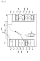
- FIG. 4A is a first diagram for illustrating an example of the parking support process of the present embodiment.
- an arrow represents a travel route when the vehicle is parked by automatic driving.
- a dotted circle represents the parking available space Me detected at the position P1.
- the control device 10 does not specify the parking space PR8 as the parking space Me.
- the parking space PL8 since the wall W serves as a barrier, it is not possible to secure an automatic driving route (corresponding to the dotted arrow in FIG. 4A), and the parking space PL8 is a parking space suitable for automatic driving. Absent. Therefore, the control device 10 does not specify the parking space PR8 as the parking space Me.
- the control device 10 Since there are parked vehicles in the parking spaces PR1, PR4, PR6, and PL3, the control device 10 does not identify the parking spaces PR1, PR4, PR6, and PL3 as the parking space Me. The control device 10 identifies the parking spaces PL1, PL2, PL4 to 7, PR2, PR3, PR5, and PR7 as the parking spaces Me.
- FIG. 4A the position of the traveling vehicle is P1, and the vehicle speed is V1.
- the control device 10 sets a range including PL2 to PL5 and PR2 to PR5 among the parking spaces included in the captured image at the position P1 of the host vehicle V as a detection range of the parking space Me.
- the detection range of the parking available space Me while the vehicle is traveling is not limited to the ranges of PL2 to PL5 and PR2 to PR5, and may be, for example, the ranges of PL1 to PL8 and PR1 to PR8.
- FIGS. 4B to 4D show the movement of the host vehicle V in time series, and the position of the host vehicle V is in the order of FIGS. 4A, 4B, 4C, and 4D. Move with. Note that the state of the host vehicle V shown in FIG. 4E described later is not included in the time series shown in FIGS. 4A to 4D.
- the recommended parking space Mr is detected in step S104.
- the recommended parking space Mr is a parking space suitable for parking the host vehicle V.
- the control device 10 detects the recommended parking space Mr according to the traveling state of the host vehicle from the detected plurality of parking spaces Me.
- the control device 10 calculates the travel route for parking in the parking space Me for each parking space Me.
- the calculated travel route is a route from the start position of the automatic driving to the position of the parking space Me.
- the control apparatus 10 specifies the start position of automatic driving
- the control device 10 sets a travel route for automatic driving with respect to the start position of automatic driving.
- the driving route for automatic driving is not necessarily limited to one, and the control device 10 sets an appropriate driving route according to the surrounding situation when performing automatic driving.
- the travel route until the host vehicle moves on the travel route from the start position of the automatic driving and reaches the position of the parking available space Me (parking completion position) becomes the calculation target route.
- the travel route differs for each parking space Me according to the number of turnovers, the travel distance, the maximum turning angle, and the like. Therefore, when the vehicle travels automatically along the travel route, the required parking time differs for each parking space Me. For example, the shorter the number of turnovers, the shorter the travel route distance, or the smaller the maximum turning angle, the shorter the required parking time.
- the distance from the vicinity of the parking space PL7 to the wall W is larger than the distance from the vicinity of the parking space PL6 to the wall W. short.
- the number of turn-backs when parking in the parking space PL7 is larger than the number of turn-backs when parking in the parking space PL6, and the parking time of the parking space PL7 is more than the parking time of the parking space PL6. become longer.
- the control device 10 calculates the gaze distance based on the vehicle speed of the host vehicle V.
- the gaze point distance corresponds to the distance from the position of the host vehicle V to the position where the driver of the host vehicle V is staring. The higher the vehicle speed, the farther the driver of the vehicle V looks. Therefore, the higher the vehicle speed, the longer the gazing point distance.
- the gazing point distance is the length of a straight line toward the front of the host vehicle V.
- the line corresponding to the gazing point distance is not necessarily a straight line, and may be a curved line.
- the curvature of the curve may be associated with the steering angle.
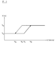
- FIG. 5 is a graph showing the relationship between the vehicle speed (V [km / s]) and the gaze point distance (Y [m]).
- the solid line indicates the characteristics when the vehicle speed increases, and the dotted line indicates the characteristics when the vehicle speed decreases.
- the gazing point distance is Ya.
- the gazing point distance changes at Ya until the vehicle speed changes from Va to Vc.
- the gazing point distance increases in proportion to the vehicle speed when the vehicle speed is in the range of Vc to Vd.
- the gaze point distance changes at Yb.
- the gazing point distance changes at Yb until the vehicle speed changes from Vd to Vb.
- the gazing point distance decreases in proportion to the decrease in the vehicle speed. That is, the characteristic indicating the relationship between the vehicle Va and the gaze point distance is a hysteresis characteristic between the increasing direction and decreasing direction of the vehicle speed Va.
- the ROM 12 of the control device 10 stores a relationship between the vehicle speed and the gaze point distance as a map.
- the control device 10 calculates a gaze point distance corresponding to the vehicle speed while referring to the map.
- FIG. 4B is a second diagram for illustrating an example of the parking support process of the present embodiment.
- the position of the traveling vehicle is P2, and the vehicle speed is V2.
- the control device 10 calculates a gaze point distance corresponding to the vehicle speed V2.
- the control device 10 specifies a position that is distant from the position P2 by the gazing point distance as the gazing point G2.
- the control device 10 gives an identification number to the parking space Me near the gazing point G2. For example, the numbers are assigned in the order closer to the gazing point G2.
- the control device 10 calculates the ease of entering the parking space Me.
- the index of ease of entering the parking space Me is the travel time for the host vehicle V to park in the parking space Me by automatic driving, and corresponds to the required parking time.
- the parking required time is a time when the vehicle travels by automatic driving along the travel route calculated for each parking space Me. Therefore, the ease of entering the parking space Me is determined by the travel distance, the number of operations (number of times of turning back), the maximum turning angle, the vehicle speed, and the like.
- the index of the ease of entering the parking space Me is not limited to the required parking time, and may include factors such as the certainty of parking in automatic driving, for example.
- the control apparatus 10 calculates the parking required time of the parking space Me for every parking space Me. In the example of FIG. 4B, the control device 10 calculates the required parking time of the parking spaces PL2, PL4, PL5, PR2, PR3, and PR5, respectively.
- the control device 10 compares the required parking time of each parking space Me with a predetermined required time threshold.
- the required time threshold value is a preset value, and is an upper limit value of the required time for parking in automatic driving. When the required parking time of the parking space Me is longer than the required time threshold, the control device 10 does not specify the parking space Me as the recommended parking space Mr.
- the control device 10 After identifying the parking available space Me whose parking required time is shorter than the required time threshold, the control device 10 sets, as the recommended parking available space Mr, the parking available space Me closest to the gazing point among the specified parking available spaces Me. To do.
- the control device 10 can recommend the parking space PL4. Set as space Mr.
- the parking available space Me having the shortest required parking time may be set as the recommended parking available space.
- step S105 the parking space Me and the recommended parking space Mr are presented.
- the control device 10 displays the set parking available space Me and the set recommended parking available space Mr on the display 21, thereby presenting the parking available space Me and the recommended parking available space Mr to the occupant.
- FIG. 6A is a first diagram for illustrating an example of a display screen in the parking support process of the present embodiment.
- the display screen in FIG. 6A is a display screen when the host vehicle V is traveling at the position P2 in FIG. 4B.
- the bird's-eye view image (top view) 21a displayed on the left side of the screen of the display 21 includes images (parking space boundaries) showing the parking spaces PL2 to PL5 and PR2 to PR5.
- an icon of the host vehicle V indicating the position of the host vehicle V is displayed in the center of the overhead image (top view) 21a.
- the monitoring image normal view
- a captured image of the camera 1a disposed on the front grill portion of the host vehicle V is displayed.
- a captured image of the camera 1d disposed near the rear bumper may be displayed.
- the image 21c is a message image.
- a circle indicating the parking space Me is displayed in the parking spaces PL2, PL4, PL5, PR2, PR3, PR5, and a dotted frame indicating the recommended parking space Mr is parked. It is displayed in the space PL4.
- a bird's-eye view image of a part of the car is displayed in the parking spaces PL3 and PR4.
- the passenger of the host vehicle can confirm the position of the parking space Me and the position of the recommended parking space Mr on the display screen of the display 21.
- the occupant can confirm from the message included in the image 21c that the vehicle is in the automatic driving mode and that the vehicle is requested to stop in order to perform automatic driving.
- the target parking space Mo is a parking space where the vehicle is parked by automatic driving, and represents a target location in automatic driving.
- the target parking space Mo is set based on an operation by the occupant. For example, when the display 21 is a touch panel display, the target parking space Mo is specified by the occupant touching a desired parking space portion, and information on the target parking space Mo is input to the control device 10. .
- step S107 If the target parking space Mo is input, the control flow proceeds to step S107. On the other hand, when the target parking space Mo is not input, the control flow returns to step S104, and the control flow from step S104 to step S106 is repeatedly executed.
- step S104 The control flow of the loop part from step S104 to step S106 will be described.
- the host vehicle V In the situation where the host vehicle V is traveling at the position P2 shown in FIG. 4B, when the target parking space Mo is not input, the host vehicle V is traveling, so the position of the gazing point moves forward. .
- FIG. 4C is a third diagram for illustrating an example of the parking support process of the present embodiment.
- the position of the gazing point moves from G2 to G3.
- the position of the gazing point becomes G3, the recommended parking space Mr moves from the parking space PL4 to the parking space PL5.
- FIG. 6B is a second diagram for illustrating an example of a display screen in the parking support process of the present embodiment.
- the display screen in FIG. 6B is a display screen when the host vehicle V is traveling at the position P3 in FIG. 4C.
- the frame indicating the recommended parking space Mr moves forward according to the movement of the host vehicle V on the display screen of the display 21. Then move to parking space PL5.
- the control device 10 sets the recommended parking space Mr for the parking space Me closest to the point of sight.
- the gazing point distance changes according to the vehicle speed of the host vehicle V.
- the characteristics of the gaze distance when the vehicle speed increases and the characteristics of the gaze distance when the vehicle speed decreases are not the hysteresis characteristics as shown in FIG. 5, but the characteristics shown by the solid line graph in FIG. The case will be described.
- the recommended parking space Mr set at the vehicle speed Vd is defined as a parking space PL5.
- the gazing point distance becomes shorter than Yb, so that the recommended parking space Mr moves from the parking space PL5 to PL4.
- the frame of the recommended parking space Mr is below the screen (the progress of the host vehicle) on the screen of the display 21. It moves so as to return to the direction opposite to the direction (the negative direction of the y-axis in FIG. 6A).
- hysteresis is given to the characteristic of the gaze distance with respect to the vehicle speed.
- the gaze point distance Yd is maintained. Therefore, the recommended parking space Mr stays at the position of the parking space PL5 or moves to the parking space PL6 on the vehicle traveling direction side of the position of the parking space PL5. Thereby, the unnatural movement of the recommended parking space Mr can be prevented.
- control device 10 performs the following control in order to suppress the movement in the left-right direction (the positive / negative direction of the x axis in FIG. 6A) in step S104.
- the control flow is executed.
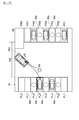
- FIG. 4E is a diagram for illustrating an example of the parking support process of the present embodiment.
- the recommended parking space Mr changes the position on the display screen of the display 21 according to the position of the host vehicle V.
- the host vehicle V is located between the left and right parking spaces PL1 to PL8 and the right parking spaces PR1 to 7 near the left and right centers (two points in FIG. 4E).
- FIG. 4E it is assumed that many parking spaces are vacant in the parking area.
- the position of the gazing point is a position on the left side of the center line.
- the position of the gazing point is on the right side of the center line. Therefore, when the host vehicle V travels along the direction in which the parking spaces are lined up, the position of the host vehicle V swings left and right across the center line, so the position of the gazing point also swings left and right. Since the parking available space Me closest to the gazing point is set as the recommended parking available space Mr, the display frame of the recommended parking available space Mr frequently moves from side to side. In the present embodiment, the following control is executed in order to prevent such hunting of the recommended parking space Mr on the display screen of the display 21.
- the control device 10 sets a display fixing mode for fixing the display area of the recommended parking space Mr according to the number of parking spaces Me.
- the display fixing mode an area that can be set as the recommended parking space Mr is fixed to either the left side or the right side.
- the control device 10 compares the number of parking spaces Me with a predetermined value. When the number of parking spaces Me is equal to or greater than a predetermined value, the control device 10 sets the display fixing mode.
- the control device 10 sets the settable area of the recommended parking space Mr to the left or right area according to the traveling state of the host vehicle. Specifically, the control device 10 calculates the distance from the parking space located on the side of the host vehicle to the host vehicle as the side distance (XL, XR). In the example of FIG. 4E, XL indicates the left side distance, and XR indicates the right side distance. The control device 10 compares XL and XR. When XL is shorter than XR, the control device 10 sets the left area as a settable area of the recommended parking space Mr. When XR is shorter than XL, the control device 10 sets the right area as the settable area of the recommended parking space Mr.
- the control device 10 After setting the settable area of the recommended parking space Mr to either one of the left and right, the control device 10 applies a bias in order to give hysteresis to the setting conditions when setting the left and right with respect to the length of the side distance.
- the length (W0 / 2) is a length obtained by halving the length of the side distance between the left parking space and the right parking space.
- the control device 10 compares the left side distance XL with the biased length (X HIS + W0 / 2).
- the control device 10 changes the settable area of the recommended parking space Mr from the left area to the right area.
- the control device 10 maintains the settable area of the recommended parking space Mr as the left area.
- the control device 10 compares the left side distance XL with the biased length (X HIS + W0 / 2). As shown in FIG. 4E, when the left side distance XL is equal to or shorter than the length (X HIS + W0 / 2), the control device 10 sets the settable area of the recommended parking space Mr as the left area. To keep in the state. On the other hand, when the vehicle moves to the right side and the right side distance XR is longer than the length (X HIS + W0 / 2), the control device 10 changes the settable area of the recommended parking space Mr from the left area. Change to the right area.
- the left / right selection when setting as the settable region has a hysteresis characteristic with respect to the position in the lateral direction of the host vehicle.
- the recommended parking space Mr is displayed with priority over the left area compared to the right area.
- the control device 10 sets the recommended parking space Mr without setting the display fixing mode.
- the empty parking spaces are quickly presented to the occupant rather than preventing hunting. Thereby, the convenience of the system can be enhanced for the occupant.
- FIG. 6C is a third diagram illustrating an example of a display screen in the parking assistance process of the present embodiment.
- the display screen in FIG. 6C is a display screen when the host vehicle V stops at the position P3 in FIG. 4C.
- the user can confirm that the selection and input of the target parking space Mo are requested from the message included in the image 21c.
- step S107 the target parking space Mo is set and the target parking space Mo is presented.
- the recommended parking space Mr is displayed at the position of the parking space PL5.
- the control device 10 sets the parking space PL5 as the target parking space Mo.
- FIG. 4D is a fourth diagram for illustrating an example of the parking support process of the present embodiment.
- FIG. 6D is a fourth diagram illustrating an example of a display screen in the parking assistance process of the present embodiment.
- the display screen in FIG. 6D is a display screen when the host vehicle stops at the position P4 in FIG. 4D.
- the control device 10 presents the target parking space Mo to the occupant by displaying a display screen as shown in FIG. 6D on the display 21. The occupant can confirm from the message included in the image 21c that automatic driving can be started.
- step S108 the control device 10 calculates a travel route for moving the host vehicle to the target parking space Mo.
- the user designates the parking space PL5 presented as the recommended parking space Mr as the target parking space Mo.
- the user designates this parking space as the target parking space Mo by touching the parking space PL5 displayed on the touch panel display 21.
- the target parking space Mo is determined by this operation.
- the host vehicle V moves to a position P4 next to the target parking space PL5 (Mo). This position P4 becomes the automatic parking start position of the host vehicle.
- the control device 10 calculates a travel route based on the positional relationship between the stop position P4 of the host vehicle V that starts the parking operation (movement) and the position of the target parking space Mo. Although not particularly limited, the control device 10 calculates, as travel routes, a stop position of the host vehicle V, that is, a curve from the parking assistance start position to the return position P5 and a curve from the return position P5 to the target parking space Mo. To do. The control device 10 calculates travel routes corresponding to each of the parallel parking (A), the parallel parking (B), and the diagonal parking (C) shown in FIG. In the present embodiment, the travel route is calculated. However, the present invention is not limited to this.
- the travel route according to the type of the parking space is stored in a memory (ROM), and the travel route is determined when parking is started. You may make it read from memory.
- the parking mode (parallel parking, parallel parking, diagonal parking, etc.) may be selected by the user of the host vehicle V.
- the control device 10 reads the travel route corresponding to the selected parking mode, and calculates the travel route based on the relationship between the position of the host vehicle V and the position of the target parking space Mo when the automatic parking process is started.
- the control device 10 causes the vehicle controller 30 to execute a process of moving the host vehicle to the target parking space Mo along the calculated travel route.
- step S109 the parking support apparatus 100 according to the present embodiment executes a parking support process or an automatic parking process.
- the parking assistance apparatus 100 controls the operation of the drive system 40 via the vehicle controller 30 so that the host vehicle moves along the travel route.
- FIG. 6E is a fifth diagram for illustrating an example of a display screen in the parking support process of the present embodiment.
- the display screen of the display 21 becomes a screen as shown in FIG. 6E, and the host vehicle V moves forward.
- a message is displayed on the image 21c informing that the host vehicle V is moving forward by automatic driving and that the occupant is gazing around the host vehicle V.
- automatic driving control of the parking assistance apparatus 100 will be described.
- the parking assist device 100 feeds the output value of the steering angle sensor 50 included in the steering device to the driving system 40 of the own vehicle such as an EPS motor so that the movement locus of the own vehicle V matches the calculated travel route.
- the command signal is calculated and sent to the drive system 40 or the vehicle controller 30 that controls the drive system 40.
- the parking support device 100 of this embodiment includes a parking support control unit.
- the parking assistance control unit acquires shift range information from the AT / CVT control unit, wheel speed information from the ABS control unit, rudder angle information from the rudder angle control unit, engine speed information from the ECM, and the like. Based on these, the parking assist control unit calculates and outputs instruction information related to automatic steering to the EPS control unit, instruction information such as a warning to the meter control unit, and the like.
- the control device 10 acquires, via the vehicle controller 30, each piece of information acquired by the steering angle sensor 50, the vehicle speed sensor 60, and other sensors included in the vehicle steering device.
- the drive system 40 of the present embodiment parks the host vehicle V in the target parking space Mo by driving based on the control command signal acquired from the parking assist device 100.
- the steering device of the present embodiment is a drive mechanism that moves the host vehicle V in the left-right direction.
- the EPS motor included in the drive system 40 drives the power steering mechanism included in the steering device based on the control command signal acquired from the parking assist device 100 to control the steering amount, and moves the host vehicle V to the target parking space Mo. Support the operation when you do.
- movement technique of parking assistance are not specifically limited, The technique known at the time of application can be applied suitably.
- the parking assist device 100 targets the parking of the host vehicle V along the travel route calculated based on the movement start position P3 of the host vehicle V and the position of the target parking space Mo.
- the accelerator / brake operation is automatically controlled based on the designated control vehicle speed (set vehicle speed), and the steering operation of the steering device is automatically controlled according to the vehicle speed. . That is, at the time of parking assistance according to the present embodiment, the steering operation of the steering device and the accelerator / brake operation are automatically performed. Without boarding the vehicle, it is also possible to perform parking processing by remote control that performs parking by transmitting a setting command for the target parking space Mo, a parking processing start command, a parking interruption command, or the like to the vehicle from the outside.
- the parking assistance device 100 controls the drive system 40 based on the preset vehicle speed calculated in advance so that the host vehicle V moves along the travel routes G2 and G3, and the preset steering angle calculated in advance.
- the vehicle steering device is controlled based on the above.
- the above is the basic control content of the parking assistance apparatus 100 of the present embodiment.
- FIG. 8 is a plan view showing a state of the host vehicle V when the parking space Me is detected.
- the control device 10 selects a parking space Me from the parking space PLn. To detect.
- the function of executing the detection process of the parking space Me included in the control device 10 includes a function of executing a frame line detection process, a parking space detection process, and an empty / parking determination process.
- the frame line detection process as described above, the frame line is detected based on the overhead image generated by the image processing device 2. Further, in the parking space detection process, the parking space PLn defined by the frame line detected in the frame line detection process is detected.
- the length of the frame line on the back side of the parking space PL2 to be discriminated is measured, and discriminated based on the length of the frame line on the back side.
- This method is based on the premise that a frame line on the back side of the parking space PL2 to be discriminated is detected.
- it may be difficult to detect the frame line for example, the parking space next to the parking space PL2 to be discriminated (hereinafter referred to as the parking space PL1 on the near side and the parking space PL3 on the back side).
- the shadow of the parked vehicle overlaps the frame line of the parking space PL2 to be discriminated, so that a situation in which the back frame line is not detected may occur.
- the empty vehicle / parking detection process detects the parking status of the parking space using the parking status detection device according to the present invention.
- the parking state detection device used in the empty vehicle / parking detection process is a distance measuring sensor such as a camera, a radar, or a sonar, and may be any device that detects the length of an object.
- the parking state of the parking space is determined from the parking state information acquired by the parking state detection device.
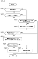
- FIG. 9 is a flowchart showing the procedure of the detection process of the parking space Me executed by the control device 10.
- the processing routine shown in this flowchart is executed in a parking lot, and is executed every predetermined cycle (for example, every 10 msec).
- step S201 the control device 10 determines whether or not the far and near frame lines of the parking space PL2 to be discriminated are detected. If it is determined in step S201 that the back and front frame lines have been detected, the process proceeds to step S202. If it is determined in step S201 that the back and front frame lines have not been detected, The process proceeds to step S203.
- step S202 the control device 10 determines whether or not the parking space PL2 to be determined has been detected based on the detected positions and angles of the far side and near side frame lines. If it is determined in step S202 that the determination target parking space PL2 has been detected, the process proceeds to step S205. If it is determined in step S202 that the determination target parking space PL2 has not been detected, the process proceeds to step S203. move on.
- step S203 the control device 10 determines whether or not the width of the parking space PL2 to be determined is greater than or equal to W1.
- a method of setting the predetermined width W1 for example, a method of setting the width of the parking space PLn closer to the traveling direction than the parking space PL2 to be determined to the predetermined width W1 can be exemplified.
- the predetermined width W1 may be acquired and set by an external server, road-to-vehicle communication, or vehicle-to-vehicle communication, or may be set based on the size of the vehicle, and may vary depending on the vehicle. May be set.
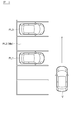
- the distance between the parked vehicle existing in the parking space PL1 adjacent to the front side and the parked vehicle existing in the parking space PL3 adjacent to the back side is equal to or greater than the predetermined width W1.
- the distance between the parked vehicle in the parking space PL3 adjacent to the back side and the frame line on the near side of the parking space PL2 to be determined is equal to or greater than a predetermined width W1.
- step S203 If it is determined in step S203 that the width of the parking space PL2 to be determined is equal to or greater than the predetermined width W1, the process proceeds to step S204. On the other hand, when it is determined in step S203 that the width of the parking space PL2 to be determined is less than the predetermined width W1, the processing routine is terminated.
- step S204 the control device 10 sets a determination target parking space PL2 having a predetermined width W1. Then, the process proceeds to step S205.
- step S205 the control device 10 determines whether there is a parked vehicle in the parking space PL3 adjacent to the back side.
- the parking state of the parking space PL2 to be determined is determined using the parked vehicle in the parking space PL3 adjacent to the back side. It is determined by the step whether or not the parking status of the determination target parking space PL2 can be determined. And when a parked vehicle exists in parking space PL3 on the back side, it progresses to step S206. If not, the processing routine is terminated.
- step S206 the control device 10 measures the length L1 of the side surface of the parked vehicle in the parking space PL3 adjacent to the back side (the surface located on the side of the discrimination target parking space PL2).
- the measurement of the vehicle side length L1 in the present embodiment is performed by analyzing the captured image of the camera 1.
- this length L1 is not the actual distance of the length of the vehicle side surface but the length of the vehicle side surface displayed in the captured image of the camera 1.
- the actual distance of the length of a vehicle side surface may be sufficient.
- a sonar or a radar may be used.
- step S207 the control device 10 determines whether or not the length L1 of the side surface of the parked vehicle in the parking space PL3 adjacent to the back side measured in step S206 is equal to or greater than a predetermined value L0.
- This predetermined value L0 will be described later.
- step S208 when the length L1 satisfies the condition that the length L1 is equal to or greater than the predetermined value L0, the control device 10 determines the parking space PL2 to be determined as an empty state.
- step S209 when the length L1 does not satisfy the condition of the predetermined value L0 or more, the control device 10 determines the parking space PL2 to be determined as a parking state.
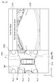
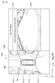
- FIG. 10 and FIG. 11 a situation in which parking vehicles exist in the parking space PL3 on the back side and the parking space PL1 on the near side will be examined.
- FIG. 10 in the situation, when there is no parked vehicle in the parking space PL2 to be discriminated, the entire front side portion and the rear side portion of the side of the parked vehicle in the parking space PL3 adjacent to the back side are displayed. Appear in the imaging range of the camera 1.
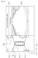
- FIG. 11 in the situation, when there is a parked vehicle in the parking space PL2 to be discriminated, the entire rear side portion of the side surface of the parked vehicle in the parking space PL3 adjacent to the back side is discriminated. It hides behind the parked vehicle in the target parking space PL2 and does not appear in the imaging range of the camera 1.
- the parking space to be determined PL2 is determined as an empty state.
- the predetermined value L0 is set to, for example, about 1 ⁇ 2 of the average vehicle length or about 1 ⁇ 2 of the length of the frame line.
- the predetermined value L0 may be set according to the angle between the host vehicle V and the parking space PL2 to be determined. That is, the predetermined value L0 may be set larger as the angle between the host vehicle V and the parking space to be determined increases.
- the predetermined value L0 may be a fixed value or a variable value.
- the predetermined value L0 may be determined according to the positional relationship between the parking space PL2 to be determined and the host vehicle, or may be variable during traveling.
- the distance is decreased as the distance between the parking space PL2 to be determined and the host vehicle V increases.
- the parking system with an angle has the same result as the parallel parking system. That is, as shown in FIG. 12, in the situation where there is a parked vehicle in the parking space PL3 adjacent to the back side, the back side that appears in the imaging range of the camera 1 when the parking space PL2 to be discriminated is empty.
- the length L1 of the side surface of the parked vehicle in the adjacent parking space PL3 is longer than the predetermined value L0.
- the length L1 is shorter than the predetermined value L0.
- the length of the side surface of the parked vehicle in the parking space PL3 adjacent to the back side displayed in the captured image of the camera 1 is the same regardless of the direction before and after parking. Is also applicable to forward-facing parking.
- the same result is obtained for the parallel parking method as for the parallel parking method. That is, as shown in FIG. 14, in the situation where there is a parked vehicle in the parking space PL3 adjacent to the back side, the back side that appears in the imaging range of the camera 1 when the parking space PL2 to be discriminated is empty.
- the length L1 of the rear surface of the parked vehicle in the adjacent parking space PL3 is a predetermined value L0 (for example, about 1/2 of the vehicle width of the average vehicle or a frame line) Longer than about 1/2 of the length of
- L0 for example, about 1/2 of the vehicle width of the average vehicle or a frame line
- the length L1 is shorter than the predetermined value L0.
- the control device 10 determines that the measured length L1 of the side surface of the parked vehicle in the parking space PL3 adjacent to the back side and the average vehicle length 1 When the measured length L1 satisfies the condition that the measured length L1 is equal to or greater than the predetermined value L0 by comparing with a predetermined value L0 such as about / 2, the determination target parking space PL2 is determined to be an empty vehicle state and the condition is not satisfied In addition, the determination target parking space PL2 is determined as a parking state.
- the control device 10 determines that the measured length L1 of the rear surface of the parked vehicle in the parking space PL3 adjacent to the back side and the average vehicle width 1 When the measured length L1 satisfies the condition that the measured length L1 is equal to or greater than the predetermined value L0 by comparing with a predetermined value L0 such as about / 2, the determination target parking space PL2 is determined to be an empty vehicle state and the condition is not satisfied In addition, the determination target parking space PL2 is determined as a parking state.
- the parking space to be determined It is possible to accurately determine the empty / parking of PL2.
- the control device 10 determines whether or not there is a parking space having a predetermined width W1 or more of the parking space PLn on the near side adjacent to the near side of the parking space PL3 on the back side. And when the said parking space exists, the said parking space is set to the parking space PL2 of the discrimination
- 16 and 17 are diagrams illustrating captured images of the camera 1.
- a situation is shown in which the determination target parking space PL2 is in an empty state, and there are parked vehicles in the rear side adjacent parking space PL3 and the front side adjacent parking space PL1.
- the side surface of the parked vehicle in the parking space PL3 adjacent to the back side appears in the imaging range of the camera 1.
- the rear wheel 4, the headlamp 5, and the reflector 6 existing in the rear part of the side surface of the parked vehicle in the parking space PL 3 adjacent to the back side appear in the imaging range of the camera 1.
- FIG. 18 is a flowchart showing the procedure of the second embodiment of the detection process of the parking space Me that is executed by the control device 10.
- the processing routine shown in this flowchart is started when a parked vehicle existing in the detected parking space PLn is detected.
- repeated description is abbreviate
- step S305 the control device 10 analyzes the image of the side surface of the parked vehicle in the parking space PL3 adjacent to the back side.
- the side surface of the parked vehicle is extracted from the captured image of the camera 1 by a known method such as pattern matching, and a predetermined feature existing in the rear portion of the side surface is extracted from the extracted image of the side surface of the parked vehicle. (For example, the rear wheel 4, the headlight 5, the reflector 6, etc.) are extracted.
- a predetermined feature existing in the rear side portion of the side surface of the parked vehicle is extracted, but the parking space PL3 adjacent to the back side is extracted.
- predetermined features for example, a front wheel, a headlight, etc.
- a predetermined feature existing in the rear part or the front part of the side surface of the parked vehicle in the parking space PL3 adjacent to the back side is extracted.
- a predetermined feature for example, a left rear tire
- a predetermined feature for example, a right rear tire
- a method for extracting a reflection object having a luminance value equal to or higher than a predetermined value can be exemplified in addition to pattern matching.
- the rear wheel or front wheel can be extracted by extracting two wheels that are aligned along the longitudinal direction of the parking space (forward and backward direction) by pattern matching, etc.
- inner side of the longitudinal direction of a parking space among these wheels can be illustrated.
- the parallel parking method as a method of extracting one of the left and right tires, two tires arranged along the width direction of the parking space are extracted by pattern matching or the like, and parking is performed out of the extracted two tires.
- a method for extracting a tire located on the far side in the width direction of the space can be exemplified.
- step S306 the control device 10 determines whether or not the predetermined feature is detected in step S305.
- step S307 when it is determined that the predetermined feature has been detected, the control device 10 determines that the parking space PL2 to be determined is an empty state. On the other hand, when determining in step 308 that the predetermined feature has not been detected, the control device 10 determines the parking space PL2 to be determined as a parking state.
- the control device 10 in the case of the parallel parking system, has a rear side portion of the side of the vehicle parked rearward of the parking space PL3 adjacent to the back side or the parking space PL3 adjacent to the back side. It is determined whether or not a predetermined feature such as a wheel is present in the front portion of the side surface of the vehicle parked forward. Then, when the predetermined feature is present, the control device 10 determines that the determination target parking space PL2 is in an empty state, and when the predetermined feature does not exist, parks the determination target parking space PL2. Judged as a state.
- the control device 10 when the parking space of the parallel parking system is located on the left side of the traveling path of the vehicle, the control device 10 is arranged on the left side of the rear part of the parked vehicle in the parking space on the back side. It is determined whether or not a predetermined feature such as a tire exists. When the predetermined feature is present, the control device 10 determines the determination target parking space as an empty state, and when the predetermined feature does not exist, the control device 10 sets the determination target parking space as an empty state. Determine. Further, in the present embodiment, when the parallel parking system parking space is located on the right side of the traveling path of the vehicle, the control device 10 is placed on the right side of the rear portion of the parked vehicle in the parking space adjacent to the back side.
- control device 10 determines whether or not a predetermined feature such as a tire exists.
- the control device 10 determines the determination target parking space as an empty state, and when the predetermined feature does not exist, the control device 10 sets the determination target parking space as an empty state. Determine.
- the parking space to be determined It is possible to accurately determine the empty / parking of PL2.
- control device 10 in the above-described embodiment corresponds to an example of the “parked vehicle detection unit”, “measurement unit”, and “parking space detection unit” in the present invention. Further, the “camera 1” and the “ranging device 3” in the above-described embodiment correspond to an example of the parking state detection device of the present invention.
- the length of the side surface of the parked vehicle in the parking space PL3 on the back side is detected from the captured image of the camera 1 or a predetermined feature of the parked vehicle is extracted. This is not essential. Based on the distance measurement signal of the distance measuring device 3, the length of the side surface of the parked vehicle in the parking space PL3 adjacent to the back side may be detected, or a predetermined feature of the parked vehicle may be extracted.
- This embodiment is a fixed camera with which the parking lot was equipped, the camera of other vehicles, a user's carrying It may be based on a camera.
- the parking space information may be acquired from the outside and the parking state of the parking space may be grasped.
Landscapes
- Engineering & Computer Science (AREA)
- Physics & Mathematics (AREA)
- General Physics & Mathematics (AREA)
- Mechanical Engineering (AREA)
- Transportation (AREA)
- Theoretical Computer Science (AREA)
- Multimedia (AREA)
- Chemical & Material Sciences (AREA)
- Combustion & Propulsion (AREA)
- Automation & Control Theory (AREA)
- Geometry (AREA)
- Computer Vision & Pattern Recognition (AREA)
- Traffic Control Systems (AREA)
- Control Of Driving Devices And Active Controlling Of Vehicle (AREA)
- Image Analysis (AREA)
Abstract
Description
3 測距装置
10 制御装置
Claims (5)
- 駐車場の状況を検知する駐車状況検知装置により取得された駐車状況情報から空車状態の駐車スペースを検出する駐車スペース検出方法であって、
空車を判別する判別対象の駐車スペースの隣で前記駐車状況検知装置から遠い側の駐車スペースに存在する駐車車両を検出し、
前記駐車車両の前記判別対象の駐車スペース側に位置する面における横方向の長さを測定し、
前記横方向の長さが所定値以上である場合に、前記判別対象の駐車スペースを空車状態の駐車スペースとして検出する駐車スペース検出方法。 - 駐車場の状況を検知する駐車状況検知装置により取得された駐車状況情報から空車状態の駐車スペースを検出する駐車スペース検出方法であって、
空車を判別する判別対象の駐車スペースの隣で前記駐車状況検知装置から遠い側の駐車スペースに存在する駐車車両を検出し、
前記駐車車両の前記判別対象の駐車スペース側に位置する面における左右の領域のうち、前記駐車状況検知装置から遠い側の領域から、所定の特徴物が検出される場合に、前記判別対象の駐車スペースを空車状態の駐車スペースとして検出する駐車スペース検出方法。 - 駐車スペースの幅を取得し、
取得した幅が所定幅以上の場合に、当該駐車スペースを前記判別対象の駐車スペースとして検出する請求項1又は2に記載の駐車スペース検出方法。 - 駐車場の状況を検知する駐車状況検知装置により取得された駐車状況情報から空車状態の駐車スペースを検出する駐車スペース検出装置であって、
空車を判別する判別対象の駐車スペースの隣で前記駐車状況検知装置から遠い側の駐車スペースに存在する駐車車両を検出する駐車車両検出部と、
前記駐車車両の前記判別対象の駐車スペース側に位置する面における横方向の長さを測定する測定部と、
前記横方向の長さが所定値以上である場合に、前記判別対象の駐車スペースを空車状態の駐車スペースとして検出する駐車スペース検出部と
を備える駐車スペース検出装置。 - 駐車場の状況を検知する駐車状況検知装置により取得された駐車状況情報から空車状態の駐車スペースを検出する駐車スペース検出装置であって、
空車を判別する判別対象の駐車スペースの隣で前記駐車状況検知装置から遠い側の駐車スペースに存在する駐車車両を検出する駐車車両検出部と、
前記駐車車両の前記判別対象の駐車スペース側に位置する面における左右の領域のうち、前記駐車状況検知装置から遠い側の領域から、所定の特徴物が検出される場合に、前記判別対象の駐車スペースを空車状態の駐車スペースとして検出する駐車スペース検出部と
を備える駐車スペース検出装置。
Priority Applications (11)
| Application Number | Priority Date | Filing Date | Title |
|---|---|---|---|
| JP2017546357A JP6531832B2 (ja) | 2015-10-22 | 2015-10-22 | 駐車スペース検出方法および装置 |
| RU2018118333A RU2700635C1 (ru) | 2015-10-22 | 2015-10-22 | Способ и устройство обнаружения мест для парковки |
| CN201580083940.4A CN108136987B (zh) | 2015-10-22 | 2015-10-22 | 停车位检测方法及装置 |
| MX2018004709A MX367250B (es) | 2015-10-22 | 2015-10-22 | Método y dispositivo de detección de espacio de estacionamiento. |
| CA3002641A CA3002641C (en) | 2015-10-22 | 2015-10-22 | Parking space detection method and device |
| EP15906707.3A EP3366524B1 (en) | 2015-10-22 | 2015-10-22 | Parking space detection method and device |
| PCT/JP2015/079895 WO2017068701A1 (ja) | 2015-10-22 | 2015-10-22 | 駐車スペース検出方法および装置 |
| KR1020187013827A KR102042371B1 (ko) | 2015-10-22 | 2015-10-22 | 주차 스페이스 검출 방법 및 장치 |
| US15/769,292 US10163016B2 (en) | 2015-10-22 | 2015-10-22 | Parking space detection method and device |
| BR112018008126-4A BR112018008126B1 (pt) | 2015-10-22 | 2015-10-22 | Método e dispositivo de detecção de espaço de estacionamento |
| MYPI2018701520A MY191078A (en) | 2015-10-22 | 2015-10-22 | Parking space detection method and device |
Applications Claiming Priority (1)
| Application Number | Priority Date | Filing Date | Title |
|---|---|---|---|
| PCT/JP2015/079895 WO2017068701A1 (ja) | 2015-10-22 | 2015-10-22 | 駐車スペース検出方法および装置 |
Publications (1)
| Publication Number | Publication Date |
|---|---|
| WO2017068701A1 true WO2017068701A1 (ja) | 2017-04-27 |
Family
ID=58557087
Family Applications (1)
| Application Number | Title | Priority Date | Filing Date |
|---|---|---|---|
| PCT/JP2015/079895 WO2017068701A1 (ja) | 2015-10-22 | 2015-10-22 | 駐車スペース検出方法および装置 |
Country Status (11)
| Country | Link |
|---|---|
| US (1) | US10163016B2 (ja) |
| EP (1) | EP3366524B1 (ja) |
| JP (1) | JP6531832B2 (ja) |
| KR (1) | KR102042371B1 (ja) |
| CN (1) | CN108136987B (ja) |
| BR (1) | BR112018008126B1 (ja) |
| CA (1) | CA3002641C (ja) |
| MX (1) | MX367250B (ja) |
| MY (1) | MY191078A (ja) |
| RU (1) | RU2700635C1 (ja) |
| WO (1) | WO2017068701A1 (ja) |
Cited By (11)
| Publication number | Priority date | Publication date | Assignee | Title |
|---|---|---|---|---|
| WO2019008760A1 (ja) * | 2017-07-07 | 2019-01-10 | 日産自動車株式会社 | 駐車支援方法及び駐車支援装置 |
| WO2019008762A1 (ja) * | 2017-07-07 | 2019-01-10 | 日産自動車株式会社 | 駐車支援方法及び駐車支援装置 |
| WO2019008764A1 (ja) * | 2017-07-07 | 2019-01-10 | 日産自動車株式会社 | 駐車支援方法及び駐車支援装置 |
| JP6479231B1 (ja) * | 2018-02-28 | 2019-03-06 | 三菱電機株式会社 | 駐車支援装置および駐車支援方法 |
| CN110869245A (zh) * | 2017-07-07 | 2020-03-06 | 日产自动车株式会社 | 泊车辅助方法以及泊车辅助装置 |
| JP2021026625A (ja) * | 2019-08-07 | 2021-02-22 | アイシン精機株式会社 | 特定領域検知装置 |
| JP2021163452A (ja) * | 2020-03-30 | 2021-10-11 | デンソー インターナショナル アメリカ インコーポレーテッド | 汎用ナビゲーションシステムを有する車両のための目標指向型ナビゲーションシステム、方法、および非一時的コンピュータ可読媒体 |
| CN113516867A (zh) * | 2020-04-10 | 2021-10-19 | 奥迪股份公司 | 停车指示装置、停车辅助系统、停车管理系统和相应方法 |
| US11498553B2 (en) * | 2019-06-24 | 2022-11-15 | Honda Motor Co., Ltd. | Parking assist system |
| JP7466324B2 (ja) | 2020-02-12 | 2024-04-12 | フォルシアクラリオン・エレクトロニクス株式会社 | 画像処理装置及び画像処理方法 |
| DE112022003723T5 (de) | 2021-07-27 | 2024-05-08 | Sony Semiconductor Solutions Corporation | Informationsverarbeitungsvorrichtung, informationsverarbeitungsverfahren und programm |
Families Citing this family (29)
| Publication number | Priority date | Publication date | Assignee | Title |
|---|---|---|---|---|
| WO2018226600A1 (en) | 2017-06-05 | 2018-12-13 | Citifyd, Inc. | Parking objects detection system |
| KR102429494B1 (ko) * | 2017-10-13 | 2022-08-05 | 현대자동차주식회사 | 차량의 목표주차공간 표시 장치 및 그 방법 |
| DE102017218921B4 (de) * | 2017-10-24 | 2024-05-23 | Bayerische Motoren Werke Aktiengesellschaft | Verfahren, Vorrichtung, Computerprogramm und Computerprogrammprodukt zum Betreiben einer Displayeinheit eines Fahrzeugs |
| JP7089355B2 (ja) * | 2017-11-13 | 2022-06-22 | キヤノン株式会社 | 画像処理装置、画像処理装置の制御方法及びプログラム |
| KR102077573B1 (ko) * | 2018-01-31 | 2020-02-17 | 엘지전자 주식회사 | 자동 주차 시스템 및 차량 |
| DE102018205968A1 (de) * | 2018-04-19 | 2019-10-24 | Volkswagen Aktiengesellschaft | Verfahren zum Betreiben eines Parkassistenzsystems eines Kraftfahrzeugs und Parkassistenzsystem für ein Kraftfahrzeug |
| US11475769B2 (en) | 2018-07-09 | 2022-10-18 | Mitsubishi Electric Corporation | Parking assistance apparatus and parking assistance method |
| FR3084628B1 (fr) * | 2018-07-31 | 2021-06-11 | Renault Sas | Procede de determination d'un type d'emplacement de stationnement |
| CN110795974B (zh) * | 2018-08-03 | 2023-04-07 | 中国移动通信有限公司研究院 | 一种图像处理方法、装置、介质和设备 |
| JP7026817B2 (ja) * | 2018-10-03 | 2022-02-28 | 三菱電機株式会社 | 駐車支援装置および駐車支援方法 |
| US10733891B2 (en) * | 2018-11-05 | 2020-08-04 | Toyota Motor Engineering & Manufacturing North America, Inc. | Parking lot assistant |
| KR102653169B1 (ko) * | 2018-12-12 | 2024-04-03 | 주식회사 에이치엘클레무브 | 후측방 경보 제어 장치 및 방법 |
| JP7203587B2 (ja) * | 2018-12-14 | 2023-01-13 | 株式会社デンソーテン | 画像処理装置および画像処理方法 |
| CN110796889A (zh) * | 2019-01-25 | 2020-02-14 | 长城汽车股份有限公司 | 用于代客泊车的车位确定方法及装置 |
| CN109677398A (zh) * | 2019-02-22 | 2019-04-26 | 海马汽车有限公司 | 自动泊车方法、装置及汽车 |
| KR20200130883A (ko) | 2019-04-26 | 2020-11-23 | 현대모비스 주식회사 | 주차 지원 장치 및 방법 |
| JP7065068B2 (ja) * | 2019-12-13 | 2022-05-11 | 本田技研工業株式会社 | 車両周囲監視装置、車両、車両周囲監視方法およびプログラム |
| JP6966529B2 (ja) * | 2019-12-13 | 2021-11-17 | 本田技研工業株式会社 | 駐車支援装置、駐車支援方法、および、プログラム |
| US10916141B1 (en) | 2019-12-18 | 2021-02-09 | Toyota Motor Engineering & Manufacturing North America, Inc. | System and method for generating a parking space directory |
| US11335199B2 (en) * | 2020-04-14 | 2022-05-17 | Saudi Arabian Oil Company | Parking control system, parking control method, and mobile robot device |
| JP2021180382A (ja) * | 2020-05-12 | 2021-11-18 | フォルシアクラリオン・エレクトロニクス株式会社 | 画像処理装置及び画像処理方法 |
| JP2021191658A (ja) * | 2020-06-05 | 2021-12-16 | パナソニックIpマネジメント株式会社 | 運転支援装置、運転支援方法、及び、運転支援プログラム |
| CN112349133B (zh) * | 2020-07-20 | 2022-11-04 | 北京筑梦园科技有限公司 | 一种不规范停车的管理方法、服务器及停车管理系统 |
| CN112364884B (zh) * | 2020-10-09 | 2024-02-20 | 江苏星闪世图科技(集团)有限公司 | 一种移动物体侦测的方法 |
| CN112669615B (zh) * | 2020-12-09 | 2023-04-25 | 上汽大众汽车有限公司 | 一种基于摄像头的停车位检测方法和系统 |
| CN112927552B (zh) * | 2021-01-20 | 2022-03-11 | 广州小鹏自动驾驶科技有限公司 | 一种车位检测的方法和装置 |
| CN113251962B (zh) * | 2021-03-29 | 2022-07-05 | 英博超算(南京)科技有限公司 | 基于机器学习的超声波车位补偿系统 |
| CN114530056B (zh) * | 2022-02-15 | 2023-05-02 | 超级视线科技有限公司 | 一种基于定位信息和图像信息的停车管理方法及系统 |
| CN114882701B (zh) * | 2022-04-28 | 2023-01-24 | 上海高德威智能交通系统有限公司 | 车位检测方法、装置、电子设备及机器可读存储介质 |
Citations (2)
| Publication number | Priority date | Publication date | Assignee | Title |
|---|---|---|---|---|
| JP2010198440A (ja) * | 2009-02-26 | 2010-09-09 | Nissan Motor Co Ltd | 駐車支援装置及び障害物検知方法 |
| WO2016002405A1 (ja) * | 2014-07-04 | 2016-01-07 | クラリオン株式会社 | 駐車枠認識装置 |
Family Cites Families (12)
| Publication number | Priority date | Publication date | Assignee | Title |
|---|---|---|---|---|
| JP2001202596A (ja) * | 2000-01-18 | 2001-07-27 | Sumitomo Densetsu Corp | 駐車検出装置 |
| JP2007030700A (ja) * | 2005-07-27 | 2007-02-08 | Aisin Seiki Co Ltd | 駐車支援装置 |
| JP5440867B2 (ja) | 2010-06-18 | 2014-03-12 | アイシン精機株式会社 | 駐車支援装置 |
| JP2012017021A (ja) * | 2010-07-08 | 2012-01-26 | Panasonic Corp | 駐車支援装置および車両 |
| JP5212748B2 (ja) * | 2010-09-29 | 2013-06-19 | アイシン精機株式会社 | 駐車支援装置 |
| DE102010051206A1 (de) * | 2010-11-12 | 2012-05-16 | Valeo Schalter Und Sensoren Gmbh | Verfahren zum Erzeugen eines Bilds einer Fahrzeugumgebung und Abbildungsvorrichtung |
| JP6015314B2 (ja) * | 2012-09-28 | 2016-10-26 | アイシン精機株式会社 | 駐車目標位置を算出する装置、駐車目標位置を算出する方法およびプログラム |
| WO2014083824A1 (ja) * | 2012-11-27 | 2014-06-05 | 日産自動車株式会社 | 車両用加速抑制装置及び車両用加速抑制方法 |
| US8923565B1 (en) * | 2013-09-26 | 2014-12-30 | Chengdu Haicun Ip Technology Llc | Parked vehicle detection based on edge detection |
| US20150310745A1 (en) * | 2014-04-24 | 2015-10-29 | The Taubman Company LLC | Method and apparatus for locating vacant parking locations in a parking lot or structure |
| US9773413B1 (en) * | 2014-09-16 | 2017-09-26 | Knighscope, Inc. | Autonomous parking monitor |
| JP6503218B2 (ja) * | 2015-04-03 | 2019-04-17 | 株式会社日立製作所 | 運転支援システム、運転支援装置及び運転支援方法 |
-
2015
- 2015-10-22 RU RU2018118333A patent/RU2700635C1/ru active
- 2015-10-22 WO PCT/JP2015/079895 patent/WO2017068701A1/ja active Application Filing
- 2015-10-22 CN CN201580083940.4A patent/CN108136987B/zh active Active
- 2015-10-22 MY MYPI2018701520A patent/MY191078A/en unknown
- 2015-10-22 US US15/769,292 patent/US10163016B2/en active Active
- 2015-10-22 MX MX2018004709A patent/MX367250B/es active IP Right Grant
- 2015-10-22 CA CA3002641A patent/CA3002641C/en active Active
- 2015-10-22 KR KR1020187013827A patent/KR102042371B1/ko active IP Right Grant
- 2015-10-22 JP JP2017546357A patent/JP6531832B2/ja active Active
- 2015-10-22 BR BR112018008126-4A patent/BR112018008126B1/pt active IP Right Grant
- 2015-10-22 EP EP15906707.3A patent/EP3366524B1/en active Active
Patent Citations (2)
| Publication number | Priority date | Publication date | Assignee | Title |
|---|---|---|---|---|
| JP2010198440A (ja) * | 2009-02-26 | 2010-09-09 | Nissan Motor Co Ltd | 駐車支援装置及び障害物検知方法 |
| WO2016002405A1 (ja) * | 2014-07-04 | 2016-01-07 | クラリオン株式会社 | 駐車枠認識装置 |
Non-Patent Citations (1)
| Title |
|---|
| See also references of EP3366524A4 * |
Cited By (33)
| Publication number | Priority date | Publication date | Assignee | Title |
|---|---|---|---|---|
| RU2734643C1 (ru) * | 2017-07-07 | 2020-10-21 | Ниссан Мотор Ко., Лтд. | Способ помощи при парковке для устройства помощи при парковке и устройство помощи при парковке |
| CN110831818A (zh) * | 2017-07-07 | 2020-02-21 | 日产自动车株式会社 | 泊车辅助方法以及泊车辅助装置 |
| WO2019008764A1 (ja) * | 2017-07-07 | 2019-01-10 | 日産自動車株式会社 | 駐車支援方法及び駐車支援装置 |
| WO2019008760A1 (ja) * | 2017-07-07 | 2019-01-10 | 日産自動車株式会社 | 駐車支援方法及び駐車支援装置 |
| EP4019342A1 (en) * | 2017-07-07 | 2022-06-29 | NISSAN MOTOR Co., Ltd. | Parking assistance method and parking assistance device |
| CN110730735A (zh) * | 2017-07-07 | 2020-01-24 | 日产自动车株式会社 | 泊车辅助方法及泊车辅助装置 |
| KR20200016958A (ko) * | 2017-07-07 | 2020-02-17 | 닛산 지도우샤 가부시키가이샤 | 주차 지원 방법 및 주차 지원 장치 |
| KR102206272B1 (ko) * | 2017-07-07 | 2021-01-25 | 닛산 지도우샤 가부시키가이샤 | 주차 지원 방법 및 주차 지원 장치 |
| CN110831819A (zh) * | 2017-07-07 | 2020-02-21 | 日产自动车株式会社 | 泊车辅助方法以及泊车辅助装置 |
| CN110869245A (zh) * | 2017-07-07 | 2020-03-06 | 日产自动车株式会社 | 泊车辅助方法以及泊车辅助装置 |
| JPWO2019008760A1 (ja) * | 2017-07-07 | 2020-04-09 | 日産自動車株式会社 | 駐車支援方法及び駐車支援装置 |
| JPWO2019008764A1 (ja) * | 2017-07-07 | 2020-04-30 | 日産自動車株式会社 | 駐車支援方法及び駐車支援装置 |
| JPWO2019008762A1 (ja) * | 2017-07-07 | 2020-05-07 | 日産自動車株式会社 | 駐車支援方法及び駐車支援装置 |
| US10899343B2 (en) | 2017-07-07 | 2021-01-26 | Nissan Motor Co., Ltd. | Parking assistance method and parking assistance device |
| CN110730735B (zh) * | 2017-07-07 | 2020-09-22 | 日产自动车株式会社 | 泊车辅助方法及泊车辅助装置 |
| US10789845B2 (en) | 2017-07-07 | 2020-09-29 | Nissan Motor Co., Ltd. | Parking assistance method and parking assistance device |
| CN110869245B (zh) * | 2017-07-07 | 2022-06-21 | 日产自动车株式会社 | 泊车辅助方法以及泊车辅助装置 |
| WO2019008762A1 (ja) * | 2017-07-07 | 2019-01-10 | 日産自動車株式会社 | 駐車支援方法及び駐車支援装置 |
| EP3650287A4 (en) * | 2017-07-07 | 2020-07-01 | Nissan Motor Co., Ltd. | PARKING ASSISTANCE METHOD AND PARKING ASSISTANCE DEVICE |
| CN110831818B (zh) * | 2017-07-07 | 2021-02-02 | 日产自动车株式会社 | 泊车辅助方法以及泊车辅助装置 |
| US10926701B2 (en) | 2017-07-07 | 2021-02-23 | Nissan Motor Co., Ltd. | Parking assistance method and parking assistance device |
| JP6479231B1 (ja) * | 2018-02-28 | 2019-03-06 | 三菱電機株式会社 | 駐車支援装置および駐車支援方法 |
| JP2019147504A (ja) * | 2018-02-28 | 2019-09-05 | 三菱電機株式会社 | 駐車支援装置および駐車支援方法 |
| US11498553B2 (en) * | 2019-06-24 | 2022-11-15 | Honda Motor Co., Ltd. | Parking assist system |
| JP2021026625A (ja) * | 2019-08-07 | 2021-02-22 | アイシン精機株式会社 | 特定領域検知装置 |
| US11301701B2 (en) | 2019-08-07 | 2022-04-12 | Aisin Corporation | Specific area detection device |
| JP7367375B2 (ja) | 2019-08-07 | 2023-10-24 | 株式会社アイシン | 特定領域検知装置 |
| JP7466324B2 (ja) | 2020-02-12 | 2024-04-12 | フォルシアクラリオン・エレクトロニクス株式会社 | 画像処理装置及び画像処理方法 |
| JP2021163452A (ja) * | 2020-03-30 | 2021-10-11 | デンソー インターナショナル アメリカ インコーポレーテッド | 汎用ナビゲーションシステムを有する車両のための目標指向型ナビゲーションシステム、方法、および非一時的コンピュータ可読媒体 |
| US11708071B2 (en) | 2020-03-30 | 2023-07-25 | Denso Corporation | Target-orientated navigation system for a vehicle using a generic navigation system and related method |
| JP7327372B2 (ja) | 2020-03-30 | 2023-08-16 | デンソー インターナショナル アメリカ インコーポレーテッド | 汎用ナビゲーションシステムを有する車両のための目標指向型ナビゲーションシステム、方法、および非一時的コンピュータ可読媒体 |
| CN113516867A (zh) * | 2020-04-10 | 2021-10-19 | 奥迪股份公司 | 停车指示装置、停车辅助系统、停车管理系统和相应方法 |
| DE112022003723T5 (de) | 2021-07-27 | 2024-05-08 | Sony Semiconductor Solutions Corporation | Informationsverarbeitungsvorrichtung, informationsverarbeitungsverfahren und programm |
Also Published As
| Publication number | Publication date |
|---|---|
| MX367250B (es) | 2019-08-12 |
| KR20180064531A (ko) | 2018-06-14 |
| JPWO2017068701A1 (ja) | 2018-08-02 |
| BR112018008126B1 (pt) | 2021-12-28 |
| CA3002641C (en) | 2022-05-17 |
| BR112018008126A2 (ja) | 2018-11-06 |
| MY191078A (en) | 2022-05-30 |
| US10163016B2 (en) | 2018-12-25 |
| KR102042371B1 (ko) | 2019-11-07 |
| CA3002641A1 (en) | 2017-04-27 |
| CN108136987A (zh) | 2018-06-08 |
| EP3366524A4 (en) | 2018-11-21 |
| MX2018004709A (es) | 2018-06-18 |
| EP3366524A1 (en) | 2018-08-29 |
| EP3366524B1 (en) | 2020-01-08 |
| CN108136987B (zh) | 2022-08-12 |
| RU2700635C1 (ru) | 2019-09-18 |
| JP6531832B2 (ja) | 2019-06-26 |
| US20180322349A1 (en) | 2018-11-08 |
Similar Documents
| Publication | Publication Date | Title |
|---|---|---|
| WO2017068701A1 (ja) | 駐車スペース検出方法および装置 | |
| JP6562081B2 (ja) | 駐車スペースの枠線の検出方法および装置 | |
| CN108140312B (zh) | 停车辅助方法及停车辅助装置 | |
| JP6493551B2 (ja) | 駐車支援方法及び駐車支援装置 | |
| JP6493552B2 (ja) | 駐車支援情報の表示方法及び駐車支援装置 | |
| WO2017068700A1 (ja) | 駐車スペース検出方法および装置 |
Legal Events
| Date | Code | Title | Description |
|---|---|---|---|
| 121 | Ep: the epo has been informed by wipo that ep was designated in this application |
Ref document number: 15906707 Country of ref document: EP Kind code of ref document: A1 |
|
| WWE | Wipo information: entry into national phase |
Ref document number: MX/A/2018/004709 Country of ref document: MX |
|
| ENP | Entry into the national phase |
Ref document number: 2017546357 Country of ref document: JP Kind code of ref document: A |
|
| WWE | Wipo information: entry into national phase |
Ref document number: 15769292 Country of ref document: US |
|
| ENP | Entry into the national phase |
Ref document number: 3002641 Country of ref document: CA |
|
| NENP | Non-entry into the national phase |
Ref country code: DE |
|
| REG | Reference to national code |
Ref country code: BR Ref legal event code: B01A Ref document number: 112018008126 Country of ref document: BR |
|
| ENP | Entry into the national phase |
Ref document number: 20187013827 Country of ref document: KR Kind code of ref document: A |
|
| WWE | Wipo information: entry into national phase |
Ref document number: 2018118333 Country of ref document: RU Ref document number: 2015906707 Country of ref document: EP |
|
| ENP | Entry into the national phase |
Ref document number: 112018008126 Country of ref document: BR Kind code of ref document: A2 Effective date: 20180420 |