WO2017057682A1 - 駆動装置 - Google Patents
駆動装置 Download PDFInfo
- Publication number
- WO2017057682A1 WO2017057682A1 PCT/JP2016/079030 JP2016079030W WO2017057682A1 WO 2017057682 A1 WO2017057682 A1 WO 2017057682A1 JP 2016079030 W JP2016079030 W JP 2016079030W WO 2017057682 A1 WO2017057682 A1 WO 2017057682A1
- Authority
- WO
- WIPO (PCT)
- Prior art keywords
- current
- current path
- drive
- mosfet
- control unit
- Prior art date
- Legal status (The legal status is an assumption and is not a legal conclusion. Google has not performed a legal analysis and makes no representation as to the accuracy of the status listed.)
- Ceased
Links
Images


Classifications
-
- H—ELECTRICITY
- H02—GENERATION; CONVERSION OR DISTRIBUTION OF ELECTRIC POWER
- H02H—EMERGENCY PROTECTIVE CIRCUIT ARRANGEMENTS
- H02H7/00—Emergency protective circuit arrangements specially adapted for specific types of electric machines or apparatus or for sectionalised protection of cable or line systems, and effecting automatic switching in the event of an undesired change from normal working conditions
- H02H7/20—Emergency protective circuit arrangements specially adapted for specific types of electric machines or apparatus or for sectionalised protection of cable or line systems, and effecting automatic switching in the event of an undesired change from normal working conditions for electronic equipment
-
- B—PERFORMING OPERATIONS; TRANSPORTING
- B60—VEHICLES IN GENERAL
- B60R—VEHICLES, VEHICLE FITTINGS, OR VEHICLE PARTS, NOT OTHERWISE PROVIDED FOR
- B60R16/00—Electric or fluid circuits specially adapted for vehicles and not otherwise provided for; Arrangement of elements of electric or fluid circuits specially adapted for vehicles and not otherwise provided for
- B60R16/005—Electro-mechanical devices, e.g. switched
-
- H—ELECTRICITY
- H02—GENERATION; CONVERSION OR DISTRIBUTION OF ELECTRIC POWER
- H02H—EMERGENCY PROTECTIVE CIRCUIT ARRANGEMENTS
- H02H1/00—Details of emergency protective circuit arrangements
- H02H1/0007—Details of emergency protective circuit arrangements concerning the detecting means
-
- H—ELECTRICITY
- H02—GENERATION; CONVERSION OR DISTRIBUTION OF ELECTRIC POWER
- H02H—EMERGENCY PROTECTIVE CIRCUIT ARRANGEMENTS
- H02H7/00—Emergency protective circuit arrangements specially adapted for specific types of electric machines or apparatus or for sectionalised protection of cable or line systems, and effecting automatic switching in the event of an undesired change from normal working conditions
- H02H7/08—Emergency protective circuit arrangements specially adapted for specific types of electric machines or apparatus or for sectionalised protection of cable or line systems, and effecting automatic switching in the event of an undesired change from normal working conditions for dynamo-electric motors
-
- H—ELECTRICITY
- H02—GENERATION; CONVERSION OR DISTRIBUTION OF ELECTRIC POWER
- H02P—CONTROL OR REGULATION OF ELECTRIC MOTORS, ELECTRIC GENERATORS OR DYNAMO-ELECTRIC CONVERTERS; CONTROLLING TRANSFORMERS, REACTORS OR CHOKE COILS
- H02P25/00—Arrangements or methods for the control of AC motors characterised by the kind of AC motor or by structural details
- H02P25/02—Arrangements or methods for the control of AC motors characterised by the kind of AC motor or by structural details characterised by the kind of motor
- H02P25/032—Reciprocating, oscillating or vibrating motors
- H02P25/034—Voice coil motors
-
- H—ELECTRICITY
- H02—GENERATION; CONVERSION OR DISTRIBUTION OF ELECTRIC POWER
- H02P—CONTROL OR REGULATION OF ELECTRIC MOTORS, ELECTRIC GENERATORS OR DYNAMO-ELECTRIC CONVERTERS; CONTROLLING TRANSFORMERS, REACTORS OR CHOKE COILS
- H02P29/00—Arrangements for regulating or controlling electric motors, appropriate for both AC and DC motors
- H02P29/02—Providing protection against overload without automatic interruption of supply
- H02P29/024—Detecting a fault condition, e.g. short circuit, locked rotor, open circuit or loss of load
- H02P29/0241—Detecting a fault condition, e.g. short circuit, locked rotor, open circuit or loss of load the fault being an overvoltage
-
- H—ELECTRICITY
- H02—GENERATION; CONVERSION OR DISTRIBUTION OF ELECTRIC POWER
- H02H—EMERGENCY PROTECTIVE CIRCUIT ARRANGEMENTS
- H02H7/00—Emergency protective circuit arrangements specially adapted for specific types of electric machines or apparatus or for sectionalised protection of cable or line systems, and effecting automatic switching in the event of an undesired change from normal working conditions
- H02H7/08—Emergency protective circuit arrangements specially adapted for specific types of electric machines or apparatus or for sectionalised protection of cable or line systems, and effecting automatic switching in the event of an undesired change from normal working conditions for dynamo-electric motors
- H02H7/09—Emergency protective circuit arrangements specially adapted for specific types of electric machines or apparatus or for sectionalised protection of cable or line systems, and effecting automatic switching in the event of an undesired change from normal working conditions for dynamo-electric motors against over-voltage; against reduction of voltage; against phase interruption
-
- H—ELECTRICITY
- H02—GENERATION; CONVERSION OR DISTRIBUTION OF ELECTRIC POWER
- H02P—CONTROL OR REGULATION OF ELECTRIC MOTORS, ELECTRIC GENERATORS OR DYNAMO-ELECTRIC CONVERTERS; CONTROLLING TRANSFORMERS, REACTORS OR CHOKE COILS
- H02P5/00—Arrangements specially adapted for regulating or controlling the speed or torque of two or more electric motors
- H02P5/68—Arrangements specially adapted for regulating or controlling the speed or torque of two or more electric motors controlling two or more DC dynamo-electric motors
-
- H—ELECTRICITY
- H03—ELECTRONIC CIRCUITRY
- H03K—PULSE TECHNIQUE
- H03K17/00—Electronic switching or gating, i.e. not by contact-making and –breaking
- H03K17/51—Electronic switching or gating, i.e. not by contact-making and –breaking characterised by the components used
- H03K17/56—Electronic switching or gating, i.e. not by contact-making and –breaking characterised by the components used by the use, as active elements, of semiconductor devices
- H03K17/687—Electronic switching or gating, i.e. not by contact-making and –breaking characterised by the components used by the use, as active elements, of semiconductor devices the devices being field-effect transistors
Definitions
- This technology relates to a drive device connected to an inductive load such as a solenoid valve that is driven and controlled.
- a current flowing through the inductive load is detected in the form of a voltage across a current detection resistor connected to the energization path of the inductive load, Based on the detected voltage, there is known one that performs current feedback control that adjusts the duty ratio of ON / OFF to the energization switching element so that the current flowing through the inductive load becomes a control target value (Patent Literature). 1).
- the control device described in Patent Document 1 uses two wires, a wire for supplying current to one inductive load and a wire connected to the ground.
- a wire for supplying current to one inductive load and a wire connected to the ground.
- inductive loads solenoid valves
- the number of terminals in the connector for connecting the wiring to the control device also increases, leading to an increase in the size of the connector.
- an object of the present invention is to provide a driving device capable of reducing the size of the connecting portion.
- the drive device has one end portion and the other end portion, and is driven and controlled in response to input of drive signals, respectively, and the other end portion is one of a positive electrode and a negative electrode of the battery.
- a driving device for controlling a plurality of inductive loads connected to Common that collects two or more wirings connected to one end of each of the plurality of inductive loads and a plurality of wirings connected to each of the other ends of the plurality of inductive loads.
- a connection portion for connecting the wiring is provided.
- connection portion As a result, it is configured so that two or more of the plurality of wirings connected to each of the other end portions of the plurality of inductive loads are shared together and connected to the connection portion.
- the number can be reduced, and the size of the connecting portion can be reduced.
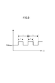
- the block diagram which shows the drive device which concerns on 1st Embodiment, and the linear solenoid valve to which this drive device is connected The circuit diagram which shows this drive device whole. The figure which shows simply the PWM signal used by PWM control.
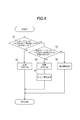
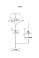
- the flowchart which shows the disconnection determination process which concerns on 1st Embodiment The flowchart which shows the disconnection determination process which concerns on 2nd Embodiment.
- a linear solenoid valve is used as an inductive load that is driven and controlled by the drive device 9 according to the present embodiment.
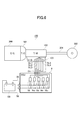
- the automatic transmission 100 includes a torque converter (fluid transmission device) 101 that is drivingly connected to an engine (drive source) 200, and the output rotation of the torque converter 101 is shifted via a propeller shaft 301.
- a torque converter fluid transmission device
- a transmission mechanism 102 that outputs to the wheels 302, a circulating hydraulic pressure of the torque converter 101, an operating hydraulic pressure supplied to a hydraulic servo of a friction engagement element (clutch or brake) (not shown) of the transmission mechanism 102, and a lubricating oil for the transmission mechanism 102
- the hydraulic control device 103 that hydraulically controls a lubricating hydraulic pressure for supplying the oil pressure, and a drive device (ECU) 9 described later in detail are configured.
- ECU drive device
- the driving device 9 is illustrated at a position away from the automatic transmission 100, but actually, the driving device 9 is arranged in a fixed manner adjacent to the side or upper side of the automatic transmission 100, It may be arranged in a form built in the automatic transmission 100. Of course, the drive device 9 may be arranged in a storage box of an electronic device inside a bonnet (not shown).
- FIG. 1 is a configuration diagram showing a part of the drive device and a linear solenoid valve to which the drive device is connected, extracted from the configuration of FIG. 2, and FIG. 2 is a configuration diagram showing the drive device as a whole. It is.
- white control drive units 9a 3 to 9a 5 are omitted except for the control drive unit 9a 1 corresponding to the linear solenoid valve SL1 and the control drive unit 9a 2 corresponding to the linear solenoid valve SL2.
- all of the control drive units 9a 3 to 9a 5 have the same configuration as the control drive units 9a 1 and 9a 2 .
- control drive units 9a 1 to 9a 5 are different in that they are used for linear solenoid valves having different functions, but their configurations are substantially the same. Therefore, in the following, when there is no need to distinguish between them, the overall explanation will be made by omitting the subscripts 1 and 2 given to the reference numerals of the constituent parts provided in the control drive units 9a 1 to 9a 5. There is also. Further, the same components as the control drive units 9a 1 and 9a 2 arranged in the white control drive units 9a 3 to 9a 5 are not shown, but if they are necessary for explanation, they are controlled. It may be described in a form in which subscripts 1 and 2 are added to the end of the reference numerals indicating the same components as those of the drive units 9a 1 and 9a 2 .
- an automatic transmission (not shown) suitable for use in a vehicle is provided with a drive device 9 composed of an ECU (Electronic Control Unit).
- a drive unit (ECU) 9 drives the linear solenoid valves SL1 to SL5 as inductive loads that are driven and controlled in response to drive signals (current signals) being input to the coils 5, respectively. It is connected upstream in the signal supply direction.
- the drive unit 9 includes a control unit 16 having a CPU, a RAM, and a ROM, and control drive units 9a 1 to 9a 5 connected to the control unit 16 and corresponding to the linear solenoid valves (inductive loads) SL1 to SL5, respectively.
- the linear solenoid valves that can be driven by the control drive units 9a 1 to 9a 5 are described as five linear solenoid valves SL1 to SL5.
- the number is not limited to this. There may be 2 to 4 or 6 or more.
- a connector Co which is an example of a connecting portion, is disposed on one side of the board Bo on which a driving device (ECU) 9 is provided.
- the connector Co has connection terminals 65 for connecting the wirings Ha connected to the connectors Co1, Co2, Co3, Co4, and Co5 provided in the linear solenoid valves SL1 to SL5, respectively.
- Connectors Co1 to Co5 attached to the wirings Ha are connected to terminals of terminals (not shown) provided in the solenoid units 1 described later in the linear solenoid valves SL1 to SL5.
- the substrate Bo to drive 9 are provided, are arranged connector 35 battery VB of positive (+) side is connected, the connector 35 connected to the control driver 9a 1, the substrate Bo (See FIG. 6), the positive (+) side of the battery VB is connected to the connection node 28 in each of the control drive units 9a 2 to 9a 5 .
- the substrate Bo, the negative electrode of the battery VB (-) side is disposed a connector 58 to be connected, the control driver 9a 1 ground gt1 via wiring provided on the substrate Bo (refer to FIG. 6 ),
- the negative ( ⁇ ) side of the battery VB is connected to the connection node 29 in each of the control drive units 9a 2 to 9a 5 .
- the linear solenoid valves SL1 to SL5 connected to the connector Co of the drive device 9 are provided in the hydraulic control device 103, and the other end portion 5b of each coil 5 opposite to the one end portion 5a. Are connected to the common terminal 57 via the five wirings 56 and connected to the ground terminal gt of the connector Co of the driving device 9 via the common wiring 57. It is connected to the ground gr1 and the negative electrode ( ⁇ ) of the battery VB.
- the ground portion where the coil 5 is to be frame grounded is connected to the negative electrode side of the battery VB via a valve body (not shown), a vehicle frame (not shown), etc., and therefore has a slight resistance value. Therefore, the potential does not become 0 [V]. For this reason, since the linear solenoid valve has a relatively high ground resistance value even when grounded to the valve body, the operating voltage range may be narrowed.
- the other end portions 5b of the respective coils of the linear solenoid valves SL1 to SL5 are combined into a common wiring 57 via a wiring 56, and the common wiring 57 is connected to the ground terminal gt. ing.
- the ground terminal gt is connected from the connector 58 to the negative electrode ( ⁇ ) of the battery VB via a wiring (not shown) provided on the board Bo.
- the grounds gr1 in the control drive units 9a 1 to 9a 5 are all connected to the negative electrode ( ⁇ ) of the battery VB via a wiring (not shown).
- the other end portion 5b of the coil 5 of each linear solenoid valve is combined into one common wiring 57 and connected to the ground terminal gt in this way, so that a sufficient operating voltage range can be obtained. Can do.
- the ground terminal gt of the drive device 9 is not connected to the negative electrode of the battery VB through only the wiring made of the ground conductor patterned on the board Bo without passing through the valve body or the vehicle frame. This is because the resistance value is extremely low and the potential is close to 0V.
- the disconnection (OPEN) described later in the present embodiment does not mean that the wiring Ha or any of the connectors Co1 to Co5 is disconnected from the connector Co or that the wiring Ha or the wiring 56 itself is disconnected. It is assumed that the common wiring 57 itself that combines 56 into one is cut. In the present embodiment, a description is given of a case where five wirings 56 are combined into one common wiring. However, two or more wirings 56 may be combined into one common wiring, in other words, For example, the two wirings 56 may be combined into a first common wiring, and the remaining three wirings 56 may be combined into a second common wiring.
- the linear solenoid valve SL1 that can be arranged in the hydraulic control device (not shown) has a corresponding control drive unit 9a 1 via the wiring Ha connected to the connector Co1 and the connector Co. It is connected to the.
- the other end 5b of the coil 5 is connected to the low-resistance ground gr1 that is conducted to the ground terminal gt via the wiring 56 and the common wiring 57, and the drive signal is sent to the one end 5a of the coil 5.
- the drive is controlled in response to the input to.
- the linear solenoid valve SL1 is provided in a hydraulic control device, and outputs a supplied hydraulic pressure as a control hydraulic pressure according to an input drive signal.
- Consists of In the solenoid unit 1 a coil 7 is fitted on the outer diameter side of a stator core (not shown), a plunger 6 is arranged opposite to the tip of the stator core, and a shaft 7 fixed integrally with the plunger 6 includes: It is supported by a stator core (not shown). The shaft 7 passes through the center hole of the stator core and abuts against a spool (not shown) of the pressure regulating valve portion.
- the solenoid unit 1 forms a magnetic circuit that passes through the plunger 6 and the stator core based on the current supplied to the coil 5 by being supplied with the drive signal.
- the solenoid unit 1 corresponds to the value of the current that flows through the coil 5 by the attracting part of the plunger 6 and the stator core.
- a magnetic attraction force is generated in the plunger 6, and the movement of the plunger 6 due to the magnetic attraction force is transmitted to the spool via the shaft 7 to operate a pressure regulating valve portion (not shown). Thereby, the output pressure from an output port (not shown) is linearly regulated.
- the mover composed of the shaft 7 and the plunger 6 moves forward and backward in the arrow X direction with respect to the coil 5.
- the drive unit (ECU) 9 is connected to a shift operation lever (not shown) or the like installed in the vicinity of a driver's seat of a vehicle (not shown).
- Control drive units 9a 1 to 9a 5 (see FIG. 2). That is, the drive device 9 has the control drive units 9a 2 to 9a 5 corresponding to the other linear solenoid valves SL2 to SL5 in addition to the control drive unit 9a 1 of FIG. 1 corresponding to the linear solenoid valve SL1. ing.
- the control unit 16 drives and controls the linear solenoid valves SL1 to SL5 via the control driving units 9a 1 to 9a 5 respectively.
- control drive unit 9a 1 corresponding to the linear solenoid valve SL1 is provided in series between the positive electrode (+) side of the battery VB and the ground gr1 conducting to the negative electrode ( ⁇ ) side. and a current path 48 1 and the current path 49 1.
- control drive unit 9a 1 has a current path 50 1 connected to the connection node 27 between the current path 48 1 and the current path 49 1 .
- the current path 50 1, and the connector Co, connection node 27 and one of the terminals 26a and the other terminal 26b each resistor connected between the connector Co (shunt resistor) 25 and is provided .
- Connection node 27 is connected to the current detection circuit 40 1 via the wiring 53 1.
- the first current path is constituted by the current path 48 1 and the current path 50 1
- the second current path is constituted by the current path 49 1 and the current path 50 1, the current path 50 1, the first
- the common current path of the current path and the second current path is configured.
- the current path 48 1, MOSFET as a first switching element connected to the positive electrode side of the battery VB (+) (Metal oxide semiconductor field effect transistor) 17 1 is provided ( hereinafter referred to as the high-side MOSFET17 1).
- the high side MOSFET 17 1 and the low side MOSFET 19 1 are composed of N-channel MOSFETs having the same conductivity type. These MOSFET is composed of a power MOSFET, it is the same MOSFET 18 1 and the current detection MOSFET 20 1 to be described later. Of course, the same applies to the control drive units 9a 2 to 9a 5 .
- the gate G is connected to the PWM drive circuit 31 1 , the drain D that is one end of the current path is connected to the positive (+) side of the battery, and the source S that is the other end of the current path is the connection node (Connecting portion) 27 is connected.
- the gate G is connected to the PWM drive circuit 32 1 , the source S that is one end of the current path is connected to the ground gr 1, and the drain D that is the other end of the current path is connected to the connection node 27. ing.
- PWM drive circuit 31 1, 32 1 of the signal generation control unit supplies the respective PWM signal (control signal) to the high side MOSFET 17 1 and the low MOSFET 19 1, a positive electrode of the battery VB (+) side and the one end of the coil 5 a current path 48 1, 50 1 between the 5a, a drive signal current paths 49 1, 50 1 and, by switching to the cutoff state to the conductive state between the end portion 5a of the ground gr1 side and the coil 5 PWM control is performed to generate.
- the control drive units 9a 2 to 9a 5 the same applies to the control drive units 9a 2 to 9a 5 .
- the high-side MOSFET 17 1 functions to control the current to supply a drive signal to the linear solenoid valve SL1
- the low-side MOSFET 19 1 is used when the high-side MOSFET 17 1 is off. It functions to release the energy stored in the linear solenoid valve SL1. That is, in the driving device 9, adopts a synchronous rectifying system, the high side MOSFET 17 1 controls the amount of energy supplied input ON, and OFF the linear solenoid valve SL1, the low-side MOSFET 19 1 is linear solenoid A rectifying operation for supplying the energy of the valve SL1 to an output voltage different from the input is performed.
- control driver 9a 1 of the driving device 9 includes a MOSFET 18 1 and the current detection MOSFET 20 1 of N-channel type of the same conductivity type as the high-side MOSFET 17 1 and the low side MOSFET 19 1.
- MOSFET 18 1 the gate G is connected to the PWM drive circuit 31 1
- the drain D is one end of a current path is connected between the high side MOSFET 17 1 and the battery of the positive electrode in the current path 48 1 (+) .
- Source S which is the other end of the current path in the MOSFET 18 1 is connected to the current detection circuit 40 1 to be described later.
- Reference numeral 51 in FIG. 1 shows a connection node connecting the respective gates G of the MOSFET 18 1 and the high side MOSFET 17 1 to the output of the PWM drive circuit 31 1.
- Current detecting MOSFET 20 1 a gate G is connected to the PWM drive circuit 32 1, a source S is one end of the current path, the source S and the ground gr1 is one end of a current path of the low-side MOSFET 19 1 in the current path 49 1 Are connected to a connection node (connection unit) 29 between the two. Drain D, which is the other end of the current path in the current detecting MOSFET 20 1 is connected to the current detection circuit 40 1.
- Reference numeral 30 denotes a connection node for connecting the gates G of the current detection MOSFET 20 1 and the low-side MOSFET 19 1 to the output of the PWM drive circuit 32 1 .
- Control driver 9a high side MOSFET 17 1 provided on one low-side MOSFET 19 1, MOSFET 18 1 and the current detection MOSFET 20 1 are both constructed from enhancement type N-channel MOSFET.
- the control drive unit 9a 1 includes the PWM drive circuits 31 1 and 32 1 , the current detection circuit 40 1, and the current detection circuit 34 1 that are connected to the control unit 16.
- the PWM drive circuit 31 1 supplies a PWM signal (see FIG. 3) as a control signal to the gate G of the high-side MOSFET 17 1 based on a command from the control unit 16, and the PWM drive circuit 32 1 receives a command from the control unit 16.
- supplying a PWM signal is a control signal to the gate G of the low-side MOSFET 19 1 based on.
- the PWM drive circuits 31 1 , 32 1 serving as the signal generation control unit connect the current path 48 1, the current path 50 1 , the current path 49 1, and the current path 50 1 with a conduction state and a cutoff state.
- the PWM control is performed so as to generate a drive signal to the linear solenoid valve SL1.
- PWM drive circuit 31 1 the high-order side MOSFET 17 MOSFET 18 1 of the gate G with first gate G is connected
- PWM drive circuit 31 1 is PWM signal, for example, High in the high side MOSFET 17 first gate G ( +) Low after the application of the (-) when applying the, Low after the PWM signal high (+) is applied to MOSFET 18 1 of the gate G (-) is applied
- MOSFET 18 1 is a high-side MOSFET 17 1 It operates at the same timing (same phase) as.
- the PWM drive circuit 32 1, the gate G of the current detection MOSFET 20 1 is connected with the low-side MOSFET 19 1 of the gate G, the PWM drive circuit 32 1 is the low-side MOSFET 19 1 of the gate G to the PWM signal, for example, High (+) Low after the application of the (-) when applying the, Low after the PWM signal High (+) is applied to the gate G of the low-side MOSFET 19 1 (-) is applied to the current detecting MOSFET 20 1 There operates at the same timing (same phase) and low-side MOSFET 19 1. Of course, the same applies to the control drive units 9a 2 to 9a 5 .
- Current detecting circuit 34 the high-side MOSFET 17 1 and the low-side MOSFET 19 1 from the voltage PWM signal to the coil 5 is generated across the resistor 25 when supplied (voltage drop) to detect the current value with the differential amplifier , and it outputs a signal differential amplifier to notch filter (NF) 47 1 controller 16 via a.
- the connected resistor 25 between a connection node 27 and the connector Co in the current path 50 has one terminal 26a is composed of an operational amplifier current detecting circuit 34 1 of the inverting input terminal (-) to 34a is connected, the other terminal 26b is connected to the non-inverting input terminal (+) 34b of the current detection circuit 34 1.
- Current detecting circuit 40 constantly monitoring the current which is fed back at the time of supply of the drive signal to the linear solenoid valve SL1 via the current detection MOSFET 20 1.
- Current detecting circuit 34 1 is composed of an operational amplifier (Operational Amplifier), it is possible to detect the current flowing through the coil 5 via the current path 50 1 of the common current path.
- the current detection circuit 34 1 can also constitute a current monitoring unit that monitors the current flowing through the current paths 49 1 and 50 1 during PWM control by the PWM drive circuits 31 1 and 32 1 .
- the current path 50 1 is a common current path of said first and second current paths, the resistor 25 are connected in series. Of course, the same applies to the control drive units 9a 2 to 9a 5 .
- the control unit 16 outputs the drive signals from the PWM drive circuits 31 1 and 32 1 , flows to the current paths (common current paths) 50 1 and 50 2, and is monitored by the current detection circuits (current monitor units) 40 1 and 40 2.
- the feedback current is controlled so that an appropriate PWM signal is output from the PWM drive circuits 31 1 and 32 1 using the current to be fed as the feedback current.
- the control unit 16 also includes command values of drive signals output from the PWM drive circuits 31 1 and 32 1 corresponding to two of the linear solenoid valves SL1 to SL5 (for example, SL1 and SL2), and the drive signals.
- the current detection circuits 34 1 and 34 2 can also be used as the current monitor unit.
- two of the linear solenoid valves SL1 to SL5 mean linear solenoid valves that are operated by PWM control so as to simultaneously engage engaging elements (not shown) such as clutches and brakes by their respective operations. .
- the linear solenoid valves SL1 to SL5 are provided, and the gears are always shifted by simultaneously engaging a plurality of (for example, two or more) linear solenoid valves, so that one common wiring 57 is disconnected.
- an abnormality for example, the drive current that flows through the corresponding coil 5 by the ON operation of the high-side MOSFET 17 1 of the control drive unit 9a 1 corresponding to the linear solenoid valve SL1 flows into the ground gr1 via the common wiring 57.
- the low MOSFET 19 2 side of the corresponding control driver 9a 2 in operation for example, a linear solenoid valve SL2 to the simultaneous engagement of clutches and brakes (Fig. 2), wire 56 and a coil 5 and its corresponding It is thought that it flows in via.
- the command value of the PWM signal by the PWM drive circuit 31 1 corresponding to the linear solenoid valve SL1 for example at 1 [A] 0 command value is, for example, PWM signal by the PWM drive circuit 32 2 corresponding to the linear solenoid valve SL2 If it is .1 [a], with respect to the command value 1 [a] in one of the linear solenoid valves SL1 side, since the current to be monitored by the current detecting circuit 40 1 is reduced, the control unit 16, the state The current (feedback current) on the other linear solenoid valve SL2 side is determined. During this determination, in the linear solenoid valve SL2 side, when the current being monitored by the current detection circuit 40 2 is command value 0.1 [A] is smaller than, the control unit 16 determines this state as disconnection abnormality occurs .
- This phenomenon is determined not only in the case of the linear solenoid valves SL1 and SL2, but also in other combinations in which the linear solenoid valves SL1 to SL5 operate so as to simultaneously engage the clutch and the brake.
- the control unit 16 determines that a disconnection abnormality has occurred. However, in this case, even if a current smaller than the command value is detected on one of the linear solenoid valves that are operated so as to be simultaneously engaged, if the current smaller than the command value is not detected on the other side, the control unit 16 will be described later. As described above, it is determined that another abnormality other than the disconnection of the common wiring 57 has occurred.
- FIG. 4 is a flowchart showing disconnection determination processing according to the present embodiment.
- the operation is performed as follows when the common wiring 57 is not disconnected abnormally.
- a shift operation lever (not shown) is operated and switched to, for example, the D range (drive range)
- the high side is driven by the PWM drive circuits 31 and 32 in each control drive unit 9a based on a command from the control unit 16.
- the MOSFET 17 and the low-side MOSFET 19 are turned on alternately.
- each solenoid part 1 of the linear solenoid valves SL1 and SL2 is driven linearly by changing the duty ratio (ratio of on-time) and performing feedback control while variably controlling the average output of the passing time.
- the PWM drive circuits 31 and 32 send a PWM signal having a PWM pulse width T (that is, a high pulse width) at a constant cycle t via the connection nodes 51 and 30 as shown in FIG. This is applied to each gate G of the MOSFET 17 and the low-side MOSFET 19. Then, the PWM signals are respectively applied to the gates G so that the high-side MOSFET 17 is turned on when the pulse of the PWM signal is High (+) and turned off when the pulse of the PWM signal is Low ( ⁇ ).
- the low-side MOSFET 19 operates so as to be turned on when the pulse is High (+) and turned off when the pulse is Low ( ⁇ ) by a PWM signal out of phase with the PWM signal on the high-side MOSFET 17 side.
- the drive signal (current signal) corresponding to the PWM signal passes through the current path between the drain and source of the high-side MOSFET 17 and also passes through the current path between the source and drain of the low-side MOSFET 19 to pass through the current path 50 and the wiring Ha.
- Is supplied to one end portion 5a of the coil 5 of the solenoid unit 1 and, for example, the linear solenoid valves SL1 and SL2 are operated so as to simultaneously engage the clutch and the brake. For this reason, when disconnection abnormality or the like does not occur, the spools of the linear solenoid valves SL1 and SL2 are linearly driven.
- control unit 16 While operating as described above, the control unit 16 constantly monitors the disconnection abnormality of one common wiring 57 via the current detection circuits 40 1 and 40 2 .
- the control unit 16 determines that the disconnection abnormality of the common wiring 57 has occurred based on the current change of the feedback current monitored by the current detection circuits 40 1 and 40 2 of the control drive units 9a 1 and 9a 2 .
- a disconnection determination process is performed. First, among the control driver 9a 1 ⁇ 9a 5, the linear solenoid valves SL1, SL2 example be driven so as to simultaneously engage the clutches and brakes, for outputting the respective current by the PWM drive circuit 31 2, 32 2 And the current (feedback current) that flows through the current paths 50 1 and 50 2 and is monitored by the current detection circuits 40 1 and 40 2 are compared. Then, the control unit 16, in step S1, the current path 50 1 of one of the linear solenoid valve SL1 side, it is determined whether a small electric current flows than the command value.
- the drive signal high side MOSFET 17 1 in the control drive unit 9a 1 is turned from a current path 50 1 is input to the coil 5 of the linear solenoid valve SL1
- the wiring 56 is input from the connection portion 60 through the coil 5 of the linear solenoid valve SL2
- the current path (common current path) of the control drive unit 9a 2 flows to 50 2, as compared with the case where the common line 57 is not broken at least the resistance value of the coil portion of the linear solenoid valve SL2 is increased, for example so that the smaller the feedback current than the command value of the PWM drive circuit 31 1 is detected by the current detecting circuit 40 1.
- This phenomenon also when outputting the drive signal from the high-side MOSFET 17 2 in the control driver 9a 2 side, the smaller the feedback current than the command value of the PWM drive circuit 31 2 is detected by the current detecting circuit 40 2 become.
- control unit 16 in step S1 for example, PWM drive circuit 31 is smaller than the command value of the PWM control command to the first current (feedback current) is equal to or flows in a current path 50 1.
- the control unit 16 turns on the normal flag in step S ⁇ b> 2, and continues the shift process assuming that the disconnection abnormality of the common wiring 57 has not occurred.
- step S1 when a current smaller than the command value is judged to flow through the current path 50 1, in step S3, the current path 50 2 of the other of the linear solenoid valve SL2 side, the command It is determined whether or not a current smaller than the value flows.
- step S4 the control unit 16 turns on the disconnection flag, determines that a disconnection abnormality has occurred, proceeds to step S5, and outputs an error signal.
- the control unit 16 When the error signal is output, the control unit 16 immediately stops the PWM control by the PWM drive circuits 31 1 , 32 1 , and the clutch and the linear solenoid valves SL 1 to SL 5 including the linear solenoid valves SL 1 and SL 2 All the brake engagement operations are cut off, and a display with a lamp or the like is displayed on a display panel arranged in a driver's seat (not shown), for example, to alert the driver.
- the control unit 16 in step S3, the current path 50 2 of the other linear solenoid valve SL2 side, when a current smaller than the command value is determined not to flow, at step S6, the other abnormalities Judge that there is. That is, the control unit 16 may detect a feedback current smaller than the command value on one side of the linear solenoid valve that operates to simultaneously engage the clutch and the brake, but does not detect a feedback current smaller than the command value on the other side. The control unit 16 determines that another abnormality (abnormality due to another cause) other than the disconnection of the common wiring 57 has occurred.
- the control unit 16 when a disconnection abnormality occurs in one common wiring 57 in which all of the linear solenoid valves SL1 to SL5 are collectively grounded to the ground gr1, the control unit 16 causes the PWM drive circuit 31 to operate. , 32, a current smaller than the command value of the PWM control commanded to the current path (common current path) 50 can be determined, so that the occurrence of disconnection abnormality can be quickly determined.
- the control drive units 9a 1 to 9a 5 are controlled by the control unit 16 so as not to output PWM signals from any of the PWM drive circuits 31 1 to 31 5 and 32 1 to 32 5 .
- FIG. 5 is a flowchart showing disconnection determination processing according to the present embodiment.
- the configurations shown in FIGS. 1 and 2 are all the same, but in the first embodiment, a current monitoring unit for the current flowing in the current paths (common current paths) 50 1 to 50 5
- the current detection circuits 34 1 to 34 5 that have been used only as a current direction are also used as a current direction detection unit that detects the direction of the current flowing between both terminals of the resistors 25 of the current paths 50 1 to 50 5 .
- the current detection as a current direction detection unit for detecting the direction of the current flowing through each of the current paths (common current paths) 50 1 to 50 5 by the control drive units 9a 1 to 9a 5 in FIG. Circuits 34 1 to 34 5 are provided. Then, the control unit 16, the command of the drive signal when the reverse current is detected by the current detecting circuits 34 1 34 5 determines that the disconnection abnormality occurrence.
- the control driver 9a 2 corresponding to the linear solenoid valve SL2 When abnormal disconnection occurs in the common line 57, for example, the high side MOSFET 17 1 of the control drive unit 9a 1 corresponding to the linear solenoid valve SL1 is at a timing operation ON, the control driver 9a 2 corresponding to the linear solenoid valve SL2
- the drive current flowing through the coil 5 to its corresponding with oN operation of the high side MOSFET 17 1 is that it can not flow into the ground gr1 through the common wiring 57, simultaneously engaging the clutch or the like the low MOSFET 19 2 side of the control driver 9a 2 which operates as is conceivable that flows through the wiring 56 and the coil 5 its corresponding.
- 0 command value is, for example, PWM signal by the PWM drive circuit 31 2 corresponding to the linear solenoid valve SL2 .1 [A]
- the current monitored by the current detection circuit 40 1 (or the current detection circuit 34 1 ) is smaller than the command value 1 [A] on the linear solenoid valve SL1 side
- reverse current is detected by the current detection circuit 40 2 and the drive command signals It will be.
- the control part 16 determines with this state having generate
- step S11 the control unit 16, for example by low MOSFET 19 2 of ON in one of the two PWM driving circuit for driving to the simultaneous engagement of the clutch or the like (31 2), the current path (common current path) 50 2 determines whether a reverse current flows. As a result, if it is determined that no reverse current is flowing, the control unit 16 turns on the normal flag in step S12, and continues the shift process assuming that the disconnection abnormality of the common wiring 57 has not occurred.
- step S11 determines that a reverse current has flowed
- the control unit 16 turns on the disconnection flag in step S13, determines that a disconnection abnormality has occurred, proceeds to step S14, and outputs an error signal.
- the control unit 16 immediately stops the PWM control by the PWM drive circuits 31 1 , 32 1 , and the clutch and the linear solenoid valves SL 1 to SL 5 including the linear solenoid valves SL 1 and SL 2 All brake engagement operations are cut off, and a display with a lamp or the like is displayed on a display panel (not shown) to alert the driver.
- the control unit 16 generates a current in the direction opposite to the command of the drive signal based on the command timing of the PWM signal to the low-side MOSFET 19 of each of the plurality of control drive units 9a 1 to 9a 5.
- the detection circuit 34 it can be determined that the disconnection abnormality of the common wiring 57 has occurred. Also according to this embodiment, it is possible to obtain the same effect as that of the first embodiment.
- the current detection circuit 34 according to the second embodiment is used for disconnection determination (see FIG. 4) based on the magnitude of the feedback current by the current detection circuits 40 1 to 40 5 according to the first embodiment described above.
- 1-34 5 disconnection determination based on detection of the reverse current due to (see FIG. 5), a disconnection abnormality of the common wiring 57, it is possible to more accurately detect.
- the current detection circuits 34 1 to 34 5 are configured to detect the reverse current flowing in the current paths (common current paths) 50 1 to 50 5.
- the control drive units 9 a 1 to 9 a 9a 5 The current detection circuits 40 1 to 40 5 detect that currents that should not flow at the current operation timing flow through the low-side MOSFETs 19 1 to 19 5 via the current detection MOSFETs 20 1 to 20 5 , respectively. In this case, it is possible to make an abnormality determination as occurrence of reverse current.
- control drive units 9a 1 to 9a 5 are respectively connected to the other end portions 5b of the linear solenoid valves SL1 to SL5 at the downstream side of the drive signal supply direction of the battery VB.
- the negative electrode (ground terminal gt) side it is not limited to this configuration.
- each of the other end portions 5b of the linear solenoid valves SL1 to SL5 can be configured to be connected to the positive electrode (+) side of the battery VB on the downstream side in the drive signal supply direction.
- the drive device (9) has one end (5a) and the other end (5b), and drive control is performed in response to input of drive signals.
- the driving device (9) for controlling a plurality of inductive loads (SL1 to SL5) in which the other end (5b) is connected to one of the positive electrode and the negative electrode of the battery (VB), A plurality of wirings (Ha) connected to one end (5a) of each of the plurality of inductive loads (SL1 to SL5), and a second end (5b) of the plurality of inductive loads (SL1 to SL5).
- a connecting portion (Co) is provided for connecting a common wiring (57) in which two or more of the plurality of wirings (56) connected to each other are collectively used.
- the common wiring 57 in which two or more of the plurality of wirings 56 connected to each of the other end portions 5b of the plurality of linear solenoid valves SL1 to SL5 are collectively connected to the connector Co that is the connection portion. Since the configuration is adopted, the number of ground terminals gt of the connector Co can be reduced, and the connector Co can be downsized. Further, the wiring 56 can be simplified as compared with the case where the plurality of wirings 56 are directly connected to the driving device 9, and for example, the wiring of the oil pan (not shown) that houses the hydraulic control device 103 is also good. It is also possible to simplify the wiring connection work when manufacturing the automatic transmission 100.
- the drive device (9) includes a control unit (16), A plurality of control drive units (9a 1 to 9a 5 ) connected to the control unit (16) and respectively connected to the one end portions of the plurality of inductive loads;
- the plurality of control drive units (9a 1 to 9a 5 ) are respectively A first switching element (17 1 to 17 5 ) connected to be electrically connected to the positive electrode side of the battery;
- a second switching element (19 1 to 19 5 ) connected to the negative electrode side of the battery;
- a control signal is supplied to each of the first switching element and the second switching element, and a first current path (48 1 ) between the one end (5a) of the inductive load and the positive electrode side of the battery.
- the one pole is a negative electrode (gr1, gt).
- the control unit (16) corresponds to at least two of the plurality of inductive loads (SL1 to SL5) (for example, SL1 and SL2).
- the command value of the drive signal output from the signal generation control unit (for example, 31 1 , 32 1 ) and the current monitor after flowing through the common current path (50 1 , 50 2 ) after the output of the drive signal The current monitored by the units (40 1 , 40 2 ) is compared, and when the current in the common current path is smaller than the command value, it is determined that the disconnection abnormality has occurred.
- the plurality of control drive units (9a 1 to 9a 5 ) detect the directions of currents flowing through the common current paths (50 1 to 50 5 ), respectively.
- the control unit (16) When the current in the direction opposite to the command of the drive signal is detected by the current direction detector (34 1 to 34 5 ), it is determined that the disconnection abnormality has occurred.
- the first switching element and the second switching element are the same conductivity type high side MOSFET (17 1 to 17 5 ) and low side MOSFET (19).
- the high-side MOSFET (17 1 ⁇ 17 5) is connected to the gate (G) is the signal generation control unit (31 1 to 31 5 of the corresponding one), and a current path one end (D) of the battery Connected to the positive side
- the low-side MOSFET (19 1 ⁇ 19 5) is connected to the gate (G) is the signal generation control unit (32 1 to 32 5 of the corresponding one), and one end of the current path (S) is a negative electrode of the battery Connected to the (gr1) side,
- the gate (G) is connected to
- the linear solenoid valve SL1 can be appropriately driven and controlled via the high-side MOSFET 17 and the low-side MOSFET 19, and the control unit 16 can control the current detection circuit via the current-detecting MOSFET 20 connected to the low-side MOSFET 19.
- the control unit 16 can control the current detection circuit via the current-detecting MOSFET 20 connected to the low-side MOSFET 19.
- the drive device 9 is described as an example using an N-channel MOSFET as a switching element.
- the present invention is not limited to this, and for example, a drive using a P-channel MOSFET is used. There may be.
- the switching element a bipolar transistor can be used instead of the MOSFET, and further, another switching element that performs a mechanical switching operation can be used.
- the drive device 9 that uses a linear solenoid valve and can be used as a transmission for a vehicle has been described.
- a motor / generator is mounted instead of a torque converter.
- It may be a drive device as a transmission device for a hybrid vehicle using a linear solenoid valve, or may be a drive device as a transmission device for an electric vehicle (Electric Vehicle) that drives the vehicle with an electric motor. Good.
- Electric Vehicle Electric Vehicle
- This drive device can be used for a device that electrically controls a solenoid valve that controls hydraulic pressure, and is particularly suitable for a device that requires a reduction in the size of a connecting portion of the drive device.
Landscapes
- Engineering & Computer Science (AREA)
- Power Engineering (AREA)
- Mechanical Engineering (AREA)
- Magnetically Actuated Valves (AREA)
- Emergency Protection Circuit Devices (AREA)
- Electronic Switches (AREA)
- Control Of Transmission Device (AREA)
Abstract
Description
前記複数の誘導性負荷の一端部のそれぞれに接続される複数の配線と、前記複数の誘導性負荷の他端部のそれぞれに接続される複数の配線の2本以上をまとめて共通化した共通配線と、を接続する接続部を備える。
以下、本第1の実施の形態について、図1乃至図4、及び図6に沿って説明する。なお、本実施の形態に係る駆動装置9が駆動制御する誘導性負荷として、リニアソレノイドバルブを用いている。
まず、本実施の形態に係る駆動装置9及び自動変速機100の概略構成について説明する。図6に示すように、自動変速機100は、エンジン(駆動源)200に駆動連結されるトルクコンバータ(流体伝動装置)101と、トルクコンバータ101の出力回転を変速してプロペラシャフト301を介して車輪302に出力する変速機構102と、それらトルクコンバータ101の循環油圧、変速機構102の不図示の摩擦係合要素(クラッチやブレーキ)の油圧サーボに供給する作動油圧、並びに変速機構102に潤滑油を供給するための潤滑油圧などを油圧制御する油圧制御装置103と、詳しくは後述する駆動装置(ECU)9と、を備えて構成されている。油圧制御装置103には、摩擦係合要素の油圧サーボの係合圧などを油圧制御する例えば5本のリニアソレノイドバルブSL1~SL5が内蔵される形で配置されている。なお、図6において駆動装置9は、自動変速機100から離れた位置に記載しているが、実際には自動変速機100の側方或いは上方に隣接して固定される形で配置されたり、自動変速機100の内部に内蔵される形で配置されたりする。勿論であるが、駆動装置9は、不図示のボンネットの内部における電子機器の収納ボックス内などに配置されていてもよい。
続いて、本実施の形態に係る駆動装置9及びその関連する構成部分について、図1及び図2に沿って説明する。図1は、本駆動装置及び該駆動装置が接続されるリニアソレノイドバルブを、図2の構成から一部抜粋して示す構成図であり、図2は、本駆動装置を全体的に示す構成図である。図2では、リニアソレノイドバルブSL1に対応する制御駆動部9a1、及びリニアソレノイドバルブSL2に対応する制御駆動部9a2以外は、便宜上、図示を省略した白抜きの制御駆動部9a3~9a5として記載しているが、制御駆動部9a3~9a5はいずれも上記制御駆動部9a1、9a2と同様の構成を備えている。
次に、第2の実施の形態について図2及び図5を参照して説明する。図5は、本実施の形態に係る断線判定処理を示すフローチャートである。なお、本実施の形態では、図1及び図2に示した構成は全て同様であるが、第1の実施の形態では電流路(共通電流路)501~505に流れる電流の電流モニタ部としてのみ使用していた電流検出回路341~345を、電流路501~505の抵抗器25の両端子間を流れる電流の方向を検出する電流方向検出部としても用いている。
以上説明したように、本実施の形態に係る駆動装置(9)は、一端部(5a)と他端部(5b)とを夫々有し、駆動信号が夫々入力されることに応じて駆動制御され、前記他端部(5b)がバッテリ(VB)の正極と負極との一方の極に接続される複数の誘導性負荷(SL1~SL5)を制御する駆動装置(9)において、
前記複数の誘導性負荷(SL1~SL5)の一端部(5a)のそれぞれに接続される複数の配線(Ha)と、前記複数の誘導性負荷(SL1~SL5)の他端部(5b)のそれぞれに接続される複数の配線(56)の2本以上をまとめて共通化した共通配線(57)と、を接続する接続部(Co)を備える。
前記制御部(16)に接続され、前記複数の誘導性負荷の前記一端部に夫々接続された複数の制御駆動部(9a1~9a5)と、を備え、
前記複数の制御駆動部(9a1~9a5)は夫々、
前記バッテリの正極側に導通するように接続された第1のスイッチング素子(171~175)と、
前記バッテリの負極側に接続された第2のスイッチング素子(191~195)と、
前記第1のスイッチング素子及び前記第2のスイッチング素子に夫々制御信号を供給し、前記誘導性負荷の前記一端部(5a)と前記バッテリの正極側との間の第1の電流路(481~485,501~505)と、前記誘導性負荷の前記一端部(5a)と前記バッテリの負極側との間の第2の電流路(491~495,501~505)とを、導通状態と遮断状態とに切換えて前記駆動信号を生成するように制御する信号生成制御部(311~315,321~325)と、
前記信号生成制御部(311~315,321~325)による前記制御時に、前記第1の電流路(481~485,501~505)及び前記第2の電流路(491~495,501~505)に共通する共通電流路(501~505)に流れる電流をモニタリングする電流モニタ部(341~345,401~405)と、を有し、
前記制御部(16)は、
各前記制御駆動部(9a1~9a5)の前記電流モニタ部(341~345,401~405)によりモニタリングしている前記共通電流路(501~505)の電流変化に基づき、前記共通配線(57)の断線異常が発生していると判定する断線判定処理(S4,S13)を実行する。
前記制御部(16)が、
前記駆動信号の指令とは逆方向の電流が前記電流方向検出部(341~345)により検出された場合に、前記断線異常の発生と判定する。
前記ハイサイドMOSFET(171~175)及び前記ローサイドMOSFET(191~195)と同じ導電型の電流検出用MOSFET(201~205)を備え、
前記ハイサイドMOSFET(171~175)は、ゲート(G)が前記信号生成制御部(311~315の対応するもの)に接続され、且つ電流路の一端(D)が前記バッテリの正極側に接続され、
前記ローサイドMOSFET(191~195)は、ゲート(G)が前記信号生成制御部(321~325の対応するもの)に接続され、且つ電流路の一端(S)が前記バッテリの負極(gr1)側に接続され、
前記電流検出用MOSFET(201~205)は、ゲート(G)が前記信号生成制御部(321~325の対応するもの)に接続され、電流路の一端(S)が前記第2のスイッチング素子(191~195の対応するもの)の前記電流路の一端(S)と前記負極(gr1)側との間に接続され、且つ電流路の他端(D)が前記電流モニタ部(401~405の対応するもの)に接続されている。
なお、以上説明した実施の形態においては、駆動装置9を、スイッチング素子としてNチャネル型のMOSFETを用いるものを一例として説明したが、これに限らず、例えばPチャネル型のMOSFETを用いたものであってもよい。また、スイッチング素子としては、MOSFETに代えてバイポーラトランジスタを用いることも可能であり、更には、機械的にスイッチング動作する他のスイッチング素子を用いることも可能である。
5b…誘導性負荷の他端部(リニアソレノイドバルブの他端部)
9…駆動装置
9a1~9a5…制御駆動部
16…制御部
171~175…第1のスイッチング素子(ハイサイドMOSFET)
191~195…第2のスイッチング素子(ローサイドMOSFET)
201~205…電流検出用MOSFET
311~315,321~325…信号生成制御部(PWM駆動回路)
341~345…電流モニタ部,電流方向検出部(電流検出回路)
401~405…電流モニタ部(電流検出回路)
481~485,491~495,501~505…第1の電流路,第2の電流路,共通電流路(電流路)
57…共通配線
Co…接続部(コネクタ)
D…電流路の一端
G…ゲート
gr1,gt…他方の極,負極(グランド,グランド端子)
S…電流路の一端
S4,13…断線判定処理
SL1~SL5…誘導性負荷(リニアソレノイドバルブ)
VB…バッテリ
Claims (6)
- 一端部と他端部とを夫々有し、駆動信号が夫々入力されることに応じて駆動制御され、前記他端部がバッテリの正極と負極との一方の極に接続される複数の誘導性負荷を制御する駆動装置において、
前記複数の誘導性負荷の一端部のそれぞれに接続される複数の配線と、前記複数の誘導性負荷の他端部のそれぞれに接続される複数の配線の2本以上をまとめて共通化した共通配線と、を接続する接続部を備える、
駆動装置。 - 制御部と、
前記制御部に接続され、前記複数の誘導性負荷の前記一端部に夫々接続された複数の制御駆動部と、を備え、
前記複数の制御駆動部は夫々、
前記バッテリの正極側に導通するように接続された第1のスイッチング素子と、
前記バッテリの負極側に接続された第2のスイッチング素子と、
前記第1のスイッチング素子及び前記第2のスイッチング素子に夫々制御信号を供給し、前記誘導性負荷の前記一端部と前記バッテリの正極側との間の第1の電流路と、前記誘導性負荷の前記一端部と前記バッテリの負極側との間の第2の電流路とを、導通状態と遮断状態とに切換えて前記駆動信号を生成するように制御する信号生成制御部と、
前記信号生成制御部による前記制御時に、前記第1の電流路及び前記第2の電流路に共通する共通電流路に流れる電流をモニタリングする電流モニタ部と、を有し、
前記制御部は、
各前記制御駆動部の前記電流モニタ部によりモニタリングしている前記共通電流路の電流変化に基づき、前記共通配線の断線異常が発生していると判定する断線判定処理を実行する、
請求項1に記載の駆動装置。 - 前記一方の極は負極である、
請求項2に記載の駆動装置。 - 前記制御部は、
前記複数の誘導性負荷のうちの少なくとも2つにおいて夫々対応する前記信号生成制御部から出力される前記駆動信号の指令値と、該駆動信号の出力後に夫々の前記共通電流路に流れて前記電流モニタ部でモニタリングされる電流とを比較し、該共通電流路の電流が前記指令値よりも小さい場合に、前記断線異常の発生と判定する、
請求項2または3に記載の駆動装置。 - 前記複数の制御駆動部は夫々、前記共通電流路を流れる電流の方向を検出する電流方向検出部を有し、
前記制御部は、
前記駆動信号の指令とは逆方向の電流が前記電流方向検出部により検出された場合に、前記断線異常の発生と判定する、
請求項2ないし4のいずれか1項に記載の駆動装置。 - 前記第1のスイッチング素子及び前記第2のスイッチング素子は、互いに同じ導電型のハイサイドMOSFET及びローサイドMOSFETから構成され、
前記ハイサイドMOSFET及び前記ローサイドMOSFETと同じ導電型の電流検出用MOSFETを備え、
前記ハイサイドMOSFETは、ゲートが前記信号生成制御部に接続され、且つ電流路の一端が前記バッテリの正極側に接続され、
前記ローサイドMOSFETは、ゲートが前記信号生成制御部に接続され、且つ電流路の一端が前記バッテリの負極側に接続され、
前記電流検出用MOSFETは、ゲートが前記信号生成制御部に接続され、電流路の一端が前記第2のスイッチング素子の前記電流路の一端と前記負極側との間に接続され、且つ電流路の他端が前記電流モニタ部に接続されている、
請求項2ないし5のいずれか1項に記載の駆動装置。
Priority Applications (4)
| Application Number | Priority Date | Filing Date | Title |
|---|---|---|---|
| JP2017543617A JP6702333B2 (ja) | 2015-09-30 | 2016-09-30 | 駆動装置 |
| US15/745,893 US11152782B2 (en) | 2015-09-30 | 2016-09-30 | Drive device |
| CN201680056955.6A CN108141208B (zh) | 2015-09-30 | 2016-09-30 | 驱动装置 |
| DE112016003306.0T DE112016003306T5 (de) | 2015-09-30 | 2016-09-30 | Antriebsvorrichtung |
Applications Claiming Priority (2)
| Application Number | Priority Date | Filing Date | Title |
|---|---|---|---|
| JP2015-194353 | 2015-09-30 | ||
| JP2015194353 | 2015-09-30 |
Publications (1)
| Publication Number | Publication Date |
|---|---|
| WO2017057682A1 true WO2017057682A1 (ja) | 2017-04-06 |
Family
ID=58427581
Family Applications (1)
| Application Number | Title | Priority Date | Filing Date |
|---|---|---|---|
| PCT/JP2016/079030 Ceased WO2017057682A1 (ja) | 2015-09-30 | 2016-09-30 | 駆動装置 |
Country Status (5)
| Country | Link |
|---|---|
| US (1) | US11152782B2 (ja) |
| JP (1) | JP6702333B2 (ja) |
| CN (1) | CN108141208B (ja) |
| DE (1) | DE112016003306T5 (ja) |
| WO (1) | WO2017057682A1 (ja) |
Cited By (5)
| Publication number | Priority date | Publication date | Assignee | Title |
|---|---|---|---|---|
| WO2018110134A1 (ja) * | 2016-12-16 | 2018-06-21 | 日立オートモティブシステムズ株式会社 | 車載制御装置 |
| JPWO2020213318A1 (ja) * | 2019-04-19 | 2020-10-22 | ||
| WO2022270020A1 (ja) * | 2021-06-23 | 2022-12-29 | 日立Astemo株式会社 | 電子制御装置、電子制御装置の制御方法 |
| US11990897B2 (en) | 2019-05-28 | 2024-05-21 | Hitachi Astemo, Ltd. | Current control device for control of supply current with low-side and high-side switch elements and duration measurement |
| WO2025027763A1 (ja) * | 2023-07-31 | 2025-02-06 | 日立Astemo株式会社 | 負荷駆動装置 |
Families Citing this family (1)
| Publication number | Priority date | Publication date | Assignee | Title |
|---|---|---|---|---|
| US11332157B2 (en) * | 2018-07-03 | 2022-05-17 | Mitsubishi Electric Corporation | Vehicle control apparatus |
Citations (4)
| Publication number | Priority date | Publication date | Assignee | Title |
|---|---|---|---|---|
| JP2006203415A (ja) * | 2005-01-19 | 2006-08-03 | Toyota Motor Corp | リニアソレノイド駆動回路 |
| JP2006303992A (ja) * | 2005-04-21 | 2006-11-02 | Calsonic Kansei Corp | 誘導性負荷駆動装置 |
| JP2008253122A (ja) * | 2007-03-07 | 2008-10-16 | Denso Corp | 負荷駆動装置及び負荷駆動方法 |
| JP2012085038A (ja) * | 2010-10-08 | 2012-04-26 | Denso Corp | 負荷制御装置 |
Family Cites Families (14)
| Publication number | Priority date | Publication date | Assignee | Title |
|---|---|---|---|---|
| JP3008924B2 (ja) * | 1998-04-10 | 2000-02-14 | 富士電機株式会社 | パワー素子のドライブ回路 |
| EP1177609B1 (de) * | 2000-03-01 | 2012-06-13 | Robert Bosch Gmbh | Fail-safe für bürstenlose gleichstromantriebe |
| JP2002084175A (ja) | 2000-06-29 | 2002-03-22 | Denso Corp | 電子制御装置及びソレノイド駆動装置 |
| JP2003075476A (ja) * | 2001-09-07 | 2003-03-12 | Denso Corp | 誘導性負荷の電流検出装置 |
| JP4113436B2 (ja) * | 2003-01-24 | 2008-07-09 | 三菱電機株式会社 | ゲートドライブ装置 |
| GB0308674D0 (en) * | 2003-04-15 | 2003-05-21 | Koninkl Philips Electronics Nv | Driver for inductive load |
| JP4075955B1 (ja) | 2006-11-24 | 2008-04-16 | いすゞ自動車株式会社 | 診断装置 |
| DE102007055837B4 (de) | 2007-03-07 | 2011-04-28 | Denso Corporation, Kariya-City | Last-Ansteuerverfahren |
| DE102008014677A1 (de) | 2008-03-18 | 2009-09-24 | Continental Automotive Gmbh | Verfahren und Vorrichtung zum Betreiben einer Schaltungsanordnung |
| JP5083235B2 (ja) * | 2009-01-30 | 2012-11-28 | アイシン・エィ・ダブリュ株式会社 | 動力伝達装置およびこれを搭載する車両 |
| JP2011023802A (ja) | 2009-07-13 | 2011-02-03 | Denso Corp | 誘導性負荷制御装置 |
| JP5411630B2 (ja) * | 2009-09-03 | 2014-02-12 | ローム株式会社 | 負荷駆動装置 |
| CN202634816U (zh) * | 2012-05-25 | 2012-12-26 | 无锡实益达电子有限公司 | 小型化低电磁干扰的led驱动电源 |
| RU2572378C2 (ru) * | 2013-03-04 | 2016-01-10 | Федеральное государственное образовательное бюджетное учреждение высшего профессионального образования "Сибирский государственный университет телекоммуникаций и информатики" (ФГОБУ ВПО "СибГУТИ" | Устройство защиты светодиодов от перегрузок |
-
2016
- 2016-09-30 JP JP2017543617A patent/JP6702333B2/ja active Active
- 2016-09-30 CN CN201680056955.6A patent/CN108141208B/zh active Active
- 2016-09-30 WO PCT/JP2016/079030 patent/WO2017057682A1/ja not_active Ceased
- 2016-09-30 US US15/745,893 patent/US11152782B2/en active Active
- 2016-09-30 DE DE112016003306.0T patent/DE112016003306T5/de not_active Withdrawn
Patent Citations (4)
| Publication number | Priority date | Publication date | Assignee | Title |
|---|---|---|---|---|
| JP2006203415A (ja) * | 2005-01-19 | 2006-08-03 | Toyota Motor Corp | リニアソレノイド駆動回路 |
| JP2006303992A (ja) * | 2005-04-21 | 2006-11-02 | Calsonic Kansei Corp | 誘導性負荷駆動装置 |
| JP2008253122A (ja) * | 2007-03-07 | 2008-10-16 | Denso Corp | 負荷駆動装置及び負荷駆動方法 |
| JP2012085038A (ja) * | 2010-10-08 | 2012-04-26 | Denso Corp | 負荷制御装置 |
Cited By (11)
| Publication number | Priority date | Publication date | Assignee | Title |
|---|---|---|---|---|
| WO2018110134A1 (ja) * | 2016-12-16 | 2018-06-21 | 日立オートモティブシステムズ株式会社 | 車載制御装置 |
| US10976375B2 (en) | 2016-12-16 | 2021-04-13 | Hitachi Automotive Systems, Ltd. | On-board controller |
| JPWO2020213318A1 (ja) * | 2019-04-19 | 2020-10-22 | ||
| JP7284810B2 (ja) | 2019-04-19 | 2023-05-31 | 日立Astemo株式会社 | 負荷駆動装置および負荷駆動装置の制御方法 |
| US11824528B2 (en) | 2019-04-19 | 2023-11-21 | Hitachi Astemo, Ltd. | Load drive device and control method of load drive device |
| US11990897B2 (en) | 2019-05-28 | 2024-05-21 | Hitachi Astemo, Ltd. | Current control device for control of supply current with low-side and high-side switch elements and duration measurement |
| WO2022270020A1 (ja) * | 2021-06-23 | 2022-12-29 | 日立Astemo株式会社 | 電子制御装置、電子制御装置の制御方法 |
| JPWO2022270020A1 (ja) * | 2021-06-23 | 2022-12-29 | ||
| JP7675361B2 (ja) | 2021-06-23 | 2025-05-14 | Astemo株式会社 | 電子制御装置、電子制御装置の制御方法 |
| US12319211B2 (en) | 2021-06-23 | 2025-06-03 | Hitachi Astemo, Ltd. | Electronic control device and method for controlling electronic control device |
| WO2025027763A1 (ja) * | 2023-07-31 | 2025-02-06 | 日立Astemo株式会社 | 負荷駆動装置 |
Also Published As
| Publication number | Publication date |
|---|---|
| JPWO2017057682A1 (ja) | 2018-04-19 |
| JP6702333B2 (ja) | 2020-06-03 |
| CN108141208B (zh) | 2021-05-28 |
| US20180212419A1 (en) | 2018-07-26 |
| DE112016003306T5 (de) | 2018-04-19 |
| CN108141208A (zh) | 2018-06-08 |
| US11152782B2 (en) | 2021-10-19 |
Similar Documents
| Publication | Publication Date | Title |
|---|---|---|
| JP6455597B2 (ja) | 駆動装置 | |
| JP6702333B2 (ja) | 駆動装置 | |
| JP5776607B2 (ja) | 誘導性負荷駆動装置 | |
| US9435461B2 (en) | Controller of electromagnetic valve driving circuit and abnormality diagnosing method for electromagnetic valve driving circuit | |
| TW201945876A (zh) | 電磁閥系統 | |
| KR20200071175A (ko) | 진단 장치 및 방법 | |
| JP6015586B2 (ja) | Pwm制御装置およびそのpwm制御方法 | |
| JP2014073036A (ja) | 電源装置および電源装置の異常判定方法 | |
| JP4672054B2 (ja) | モータ制御装置 | |
| JP2013044668A (ja) | 負荷駆動装置 | |
| US12447914B2 (en) | Vehicle-mounted control device | |
| US11824528B2 (en) | Load drive device and control method of load drive device | |
| JP7675361B2 (ja) | 電子制御装置、電子制御装置の制御方法 | |
| JP7313183B2 (ja) | 電子制御装置及び異常検出方法 | |
| JP7073189B2 (ja) | 電子制御装置 | |
| KR101870827B1 (ko) | 가변력 솔레노이드 단락진단 장치 및 방법 | |
| JP2011202530A (ja) | 燃料ポンプ制御装置 | |
| JP2016081969A (ja) | 電子制御装置 | |
| JP6668474B2 (ja) | 電子制御装置 | |
| JP2022006515A (ja) | 車載制御装置 | |
| JP4303716B2 (ja) | 負荷駆動回路およびその異常検出方法 | |
| JP2009231409A (ja) | リニアソレノイド駆動装置 | |
| KR102759418B1 (ko) | 차량의 변속을 위한 스위치 모니터링 장치 | |
| JP4983274B2 (ja) | 車両の電力供給装置 | |
| JP2010208579A (ja) | 電子制御ユニット |
Legal Events
| Date | Code | Title | Description |
|---|---|---|---|
| 121 | Ep: the epo has been informed by wipo that ep was designated in this application |
Ref document number: 16851851 Country of ref document: EP Kind code of ref document: A1 |
|
| ENP | Entry into the national phase |
Ref document number: 2017543617 Country of ref document: JP Kind code of ref document: A |
|
| WWE | Wipo information: entry into national phase |
Ref document number: 15745893 Country of ref document: US |
|
| WWE | Wipo information: entry into national phase |
Ref document number: 112016003306 Country of ref document: DE |
|
| 122 | Ep: pct application non-entry in european phase |
Ref document number: 16851851 Country of ref document: EP Kind code of ref document: A1 |