WO2017057065A1 - 循環排煙システム - Google Patents
循環排煙システム Download PDFInfo
- Publication number
- WO2017057065A1 WO2017057065A1 PCT/JP2016/077466 JP2016077466W WO2017057065A1 WO 2017057065 A1 WO2017057065 A1 WO 2017057065A1 JP 2016077466 W JP2016077466 W JP 2016077466W WO 2017057065 A1 WO2017057065 A1 WO 2017057065A1
- Authority
- WO
- WIPO (PCT)
- Prior art keywords
- circulation
- flow rate
- circulating
- smoke
- input voltage
- Prior art date
- Legal status (The legal status is an assumption and is not a legal conclusion. Google has not performed a legal analysis and makes no representation as to the accuracy of the status listed.)
- Ceased
Links
Images



Classifications
-
- A—HUMAN NECESSITIES
- A61—MEDICAL OR VETERINARY SCIENCE; HYGIENE
- A61B—DIAGNOSIS; SURGERY; IDENTIFICATION
- A61B18/00—Surgical instruments, devices or methods for transferring non-mechanical forms of energy to or from the body
- A61B18/04—Surgical instruments, devices or methods for transferring non-mechanical forms of energy to or from the body by heating
- A61B18/12—Surgical instruments, devices or methods for transferring non-mechanical forms of energy to or from the body by heating by passing a current through the tissue to be heated, e.g. high-frequency current
- A61B18/14—Probes or electrodes therefor
- A61B18/1402—Probes for open surgery
-
- A—HUMAN NECESSITIES
- A61—MEDICAL OR VETERINARY SCIENCE; HYGIENE
- A61B—DIAGNOSIS; SURGERY; IDENTIFICATION
- A61B1/00—Instruments for performing medical examinations of the interior of cavities or tubes of the body by visual or photographical inspection, e.g. endoscopes; Illuminating arrangements therefor
- A61B1/00002—Operational features of endoscopes
- A61B1/00004—Operational features of endoscopes characterised by electronic signal processing
- A61B1/00006—Operational features of endoscopes characterised by electronic signal processing of control signals
-
- A—HUMAN NECESSITIES
- A61—MEDICAL OR VETERINARY SCIENCE; HYGIENE
- A61B—DIAGNOSIS; SURGERY; IDENTIFICATION
- A61B1/00—Instruments for performing medical examinations of the interior of cavities or tubes of the body by visual or photographical inspection, e.g. endoscopes; Illuminating arrangements therefor
- A61B1/012—Instruments for performing medical examinations of the interior of cavities or tubes of the body by visual or photographical inspection, e.g. endoscopes; Illuminating arrangements therefor characterised by internal passages or accessories therefor
- A61B1/015—Control of fluid supply or evacuation
-
- A—HUMAN NECESSITIES
- A61—MEDICAL OR VETERINARY SCIENCE; HYGIENE
- A61B—DIAGNOSIS; SURGERY; IDENTIFICATION
- A61B17/00—Surgical instruments, devices or methods
-
- A—HUMAN NECESSITIES
- A61—MEDICAL OR VETERINARY SCIENCE; HYGIENE
- A61B—DIAGNOSIS; SURGERY; IDENTIFICATION
- A61B5/00—Measuring for diagnostic purposes; Identification of persons
- A61B5/03—Measuring fluid pressure within the body other than blood pressure, e.g. cerebral pressure ; Measuring pressure in body tissues or organs
- A61B5/036—Measuring fluid pressure within the body other than blood pressure, e.g. cerebral pressure ; Measuring pressure in body tissues or organs by means introduced into body tracts
-
- A—HUMAN NECESSITIES
- A61—MEDICAL OR VETERINARY SCIENCE; HYGIENE
- A61B—DIAGNOSIS; SURGERY; IDENTIFICATION
- A61B18/00—Surgical instruments, devices or methods for transferring non-mechanical forms of energy to or from the body
- A61B2018/00571—Surgical instruments, devices or methods for transferring non-mechanical forms of energy to or from the body for achieving a particular surgical effect
- A61B2018/00607—Coagulation and cutting with the same instrument
-
- A—HUMAN NECESSITIES
- A61—MEDICAL OR VETERINARY SCIENCE; HYGIENE
- A61B—DIAGNOSIS; SURGERY; IDENTIFICATION
- A61B18/00—Surgical instruments, devices or methods for transferring non-mechanical forms of energy to or from the body
- A61B2018/00636—Sensing and controlling the application of energy
- A61B2018/00696—Controlled or regulated parameters
- A61B2018/00744—Fluid flow
-
- A—HUMAN NECESSITIES
- A61—MEDICAL OR VETERINARY SCIENCE; HYGIENE
- A61B—DIAGNOSIS; SURGERY; IDENTIFICATION
- A61B18/00—Surgical instruments, devices or methods for transferring non-mechanical forms of energy to or from the body
- A61B2018/00636—Sensing and controlling the application of energy
- A61B2018/00773—Sensed parameters
- A61B2018/00779—Power or energy
-
- A—HUMAN NECESSITIES
- A61—MEDICAL OR VETERINARY SCIENCE; HYGIENE
- A61B—DIAGNOSIS; SURGERY; IDENTIFICATION
- A61B18/00—Surgical instruments, devices or methods for transferring non-mechanical forms of energy to or from the body
- A61B2018/00636—Sensing and controlling the application of energy
- A61B2018/00773—Sensed parameters
- A61B2018/00892—Voltage
-
- A—HUMAN NECESSITIES
- A61—MEDICAL OR VETERINARY SCIENCE; HYGIENE
- A61B—DIAGNOSIS; SURGERY; IDENTIFICATION
- A61B18/00—Surgical instruments, devices or methods for transferring non-mechanical forms of energy to or from the body
- A61B2018/0091—Handpieces of the surgical instrument or device
- A61B2018/00916—Handpieces of the surgical instrument or device with means for switching or controlling the main function of the instrument or device
- A61B2018/00928—Handpieces of the surgical instrument or device with means for switching or controlling the main function of the instrument or device by sending a signal to an external energy source
-
- A—HUMAN NECESSITIES
- A61—MEDICAL OR VETERINARY SCIENCE; HYGIENE
- A61B—DIAGNOSIS; SURGERY; IDENTIFICATION
- A61B18/00—Surgical instruments, devices or methods for transferring non-mechanical forms of energy to or from the body
- A61B18/04—Surgical instruments, devices or methods for transferring non-mechanical forms of energy to or from the body by heating
- A61B18/12—Surgical instruments, devices or methods for transferring non-mechanical forms of energy to or from the body by heating by passing a current through the tissue to be heated, e.g. high-frequency current
- A61B18/14—Probes or electrodes therefor
- A61B2018/1405—Electrodes having a specific shape
- A61B2018/1412—Blade
-
- A—HUMAN NECESSITIES
- A61—MEDICAL OR VETERINARY SCIENCE; HYGIENE
- A61B—DIAGNOSIS; SURGERY; IDENTIFICATION
- A61B2218/00—Details of surgical instruments, devices or methods for transferring non-mechanical forms of energy to or from the body
- A61B2218/001—Details of surgical instruments, devices or methods for transferring non-mechanical forms of energy to or from the body having means for irrigation and/or aspiration of substances to and/or from the surgical site
- A61B2218/007—Aspiration
- A61B2218/008—Aspiration for smoke evacuation
-
- A—HUMAN NECESSITIES
- A61—MEDICAL OR VETERINARY SCIENCE; HYGIENE
- A61M—DEVICES FOR INTRODUCING MEDIA INTO, OR ONTO, THE BODY; DEVICES FOR TRANSDUCING BODY MEDIA OR FOR TAKING MEDIA FROM THE BODY; DEVICES FOR PRODUCING OR ENDING SLEEP OR STUPOR
- A61M2202/00—Special media to be introduced, removed or treated
- A61M2202/02—Gases
- A61M2202/0225—Carbon oxides, e.g. Carbon dioxide
Definitions
- the present invention relates to a circulation smoke exhaust system.
- the conventional smoke evacuation device controls air supply and smoke emission, respectively, resulting in a deviation in the timing of air supply and smoke emission, changing the pressure in the abdominal cavity, expanding or reducing the abdominal cavity,
- the endoscopic image which is a captured image of the affected area, may be moved to hinder the treatment.
- an object of the present invention is to provide a circulation smoke exhaust system that can perform circulation smoke exhaust as necessary when necessary.
- a circulation smoke exhaust system receives setting output information of a treatment instrument device including a treatment instrument, sends a predetermined gas, and sucks smoke generated in the body together with the gas in the body. And determining the pump input voltage corresponding to the circulation flow rate of the circulation smoke according to the set output information of the treatment instrument device.
- An input voltage determination unit, and a circulation flow rate control unit that controls the circulation flow rate by outputting the pump input voltage to the pump.
- FIG. 1 is a block diagram showing a configuration of a circulation smoke exhaust system 1 according to an embodiment of the present invention.
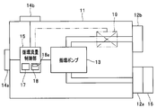
- FIG. 2 is a block diagram showing a configuration of the circulation smoke exhaust device 11 of the circulation smoke exhaust system 1 according to the embodiment of the present invention.
- the circulation smoke exhaust system 1 of the embodiment is used for an operation in which the inside of a body cavity of a patient K is expanded by feeding a gas such as carbon dioxide gas under an endoscopic observation, and a treatment tool such as an electric knife 22 is used. .
- the circulation smoke exhaust system 1 includes a circulation smoke exhaust apparatus 11, a treatment instrument apparatus 21, an insufflation apparatus 31, and an endoscope apparatus 41.
- a suction trocar T1, a treatment instrument trocar T2, and an insufflation trocar T3 are inserted into the body cavity of the patient K.
- the circulation smoke exhaust device 11 includes a suction port 12 a, an air supply port 12 b, a circulation pump 13, connection portions 14 a and 14 b, and a circulation flow rate control unit 15. .
- the circulation smoke exhaust device 11 receives setting output information of the treatment instrument device provided with the treatment instrument, sends a predetermined gas, and sucks the smoke generated in the body together with the gas in the body to perform the circulation smoke. Configured to be able to. Circulating flue gas is generated during the treatment with the electric knife 22 by the filter 16 (to be described later) by circulating the gas (here, carbon dioxide) fed into the body cavity by the insufflation device 31 through the circulation pump 13. This is done by filtering the smoke or mist (both represented by “smoke”).
- the suction port 12a is connected to the suction trocar T1 via the circulation suction tube B1.
- the filter 16 is attached to the suction port 12a.
- the filter 16 is made of, for example, a non-woven fabric or the like, and is configured to filter the sucked smoke.
- the air supply port 12b is connected to the air supply trocar T3 via the circulation air supply tube B2.
- the circulation pump 13 is connected to the circulation flow rate control unit 15 and is driven based on the control signal of the circulation flow rate control unit 15, and sucks air through the circulation suction tube B1 connected to the suction port 12a and enters the air supply port 12b. Air is supplied through the connected circulating air supply tube B2. That is, the circulation pump 13 is a pump for circulating smoke in the circulating smoke exhaust device 11.
- connection units 14a and 14b are configured by connectors to which communication cables can be connected.
- the connecting portion 14a is connected to the treatment instrument device 21 via the communication cable C1.
- the connection part 14b is connected to the pneumoperitoneum apparatus 31 via the communication cable C2.
- the circulation flow rate control unit 15 is connected to the connection units 14 a and 14 b and the circulation pump 13.
- the circulation flow rate control unit 15 includes a central processing unit (hereinafter referred to as “CPU”) 17 and a memory 18 including a ROM and a RAM.
- CPU central processing unit
- the function of the circulation flow rate control unit 15 is realized by the CPU 17 executing various programs stored in the memory 18.
- the circulating flow rate control unit 15 is configured to control a circulating flow rate by outputting a pump input voltage described later to the circulating pump 13. More specifically, the circulation flow rate control unit 15 acquires setting output information from the treatment instrument device 21 via the communication cable C1 connected to the connection unit 14a, and the input voltage determination unit 18a responds to the setting output information. A circulation pump input voltage is determined, a voltage supplied from an external power source (not shown) is converted into a circulation pump input voltage, and the circulation pump input voltage is output to the circulation pump 13 to control the circulation flow rate.
- Circulation flow control unit 15 can start or stop circulation smoke by a control signal input from insufflation apparatus 31 via communication cable C2 connected to connection unit 14b.
- the memory 18 stores various programs including the input voltage determination unit 18a.
- the input voltage determination unit 18a is a processing unit that determines, as the pump input voltage, a voltage corresponding to the circulation flow rate according to the setting output information of the treatment instrument device 21 based on the setting output information of the treatment instrument device 21.
- the input voltage determination unit 18a determines a pump input voltage corresponding to a predetermined circulation flow rate Z when the electric knife is in an OFF state.
- the input voltage determination unit 18a determines a pump input voltage corresponding to the circulation flow rate according to the output level of the electric knife 22.
- the input voltage determination unit 18a determines the pump input voltage so that the circulation flow rate becomes the first circulation flow rate when the treatment instrument setting mode is the incision mode as the first mode, and the input voltage determination unit 18a determines the pump input voltage so that the circulation flow rate becomes the second circulation flow rate smaller than the first circulation flow rate when the setting mode of the treatment instrument is the coagulation mode as the second mode.
- the treatment instrument device 21 includes an electric knife device body 23, an electric knife 22 as a treatment tool, and a foot switch 24.
- the treatment instrument device 21 can output setting output information of the electric knife 22 to the circulation smoke exhaust device 11.
- the electric knife device main body 23 can output a high-frequency current to the electric knife 22.
- the electric scalpel device body 23 can switch the setting mode by an operator's instruction input to an operation unit 22a or a foot switch 24 described later, and outputs a high-frequency current corresponding to the setting mode to the electric scalpel 22.
- the setting mode includes an incision mode and a coagulation mode.
- the electric scalpel device main body 23 can adjust the output level by, for example, “large”, “medium”, “small”, etc., by an operator's instruction input to an operation unit (not shown).
- the electric knife device main body 23 outputs the set output information of the high-frequency current output to the electric knife 22 to the circulation flow rate control unit 15 of the circulation smoke exhaust device 11 via the communication cable C1.
- the setting output information includes setting mode information of the electric knife 22 and output level information of the electric knife 22.
- the incision mode is a mode in which a high-frequency current is output to the affected tissue and the affected tissue is transpired by Joule heat to incise.
- the coagulation mode is a mode in which a high-frequency current is intermittently output to the affected tissue and the affected tissue is thermally coagulated by Joule heat.
- the electric knife 22 is connected to the electric knife device main body 23 and is inserted into the body cavity from the treatment instrument trocar T2.
- the electric knife 22 outputs a high-frequency current supplied from the electric knife device main body 23 to a diseased part from a chip (not shown) provided at the tip of the electric knife 22.
- the electric knife 22 is configured to include an operation unit 22a, and an operator can input a mode switching instruction by operating the operation unit 22a with fingers.
- the electric knife 22 may be any type of electric knife 22 such as a monopolar type, a bipolar type, a ball tip type, or a tweezers type.
- the tip of the electric knife 22 may have any shape such as a blade shape, a needle shape, a ball shape, or a loop shape.
- the insufflation apparatus 31 is connected to the connection part 14b of the circulation smoke exhaust apparatus 11.
- the insufflation apparatus 31 is connected to an insufflation trocar T3 through an insufflation tube B3.
- the insufflation apparatus 31 is connected to a cylinder 32 filled with gas (here, carbon dioxide gas).
- the insufflation apparatus 31 includes an insufflation valve 33, a pressure sensor 34, a relief valve 35, and an insufflation control unit 36.
- the pneumoperitoneum 31 supplies air into the body cavity of the patient K until the body cavity pressure reaches the set pressure so that an appropriate endoscopic image can be obtained by the endoscope apparatus 41. So that the volume in the body cavity of the patient K is expanded.
- the set pressure is set to any pressure in the range of 5 mmHG to 20 mmHG, for example, in accordance with the surgical procedure.
- the air supply valve 33 is provided in an insufflation duct 37 connected to the insufflation tube B3.
- the air supply valve 33 is connected to the insufflation control unit 36 and is configured to be opened and closed by a control signal from the insufflation control unit 36.
- the insufflation control unit 36 opens the insufflation valve 33 to supply air from the cylinder 32 into the body cavity of the patient K via the insufflation tube B3 connected to the insufflation trocar T3.
- the pressure sensor 34 is provided in the insufflation duct 37.
- the pressure sensor 34 is connected to the insufflation control unit 36.
- the pressure sensor 34 measures the pressure in the body cavity by measuring the pressure in the pneumoperitoneal duct 37, and outputs the measured body cavity pressure information to the pneumoperitoneum control unit 36.
- the relief valve 35 is provided in the insufflation duct 37.
- the relief valve 35 is connected to the insufflation control unit 36.
- the relief valve 35 is opened to lower the body cavity pressure.
- the insufflation control unit 36 includes a CPU 38 and a memory 39 including a ROM and a RAM.
- the function of the insufflation control unit 36 is realized by the CPU 38 executing various programs stored in the memory 39.
- the memory 39 stores various programs including an insufflation process program 39a.
- the insufflation process program 39a is a processing unit that performs an insufflation process.
- the pneumoperitoneum processing program 39a transmits a control signal for starting the circulation smoke to the circulation smoke exhausting device 11, and the body cavity pressure exceeds the set value. Then, a control signal for opening the relief valve 35 is transmitted to the relief valve 35.
- the set pressure is set in advance to a pressure suitable for surgery performed by expanding the body cavity.
- the endoscope apparatus 41 includes an endoscope 42, a light source device 43, a processor 44, and a monitor 45.
- the endoscope 42 is connected to the processor 44 and the light source device 43, and is inserted into the body cavity from the air supply trocar T3.
- the endoscope 42 is configured to have an observation window (not shown) at the distal end, and can image the inside of the body cavity.
- the light source device 43 guides the light emitted from the semiconductor light source by the light guide member, adjusts the color, light intensity distribution, and the like by the light conversion member provided at the tip of the light guide member, and illuminates the endoscope 42 with illumination light. Can be supplied.
- the processor 44 can supply power to the endoscope 42, process an image captured by the endoscope 42, generate image information, and output the image information to a connected monitor 45.
- the monitor 45 can display image information input from the processor 44.
- FIG. 3 is a flowchart showing the flow of the insufflation process of the circulation smoke exhaust system 1 according to the embodiment of the present invention.
- the CPU 38 When the surgeon inputs an instruction to start processing to the pneumoperitoneum 31 using an operation unit (not shown), the CPU 38 reads the pneumoperitoneum processing program 39a from the memory 39 and starts the pneumoperitoneum process.
- a process start instruction input to the pneumoperitoneum 31 is also input to the circulation smoke exhaust device 11 via the communication cable C2, and the CPU 17 reads various programs relating to the circulation smoke exhaustion processing including the input voltage determination unit 18a. Prepare for the start of circulating smoke treatment.
- the pneumoperitoneum control unit 36 detects the body cavity pressure (step “hereinafter abbreviated as S” 1). In S ⁇ b> 1, the pneumoperitone control unit 36 detects the body cavity pressure measured by the pressure sensor 34.
- the pneumoperitoneum control unit 36 determines whether or not the body cavity pressure is the same as the set pressure (S2). In S2, the pneumoperitoneum control unit 36 determines whether the body cavity pressure acquired by the pressure sensor 34 is the same as the preset pressure, and the body cavity pressure and the preset pressure are the same. When it is determined (S2: Yes), the process proceeds to S2Y. On the other hand, when it is determined that the body cavity pressure is different from the set pressure (S2: No), the process proceeds to S3. The body cavity pressure and the set pressure may be determined to be the same as long as the difference between them is within a predetermined range.
- a control signal for instructing the circulation smoke exhaust device 11 to start circulation smoke emission is transmitted.
- the circulation smoke exhaust device 11 starts a circulation smoke exhaustion process (S21 to S24) described later.
- the insufflation control unit 36 ends the insufflation process.
- the pneumoperitone control unit 36 turns off the circulation pump 13 (S3).
- the pneumoperitone control unit 36 transmits a control signal for stopping the operation of the circulation pump 13 to the circulation flow rate control unit 15.
- the circulation flow rate control unit 15 turns off the circulation pump 13 and stops the operation.
- the pneumoperitoneum control unit 36 determines whether or not the body cavity pressure exceeds the set pressure (S4).
- the pneumoperitoneum control unit 36 compares the body cavity pressure acquired by the pressure sensor 34 with the set pressure, and determines that the body cavity pressure does not exceed the set pressure (S4: No), the process proceeds to S5. move on.
- the pneumoperitoneum control unit 36 proceeds to S31 in order to perform the relief process of S4Y.
- the insufflation control unit 36 starts air supply.
- the insufflation control unit 36 opens the insufflation valve 33 and supplies the gas into the body cavity of the patient K for a predetermined time P through the insufflation tube B3.
- the predetermined time P is, for example, 1 second.
- the pneumoperitone control unit 36 stops the air supply (S6).
- the insufflation control unit 36 stops air supply and returns the process to S1.
- the processing from S1 to S6 constitutes a pneumoperitoneum process.
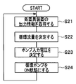
- FIG. 4 is a flowchart showing a flow of the circulation smoke treatment in the circulation smoke removal device 11 of the circulation smoke removal system 1 according to the embodiment of the present invention.
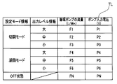
- FIG. 5 is an explanatory diagram illustrating an example of the flow rate voltage table TL of the circulation smoke exhaust system 1 according to the embodiment of the present invention.
- the circulation flow rate control unit 15 acquires setting output information of the treatment instrument device 21 (S21).
- the circulation flow rate control unit 15 acquires setting output information of the treatment instrument device 21 via the connection unit 14a.
- Circulation flow rate control unit 15 determines the circulation flow rate (S22). In S22, the circulation flow rate control unit 15 starts processing of the input voltage determination unit 18a, refers to the flow rate voltage table TL by the processing of the input voltage determination unit 18a, and sets the setting output information acquired from the treatment instrument device 21. Determine the circulation flow rate accordingly.
- FIG. 5 is an example of the flow rate voltage table TL.
- the flow rate of the circulation pump 13 is determined by setting mode information and output level information included in the setting output information. For example, when the electric knife 22 is in the incision mode and the output level information is “large”, the flow rate of the circulation pump 13 is determined to be F1 L / Min (F1 liters per minute), and the output level information is “medium”. At some point, it is determined to be F2L / Min, and when the output level information is “small”, it is determined to be F3L / Min.
- the flow rate of the circulation pump 13 is determined as F4L / Min, and when the output level information is “medium”, F5L / Min. When the output level information is “small”, it is determined as F6L / Min. When the electric knife 22 is in the OFF state, the flow rate of the circulation pump 13 is determined to be FNL / Min.
- Circulation flow control unit 15 determines the pump input voltage (S23). In S23, the circulation flow rate control unit 15 determines the pump input voltage from the flow rate of the circulation pump 13 determined in S22 by referring to the flow rate voltage table TL by the processing of the input voltage determination unit 18a.
- the pump input voltage is determined to be P1V (volt).
- the pump input voltages are P2V and P3V. , P4V, P5V, P6V, and PNV.
- 5 is an example of the flow voltage table TL, and is not limited to the table shown in FIG.
- the circulation flow rate control unit 15 turns on the circulation pump 13 (S24).
- S24 the circulation flow rate control unit 15 turns on the circulation pump 13, and circulates and smokes based on the pump input voltage determined in S23.
- the process returns to S21. Thereby, for example, when the electric knife 22 is switched from the incision mode to the coagulation mode, when the output level information of the electric knife 22 is changed, or when the electric knife 22 is switched from the ON state to the OFF state. Circulation smoke is exhausted by the circulation flow rate according to the set output information of the treatment instrument device 21.
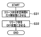
- FIG. 6 is a flowchart showing the flow of the relief process of the circulating smoke exhaust system 1 according to the embodiment of the present invention.
- the insufflation controller 36 opens the relief valve 35 for a predetermined time R (S31).
- the pneumoperitone control unit 36 transmits a control signal for opening the relief valve 35 for a predetermined time R to the relief valve 35.
- the relief valve 35 that has received the control signal from the insufflation control unit 36 opens for a predetermined time R and discharges the gas in the body cavity to the outside.
- the pneumoperitone control unit 36 closes the relief valve 35 (S32). After performing the process of S32, the pneumoperitoneum control unit 36 ends the pneumoperitoneum process and the relief process.
- circulation smoke is exhausted according to the setting mode and output level of the treatment instrument device 21, and circulation smoke can be exhausted as necessary when necessary.
- the flow rate adjustment valve 19 is connected to the circulation flow rate control unit 15 and is configured to be able to open and close the valve by a control signal of the circulation flow rate control unit 15.
- the circulation flow rate is immediately changed.
- the circulation flow amount is changed to a predetermined time D.
- the predetermined time D is, for example, any time from 1 second to 10 seconds.
- a plurality of predetermined times D may be set according to the setting mode and output level of the electric knife 22. According to this configuration, since the smoke exhaustion continues for a predetermined time D even after the electric knife 22 is turned off, it is possible to suck and remove the smoke more reliably.
- circulation smoke exhaustion is started when the body cavity pressure reaches the set pressure.
- an instruction input to turn on the electric knife 22 is performed by an operation unit (not shown), and the circulation smoke exhaust apparatus 11 circulates. After the start of smoke emission, the electric knife 22 may be turned on. More specifically, after an instruction is input by the operation unit, the treatment instrument device 21 transmits a control signal to the circulation smoke exhaust device 11 to start circulation smoke exhaustion (broken line arrow C1a in FIG. 1), and the circulation exhaust After the smoke device 11 starts circulating smoke exhaustion, a control signal is transmitted to the treatment instrument device 21 (broken line arrow C1b in FIG.
- the electric knife 22 may be turned on. According to this configuration, when the electric scalpel 22 is turned on, circulating smoke has already started, and the smoke generated at the moment when the electric scalpel 22 is turned on is also sucked and removed.
- the setting mode of the electric knife 22 is configured by an incision mode and a coagulation mode, but is not limited thereto.
- the setting mode of the electric knife 22 may include other modes such as a spray coagulation mode in which a wide range of tissue is hemostatically caused by arc discharge.
- the input voltage determination unit 18a determines the circulation pump input voltage based on the flow rate voltage table.
- the flow rate voltage table is not necessarily required, and the circulation pump input voltage is determined based on a predetermined calculation formula. It doesn't matter.
- the input voltage determination part 18a is arrange
- the setting output information of the treatment instrument device 21 may be output to the pneumoperitoneum device 31 via the circulation smoke exhaust device 11, or the treatment instrument device 21 and the pneumoperitoneum device 31 are connected by a communication cable (not shown).
- the setting output information may be directly output from the treatment instrument device 21 to the pneumoperitoneum device 31.
- the circulation smoke exhaust system 1 of embodiment removes the smoke which generate
- FIG. 7 is an explanatory cross-sectional view illustrating the configuration of the distal end 111 of the endoscope insertion portion of the endoscope 101.
- the endoscope insertion portion distal end 111 includes an objective lens 131 and an air supply conduit 121.
- the objective lens 131 is provided on the distal end surface 112 of the endoscope insertion portion, and is configured to be able to capture the reflected light of the treatment site J.
- An imaging element (not shown) is provided behind the objective lens 131 and converts reflected light from the treatment site J into image information.
- the air supply duct 121 is provided inside the endoscope insertion portion distal end 111, is connected to an endoscope main body (not shown), and is configured to supply air from the endoscope main body toward the endoscope insertion portion distal end surface 112. Is done.
- the air supply duct 121 may be built in the endoscope insertion portion distal end 111 or may be externally attached along the outer periphery of the endoscope insertion portion distal end 111.
- the central axis X1 of the air supply pipe 121 is configured to be inclined so as to face the optical axis X2 direction of the objective lens 131 so that the gas sent out from the air supply pipe 121 blows against the smoke generated from the treatment site J.
- the FIG. 7 shows, for example, a position where the optical axis X2 of the objective lens 131 and the central axis X1 of the air supply pipe 121 intersect, and a predetermined distance L from the objective lens 131 (for example, this distance L is the focal point of the objective lens 131).
- the predetermined distance L is, for example, 100 mm.
- air can be supplied to the treatment site J, and the suspended matter in the observation visual field of the endoscope 101 can be efficiently blown off to obtain a good field of view.
Landscapes
- Health & Medical Sciences (AREA)
- Life Sciences & Earth Sciences (AREA)
- Surgery (AREA)
- Engineering & Computer Science (AREA)
- Veterinary Medicine (AREA)
- Public Health (AREA)
- Heart & Thoracic Surgery (AREA)
- Medical Informatics (AREA)
- Molecular Biology (AREA)
- Animal Behavior & Ethology (AREA)
- General Health & Medical Sciences (AREA)
- Biomedical Technology (AREA)
- Physics & Mathematics (AREA)
- Nuclear Medicine, Radiotherapy & Molecular Imaging (AREA)
- Biophysics (AREA)
- Pathology (AREA)
- Optics & Photonics (AREA)
- Radiology & Medical Imaging (AREA)
- Plasma & Fusion (AREA)
- Otolaryngology (AREA)
- Hematology (AREA)
- Signal Processing (AREA)
- Surgical Instruments (AREA)
- Endoscopes (AREA)
Abstract
循環排煙システムは、処置具22を備えた処置具装置21の設定出力情報を受信し、所定の気体を送気するとともに、体内で発生した煙を体内の気体と共に吸引して循環排煙を行う循環排煙装置11と、循環排煙のためのポンプと、処置具装置21の設定出力情報に応じた循環排煙の循環流量に相当するポンプ入力電圧を決定する入力電圧決定部18aと、ポンプ入力電圧をポンプに出力して循環流量を制御する循環流量制御部15と、を有して構成される。
Description
本発明は、循環排煙システムに関する。
従来、例えば、日本国特開2006-288553号公報に示すように、炭酸ガスを腹腔内に送気し、電気メスによる処置の際に発生する煙を電気メスの出力値に応じて外部に排煙する電気手術装置の排煙装置が提案されている。
しかしながら、従来の排煙装置は、送気と排煙をそれぞれ制御する結果、送気と排煙のタイミングにずれが生じ、腹腔内の圧力を変化させ、腹腔内を拡張又は縮小させ、患部や、患部の撮像画像である内視鏡画像を動かしてしまい、施術を妨げることがある。
また、排煙装置は、電力を消費するため、消費電力を抑えることが望ましい。
そこで、本発明は、必要なときに必要なだけ循環排煙することができる循環排煙システムの提供を目的とする。
本発明の一態様の循環排煙システムは、処置具を備えた処置具装置の設定出力情報を受信し、所定の気体を送気するとともに、体内で発生した煙を前記体内の気体と共に吸引して循環排煙を行う循環排煙装置と、前記循環排煙のためのポンプと、前記処置具装置の前記設定出力情報に応じた前記循環排煙の循環流量に相当するポンプ入力電圧を決定する入力電圧決定部と、前記ポンプ入力電圧を前記ポンプに出力して前記循環流量を制御する循環流量制御部と、を有して構成される。
以下、図面を参照しながら、本発明の実施形態を説明する。
(構成)
図1は、本発明の実施形態に係わる、循環排煙システム1の構成を示すブロック図である。図2は、本発明の実施形態に係わる、循環排煙システム1の循環排煙装置11の構成を示すブロック図である。
図1は、本発明の実施形態に係わる、循環排煙システム1の構成を示すブロック図である。図2は、本発明の実施形態に係わる、循環排煙システム1の循環排煙装置11の構成を示すブロック図である。
実施形態の循環排煙システム1は、内視鏡観察下、炭酸ガス等の気体を送気することによって患者Kの体腔内を拡張し、電気メス22等の処置具によって処置する手術に用いられる。
図1に示すように、循環排煙システム1は、循環排煙装置11と、処置具装置21と、気腹装置31と、内視鏡装置41とを有して構成される。患者Kの体腔には、吸引用トラカールT1と、処置具用トラカールT2と、送気用トラカールT3とが挿入される。
図2に示すように、循環排煙装置11は、吸引口12aと、送気口12bと、循環ポンプ13と、接続部14a、14bと、循環流量制御部15とを有して構成される。循環排煙装置11は、処置具を備えた処置具装置の設定出力情報を受信し、所定の気体を送気するとともに、体内で発生した煙を体内の気体と共に吸引して循環排煙を行うことができるように構成される。循環排煙は、気腹装置31によって体腔内に送気された気体(ここでは、炭酸ガス)を、循環ポンプ13を介して循環させ、後述するフィルタ16によって電気メス22による処置の際に発生する煙やミスト(以下「煙」で両方を代表する)を濾過することにより行われる。
吸引口12aは、循環吸引チューブB1を介し、吸引用トラカールT1に接続される。
吸引口12aには、フィルタ16が取り付けられる。フィルタ16は、例えば、不織布等により構成され、吸引した煙を濾過できるように構成される。
送気口12bは、循環送気チューブB2を介し、送気用トラカールT3に接続される。
循環ポンプ13は、循環流量制御部15に接続され、循環流量制御部15の制御信号に基づいて駆動し、吸引口12aに接続された循環吸引チューブB1を介して吸気し、送気口12bに接続された循環送気チューブB2を介して送気する。すなわち、循環ポンプ13は、循環排煙装置11における循環排煙のためのポンプである。
接続部14a、14bは、通信ケーブルを接続可能であるコネクタによって構成される。接続部14aは、通信ケーブルC1を介し、処置具装置21に接続される。接続部14bは、通信ケーブルC2を介し、気腹装置31に接続される。
循環流量制御部15は、接続部14a、14bと、循環ポンプ13とに接続される。循環流量制御部15は、中央処理装置(以下「CPU」という)17と、ROM、RAMを含むメモリ18とを有して構成される。循環流量制御部15の機能は、CPU17がメモリ18に記憶された各種プログラムを実行することによって実現される。
循環流量制御部15は、後述するポンプ入力電圧を循環ポンプ13に出力して循環流量を制御できるように構成される。より具体的には、循環流量制御部15は、接続部14aに接続される通信ケーブルC1を介して処置具装置21から設定出力情報を取得し、入力電圧決定部18aによって設定出力情報に応じた循環ポンプ入力電圧を決定し、図示しない外部電源から供給される電圧を循環ポンプ入力電圧に変換し、循環ポンプ入力電圧を循環ポンプ13に出力して循環流量を制御する。
循環流量制御部15は、接続部14bに接続される通信ケーブルC2を介して気腹装置31から入力される制御信号により、循環排煙の開始又は停止が可能である。
メモリ18には、入力電圧決定部18aを含む各種プログラムが記憶される。
入力電圧決定部18aは、処置具装置21の設定出力情報に基づいて、処置具装置21の設定出力情報に応じた循環流量に相当する電圧を、ポンプ入力電圧として決定する処理部である。
より具体的には、入力電圧決定部18aは、電気メスがOFF状態であるとき、所定の循環流量Zに相当するポンプ入力電圧を決定する。
また、入力電圧決定部18aは、電気メス22の出力レベルに応じた循環流量に相当するポンプ入力電圧を決定する。
また、入力電圧決定部18aは、処置具の設定モードが第1モードとしての切開モードであるとき、循環流量が、第1循環流量になるように、ポンプ入力電圧を決定し、入力電圧決定部18aは、処置具の設定モードが第2モードとしての凝固モードであるとき、循環流量が、第1循環流量よりも小さい第2循環流量になるように、ポンプ入力電圧を決定する。
図1に戻り、処置具装置21は、電気メス装置本体23と、処置具である電気メス22と、フットスイッチ24とを有して構成される。処置具装置21は、循環排煙装置11に電気メス22の設定出力情報を出力可能である。
電気メス装置本体23は、電気メス22に高周波電流を出力可能である。電気メス装置本体23は、後述する操作部22a又はフットスイッチ24への術者の指示入力により、設定モードの切替えが可能であり、設定モードに応じた高周波電流を電気メス22に出力する。設定モードには、切開モード及び凝固モードが含まれる。
電気メス装置本体23は、図示しない操作部への術者の指示入力により、例えば、「大」、「中」又は「小」等のように、出力レベルを調整可能である。
電気メス装置本体23は、電気メス22に出力される高周波電流の設定出力情報を、通信ケーブルC1を介して循環排煙装置11の循環流量制御部15に出力する。設定出力情報には、電気メス22の設定モード情報と、電気メス22の出力レベル情報とが含まれる。
切開モードは、患部組織に対して高周波電流を出力し、ジュール熱によって患部組織を蒸散させて切開するモードである。凝固モードは、患部組織に対して高周波電流を間欠的に出力し、ジュール熱によって患部組織を熱凝固するモードである。術者が電気メス22を切開モードに設定して患部に対して処置をすると、凝固モードによる処置よりも多量の煙を体腔内に発生させ、多量の循環排煙を要する。
電気メス22は、電気メス装置本体23に接続され、処置具用トラカールT2から体腔内に挿入される。電気メス22は、電気メス装置本体23から供給される高周波電流を、電気メス22先端に設けられた図示しないチップから患部に出力する。電気メス22は、操作部22aを有して構成され、術者は、手指で操作部22aを操作することにより、モード切替えの指示入力が可能である。
なお、電気メス22は、例えば、モノポーラ型、バイポーラ型又はボールチップ型又はピンセット型等どのような類型の電気メス22でも構わない。また、電気メス22先端のチップは、例えば、ブレード形状、ニードル形状、ボール形状又はループ形状等、どのような形状でも構わない。
フットスイッチ24は、術者の足により、設定モード切替え等の指示入力ができるように構成される。
気腹装置31は、循環排煙装置11の接続部14bに接続される。気腹装置31は、気腹チューブB3を介し、送気用トラカールT3に接続される。気腹装置31は、気体(ここでは、炭酸ガス)を充填したボンベ32に接続される。
気腹装置31は、送気弁33と、圧力センサ34と、リリーフ弁35と、気腹制御部36とを有して構成される。気腹装置31は、体腔内圧が設定圧に達するまで患者Kの体腔内に送気し、内視鏡装置41により適切な内視鏡画像を得られるように、また、電気メス22による作業スペースを確保できるように、患者Kの体腔内の容積を拡張する。設定圧は、術式に合わせ、例えば、5mmHGから20mmHGの範囲のいずれかの圧力に設定される。
送気弁33は、気腹チューブB3に接続される気腹管路37に設けられる。送気弁33は、気腹制御部36に接続され、気腹制御部36の制御信号により、開閉できるように構成される。気腹制御部36は、送気弁33を開状態にすることにより、送気用トラカールT3に接続された気腹チューブB3を介し、患者Kの体腔内にボンベ32から送気させる。
圧力センサ34は、気腹管路37に設けられる。圧力センサ34は、気腹制御部36に接続される。圧力センサ34は、気腹管路37内の圧力を測定することにより、体腔内における体腔内圧を測定し、測定された体腔内圧情報を気腹制御部36に出力する。
リリーフ弁35は、気腹管路37に設けられる。リリーフ弁35は、気腹制御部36に接続される。体腔内圧が設定値を超えたことを示す制御信号が気腹制御部36から受信されると、リリーフ弁35は、開状態になり、体腔内圧を降下させる。
気腹制御部36は、CPU38と、ROM、RAMを含むメモリ39とを有して構成される。気腹制御部36の機能は、CPU38がメモリ39に記憶された各種プログラムを実行することによって実現される。
メモリ39には、気腹処理プログラム39aを含む各種プログラムが記憶される。
気腹処理プログラム39aは、気腹処理をする処理部である。気腹処理プログラム39aは、圧力センサ34によって測定される体腔内圧が設定圧に達すると、循環排煙を開始させる制御信号を循環排煙装置11に送信し、また、体腔内圧が設定値を超えると、リリーフ弁35を開放させる制御信号をリリーフ弁35に送信する。設定圧は、体腔内を拡張させて行う手術に適した圧力に予め設定される。
内視鏡装置41は、内視鏡42と、光源装置43と、プロセッサ44と、モニタ45とを有して構成される。
内視鏡42は、プロセッサ44と、光源装置43とに接続され、送気用トラカールT3から体腔内に挿入される。内視鏡42は、先端に図示しない観察窓を有して構成され、体腔内を撮像可能である。
光源装置43は、半導体光源から出射された光を導光部材によって導光し、導光部材の先端に設けられた光変換部材により色や光度分布などを調整し、内視鏡42に照明光を供給可能である。
プロセッサ44は、内視鏡42に電力を供給し、また、内視鏡42によって撮像された画像を処理して画像情報を生成し、画像情報を接続されたモニタ45に出力可能である。
モニタ45は、プロセッサ44から入力された画像情報を表示可能である。
(作用)
気腹装置31における気腹処理について説明をする。
気腹装置31における気腹処理について説明をする。
図3は、本発明の実施形態に係わる、循環排煙システム1の気腹処理の流れを示すフローチャートである。
術者が、気腹装置31に対し、図示しない操作部により、処理開始の指示入力をすると、CPU38は、メモリ39から気腹処理プログラム39aを読み込み、気腹処理を開始する。また、気腹装置31に対する処理開始の指示入力は、通信ケーブルC2を介し、循環排煙装置11にも入力され、CPU17は、入力電圧決定部18aを含む循環排煙処理に関する各種プログラムを読み込み、循環排煙処理の開始に備える。
気腹制御部36は、体腔内圧を検出する(ステップ「以下Sと略す」1)。S1では、気腹制御部36は、圧力センサ34によって測定された体腔内圧を検出する。
気腹制御部36は、体腔内圧が設定圧と同じであるか否かを判定する(S2)。S2では、気腹制御部36は、圧力センサ34によって取得される体腔内圧と、予め設定された設定圧とが同じであるか否かを判定し、体腔内圧と設定圧とが同じであると判定されるとき(S2:Yes)、処理は、S2Yに進む。一方、体腔内圧と設定圧とが異なると判定されるとき(S2:No)、処理はS3に進む。なお、体腔内圧と設定圧は、互いの差が所定範囲内であれば、同じであると判定されて構わない。
S2Yでは、循環排煙装置11に循環排煙開始を指示する制御信号を送信する。気腹制御部36から入力される制御信号を受信すると、循環排煙装置11は、後述する循環排煙処理(S21からS24)を開始する。S2Yによって制御信号を送信した後、気腹制御部36は、気腹処理を終了する。
気腹制御部36は、循環ポンプ13をOFF状態にさせる(S3)。気腹制御部36は、循環流量制御部15に、循環ポンプ13の動作を停止させるための制御信号を送信する。循環流量制御部15は、制御信号を受信すると、循環ポンプ13をOFF状態にし、動作を停止する。
S3の後、気腹制御部36は、体腔内圧が設定圧を超えているか否かを判定する(S4)。S4では、気腹制御部36は、圧力センサ34によって取得される体腔内圧と設定圧とを比較し、体腔内圧が設定圧を超えていないと判定するとき(S4:No)、処理はS5に進む。一方、気腹制御部36は、体腔内圧が設定圧を超えていると判定するとき(S4:Yes)、S4Yのリリーフ処理をするため、S31に進む。
S5では、気腹制御部36は、送気を開始させる。S5では、気腹制御部36は、送気弁33を開状態にし、気腹チューブB3を介し、患者Kの体腔内に気体を所定時間Pだけ送気する。所定時間Pは、例えば、1秒である。
S5の後、気腹制御部36は、送気を停止させる(S6)。S6では、気腹制御部36は、送気を停止し、処理をS1に戻す。
S1からS6の処理により、体腔内圧が設定圧まで引き上げられ、体腔内圧と設定圧が同じになったとき、循環排煙装置11に循環排煙処理開始を指示する制御信号が送信される。
S1からS6の処理が気腹処理を構成する。
続いて、循環排煙装置11における循環排煙処理を説明する。
図4は、本発明の実施形態に係わる、循環排煙システム1の循環排煙装置11における循環排煙処理の流れを示すフローチャートである。図5は、本発明の実施形態に係わる、循環排煙システム1の流量電圧テーブルTLの例を説明する説明図である。
S2Yにおいて、気腹制御部36から循環排煙開始を指示する制御信号が受信されると、循環流量制御部15は、循環排煙処理を開始する。
循環流量制御部15は、処置具装置21の設定出力情報を取得する(S21)。循環流量制御部15は、接続部14aを介し、処置具装置21の設定出力情報を取得する。
循環流量制御部15は、循環流量を決定する(S22)。S22では、循環流量制御部15は、入力電圧決定部18aの処理を開始し、入力電圧決定部18aの処理により、流量電圧テーブルTLを参照し、処置具装置21から取得された設定出力情報に応じた循環流量の決定をする。
図5は、流量電圧テーブルTLの例である。図5では、循環ポンプ13の流量は、設定出力情報に含まれる設定モード情報及び出力レベル情報によって決定される。例えば、電気メス22が切開モードであって、出力レベル情報が「大」であるとき、循環ポンプ13の流量がF1L/Min(毎分F1リットル)に決定され、出力レベル情報が「中」であるとき、F2L/Minに決定され、出力レベル情報が「小」であるとき、F3L/Minに決定される。また、電気メス22が凝固モードであって、出力レベル情報が「大」であるとき、循環ポンプ13の流量がF4L/Minに決定され、出力レベル情報が「中」であるとき、F5L/Minに決定され、出力レベル情報が「小」であるとき、F6L/Minに決定される。また、電気メス22がOFF状態であるとき、循環ポンプ13の流量は、FNL/Minに決定される。
循環流量制御部15は、ポンプ入力電圧を決定する(S23)。S23では、循環流量制御部15は、入力電圧決定部18aの処理により、流量電圧テーブルTLを参照し、S22で決定された循環ポンプ13の流量からポンプ入力電圧を決定する。
例えば、図5では、S22において、循環ポンプ13の流量がF1L/Minに決定されたとき、ポンプ入力電圧はP1V(ボルト)に決定される。以下同様に、循環ポンプ13の流量が、F2L/Min、F3L/Min、F4L/Min、F5L/Min、F6L/Min、FN/Minの各々に決定されたとき、ポンプ入力電圧は、P2V、P3V、P4V、P5V、P6V、PNVの各々に決定される。
なお、図5は、流量電圧テーブルTLは、一例であり、図5で示したテーブルに限定されるものではない。
循環流量制御部15は、循環ポンプ13をON状態にする(S24)。S24では、循環流量制御部15は、循環ポンプ13をON状態にさせ、S23で決定されたポンプ入力電圧に基づいて、循環排煙をする。S24の処理終了後は、S21に戻る。これにより、例えば、電気メス22が切開モードから凝固モードに切り替わったとき、電気メス22の出力レベル情報が変更されたとき、または、電気メス22がON状態からOFF状態に切り替わったとき等においても、処置具装置21の設定出力情報に応じた循環流量によって循環排煙がされる。
S22とS23の処理が入力電圧決定部18aの処理を構成する。
続いて、気腹装置31に戻り、リリーフ処理を説明する。
図6は、本発明の実施形態に係わる、循環排煙システム1のリリーフ処理の流れを示すフローチャートである。
気腹制御部36は、リリーフ弁35を所定時間Rだけ開状態にさせる(S31)。S31では、気腹制御部36は、リリーフ弁35を所定時間Rだけ開放させる制御信号をリリーフ弁35に送信する。気腹制御部36から制御信号を受信したリリーフ弁35は、所定時間Rだけ開放し、体腔内の気体を外部に排出させる。
S31の後、気腹制御部36は、リリーフ弁35を閉状態にする(S32)。S32の処理をした後、気腹制御部36は、気腹処理及びリリーフ処理を終了する。
S31とS32の処理が、リリーフ処理を構成する。
上述の実施形態によれば、処置具装置21の設定モード及び出力レベルに応じて循環排煙され、必要なときに必要なだけ循環排煙することができる。
(実施形態の変形例)
上述の実施形態では、循環ポンプ13から送気口12bに直接送気する構成としているが、実施形態の変形例として、循環ポンプ13と送気口12bの間に流量調整弁19(図2の2点鎖線で示す)を設けてもよい。
上述の実施形態では、循環ポンプ13から送気口12bに直接送気する構成としているが、実施形態の変形例として、循環ポンプ13と送気口12bの間に流量調整弁19(図2の2点鎖線で示す)を設けてもよい。
流量調整弁19は、循環流量制御部15に接続され、循環流量制御部15の制御信号により、弁を開閉できるように構成される。
この構成によれば、循環排煙の流量をより精度良く調整することが可能であり、必要なときに必要なだけ循環排煙することができる。
なお、実施形態では、電気メス22がON状態からOFF状態に変更されると、即座に循環流量が変更されるが、電気メス22がOFF状態にされた後、循環流量を、所定時間D経過後に所定の循環流量Zにするように構成されてもよい。所定時間Dは、例えば、1秒から10秒のいずれかの時間である。さらになお、所定時間Dは、電気メス22の設定モードや出力レベルに応じて、複数設定されても構わない。この構成によれば、電気メス22をOFF状態にした後も所定時間Dだけ循環排煙を継続するため、より確実に煙を吸引して除去することが可能である。
なお、実施形態では、体腔内圧が設定圧に達したときに循環排煙が開始されるが、図示しない操作部によって電気メス22をON状態にする指示入力がされ、循環排煙装置11が循環排煙を開始した後、電気メス22がON状態にされてもよい。より具体的には、操作部によって指示入力がされた後、処置具装置21が循環排煙装置11に制御信号を送信して循環排煙を開始させ(図1の破線矢印C1a)、循環排煙装置11が循環排煙を開始した後に制御信号を処置具装置21に送信し(図1の破線矢印C1b)、処置具装置21が循環排煙装置11から制御信号を受信した後、電気メス22をON状態にしてもよい。この構成によれば、電気メス22がON状態にされるとき、既に循環排煙が開始されており、電気メス22がON状態になった瞬間に発生した煙も吸引して除去される。
なお、実施形態では、電気メス22の設定モードは、切開モード及び凝固モードによって構成されるが、これらに限定されるものではない。電気メス22の設定モードは、例えば、アーク放電により広範囲な組織を止血するスプレー凝固モード等の他のモードが含まれてもよい。
なお、実施形態では、入力電圧決定部18aは、流量電圧テーブルにより、循環ポンプ入力電圧を決定するが、必ずしも流量電圧テーブルを要することはなく、所定の計算式によって循環ポンプ入力電圧を決定しても構わない。
なお、実施形態では、入力電圧決定部18aは、循環排煙装置11内に配置されるが、気腹装置31内に配置されても構わない。その場合、処置具装置21の設定出力情報は、循環排煙装置11を介して気腹装置31に出力されても構わないし、図示しない通信ケーブルによって処置具装置21と気腹装置31が接続され、処置具装置21から直接気腹装置31に設定出力情報が出力されても構わない。
本発明は、上述した実施の形態に限定されるものではなく、本発明の要旨を変えない範囲において、種々の変更、改変等が可能である。
ところで、実施形態の循環排煙システム1は、電気メス22の処置によって発生する煙を、循環排煙装置11によって吸引することにより除去するが、電気メス22の処置によって発生する煙を、内視鏡の送気管路から送気することによって除去することもできる。
図7は、内視鏡101の内視鏡挿入部先端111の構成を説明する説明断面図である。
内視鏡挿入部先端111は、対物レンズ131と、送気管路121とを有して構成される。
対物レンズ131は、内視鏡挿入部先端面112に設けられ、処置部位Jの反射光を取込できるように構成される。対物レンズ131の後方には図示しない撮像素子が設けられており、処置部位Jの反射光を画像情報に変換する。
送気管路121は、内視鏡挿入部先端111の内部に設けられ、図示しない内視鏡本体に接続され、内視鏡本体から内視鏡挿入部先端面112方向へ送気できるように構成される。なお、送気管路121は、内視鏡挿入部先端111に内蔵されても構わないし、内視鏡挿入部先端111の外周に沿わせるように外付けしても構わない。
送気管路121の中心軸X1は、送気管路121から送り出された気体が処置部位Jから発生した煙に吹き当たるように、対物レンズ131の光軸X2方向に向くように傾斜して構成される。図7は、例えば、対物レンズ131の光軸X2と、送気管路121の中心軸X1とが交差する位置であって、対物レンズ131から所定距離L(例えばこの距離Lは対物レンズ131の焦点距離である)だけ離れた位置に、処置部位Jが位置する例である。所定距離Lは、例えば、100mmである。
図7の内視鏡101によれば、処置部位Jに送気することができ、効率的に内視鏡101の観察視野内の浮遊物を吹き飛ばし、良好な視界を得ることができる。
なお、処置部位Jから発生した煙が浮遊又は降下し、内視鏡101の観察視野内に入ることを図示しない浮遊物検知部による画像処理によって自動検知し、送気管路121から気体を送気して吹き飛ばしても構わない。浮遊物検知部によって浮遊物が検知されるとき、送気管路121を介して送気を行い、送気量と同量だけ図示しない吸気部によって吸気し、浮遊物が検知されなくなったとき、送気及び吸気を停止することにより、体腔内圧を変動させることなく、送気することが可能である。
この構成によれば、吸引動作を開始した後に送気動作を開始させ、両者の動作開始タイミングを最適に制御することで、より確実に浮遊物を吸引することができる。
本発明によれば、必要なときに必要なだけ循環排煙することができる循環排煙システムの提供をすることができる。
本出願は、2015年10月1日に日本国に出願された特願2015-196107号を優先権主張の基礎として出願するものであり、上記の開示内容は、本願明細書、請求の範囲に引用されるものとする。
Claims (11)
- 処置具を備える処置具装置の設定出力情報を受信し、所定の気体を送気するとともに、体内で発生した煙を前記体内の気体と共に吸引して循環排煙を行う循環排煙装置と、
前記循環排煙のためのポンプと、
前記処置具装置の前記設定出力情報に応じた前記循環排煙の循環流量に相当するポンプ入力電圧を決定する入力電圧決定部と、
前記ポンプ入力電圧を前記ポンプに出力して前記循環流量を制御する循環流量制御部と、
を有して構成される循環排煙システム。 - 前記入力電圧決定部は、前記処置具がOFF状態であるとき、所定の循環流量に相当する電圧を、前記ポンプ入力電圧として決定することを特徴とする請求項1に記載の循環排煙システム。
- 前記入力電圧決定部は、
前記処置具の設定モードが第1モードであるとき、前記循環流量が、第1循環流量になるように、前記ポンプ入力電圧を決定し、
前記処置具の設定モードが第2モードであるとき、前記循環流量が、第2循環流量になるように、前記ポンプ入力電圧を決定する、
ことを特徴とする請求項1に記載の循環排煙システム。 - 前記第1モードは、切開モードであり、
前記第2モードは、凝固モードであり、
前記第2循環流量は、前記第1循環流量よりも小さい、
ことを特徴とする請求項3に記載の循環排煙システム。 - 前記入力電圧決定部は、
前記処置具の出力レベルに応じた前記循環流量に相当する前記ポンプ入力電圧を決定する、
ことを特徴とする請求項1に記載の循環排煙システム。 - 前記循環流量制御部は、前記処置具がOFF状態にされた後、前記循環流量を所定時間経過後に所定の循環流量にすることを特徴とする請求項1に記載の循環排煙システム。
- 前記設定出力情報を受信するためのケーブルが接続される接続部を有し、
前記循環排煙装置は、前記処置具の前記設定出力情報を、前記接続部を介して入力可能である、
ことを特徴とする請求項1に記載の循環排煙システム。 - 前記処置具装置では、操作指示がされ、前記循環排煙装置が前記循環排煙を開始した後、前記処置具がON状態にされることを特徴とする請求項1に記載の循環排煙システム。
- 前記循環排煙装置に接続される気腹装置を有し、
前記循環排煙装置は、前記気腹装置から入力される制御信号により、前記循環排煙の開始又は停止が行われる、
ことを特徴とする請求項1に記載の循環排煙システム。 - 前記ポンプと、前記循環流量制御部とは、前記循環排煙装置内に配置され、
前記循環流量制御部は、前記入力電圧決定部を有して構成される、
ことを特徴とする請求項1に記載の循環排煙システム。 - 前記処置具は、電気メスであることを特徴とする請求項1に記載の循環排煙システム。
Priority Applications (3)
| Application Number | Priority Date | Filing Date | Title |
|---|---|---|---|
| JP2017543151A JPWO2017057065A1 (ja) | 2015-10-01 | 2016-09-16 | 循環排煙システム |
| CN201680058912.1A CN108135643B (zh) | 2015-10-01 | 2016-09-16 | 循环排烟系统 |
| US15/938,250 US20180214197A1 (en) | 2015-10-01 | 2018-03-28 | Circulation smoke discharging system |
Applications Claiming Priority (2)
| Application Number | Priority Date | Filing Date | Title |
|---|---|---|---|
| JP2015-196107 | 2015-10-01 | ||
| JP2015196107 | 2015-10-01 |
Related Child Applications (1)
| Application Number | Title | Priority Date | Filing Date |
|---|---|---|---|
| US15/938,250 Continuation US20180214197A1 (en) | 2015-10-01 | 2018-03-28 | Circulation smoke discharging system |
Publications (1)
| Publication Number | Publication Date |
|---|---|
| WO2017057065A1 true WO2017057065A1 (ja) | 2017-04-06 |
Family
ID=58423556
Family Applications (1)
| Application Number | Title | Priority Date | Filing Date |
|---|---|---|---|
| PCT/JP2016/077466 Ceased WO2017057065A1 (ja) | 2015-10-01 | 2016-09-16 | 循環排煙システム |
Country Status (4)
| Country | Link |
|---|---|
| US (1) | US20180214197A1 (ja) |
| JP (1) | JPWO2017057065A1 (ja) |
| CN (1) | CN108135643B (ja) |
| WO (1) | WO2017057065A1 (ja) |
Cited By (5)
| Publication number | Priority date | Publication date | Assignee | Title |
|---|---|---|---|---|
| CN107280772A (zh) * | 2017-06-06 | 2017-10-24 | 青岛大学附属医院 | 一种腹腔镜气膜烟雾排除装置 |
| JP2019534106A (ja) * | 2016-11-14 | 2019-11-28 | コンメッド コーポレーション | 体腔内で吸引が用いられる時に安定した体腔圧を維持するように構成されたマルチモード外科用ガス送達システム |
| JP2022504997A (ja) * | 2018-11-21 | 2022-01-14 | バッファロー フィルター エルエルシー | フィルタリングのための装置および方法 |
| CN115024798A (zh) * | 2022-05-17 | 2022-09-09 | 江苏人冠医疗科技有限公司 | 一种恒温恒压循环排烟气腹系统及其控制方法 |
| WO2025120697A1 (ja) * | 2023-12-04 | 2025-06-12 | 晴洋 井上 | 圧力制御装置、圧力制御システム、および、圧力制御方法 |
Families Citing this family (2)
| Publication number | Priority date | Publication date | Assignee | Title |
|---|---|---|---|---|
| CN109833081B (zh) * | 2018-12-17 | 2020-05-26 | 江苏人冠医疗科技有限公司 | 一种腹腔镜外科手术用气体灌注和再循环系统 |
| JP7459225B2 (ja) * | 2020-02-19 | 2024-04-01 | 晴洋 井上 | 内視鏡システム及び内視鏡画像表示制御方法 |
Citations (7)
| Publication number | Priority date | Publication date | Assignee | Title |
|---|---|---|---|---|
| JPH06178780A (ja) * | 1992-10-16 | 1994-06-28 | Olympus Optical Co Ltd | 気腹装置の煙除去システム |
| JP2000175931A (ja) * | 1998-12-18 | 2000-06-27 | Olympus Optical Co Ltd | 気腹装置 |
| JP2001346804A (ja) * | 2000-06-09 | 2001-12-18 | Olympus Optical Co Ltd | 内視鏡下外科手術システム |
| JP2006288553A (ja) * | 2005-04-07 | 2006-10-26 | Olympus Medical Systems Corp | 電気手術装置 |
| JP2012505027A (ja) * | 2008-10-10 | 2012-03-01 | サージクェスト,インコーポレーテッド | 気体封止機構を備えた手術用トロカールにおけるガス再循環向上のためのシステム及び方法 |
| JP2013505812A (ja) * | 2009-09-29 | 2013-02-21 | サージクェスト,インコーポレーテッド | 腹腔鏡下手術手技用多モード手術用ガス供給システム |
| JP5830625B2 (ja) * | 2013-08-06 | 2015-12-09 | オリンパス株式会社 | 気腹装置 |
Family Cites Families (17)
| Publication number | Priority date | Publication date | Assignee | Title |
|---|---|---|---|---|
| US4376376A (en) * | 1980-05-12 | 1983-03-15 | Virginia M. Gregory | Cryogenic device operable in single or dual phase with a range of nozzle sizes and method of using the same |
| US5199944A (en) * | 1990-05-23 | 1993-04-06 | Ioan Cosmescu | Automatic smoke evacuator system for a surgical laser apparatus and method therefor |
| JP4339421B2 (ja) * | 1997-11-28 | 2009-10-07 | オリンパス株式会社 | 送気吸引制御装置 |
| JP4077722B2 (ja) * | 2000-10-12 | 2008-04-23 | リナル・ソリューションズ・インコーポレーテッド | 体外流体処理時における体液の流れを制御する装置及び方法 |
| EP1374925B1 (de) * | 2002-06-24 | 2006-04-26 | Storz Endoskop Produktions GmbH | Vorrichtung zum Spülen eines Körperhohlraumes mit einer Flüssigkeit |
| EP1825802A4 (en) * | 2004-12-15 | 2009-05-27 | Olympus Medical Systems Corp | GAS SUPPLY APPARATUS, CONTROL METHOD THEREFOR, GAS SUPPLY SYSTEM AND ENDOSCOPY SYSTEM |
| US7670299B2 (en) * | 2006-03-07 | 2010-03-02 | Ethincon Endo-Surgery, Inc. | Device for minimally invasive internal tissue removal |
| US20070249990A1 (en) * | 2006-04-20 | 2007-10-25 | Ioan Cosmescu | Automatic smoke evacuator and insufflation system for surgical procedures |
| US20090076505A1 (en) * | 2007-09-13 | 2009-03-19 | Arts Gene H | Electrosurgical instrument |
| JP2010264060A (ja) * | 2009-05-14 | 2010-11-25 | Fujifilm Corp | 流体制御装置及び流体制御方法並びに内視鏡装置 |
| US9662162B2 (en) * | 2010-06-01 | 2017-05-30 | Afreeze Gmbh | Leakage protection system, pressure balancing system, and precipitator with valve function for ablation applications |
| WO2012044410A2 (en) * | 2010-09-20 | 2012-04-05 | Surgiquest, Inc. | Multi-flow filtration system |
| US9039692B2 (en) * | 2011-09-20 | 2015-05-26 | Covidien Lp | Handheld medical devices including microwave amplifier unit at device handle |
| US9289110B2 (en) * | 2012-04-05 | 2016-03-22 | Stryker Corporation | Control for surgical fluid management pump system |
| KR20140092121A (ko) * | 2013-01-15 | 2014-07-23 | 삼성전자주식회사 | 초음파 치료 장치를 냉각하는 방법 및 이를 이용한 초음파 치료 장치 |
| US9713489B2 (en) * | 2013-03-07 | 2017-07-25 | Arthrocare Corporation | Electrosurgical methods and systems |
| CN203988352U (zh) * | 2014-07-28 | 2014-12-10 | 重庆金山科技(集团)有限公司 | 能够吸烟气的氩气电刀笔 |
-
2016
- 2016-09-16 JP JP2017543151A patent/JPWO2017057065A1/ja active Pending
- 2016-09-16 WO PCT/JP2016/077466 patent/WO2017057065A1/ja not_active Ceased
- 2016-09-16 CN CN201680058912.1A patent/CN108135643B/zh active Active
-
2018
- 2018-03-28 US US15/938,250 patent/US20180214197A1/en not_active Abandoned
Patent Citations (7)
| Publication number | Priority date | Publication date | Assignee | Title |
|---|---|---|---|---|
| JPH06178780A (ja) * | 1992-10-16 | 1994-06-28 | Olympus Optical Co Ltd | 気腹装置の煙除去システム |
| JP2000175931A (ja) * | 1998-12-18 | 2000-06-27 | Olympus Optical Co Ltd | 気腹装置 |
| JP2001346804A (ja) * | 2000-06-09 | 2001-12-18 | Olympus Optical Co Ltd | 内視鏡下外科手術システム |
| JP2006288553A (ja) * | 2005-04-07 | 2006-10-26 | Olympus Medical Systems Corp | 電気手術装置 |
| JP2012505027A (ja) * | 2008-10-10 | 2012-03-01 | サージクェスト,インコーポレーテッド | 気体封止機構を備えた手術用トロカールにおけるガス再循環向上のためのシステム及び方法 |
| JP2013505812A (ja) * | 2009-09-29 | 2013-02-21 | サージクェスト,インコーポレーテッド | 腹腔鏡下手術手技用多モード手術用ガス供給システム |
| JP5830625B2 (ja) * | 2013-08-06 | 2015-12-09 | オリンパス株式会社 | 気腹装置 |
Cited By (7)
| Publication number | Priority date | Publication date | Assignee | Title |
|---|---|---|---|---|
| JP2019534106A (ja) * | 2016-11-14 | 2019-11-28 | コンメッド コーポレーション | 体腔内で吸引が用いられる時に安定した体腔圧を維持するように構成されたマルチモード外科用ガス送達システム |
| CN107280772A (zh) * | 2017-06-06 | 2017-10-24 | 青岛大学附属医院 | 一种腹腔镜气膜烟雾排除装置 |
| JP2022504997A (ja) * | 2018-11-21 | 2022-01-14 | バッファロー フィルター エルエルシー | フィルタリングのための装置および方法 |
| JP7425736B2 (ja) | 2018-11-21 | 2024-01-31 | バッファロー フィルター エルエルシー | フィルタリングのための装置および方法 |
| US12390575B2 (en) | 2018-11-21 | 2025-08-19 | Buffalo Filter Llc | Apparatus and method for filtering |
| CN115024798A (zh) * | 2022-05-17 | 2022-09-09 | 江苏人冠医疗科技有限公司 | 一种恒温恒压循环排烟气腹系统及其控制方法 |
| WO2025120697A1 (ja) * | 2023-12-04 | 2025-06-12 | 晴洋 井上 | 圧力制御装置、圧力制御システム、および、圧力制御方法 |
Also Published As
| Publication number | Publication date |
|---|---|
| JPWO2017057065A1 (ja) | 2018-05-24 |
| US20180214197A1 (en) | 2018-08-02 |
| CN108135643A (zh) | 2018-06-08 |
| CN108135643B (zh) | 2022-01-28 |
Similar Documents
| Publication | Publication Date | Title |
|---|---|---|
| CN108135643B (zh) | 循环排烟系统 | |
| JP6518678B2 (ja) | 安全なレーザ砕石術のためのエイミングビーム検出 | |
| JP6640021B2 (ja) | 循環排煙システム | |
| WO2016140039A1 (ja) | 挿入具及び医療処置システム | |
| JP6099380B2 (ja) | 気腹システム | |
| JP2005287839A (ja) | 送気装置及び腹腔鏡下外科手術システム | |
| JP6504727B2 (ja) | 手術用装置、及び、排煙システム | |
| JP6246417B2 (ja) | 内視鏡システム及び内視鏡 | |
| JPH11318909A (ja) | 煙除去システム | |
| JP2010233940A (ja) | 内視鏡システム及び内視鏡スコープ先端の洗浄方法 | |
| US11291356B2 (en) | Insertion apparatus and operation method for insertion apparatus | |
| JP2017023604A (ja) | 内視鏡システム | |
| JP4643246B2 (ja) | 腹腔鏡下外科手術システム | |
| JP4339421B2 (ja) | 送気吸引制御装置 | |
| JPWO2017057030A1 (ja) | 循環排煙装置 | |
| JP3691672B2 (ja) | 気腹装置 | |
| JP2006288754A (ja) | 電気手術装置 | |
| JP2017080170A (ja) | 循環排煙システム | |
| JP4789499B2 (ja) | 電気手術装置 | |
| JP2004159688A (ja) | 送気装置 | |
| JP2019005499A (ja) | 排煙チューブ | |
| JP4229920B2 (ja) | 送気システム | |
| CN111615370B (zh) | 送气装置及送气控制方法 | |
| JP2017064317A (ja) | 排煙装置 | |
| JP5620611B2 (ja) | 手術装置 |
Legal Events
| Date | Code | Title | Description |
|---|---|---|---|
| 121 | Ep: the epo has been informed by wipo that ep was designated in this application |
Ref document number: 16851239 Country of ref document: EP Kind code of ref document: A1 |
|
| ENP | Entry into the national phase |
Ref document number: 2017543151 Country of ref document: JP Kind code of ref document: A |
|
| NENP | Non-entry into the national phase |
Ref country code: DE |
|
| 122 | Ep: pct application non-entry in european phase |
Ref document number: 16851239 Country of ref document: EP Kind code of ref document: A1 |