WO2017029882A1 - 熱交換器及びヒートポンプシステム - Google Patents
熱交換器及びヒートポンプシステム Download PDFInfo
- Publication number
- WO2017029882A1 WO2017029882A1 PCT/JP2016/068695 JP2016068695W WO2017029882A1 WO 2017029882 A1 WO2017029882 A1 WO 2017029882A1 JP 2016068695 W JP2016068695 W JP 2016068695W WO 2017029882 A1 WO2017029882 A1 WO 2017029882A1
- Authority
- WO
- WIPO (PCT)
- Prior art keywords
- header
- refrigerant
- heat exchanger
- opening
- evaporator
- Prior art date
Links
Images
Classifications
-
- B—PERFORMING OPERATIONS; TRANSPORTING
- B60—VEHICLES IN GENERAL
- B60H—ARRANGEMENTS OF HEATING, COOLING, VENTILATING OR OTHER AIR-TREATING DEVICES SPECIALLY ADAPTED FOR PASSENGER OR GOODS SPACES OF VEHICLES
- B60H1/00—Heating, cooling or ventilating [HVAC] devices
- B60H1/00321—Heat exchangers for air-conditioning devices
- B60H1/00328—Heat exchangers for air-conditioning devices of the liquid-air type
-
- B—PERFORMING OPERATIONS; TRANSPORTING
- B60—VEHICLES IN GENERAL
- B60H—ARRANGEMENTS OF HEATING, COOLING, VENTILATING OR OTHER AIR-TREATING DEVICES SPECIALLY ADAPTED FOR PASSENGER OR GOODS SPACES OF VEHICLES
- B60H1/00—Heating, cooling or ventilating [HVAC] devices
- B60H1/00642—Control systems or circuits; Control members or indication devices for heating, cooling or ventilating devices
- B60H1/00814—Control systems or circuits characterised by their output, for controlling particular components of the heating, cooling or ventilating installation
- B60H1/00878—Control systems or circuits characterised by their output, for controlling particular components of the heating, cooling or ventilating installation the components being temperature regulating devices
- B60H1/00899—Controlling the flow of liquid in a heat pump system
- B60H1/00907—Controlling the flow of liquid in a heat pump system where the flow direction of the refrigerant changes and an evaporator becomes condenser
-
- B—PERFORMING OPERATIONS; TRANSPORTING
- B60—VEHICLES IN GENERAL
- B60H—ARRANGEMENTS OF HEATING, COOLING, VENTILATING OR OTHER AIR-TREATING DEVICES SPECIALLY ADAPTED FOR PASSENGER OR GOODS SPACES OF VEHICLES
- B60H1/00—Heating, cooling or ventilating [HVAC] devices
- B60H1/32—Cooling devices
- B60H1/3204—Cooling devices using compression
- B60H1/3205—Control means therefor
- B60H1/3213—Control means therefor for increasing the efficiency in a vehicle heat pump
-
- F—MECHANICAL ENGINEERING; LIGHTING; HEATING; WEAPONS; BLASTING
- F25—REFRIGERATION OR COOLING; COMBINED HEATING AND REFRIGERATION SYSTEMS; HEAT PUMP SYSTEMS; MANUFACTURE OR STORAGE OF ICE; LIQUEFACTION SOLIDIFICATION OF GASES
- F25B—REFRIGERATION MACHINES, PLANTS OR SYSTEMS; COMBINED HEATING AND REFRIGERATION SYSTEMS; HEAT PUMP SYSTEMS
- F25B13/00—Compression machines, plants or systems, with reversible cycle
-
- F—MECHANICAL ENGINEERING; LIGHTING; HEATING; WEAPONS; BLASTING
- F25—REFRIGERATION OR COOLING; COMBINED HEATING AND REFRIGERATION SYSTEMS; HEAT PUMP SYSTEMS; MANUFACTURE OR STORAGE OF ICE; LIQUEFACTION SOLIDIFICATION OF GASES
- F25B—REFRIGERATION MACHINES, PLANTS OR SYSTEMS; COMBINED HEATING AND REFRIGERATION SYSTEMS; HEAT PUMP SYSTEMS
- F25B39/00—Evaporators; Condensers
- F25B39/02—Evaporators
-
- F—MECHANICAL ENGINEERING; LIGHTING; HEATING; WEAPONS; BLASTING
- F25—REFRIGERATION OR COOLING; COMBINED HEATING AND REFRIGERATION SYSTEMS; HEAT PUMP SYSTEMS; MANUFACTURE OR STORAGE OF ICE; LIQUEFACTION SOLIDIFICATION OF GASES
- F25B—REFRIGERATION MACHINES, PLANTS OR SYSTEMS; COMBINED HEATING AND REFRIGERATION SYSTEMS; HEAT PUMP SYSTEMS
- F25B39/00—Evaporators; Condensers
- F25B39/04—Condensers
-
- F—MECHANICAL ENGINEERING; LIGHTING; HEATING; WEAPONS; BLASTING
- F25—REFRIGERATION OR COOLING; COMBINED HEATING AND REFRIGERATION SYSTEMS; HEAT PUMP SYSTEMS; MANUFACTURE OR STORAGE OF ICE; LIQUEFACTION SOLIDIFICATION OF GASES
- F25B—REFRIGERATION MACHINES, PLANTS OR SYSTEMS; COMBINED HEATING AND REFRIGERATION SYSTEMS; HEAT PUMP SYSTEMS
- F25B43/00—Arrangements for separating or purifying gases or liquids; Arrangements for vaporising the residuum of liquid refrigerant, e.g. by heat
-
- F—MECHANICAL ENGINEERING; LIGHTING; HEATING; WEAPONS; BLASTING
- F28—HEAT EXCHANGE IN GENERAL
- F28D—HEAT-EXCHANGE APPARATUS, NOT PROVIDED FOR IN ANOTHER SUBCLASS, IN WHICH THE HEAT-EXCHANGE MEDIA DO NOT COME INTO DIRECT CONTACT
- F28D1/00—Heat-exchange apparatus having stationary conduit assemblies for one heat-exchange medium only, the media being in contact with different sides of the conduit wall, in which the other heat-exchange medium is a large body of fluid, e.g. domestic or motor car radiators
- F28D1/02—Heat-exchange apparatus having stationary conduit assemblies for one heat-exchange medium only, the media being in contact with different sides of the conduit wall, in which the other heat-exchange medium is a large body of fluid, e.g. domestic or motor car radiators with heat-exchange conduits immersed in the body of fluid
- F28D1/04—Heat-exchange apparatus having stationary conduit assemblies for one heat-exchange medium only, the media being in contact with different sides of the conduit wall, in which the other heat-exchange medium is a large body of fluid, e.g. domestic or motor car radiators with heat-exchange conduits immersed in the body of fluid with tubular conduits
- F28D1/053—Heat-exchange apparatus having stationary conduit assemblies for one heat-exchange medium only, the media being in contact with different sides of the conduit wall, in which the other heat-exchange medium is a large body of fluid, e.g. domestic or motor car radiators with heat-exchange conduits immersed in the body of fluid with tubular conduits the conduits being straight
- F28D1/0535—Heat-exchange apparatus having stationary conduit assemblies for one heat-exchange medium only, the media being in contact with different sides of the conduit wall, in which the other heat-exchange medium is a large body of fluid, e.g. domestic or motor car radiators with heat-exchange conduits immersed in the body of fluid with tubular conduits the conduits being straight the conduits having a non-circular cross-section
- F28D1/05366—Assemblies of conduits connected to common headers, e.g. core type radiators
- F28D1/05375—Assemblies of conduits connected to common headers, e.g. core type radiators with particular pattern of flow, e.g. change of flow direction
-
- F—MECHANICAL ENGINEERING; LIGHTING; HEATING; WEAPONS; BLASTING
- F28—HEAT EXCHANGE IN GENERAL
- F28F—DETAILS OF HEAT-EXCHANGE AND HEAT-TRANSFER APPARATUS, OF GENERAL APPLICATION
- F28F9/00—Casings; Header boxes; Auxiliary supports for elements; Auxiliary members within casings
- F28F9/02—Header boxes; End plates
- F28F9/0202—Header boxes having their inner space divided by partitions
- F28F9/0204—Header boxes having their inner space divided by partitions for elongated header box, e.g. with transversal and longitudinal partitions
- F28F9/0209—Header boxes having their inner space divided by partitions for elongated header box, e.g. with transversal and longitudinal partitions having only transversal partitions
-
- B—PERFORMING OPERATIONS; TRANSPORTING
- B60—VEHICLES IN GENERAL
- B60H—ARRANGEMENTS OF HEATING, COOLING, VENTILATING OR OTHER AIR-TREATING DEVICES SPECIALLY ADAPTED FOR PASSENGER OR GOODS SPACES OF VEHICLES
- B60H1/00—Heating, cooling or ventilating [HVAC] devices
- B60H1/00642—Control systems or circuits; Control members or indication devices for heating, cooling or ventilating devices
- B60H1/00814—Control systems or circuits characterised by their output, for controlling particular components of the heating, cooling or ventilating installation
- B60H1/00878—Control systems or circuits characterised by their output, for controlling particular components of the heating, cooling or ventilating installation the components being temperature regulating devices
- B60H2001/00928—Control systems or circuits characterised by their output, for controlling particular components of the heating, cooling or ventilating installation the components being temperature regulating devices comprising a secondary circuit
-
- F—MECHANICAL ENGINEERING; LIGHTING; HEATING; WEAPONS; BLASTING
- F25—REFRIGERATION OR COOLING; COMBINED HEATING AND REFRIGERATION SYSTEMS; HEAT PUMP SYSTEMS; MANUFACTURE OR STORAGE OF ICE; LIQUEFACTION SOLIDIFICATION OF GASES
- F25B—REFRIGERATION MACHINES, PLANTS OR SYSTEMS; COMBINED HEATING AND REFRIGERATION SYSTEMS; HEAT PUMP SYSTEMS
- F25B2313/00—Compression machines, plants or systems with reversible cycle not otherwise provided for
- F25B2313/027—Compression machines, plants or systems with reversible cycle not otherwise provided for characterised by the reversing means
- F25B2313/02731—Compression machines, plants or systems with reversible cycle not otherwise provided for characterised by the reversing means using one three-way valve
-
- F—MECHANICAL ENGINEERING; LIGHTING; HEATING; WEAPONS; BLASTING
- F28—HEAT EXCHANGE IN GENERAL
- F28D—HEAT-EXCHANGE APPARATUS, NOT PROVIDED FOR IN ANOTHER SUBCLASS, IN WHICH THE HEAT-EXCHANGE MEDIA DO NOT COME INTO DIRECT CONTACT
- F28D21/00—Heat-exchange apparatus not covered by any of the groups F28D1/00 - F28D20/00
- F28D2021/0019—Other heat exchangers for particular applications; Heat exchange systems not otherwise provided for
- F28D2021/008—Other heat exchangers for particular applications; Heat exchange systems not otherwise provided for for vehicles
- F28D2021/0084—Condensers
-
- F—MECHANICAL ENGINEERING; LIGHTING; HEATING; WEAPONS; BLASTING
- F28—HEAT EXCHANGE IN GENERAL
- F28D—HEAT-EXCHANGE APPARATUS, NOT PROVIDED FOR IN ANOTHER SUBCLASS, IN WHICH THE HEAT-EXCHANGE MEDIA DO NOT COME INTO DIRECT CONTACT
- F28D21/00—Heat-exchange apparatus not covered by any of the groups F28D1/00 - F28D20/00
- F28D2021/0019—Other heat exchangers for particular applications; Heat exchange systems not otherwise provided for
- F28D2021/008—Other heat exchangers for particular applications; Heat exchange systems not otherwise provided for for vehicles
- F28D2021/0085—Evaporators
Definitions
- the present invention relates to a heat exchanger and a heat pump system.
- the air conditioning system for vehicles used for electric vehicles (EV vehicles) and electric vehicles (HEVs and PHEVs) equipped with an engine can not perform heating operation using combustion exhaust heat such as engine cooling water . Therefore, a heat pump type air conditioning system using an electric compressor has been considered.
- Patent Document 1 the outdoor evaporator and the outdoor condenser are separately provided, the outdoor evaporator is connected to the refrigeration cycle for normal heating operation, and the outdoor cycle is connected to the refrigeration cycle for cooling operation.
- An arrangement is disclosed in which a condenser is connected.
- the outdoor heat exchanger has both the function of an evaporator and a condenser, and the outdoor heat exchanger functions as an evaporator during heating operation and as a condenser during cooling operation. By functioning, the configuration of the heat pump system can be simplified.
- the inventors of the present invention in a heat pump system using an outdoor heat exchanger having both an evaporator and a condenser, differ in the appropriate amount of refrigerant during heating operation and the appropriate amount of refrigerant during cooling operation, and are appropriate during heating operation It has been found that the amount of refrigerant is larger than that during cooling operation.
- the appropriate amount of refrigerant and the receiver capacity are selected from the evaluation at the time of maximum cooling.
- the capacity of the entire heat pump system increases, and the expansion of the capacity of the receiver causes an increase in cost.
- the refrigerant is accumulated in components other than the receiver during the heating operation, and in order to reduce the difference between the appropriate refrigerant amount during the heating operation and the appropriate refrigerant amount during the cooling operation, it is necessary to reduce the accumulated amount.
- the present invention has been made in view of such circumstances, and is capable of reducing the amount of refrigerant accumulated in the outdoor heat exchanger during heating operation and reducing the appropriate amount of refrigerant during heating operation. It aims at providing an exchanger and a heat pump system.
- a plurality of tubes provided between and in communication with the first header and the second header, wherein the first header is provided with a partition plate for dividing the inside of the first header, and the first header is provided with the partition plate
- the first opening is formed on the partition plate side between the upper end of the first header and the partition plate, and when functioning as an evaporator, the refrigerant is supplied from the lower side of the first header or the second header
- the first opening is an outlet of the refrigerant.
- the refrigerant can flow through the first header, the tube, and the second header.
- the refrigerant is supplied from the lower side of the first header or the second header, and then flows out from the first opening formed on the partition plate side between the upper end of the first header and the partition plate Do. Since the first opening is formed on the side of the partition plate, the liquefied refrigerant does not accumulate up to the upper end of the first header and is liquefied at the height at which the first opening is formed, through the first opening. Can be made to flow out. As a result, the amount of liquid refrigerant accumulated inside the first header can be suppressed.
- the refrigerant when the second header is formed in the first header on the upper end side of the first header relative to the first opening, and the refrigerant functions as a condenser, It is supplied from the second opening and flows to the lower side of the first header or the second header.
- the refrigerant when functioning as a condenser, the refrigerant is supplied from the second opening and then flows to the lower side of the first header or the second header. Since the second opening is formed closer to the upper end of the first header than the first opening, when it functions as an evaporator, piping connected to the vicinity of the second opening or to the second opening Even if the refrigerant is liquefied at the same time, the refrigerant can be discharged from the first opening.
- the above-described heat exchanger and the heat exchanger are connected, and when the heat exchanger functions as an evaporator, a first circuit through which a refrigerant flows, and the heat And a second circuit through which a refrigerant flows when the exchanger is connected and the heat exchanger functions as a condenser.
- the heat pump system includes the heat exchanger, the first circuit, and the second circuit, and is applied as a vehicle air conditioning system.
- the present invention it is possible to reduce the amount of refrigerant accumulated in the outdoor heat exchanger during the heating operation, and to reduce the appropriate amount of refrigerant during the heating operation.
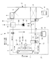
- a heat pump type vehicle air conditioning system 1 includes an HVAC unit (Heating Ventilation and Air Conditioning Unit) 2 and a heat pump type refrigerant circuit 3 capable of cooling and heating.
- the heat pump type vehicle air conditioning system 1 is applied to, for example, an electric powered vehicle (PHEV vehicle) equipped with an engine.
- PHEV vehicle electric powered vehicle
- the HVAC unit 2 switches and introduces either the inside air or the outside air from the vehicle compartment, and the blower 4 that feeds the pressure downstream, and the in-vehicle evaporator 6 disposed on the upstream side in the air flow path 5 connected to the blower 4
- the heater core 8 is disposed downstream of the heater core 8 and is capable of circulating a heat medium (brine) such as hot water through the heat medium circulation circuit 7, an amount of air flowing through the heater core 8, and an amount of air bypassed.
- the air mix damper 9 is provided to adjust the ratio and adjust the temperature of the temperature-controlled air blown into the vehicle compartment.
- the HVAC unit 2 is installed, for example, in an instrument panel on the vehicle compartment side, and selectively blows temperature-controlled air into the vehicle compartment from a plurality of outlets opened toward the vehicle compartment. It is.
- the exhaust heat from the engine of the PHEV vehicle in addition to the refrigerant / heat medium heat exchanger 16 on the heat pump refrigerant circuit 3 side described later.
- Exhaust heat recovery equipment such as exhaust heat from vehicle drive equipment such as a motor or an inverter, and heat source equipment such as a PTC heater are further provided, and various heat can be effectively used as a heating heat source.
- a heat pump type refrigerant circuit 3 switchable between a cooling cycle and a heating cycle includes an electric compressor 10 for compressing a refrigerant, an external heat exchanger (functions as a condenser during cooling and an evaporator during heating) 11, and a receiver.
- a closed cycle cooling refrigerant circuit (12), a first pressure reducing means 13 with an on-off valve function, and an in-vehicle evaporator 6 provided in the HVAC unit 2 are sequentially connected via a refrigerant pipe 14 in this order
- a cooling cycle) 15 is provided.
- the cooling refrigerant circuit 15 can be substantially equivalent to the refrigerant circuit used in the current vehicle air conditioning system applied to an engine drive type vehicle.
- the high temperature / high pressure refrigerant gas discharged from the motor compressor 10 and the heat medium circulating the heat medium circulation circuit 7 to the heater core 8 in the discharge pipe 14 A from the motor compressor 10 The refrigerant / heat medium heat exchanger 16 which exchanges heat is provided, and the three-way switching valve 17 is provided downstream thereof.
- the heating bypass circuit 18 is connected to the three-way switching valve 17, and the other end is connected to the receiver 12 so that the refrigerant condensed by the refrigerant / heat medium heat exchanger 16 is stored in the receiver 12 during heating. It is configured to be able to be introduced.
- a second pressure reducing means 19 with an open / close valve function is provided between the outlet refrigerant pipe 14C of the receiver 12 and the refrigerant outlet side (one end side of the heat exchanger 11 outside) of the heat exchanger 11 during cooling operation.
- a second circuit 20 for heating is connected, and a refrigerant inlet side (the other end side of the external heat exchanger 11) during cooling operation of the external heat exchanger 11 and a suction pipe 14F to the electric compressor 10 ,
- a third circuit 22 for heating provided with a solenoid valve 21 is connected.
- the third circuit 22 including the heat exchanger 11 and the solenoid valve 21 includes a discharge pipe 14A, a refrigerant pipe 14B (heating bypass circuit 18), an outlet refrigerant pipe 14C, a refrigerant pipe 14D (second circuit 20), and a refrigerant pipe in this order.
- a closed cycle heating refrigerant circuit (heating cycle) 23 connected via a suction pipe 14F (third circuit 22) and a suction pipe 14F can be configured.
- a fan 24 for circulating external air is attached to the heat exchanger 11 outside the vehicle.
- check valves 25 and 26 are integrally incorporated in the two refrigerant inlets to which the heating bypass circuit 18 from the three-way switching valve 17 and the refrigerant piping 14 from the external heat exchanger 11 are connected. It is considered as a receiver 12 with a fixed check valve. And, as the first pressure reducing means 13 and the second pressure reducing means 19 with the on-off valve function, it is possible to use a temperature type automatic expansion valve with a solenoid valve.
- the temperature type automatic expansion valve with a solenoid valve is provided on the refrigerant inlet side of the in-vehicle evaporator 6 or on the refrigerant inlet side of the external heat exchanger 11 functioning as the evaporator. It is integrated with the expansion valve.
- the electromagnetic valve is configured such that the movable iron core advances and retracts in the axial direction by energization of the electromagnetic coil, and the valve body opens and closes the inlet-side flow path.
- the temperature type automatic expansion valve senses the temperature and pressure of the refrigerant in the outlet side refrigerant passage 55 through which the refrigerant evaporated in the in-vehicle evaporator 6 or the external heat exchanger 11 flows, and the opening degree of the valve is adjusted.
- the solenoid valve and the temperature type automatic expansion valve may be configured by connecting independent and independent standard solenoid valves and temperature type automatic expansion valves in series.
- the above-mentioned temperature type automatic expansion valve with a solenoid valve opens the solenoid valve during operation using one or both of the in-vehicle evaporator 6 or the outside heat exchanger 11 functioning as an evaporator, and via the inlet side flow path
- the refrigerant adiabatically expanded by the temperature type automatic expansion valve is supplied to the in-vehicle evaporator 6 or the out-of-vehicle heat exchanger 11.
- the refrigerant flow rate can be automatically controlled by the temperature type automatic expansion valve so that the degree of refrigerant superheat at the outlet of each evaporator becomes constant.
- an electronic expansion valve may be used instead of the temperature type automatic expansion valve with a solenoid valve as the first pressure reducing means 13 and the second pressure reducing means 19 with an on-off valve function. It does not exclude use.
- the refrigerant compressed by the electric compressor 10 in the cooling mode, is the refrigerant / heat medium heat exchanger 16, the three-way switching valve 17, the condenser as shown by solid arrows.
- the cooling refrigerant circuit (cooling cycle) 15 that circulates through the external heat exchanger 11, the receiver 12, the first pressure reducing means 13 with the on-off valve function, and the in-vehicle evaporator 6 in this order and returning to the electric compressor 10 again. Circulate.
- the refrigerant compressed by the electric compressor 10 is the refrigerant / heat medium heat exchanger 16, the three-way switching valve 17, the heating bypass circuit 18, the receiver 12, the on-off valve as shown by the broken arrow.
- a second circuit 20 provided with a second pressure reducing means 19 with a function, an external heat exchanger 11 functioning as an evaporator, and a third circuit 22 provided with a solenoid valve 21 circulate in this order and return to the electric compressor 10 again.
- the heating refrigerant circuit (heating cycle) 23 circulates. Then, in the refrigerant / heat medium heat exchanger 16, a heat medium (brine) such as warm water circulating in the heat medium circulation circuit 7 is heated and supplied to the heater core 8.
- the high-temperature, high-pressure refrigerant gas compressed by the electric compressor 10 passes through the refrigerant / heat medium heat exchanger 16 and the three-way switching valve 17 by the discharge pipe 14A to function as a condenser.
- heat is exchanged with outside air ventilated by the fan 24 to condense and liquefy.
- the liquid refrigerant is introduced into the receiver 12 through the check valve 26 and temporarily stored since the solenoid valve of the temperature type automatic expansion valve with the solenoid valve constituting the second pressure reducing means 19 is closed. It is led to the first pressure reducing means 13 through the outlet refrigerant pipe 14C, and is decompressed to be in a gas-liquid two-phase state, and is supplied to the in-vehicle evaporator 6.
- the refrigerant evaporated by heat exchange with the inside air or the outside air blown from the blower 4 by the in-vehicle evaporator 6 is sucked into the electric compressor 10 through the suction pipe 14F and recompressed. The same cycle is repeated thereafter.
- the cooling refrigerant circuit 15 is not different from the cooling cycle of the current system used in an engine drive type vehicle, and can be shared as it is.
- the inside air or the outside air cooled by exchanging heat with the refrigerant in the process of passing through the in-vehicle evaporator 6 is blown out into the vehicle interior to provide cooling of the vehicle interior.
- the heat exchange in the refrigerant / heat medium heat exchanger 16 is interrupted by closing the heat medium circulation circuit 7 which circulates the heat medium to the refrigerant / heat medium heat exchanger 16 and the heater core 8. Can.
- the refrigerant compressed by the electric compressor 10 is led to the refrigerant / heat medium heat exchanger 16 through the discharge pipe 14A and exchanges heat with the heat medium circulating in the heat medium circulation circuit 7 to condense. It liquefies and heats the heat medium.
- the heat medium is circulated to the heater core 8 and provided for heating.
- the refrigerant condensed in the refrigerant / heat medium heat exchanger 16 is introduced into the receiver 12 through the three-way switching valve 17 and the heating bypass circuit 18 and temporarily stored, and then the solenoid valve constituting the first pressure reducing means 13 is provided.
- the check valve 26 maintains the closed state by the pressure difference, and the refrigerant does not flow from the external heat exchanger 11 side through the refrigerant pipe 14 to the receiver 12, and thus is supplied to the external heat exchanger 11.
- the refrigerant is heat-exchanged with the outside air ventilated by the fan 24 by the external heat exchanger 11 functioning as an evaporator, and is absorbed by the outside air and evaporated, and then the third circuit 22 equipped with the solenoid valve 21 and the suction pipe It is drawn into the electric compressor 10 through 14F and recompressed.
- this heating refrigerant circuit 23 can perform heat pump heating by using outside air as a heat source.
- the refrigerant / heat medium heat exchanger 16, the three-way switching valve 17, the heating bypass circuit 18, and the cooling refrigerant circuit 15 substantially equivalent to the cooling refrigerant circuit of the current system.
- a heat pump type refrigerant circuit 3 is configured by adding a second circuit 20 having a second pressure reducing means 19 and a third circuit 22 having a solenoid valve 21.
- an in-vehicle evaporator 6 on the upstream side and brine such as hot water on the downstream side By using the HVAC unit 2 similar to the HVAC of the current system in which the heater core 8 capable of circulating is arranged, two heats of the in-vehicle evaporator 6 and the external heat exchanger 11 (function as a condenser) in the cooling mode Cooling operation and heating operation by operating the exchanger and functioning two heat exchangers of the refrigerant / heat medium heat exchanger 16 and the external heat exchanger 11 (function as an evaporator) in the heating mode It can be carried out.
- the vehicle air conditioning system 1 can be configured, and simplification of the configuration, downsizing, and cost reduction can be achieved.
- the HVAC equivalent to the current system in which a heater core 8 of a type in which a heat medium including warm water is circulated downstream of the in-vehicle evaporator 6 is disposed as the HVAC unit 2 can be used as it is.
- Heat using a variety of heat sources such as recovering the exhaust heat of the engine, motor, inverter, etc. with a heat medium, or heating the heat medium with a PTC heater or the like to be a heating heat source, etc. Is possible.
- the refrigerant / heat medium heat exchanger 16 is provided in the discharge pipe 14A of the electric compressor 10 and the three-way switching valve 17 is provided downstream thereof, the three-way switching valve 17 can be installed on the CRFM 27 side, The mountability to a vehicle can be improved.
- the receiver 12 in which the heat pump type vehicle air conditioning system 1 is incorporated is the receiver 12 with a check valve in which the check valves 25 and 26 are incorporated in the refrigerant inlet, for cooling not used in the operation mode
- the refrigerant circuits 15 and 23 for heating can be shut off by the check valves 25 and 26 incorporated in the refrigerant inlets of the receiver 12, and the backflow of the refrigerant to the refrigerant circuits 15 and 23 can be prevented.
- the number of connecting parts such as flanges is reduced as compared with the case where receiver 12 and check valves 25 and 26 are separately provided in heat pump type refrigerant circuit 3
- the heat pump type refrigerant circuit 3 can be simplified and the cost can be reduced.
- the first pressure reducing means 13 and the second pressure reducing means 19 can be switched and used by using the on-off valve function, and at the time of heating mode, the outside heat exchanger 11 and the inside evaporator 6 can be used. It is possible to carry out combined driving.
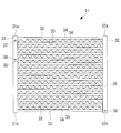
- the external heat exchanger 11 is a so-called multi-flow heat exchanger, and the tube 33 and the fins 34 are disposed between the two headers 31 and 32.
- the inflowing refrigerant branches into a plurality of tubes 33 and flows, and thereafter, the refrigerant flowing into each of the tubes 33 flows and joins in the other second header 32.
- the heat exchanger outside the vehicle 11 forms two sides where two headers 31 and 32 face each other, and has a substantially plate shape. Air is supplied from one surface side of the heat exchanger outside the vehicle 11, and the air is discharged from the other surface side on the back side of the one surface. When air passes through the heat exchanger 11, heat exchange is performed with the refrigerant flowing inside the tube 33.
- the external heat exchanger 11 is applied to, for example, the refrigerant circuit of the heat pump system as described above, and functions as a condenser during cooling operation and as an evaporator during heating operation. That is, when the external heat exchanger 11 functions as a condenser, the heat of the refrigerant flowing into the external heat exchanger 11 is released to the outside, and the refrigerant is cooled. At this time, the gaseous refrigerant flows into the external heat exchanger 11, and the refrigerant is liquefied in the external heat exchanger 11.
- the refrigerant flowing into the external heat exchanger 11 absorbs external heat, and the refrigerant is heated. At this time, a two-phase refrigerant of liquid and gas having passed through the second pressure reducing means 19 flows into the external heat exchanger 11, and the refrigerant is vaporized in the external heat exchanger 11.
- the heat exchanger outside the vehicle 11 is disposed adjacent to between the two tubes 33 and the two tubes 31 and 32 extending in the vertical direction, the tube 33 disposed between the two headers 31 and 32, and And the like.
- the tube 33 and the fins 34 for example, an alloy such as an aluminum alloy or a metal such as aluminum is used.
- Each of the headers 31 and 32 has a hollow cylindrical shape, and a plurality of tubes 33 are fixed at substantially equal intervals in the vertical direction.
- the insides of the headers 31 and 32 and the inside of the tube 33 communicate with each other, and the refrigerant flows through the insides of both.
- the two headers 31 and 32 are a first header 31 and a second header 32, respectively.
- the refrigerant is transferred from the first header 31 to the second header 32, and then from the second header 32 to the first header 31.
- the first header 31 is an inlet side into which the refrigerant flows when the external heat exchanger 11 functions as a condenser, and is an outlet side from which the refrigerant flows out when it functions as an evaporator.
- the second header 32 is an outlet side from which the refrigerant flows out when the external heat exchanger 11 functions as a condenser, and is an inlet side into which the refrigerant flows when functioning as an evaporator.
- the tube 33 has a flat shape, and a plurality of flow passages extending in the longitudinal direction of the tube 33 are formed therein.
- the plurality of flow passages are arranged in parallel in the width direction of the tube 33.
- One end of the tube 33 is connected to the first header 31, and the other end of the tube 33 is connected to the second header 32.
- a plurality of thin plates are arranged in the fins 34, and a gap is provided between the plurality of thin plates so that air can flow from one surface of the external heat exchanger 11 to the other surface.
- the fins 34 are in contact with the tube 33 at upper and lower portions, and the heat of the refrigerant flowing through the tube 33 is transferred.
- the refrigerant flowing from the opening of the first header 31 flows downward from above the first header 31. It flows into the flow passage of each tube 33 connected to the 1 header 31.
- the refrigerant flowing into the flow passage of the tube 33 flows toward the second header 32 and flows into the second header 32.
- the refrigerant flowing into the second header 32 flows downward from above and flows out of the opening of the second header 32.
- the partition plate 35 may be provided inside the headers 31 and 32, or the partition plate may not be provided. If no divider plate is provided, the headers 31, 32 communicate with all the tubes 33 connected to the headers 31, 32. Therefore, it is difficult for the refrigerant flowing into the headers 31 and 32 to efficiently circulate the refrigerant, but the refrigerant can flow to all the tubes 33.
- each of the headers 31 and 32 When one partition plate is provided in each of the first header 31 and the second header 32, the inside of each of the headers 31 and 32 is between the uppermost surfaces 31 a and 32 a of the headers 31 and 32 and the partition plate 35 and the partition plate 35 And the lowermost surfaces 31b and 32b of the headers 31 and 32, respectively.
- the divided space inside the headers 31 and 32 communicates with the tube 33 connected in the divided space. Therefore, the refrigerant which has flowed into each divided space of the headers 31 and 32 flows only to the tube 33 connected to the divided space. Thereby, the refrigerant is transferred from the first header 31 to the second header 32, then from the second header 32 to the first header 31, and further from the first header 31 to the second header 32 in the external heat exchanger 11. Can be flowed back.
- partition plates 35 may be provided in one header 31 and 32, and division space may be formed between the partition plates 35 which the partition plate 35 adjoins. In this case, the refrigerant reciprocates in the outside heat exchanger 11 two or more times. Further, the partition plate 35 may be provided only on the first header 31, and the partition plate 35 may not be provided on the second header 32. In this case, the refrigerant reciprocates only within the heat exchanger 11 outside the vehicle.
- the openings 36, 37, 38 provided in the first header 31 and the second header 32 that is, the refrigerant inlet and the refrigerant outlet will be described.
- the first opening 36 is formed at a lower position of the total height of the divided space divided by the uppermost surface 31 a of the first header 31 and the partition plate 35.
- the first opening 36 is desirably provided in the vicinity of the partition plate 35, and provided between the partition plate 35 and a position about one third of the height of the divided space from the partition plate 35. It may be done.
- the first opening portion 36 serves as a refrigerant outlet portion through which the refrigerant flows when the external heat exchanger 11 functions as an evaporator.
- the second opening 37 is formed at a position higher than the first opening 36 and in a divided space divided by the uppermost surface of the first header 31 and the partition plate 35.
- the second opening 37 serves as a refrigerant inlet portion into which the refrigerant flows when the external heat exchanger 11 functions as a condenser.
- first opening 36 and the second opening 37 are separately provided in the first header 31, when connecting the piping to the heat exchanger outside the vehicle 11, when the opening is made common and the piping is branched In comparison, piping work becomes easier.
- a third opening 38 is formed in the second header 32 near the lowermost surface of the second header 32.
- the third opening 38 is a refrigerant outlet where the refrigerant flows out when the external heat exchanger 11 functions as a condenser, and is a refrigerant inlet where the refrigerant flows when it functions as an evaporator.
- the refrigerant flows from the third opening 38, and the refrigerant flows from the lower portion to the upper portion of the external heat exchanger 11.
- the liquefied refrigerant is always present in the lower part of the heat exchanger outside the vehicle 11 and suppresses an increase in pressure loss inside the heat exchanger outside the vehicle 11 compared to the case where the refrigerant flows from the upper part to the lower part it can.
- the first opening 36 serving as a refrigerant outlet from which the refrigerant flows out is formed at a low position of the divided space of the first header 31, when the external heat exchanger 11 functions as an evaporator, When all the refrigerant reaching the outlet of the exchanger 11 can not be gasified, the liquid refrigerant can be discharged to the outside through the first opening 36 at the height of the first opening 36. The amount of liquid refrigerant accumulated in the first header 31 can be suppressed.
- the heat exchanger 11 functions as an evaporator
- the refrigerant is liquefied in the vicinity of the second opening 37 higher than the first opening 36 and the piping connected to the second opening 37
- the refrigerant can flow out from the first opening 36 formed at the lower position of the divided space of the first header 31.
- the first opening 36 serving as the refrigerant outlet from which the refrigerant flows out when functioning as the evaporator functions as the condenser. It is formed separately from the second opening 37 where the refrigerant flows.
- the first opening 36 is formed at a lower position than the second opening 37 and at a lower position of the divided space of the first header 31.
- the refrigerant outlet when functioning as an evaporator and the mounting position of the refrigerant inlet when functioning as a condenser are It was the top.
- the surplus refrigerant is accumulated to a position where the top of the header of the heat exchanger outside the vehicle 11 is reached.
- the amount of surplus refrigerant increases.
- the amount of surplus liquid refrigerant accumulated in the first header 31 can be suppressed.
- the mounting positions of the refrigerant outlet when functioning as an evaporator and the refrigerant inlet when functioning as a condenser are It was the same height or only one opening was used to share both.
- the refrigerant liquefied by the refrigerant inlet used when functioning as a condenser, and the pipe connected to the refrigerant inlet for the condenser has the same height as that of the refrigerant outlet. It is not discharged until it reaches the end, or it is not discharged from the outside heat exchanger 11 at all.
- the first opening 36 is formed at a lower position than the second opening 37 and at a lower position of the divided space of the first header 31, the vicinity of the second opening 37 or Even if the refrigerant is liquefied by the pipe connected to the second opening 37, the refrigerant can flow out from the first opening 36.
Abstract
暖房運転時に室外熱交換器で溜まり込んでいる冷媒量を低減し、暖房運転時の適正冷媒量を減らすことが可能な熱交換器及びヒートポンプシステムを提供することを目的とする。車外熱交換器(11)は、中空状の第1ヘッダー(31)と、第1ヘッダー(31)に対向して設けられ、中空状の第2ヘッダー(32)と、第1ヘッダー(31)と第2ヘッダー(32)の間に設けられ、第1ヘッダー(31)と第2ヘッダー(32)と連通する複数のチューブ(33)とを備え、第1ヘッダー(31)には、第1ヘッダー(31)の内部を区切る仕切板(35)が設けられ、第1ヘッダー(31)には、第1ヘッダー(31)の上端部と仕切板(35)の間において仕切板(35)側に第1開口部(36)が形成され、蒸発器として機能するとき、冷媒は第1ヘッダー(31)又は第2ヘッダー(32)の下部側から供給され、第1開口部(36)が冷媒の流出口となる。
Description
本発明は、熱交換器及びヒートポンプシステムに関するものである。
電気自動車(EV車)、エンジンを搭載している電動車両(HEV車、PHEV車)等に用いられる車両用空調システムでは、エンジン冷却水等の燃焼排熱を利用した暖房運転を行うことができない。このため、電動圧縮機を用いたヒートポンプ方式の空調システムが考えられている。
下記の特許文献1では、車室外蒸発器と車室外凝縮器が別に設けられ、通常暖房運転用の冷凍サイクルには、車室外蒸発器が接続され、冷房運転用の冷凍サイクルには、車室外凝縮器が接続される構成が開示されている。
特許文献1で開示された技術と異なり、室外熱交換器が蒸発器と凝縮器の両方の機能を有し、室外熱交換器が、暖房運転時に蒸発器として機能し、冷房運転時に凝縮器として機能することで、ヒートポンプシステムの構成を簡便にできる。
上記の特許文献2では、ヒートポンプシステムに適用され、蒸発器及び凝縮器の双方の機能を有する室外熱交換器に関する技術が開示されている。しかし、特許文献2で開示された室外熱交換器では、複雑な冷媒の流し方が行われており、室外熱交換器に接続する配管や追加のバルブが必要である。
発明者らは、蒸発器と凝縮器の両方の機能を有する室外熱交換器を用いるヒートポンプシステムにおいて、暖房運転時の適正冷媒量と、冷房運転時の適正冷媒量が異なり、暖房運転時の適正冷媒量は、冷房運転時に比べて多いという知見を得た。
従来、ヒートポンプシステムでは、最大冷房時の評価から適正冷媒量とレシーバ容量を選定している。これに対し、蒸発器と凝縮器の両方の機能を有する室外熱交換器を用いるヒートポンプシステムを適用する場合、暖房運転時の適正冷媒量を考慮する必要があるため、従来のヒートポンプシステムに比べて、冷媒量のバッファ機能を有するレシーバ容量を拡大することが考えられる。しかし、ヒートポンプシステム全体の容量が大きくなったり、レシーバ容量の拡大によってコストが増加するという問題が生じる。
暖房運転時にレシーバ以外の構成要素で冷媒が溜まっており、暖房運転時の適正冷媒量と、冷房運転時の適正冷媒量の差を低減するには、この溜まり込み量を低減する必要がある。
本発明は、このような事情に鑑みてなされたものであって、暖房運転時に室外熱交換器で溜まり込んでいる冷媒量を低減し、暖房運転時の適正冷媒量を減らすことが可能な熱交換器及びヒートポンプシステムを提供することを目的とする。
本発明の第1態様に係る熱交換器は、中空状の第1ヘッダーと、前記第1ヘッダーに対向して設けられ、中空状の第2ヘッダーと、前記第1ヘッダーと前記第2ヘッダーの間に設けられ、前記第1ヘッダーと前記第2ヘッダーと連通する複数のチューブとを備え、前記第1ヘッダーには、前記第1ヘッダーの内部を区切る仕切板が設けられ、前記第1ヘッダーには、前記第1ヘッダーの上端部と前記仕切板の間において前記仕切板側に第1開口部が形成され、蒸発器として機能するとき、冷媒は前記第1ヘッダー又は前記第2ヘッダーの下部側から供給され、前記第1開口部が前記冷媒の流出口となる。
この構成によれば、冷媒は、第1ヘッダーとチューブと第2ヘッダーとを流通可能である。蒸発器として機能するとき、冷媒は、第1ヘッダー又は第2ヘッダーの下部側から供給され、その後、第1ヘッダーの上端部と仕切板の間において、仕切板側に形成された第1開口部から流出する。第1開口部が仕切板側に形成されることから、第1ヘッダーの上端部まで液化した冷媒が溜まることなく、第1開口部が形成された高さで、第1開口部を介して液化した冷媒を流出させることができる。その結果、液冷媒が第1ヘッダー内部で溜まり込む量を抑制できる。
本発明の第1態様において、前記第1ヘッダーには、前記第1開口部よりも前記第1ヘッダーの上端部側において、第2開口部が形成され、凝縮器として機能するとき、冷媒は、前記第2開口部から供給され、前記第1ヘッダー又は前記第2ヘッダーの下部側へ流れる。
この構成によれば、凝縮器として機能するとき、冷媒は、第2開口部から供給され、その後、第1ヘッダー又は第2ヘッダーの下部側へ流れる。第2開口部は、第1開口部よりも第1ヘッダーの上端部側に形成されることから、蒸発器として機能する場合において、第2開口部付近や、第2開口部に接続された配管で冷媒が液化したとしても、第1開口部から冷媒を排出することができる。
本発明の第2態様に係るヒートポンプシステムは、上述の熱交換器と、前記熱交換器が接続され、前記熱交換器が蒸発器として機能するとき、冷媒が流通する第1回路と、前記熱交換器が接続され、前記熱交換器が凝縮器として機能するとき、冷媒が流通する第2回路とを備える。
本発明の第2態様において、ヒートポンプシステムは、前記熱交換器、前記第1回路及び前記第2回路を備え、車両用空調システムとして適用される。
本発明によれば、暖房運転時に室外熱交換器で溜まり込んでいる冷媒量を低減し、暖房運転時の適正冷媒量を減らすことができる。
以下に、本発明の一実施形態に係るヒートポンプ式車両用空調システム1及び車外熱交換器11について、図面を参照して説明する。
まず、本発明の一実施形態に係るヒートポンプ式車両用空調システム1について、図1を用いて説明する。
本実施形態に係るヒートポンプ式車両用空調システム1は、HVACユニット(Heating Ventilation and Air Conditioning Unit)2と、冷暖房が可能なヒートポンプ式冷媒回路3とを備えている。ヒートポンプ式車両用空調システム1は、例えば、エンジンを搭載している電動車両(PHEV車)に適用される。
まず、本発明の一実施形態に係るヒートポンプ式車両用空調システム1について、図1を用いて説明する。
本実施形態に係るヒートポンプ式車両用空調システム1は、HVACユニット(Heating Ventilation and Air Conditioning Unit)2と、冷暖房が可能なヒートポンプ式冷媒回路3とを備えている。ヒートポンプ式車両用空調システム1は、例えば、エンジンを搭載している電動車両(PHEV車)に適用される。
HVACユニット2は、車室内からの内気又は外気のいずれかを切替え導入し、下流側に圧送するブロア4と、ブロア4に連なる空気流路5中の上流側に配設される車内蒸発器6と、その下流側に配設され、温水等の熱媒体(ブライン)が熱媒体循環回路7を介して循環可能とされているヒータコア8と、ヒータコア8を流通する空気量とバイパスする空気量の割合を調整して車室内に吹き出される温調風の温度を調整するエアミックスダンパ9とを備えている。
このHVACユニット2は、例えば、車室側のインストルメントパネル内に設置され、温調風を車室内に向けて開口されている複数の吹出し口から選択的に車室内へと吹き出す構成としたものである。
なお、ヒータコア8に温水等の熱媒体を循環する熱媒体循環回路7には、後述するヒートポンプ式冷媒回路3側の冷媒/熱媒体熱交換器16の他に、PHEV車のエンジンからの排熱、モータあるいはインバータ等の車両駆動機器からの排熱等の排熱回収機器、更にはPTCヒータ等の熱源機器が設けられ、多様な熱が暖房用熱源として有効に利用できる構成とされている。
冷房サイクルと暖房サイクルとに切替え可能なヒートポンプ式冷媒回路3は、冷媒を圧縮する電動圧縮機10と、車外熱交換器(冷房時には凝縮器、暖房時には蒸発器として機能する。)11と、レシーバ12と、開閉弁機能付きの第1減圧手段13と、HVACユニット2内に設けられている車内蒸発器6とがこの順に冷媒配管14を介して接続されている閉サイクルの冷房用冷媒回路(冷房サイクル)15を備えている。この冷房用冷媒回路15は、エンジン駆動方式の車両に適用されている現行の車両用空調システムに用いられている冷媒回路とほぼ同等のものとすることができる。
また、ヒートポンプ式冷媒回路3には、電動圧縮機10からの吐出配管14Aに、電動圧縮機10から吐出された高温高圧冷媒ガスと、ヒータコア8への熱媒体循環回路7を循環する熱媒体とを熱交換する冷媒/熱媒体熱交換器16が設けられているとともに、その下流側に三方切替え弁17が設けられている。この三方切替え弁17には、暖房用バイパス回路18が接続され、その他端がレシーバ12に接続されることにより、暖房時、冷媒/熱媒体熱交換器16で凝縮された冷媒をレシーバ12内に導入できる構成とされている。
また、レシーバ12の出口冷媒配管14Cと、車外熱交換器11の冷房運転時の冷媒出口側(車外熱交換器11の一端側)との間に、開閉弁機能付きの第2減圧手段19を備えた暖房用の第2回路20が接続されるとともに、車外熱交換器11の冷房運転時の冷媒入口側(車外熱交換器11の他端側)と、電動圧縮機10への吸入配管14Fとの間に、電磁弁21を備えた暖房用の第3回路22が接続されている。
これによって、電動圧縮機10、冷媒/熱媒体熱交換器16、三方切替え弁17、暖房用バイパス回路18、レシーバ12、開閉弁機能付きの第2減圧手段19を備えた第2回路20、車外熱交換器11及び電磁弁21を備えた第3回路22がこの順に吐出配管14A,冷媒配管14B(暖房用バイパス回路18),出口冷媒配管14C,冷媒配管14D(第2回路20),冷媒配管14E(第3回路22),吸入配管14Fを介して接続される閉サイクルの暖房用冷媒回路(暖房サイクル)23が構成可能とされている。なお、車外熱交換器11に対しては、外気を流通させるためのファン24が付設されている。
更に、上記レシーバ12は、三方切替え弁17からの暖房用バイパス回路18及び車外熱交換器11からの冷媒配管14が接続される2つの冷媒流入口に逆止弁25,26が一体的に組み込まれた逆止弁付きレシーバ12とされている。及び開閉弁機能付きの第1減圧手段13及び第2減圧手段19として、電磁弁付き温度式自動膨張弁を用いることができる。電磁弁付き温度式自動膨張弁は、車内蒸発器6の冷媒入口側及び、又は、蒸発器として機能する車外熱交換器11の冷媒入口側に設けられるものであり、電磁弁と、温度式自動膨張弁とが一体化されたものである。電磁弁は、電磁コイルへの通電により可動鉄心が軸方向に進退し、弁体が入口側流路を開閉する構成とされている。温度式自動膨張弁は、車内蒸発器6又は車外熱交換器11で蒸発した冷媒が流通する出口側冷媒流路55内の冷媒の温度と圧力とを感知して、弁の開度が調整される構成とされている。なお、電磁弁と温度式自動膨張弁は、独立した個別の標準的な電磁弁、温度式自動膨張弁を直列に接続して構成したものとしてもよい。
上記の電磁弁付き温度式自動膨張弁は、車内蒸発器6又は蒸発器として機能する車外熱交換器11の一方又は双方を使った運転時、電磁弁を開とし、入口側流路を介して温度式自動膨張弁で断熱膨張された冷媒を車内蒸発器6又は車外熱交換器11に供給する。電磁弁付き温度式自動膨張弁を用いれば、各蒸発器出口の冷媒過熱度が一定となるように温度式自動膨張弁で冷媒流量を自動制御することができる。これによって、冷媒圧力検出手段及び冷媒温度検出手段を必要とする電子膨張弁を使用したシステムに比べ、構成を簡素化し、低コスト化することができる。
なお、本発明おいては、開閉弁機能付きの第1減圧手段13及び第2減圧手段19として、電磁弁付き温度式自動膨張弁に代え、電子膨張弁を用いてもよく、電子膨張弁の使用を除外するものではない。
上記のヒートポンプ式車両用空調システム1において、冷房モード時、電動圧縮機10により圧縮された冷媒は、実線矢印で示されるように、冷媒/熱媒体熱交換器16、三方切替え弁17、凝縮器として機能する車外熱交換器11、レシーバ12、開閉弁機能付きの第1減圧手段13、車内蒸発器6をこの順に流通し、再び電動圧縮機10に戻る冷房用冷媒回路(冷房サイクル)15内を循環する。
一方、暖房モード時、電動圧縮機10により圧縮された冷媒は、破線矢印で示されるように、冷媒/熱媒体熱交換器16、三方切替え弁17、暖房用バイパス回路18、レシーバ12、開閉弁機能付きの第2減圧手段19を備えた第2回路20、蒸発器として機能する車外熱交換器11、電磁弁21を備えた第3回路22をこの順に流通し、再び電動圧縮機10に戻る暖房用冷媒回路(暖房サイクル)23内を循環する。そして、冷媒/熱媒体熱交換器16において、熱媒体循環回路7内を循環する温水等の熱媒体(ブライン)を加熱し、ヒータコア8に供給する。
以上に説明の構成により、本実施形態によれば、以下の作用効果を奏する。
まず、冷房モード時、電動圧縮機10で圧縮された高温高圧の冷媒ガスは、吐出配管14Aにより冷媒/熱媒体熱交換器16、三方切替え弁17を経て凝縮器として機能する車外熱交換器11に導かれ、ここでファン24により通風される外気と熱交換されて凝縮液化される。この液冷媒は、第2減圧手段19を構成する電磁弁付き温度式自動膨張弁の電磁弁が閉とされているため、逆止弁26を経てレシーバ12に導入され、いったん貯留された後、出口冷媒配管14Cを経て第1減圧手段13に導かれ、減圧されて気液二相状態となり、車内蒸発器6に供給される。
まず、冷房モード時、電動圧縮機10で圧縮された高温高圧の冷媒ガスは、吐出配管14Aにより冷媒/熱媒体熱交換器16、三方切替え弁17を経て凝縮器として機能する車外熱交換器11に導かれ、ここでファン24により通風される外気と熱交換されて凝縮液化される。この液冷媒は、第2減圧手段19を構成する電磁弁付き温度式自動膨張弁の電磁弁が閉とされているため、逆止弁26を経てレシーバ12に導入され、いったん貯留された後、出口冷媒配管14Cを経て第1減圧手段13に導かれ、減圧されて気液二相状態となり、車内蒸発器6に供給される。
車内蒸発器6でブロア4から送風されてくる内気又は外気と熱交換されて蒸発した冷媒は、吸入配管14Fを経て電動圧縮機10に吸入され、再圧縮される。以下、同様のサイクルが繰り返されることになる。この冷房用冷媒回路15は、エンジン駆動方式の車両に用いられている現行システムの冷房サイクルと何ら変わるものではなく、そのまま共用化することができる。車内蒸発器6を通過する過程で冷媒と熱交換することにより冷却された内気又は外気は、車室内に吹き出されることによって、車室内の冷房に供される。
なお、冷房モードの間、冷媒/熱媒体熱交換器16及びヒータコア8に熱媒体を循環する熱媒体循環回路7を閉じることにより、冷媒/熱媒体熱交換器16での熱交換を中断させることができる。
なお、冷房モードの間、冷媒/熱媒体熱交換器16及びヒータコア8に熱媒体を循環する熱媒体循環回路7を閉じることにより、冷媒/熱媒体熱交換器16での熱交換を中断させることができる。
また、暖房モード時、電動圧縮機10で圧縮された冷媒は、吐出配管14Aを経て冷媒/熱媒体熱交換器16に導かれ、熱媒体循環回路7を循環する熱媒体と熱交換して凝縮液化し、熱媒体を加熱する。この熱媒体は、ヒータコア8に循環され、暖房に供されることになる。冷媒/熱媒体熱交換器16で凝縮された冷媒は、三方切替え弁17、暖房用バイパス回路18を経てレシーバ12に導入され、いったん貯留された後、第1減圧手段13を構成する電磁弁付き温度式自動膨張弁の電磁弁が閉とされているため、出口冷媒配管14C、第2回路20を経て第2減圧手段19に導かれ、ここで減圧された気液二相状態となり、車外熱交換器11に供給される。
この際、車外熱交換器11とレシーバ12間を接続する冷媒配管14内の冷媒は、逆止弁26に対して順方向となるが、冷媒配管14内は低圧、レシーバ12内は高圧であることから、その圧力差で逆止弁26は閉状態を維持し、冷媒が車外熱交換器11側から冷媒配管14を経てレシーバ12に流れることはなく、従って、車外熱交換器11に供給された冷媒は、蒸発器として機能する車外熱交換器11でファン24により通風される外気と熱交換され、外気から吸熱して蒸発された後、電磁弁21を備えた第3回路22、吸入配管14Fを経て電動圧縮機10に吸入され、再圧縮される。以下、同様のサイクルが繰り返されることになり、この暖房用冷媒回路23により、外気を熱源にしてヒートポンプ暖房を行うことができる。
斯くして、本実施形態によると、現行システムの冷房用冷媒回路とほぼ同等の冷房用冷媒回路15に対して、冷媒/熱媒体熱交換器16、三方切替え弁17、暖房用バイパス回路18、第2減圧手段19を有する第2回路20及び電磁弁21を有する第3回路22を追加してヒートポンプ式冷媒回路3を構成し、更に上流側に車内蒸発器6、下流側に温水等のブラインが循環可能なヒータコア8を配設した現行システムのHVACと同様のHVACユニット2を用いることにより、冷房モード時、車内蒸発器6及び車外熱交換器11(凝縮器として機能)の2枚の熱交換器を機能させ、暖房モード時、冷媒/熱媒体熱交換器16及び車外熱交換器11(蒸発器として機能)の2枚の熱交換器を機能させることにより、冷房運転及び暖房運転を行わせることができる。
従って、電動圧縮機10の仕事量に見合った最大限の能力で効率のよい冷房運転、暖房運転を行い、冷暖房能力を向上させることができるとともに、最小限の暖房用機器を追加してヒートポンプ式車両用空調システム1を構成することができ、構成の簡素化、小型化、低コスト化を図ることができる。
また、HVACユニット2として、車内蒸発器6の下流側に温水を含む熱媒体が循環されるタイプのヒータコア8を配置した現行システムと同等のHVACをそのまま流用することができるため、車両の駆動機器であるエンジン、モータ、インバータ等の排熱を熱媒体により回収し、あるいはその熱媒体をPTCヒータ等により加熱して暖房用熱源とすることができる等、多様な熱源を利用して暖房することが可能となる。更に、冷媒/熱媒体熱交換器16を電動圧縮機10の吐出配管14Aに設け、その下流側に三方切替え弁17を設けているため、三方切替え弁17をCRFM27側に設置することができ、車両への搭載性を向上させることができる。
更に、上記ヒートポンプ式車両用空調システム1の組み込まれるレシーバ12が、冷媒流入口に逆止弁25,26が組み込まれた逆止弁付きレシーバ12とされているため、運転モードにより使用されない冷房用又は暖房用の冷媒回路15,23をレシーバ12の冷媒流入口に組み込まれた逆止弁25,26で遮断し、それら冷媒回路15,23への冷媒の逆流を阻止することができる。従って、使用されない冷媒回路15,23への冷媒流れを防止できるとともに、レシーバ12、逆止弁25,26を個別にヒートポンプ式冷媒回路3に設けたものに比べ、フランジ等の接続用部品を低減し、ヒートポンプ式冷媒回路3の簡素化、低コスト化を図ることができる。
従って、運転モードに応じ、その開閉弁機能を用いて第1減圧手段13及び第2減圧手段19を切替え使用することができるとともに、暖房モード時において、車外熱交換器11及び車内蒸発器6を併用した運転を行うことができる。
以下、図2及び図3を参照して、本実施形態に係るヒートポンプ式車両用空調システム1に適用される車外熱交換器11について説明する。
本実施形態に係る車外熱交換器11は、いわゆるマルチフロー型の熱交換器であり、2本のヘッダー31,32間にチューブ33とフィン34が配置されており、一方の第1ヘッダー31に流入した冷媒が、複数のチューブ33に分岐して流れ、その後、各チューブ33に分岐して流れた冷媒は、他方の第2ヘッダー32で合流する。
車外熱交換器11は、2本のヘッダー31,32が対向する2辺を構成し、ほぼ板形状を有している。車外熱交換器11の一面側から空気が供給され、一面に対し裏側の他面側から空気が排出される。空気が車外熱交換器11を通過するとき、チューブ33内部を流れる冷媒と熱交換が行われる。
車外熱交換器11は、上述したような、例えば、ヒートポンプシステムの冷媒回路に適用され、かつ、冷房運転時には、凝縮器として機能し、暖房運転時には、蒸発器として機能する。すなわち、車外熱交換器11が凝縮器として機能するとき、車外熱交換器11に流入する冷媒が有する熱が、外部へ放出され、冷媒が冷却される。このとき、車外熱交換器11には気体の冷媒が流入し、車外熱交換器11内で冷媒が液化する。
一方、車外熱交換器11が蒸発器として機能するとき、車外熱交換器11に流入する冷媒は、外部の熱を吸収し、冷媒が加熱される。このとき、車外熱交換器11には第2減圧手段19を通過した液体と気体の二相冷媒が流入し、車外熱交換器11内で冷媒が気化する。
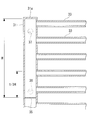
車外熱交換器11は、上下方向に延設される2本のヘッダー31,32と、2本のヘッダー31,32間に配置されるチューブ33と、2本のチューブ33間に隣接して配置されるフィン34などから構成される。
ヘッダー31,32、チューブ33及びフィン34には、例えばアルミニウム合金等の合金、アルミニウム等の金属が用いられる。
ヘッダー31,32、チューブ33及びフィン34には、例えばアルミニウム合金等の合金、アルミニウム等の金属が用いられる。
ヘッダー31,32は、それぞれ、中空の筒形状であって、複数のチューブ33が上下方向にほぼ等間隔で固定される。ヘッダー31,32内部とチューブ33内部は連通し、両者の内部を冷媒が流通する。
2本のヘッダー31,32は、それぞれ、第1ヘッダー31と、第2ヘッダー32である。仕切板が第1ヘッダー31と第2ヘッダー32の内部に1枚ずつ設けられる場合、冷媒は、第1ヘッダー31から第2ヘッダー32へ、その後、第2ヘッダー32から第1ヘッダー31へ、さらに、第1ヘッダー31から第2ヘッダー32へと、車外熱交換器11内を折り返して流れる。
第1ヘッダー31は、車外熱交換器11が凝縮器として機能するとき、冷媒が流入する入口側となり、蒸発器として機能するとき、冷媒が流出する出口側となる。第2ヘッダー32は、車外熱交換器11が凝縮器として機能するとき、冷媒が流出する出口側となり、蒸発器として機能するとき、冷媒が流入する入口側となる。
チューブ33は、扁平形状で、内部にはチューブ33の長手方向に延びる複数の流通路が形成される。複数の流通路は、チューブ33の幅方向に並列配置される。チューブ33の一端は、第1ヘッダー31と接続され、チューブ33の他端は、第2ヘッダー32と接続される。
フィン34は、薄板が複数配置されたものであり、車外熱交換器11の一面から他面側に空気が流通できるように複数の薄板間には隙間が設けられている。フィン34は、上部と下部でチューブ33と接しており、チューブ33を流れる冷媒の熱が伝達される。
本実施形態に係るマルチフロー型車外熱交換器11は、凝縮器として機能するとき、第1ヘッダー31の開口部から流入した冷媒は、第1ヘッダー31の上方から下方に向かって流れつつ、第1ヘッダー31に接続された各チューブ33の流通路に流入する。チューブ33の流通路に流入した冷媒は、第2ヘッダー32に向かって流れ、第2ヘッダー32に流入する。第2ヘッダー32に流入した冷媒は、上方から下方に向かって流れて、第2ヘッダー32の開口部から流出する。
次に、本実施形態に係る車外熱交換器11のヘッダー31,32について詳細に説明する。
ヘッダー31,32の内部には、上述したとおり、仕切板35が設けられてもよいし、仕切板が設けられなくてもよい。仕切板が設けられない場合、ヘッダー31,32は、ヘッダー31,32に接続された全てのチューブ33に対して連通する。そのため、ヘッダー31,32に流入した冷媒は、冷媒を効率良く流通させることが難しいが、全てのチューブ33に対して流通可能である。
ヘッダー31,32の内部には、上述したとおり、仕切板35が設けられてもよいし、仕切板が設けられなくてもよい。仕切板が設けられない場合、ヘッダー31,32は、ヘッダー31,32に接続された全てのチューブ33に対して連通する。そのため、ヘッダー31,32に流入した冷媒は、冷媒を効率良く流通させることが難しいが、全てのチューブ33に対して流通可能である。
仕切板が第1ヘッダー31と第2ヘッダー32に1枚ずつ設けられる場合、各ヘッダー31,32の内部は、ヘッダー31,32の最上面31a,32aと仕切板35間、及び、仕切板35とヘッダー31,32の最下面31b,32bに分割される。そして、ヘッダー31,32内部の分割空間は、その分割空間において接続されたチューブ33に対して連通する。そのため、ヘッダー31,32の各分割空間に流入した冷媒は、その分割空間に接続されたチューブ33に対してのみ流通する。これにより、冷媒を、第1ヘッダー31から第2ヘッダー32へ、その後、第2ヘッダー32から第1ヘッダー31へ、さらに、第1ヘッダー31から第2ヘッダー32へと、車外熱交換器11内を折り返して流すことができる。
なお、1本のヘッダー31,32に2枚以上の仕切板35が設けられて、仕切板35が隣接する仕切板35間に分割空間が形成されてもよい。この場合、冷媒は、車外熱交換器11内を2往復以上する。また、第1ヘッダー31のみに仕切板35が設けられ、第2ヘッダー32には仕切板35が設けられなくてもよい。この場合、冷媒は、車外熱交換器11内を1往復のみする。
次に、第1ヘッダー31と第2ヘッダー32に設けられる開口部36,37,38、すなわち、冷媒入口部、冷媒出口部について説明する。
第1ヘッダー31には、第1ヘッダー31の最上面31aと仕切板35で区切られる分割空間の全高さのうち、低い位置に第1開口部36が形成される。例えば、第1開口部36は、仕切板35の近傍に設けられることが望ましく、仕切板35と、仕切板35から分割空間の全高さのうち1/3の高さ程度の位置の間に設けられてもよい。
第1開口部36は、車外熱交換器11が蒸発器として機能するとき、冷媒が流出する冷媒出口部となる。
第1開口部36は、車外熱交換器11が蒸発器として機能するとき、冷媒が流出する冷媒出口部となる。
また、第1ヘッダー31には、第1開口部36よりも高い位置であって、第1ヘッダー31の最上面と仕切板35で区切られる分割空間において、第2開口部37が形成される。
第2開口部37は、車外熱交換器11が凝縮器として機能するとき、冷媒が流入する冷媒入口部となる。
第2開口部37は、車外熱交換器11が凝縮器として機能するとき、冷媒が流入する冷媒入口部となる。
第1開口部36と第2開口部37は、第1ヘッダー31において別々に設けられることから、車外熱交換器11に配管を接続する際、開口部が共通化されて配管を分岐させる場合に比べて、配管作業が容易になる。
第2ヘッダー32には、第2ヘッダー32の最下面の近傍に第3開口部38が形成される。
第3開口部38は、車外熱交換器11が凝縮器として機能するとき、冷媒が流出する冷媒出口部となり、蒸発器として機能するとき、冷媒が流入する冷媒入口部となる。
第3開口部38は、車外熱交換器11が凝縮器として機能するとき、冷媒が流出する冷媒出口部となり、蒸発器として機能するとき、冷媒が流入する冷媒入口部となる。
車外熱交換器11が蒸発器として機能するとき、冷媒は第3開口部38から流入して、車外熱交換器11の下部から上部に向けて冷媒が流れる。これにより、液化した冷媒は、常に車外熱交換器11の下部に溜まった状態で存在し、上部から下部へ冷媒を流す場合に比べて、車外熱交換器11内部での圧力損失の増加を抑制できる。
また、冷媒が流出する冷媒出口部となる第1開口部36が第1ヘッダー31の分割空間の低い位置に形成されることから、車外熱交換器11が蒸発器として機能する場合において、車外熱交換器11の出口に至る冷媒の全てをガス化できなかったとき、第1開口部36の高さで、第1開口部36を介して液冷媒を外部に排出できる。液冷媒が第1ヘッダー31内部で溜まり込む量を抑制できる。
さらに、車外熱交換器11が蒸発器として機能する場合において、第1開口部36よりも高い位置の第2開口部37付近や、第2開口部37に接続された配管で冷媒が液化したとしても、第1ヘッダー31の分割空間の低い位置に形成された第1開口部36から冷媒を流出させることができる。
以上より、蒸発器と凝縮器の両方の機能を実現する車外熱交換器11において、蒸発器として機能するときに冷媒が流出する冷媒出口部となる第1開口部36が、凝縮器として機能するときに冷媒が流入する第2開口部37とは別に形成される。
また、第1開口部36は、第2開口部37よりも低い位置で、第1ヘッダー31の分割空間の低い位置に形成される。従来、蒸発器と凝縮器の両方の機能を実現する車外熱交換器11において、蒸発器として機能するときの冷媒出口部と、凝縮器として機能するときの冷媒入口部の取付位置は、ヘッダーの最上部であった。この場合、車外熱交換器11のヘッダーの最上部に到達する位置まで余剰冷媒が溜まってしまう。その結果、余剰冷媒量が多くなるという問題があるが、本実施形態によれば、余剰の液冷媒が第1ヘッダー31内部で溜まり込む量を抑制できる。
更に、従来、蒸発器と凝縮器の両方の機能を実現する車外熱交換器11において、蒸発器として機能するときの冷媒出口部と、凝縮器として機能するときの冷媒入口部の取付位置は、同一高さであるか、開口部を一つだけ設けて両方を兼用するかであった。この場合、蒸発器として機能するとき、凝縮器として機能するときに用いられる冷媒入口部や、凝縮器用の冷媒入口部に接続された配管で液化した冷媒は、液冷媒が冷媒出口部と同一高さになるまで排出されないか、又は、車外熱交換器11から全く排出されない。これに対し、本実施形態では、第1開口部36は、第2開口部37よりも低い位置で、第1ヘッダー31の分割空間の低い位置に形成されるため、第2開口部37付近や、第2開口部37に接続された配管で冷媒が液化したとしても、第1開口部36から冷媒を流出させることができる。
1 ヒートポンプ式車両用空調システム
2 HVACユニット
3 ヒートポンプ式冷媒回路
6 車内蒸発器
7 熱媒体循環回路
8 ヒータコア
10 電動圧縮機
11 車外熱交換器
12 レシーバ(逆止弁付きレシーバ)
13 第1減圧手段
14A 吐出配管
14F 吸入配管
15 冷房用冷媒回路(冷房サイクル)
16 冷媒/熱媒体熱交換器
17 三方切替え弁
18 暖房用バイパス回路
19 第2減圧手段
20 第2回路
21 電磁弁
22 第3回路
23 暖房用冷媒回路(暖房サイクル)
31 ヘッダー,第1ヘッダー
32 ヘッダー,第2ヘッダー
33 チューブ
34 フィン
35 仕切板
36 開口部,第1開口部
37 開口部,第2開口部
38 開口部,第3開口部
Claims (4)
- 中空状の第1ヘッダーと、
前記第1ヘッダーに対向して設けられ、中空状の第2ヘッダーと、
前記第1ヘッダーと前記第2ヘッダーの間に設けられ、前記第1ヘッダーと前記第2ヘッダーと連通する複数のチューブと、
を備え、
前記第1ヘッダーには、前記第1ヘッダーの内部を区切る仕切板が設けられ、
前記第1ヘッダーには、前記第1ヘッダーの上端部と前記仕切板の間において前記仕切板側に第1開口部が形成され、
蒸発器として機能するとき、冷媒は前記第1ヘッダー又は前記第2ヘッダーの下部側から供給され、前記第1開口部が前記冷媒の流出口となる熱交換器。 - 前記第1ヘッダーには、前記第1開口部よりも前記第1ヘッダーの上端部側において、第2開口部が形成され、
凝縮器として機能するとき、冷媒は、前記第2開口部から供給され、前記第1ヘッダー又は前記第2ヘッダーの下部側へ流れる請求項1に記載の熱交換器。 - 請求項1又は2に記載の熱交換器と、
前記熱交換器が接続され、前記熱交換器が蒸発器として機能するとき、冷媒が流通する第1回路と、
前記熱交換器が接続され、前記熱交換器が凝縮器として機能するとき、冷媒が流通する第2回路と、
を備えるヒートポンプシステム。 - 前記熱交換器、前記第1回路及び前記第2回路を備え、車両用空調システムとして適用される請求項3に記載のヒートポンプシステム。
Priority Applications (3)
| Application Number | Priority Date | Filing Date | Title |
|---|---|---|---|
| DE112016003745.7T DE112016003745T5 (de) | 2015-08-19 | 2016-06-23 | Wärmetauscher und wärmepumpensystem |
| US15/739,501 US10449833B2 (en) | 2015-08-19 | 2016-06-23 | Heat exchanger and heat pump system |
| CN201680037581.3A CN107709898B (zh) | 2015-08-19 | 2016-06-23 | 热交换器以及热泵系统 |
Applications Claiming Priority (2)
| Application Number | Priority Date | Filing Date | Title |
|---|---|---|---|
| JP2015161905A JP6537928B2 (ja) | 2015-08-19 | 2015-08-19 | 熱交換器及びヒートポンプシステム |
| JP2015-161905 | 2015-08-19 |
Publications (1)
| Publication Number | Publication Date |
|---|---|
| WO2017029882A1 true WO2017029882A1 (ja) | 2017-02-23 |
Family
ID=58050989
Family Applications (1)
| Application Number | Title | Priority Date | Filing Date |
|---|---|---|---|
| PCT/JP2016/068695 WO2017029882A1 (ja) | 2015-08-19 | 2016-06-23 | 熱交換器及びヒートポンプシステム |
Country Status (5)
| Country | Link |
|---|---|
| US (1) | US10449833B2 (ja) |
| JP (1) | JP6537928B2 (ja) |
| CN (1) | CN107709898B (ja) |
| DE (1) | DE112016003745T5 (ja) |
| WO (1) | WO2017029882A1 (ja) |
Families Citing this family (2)
| Publication number | Priority date | Publication date | Assignee | Title |
|---|---|---|---|---|
| CN110254169A (zh) * | 2019-06-26 | 2019-09-20 | 曼德电子电器有限公司 | 用于车辆的空调系统和具有其的车辆 |
| CN111472847B (zh) * | 2020-05-11 | 2024-04-12 | 中国电力工程顾问集团西南电力设计院有限公司 | 一种防止轴封汽源管路积水的系统 |
Citations (4)
| Publication number | Priority date | Publication date | Assignee | Title |
|---|---|---|---|---|
| JPH09145186A (ja) * | 1995-11-20 | 1997-06-06 | Fujitsu General Ltd | 空気調和機 |
| JPH10238895A (ja) * | 1997-02-26 | 1998-09-08 | Sanyo Electric Co Ltd | 空気調和装置 |
| JP2001116381A (ja) * | 1999-10-20 | 2001-04-27 | Fujitsu General Ltd | 空気調和機 |
| JP2011102650A (ja) * | 2009-11-10 | 2011-05-26 | Sharp Corp | 熱交換器及びそれを搭載した空気調和機 |
Family Cites Families (10)
| Publication number | Priority date | Publication date | Assignee | Title |
|---|---|---|---|---|
| JP2000304378A (ja) * | 1999-04-23 | 2000-11-02 | Mitsubishi Heavy Ind Ltd | コンデンサ、冷媒系及び車両用空気調和装置 |
| JP2002019444A (ja) * | 2000-07-10 | 2002-01-23 | Denso Corp | ヒートポンプ式空調装置 |
| JP5618368B2 (ja) * | 2010-12-01 | 2014-11-05 | シャープ株式会社 | 熱交換器及びそれを搭載した一体型空気調和機 |
| JP5944154B2 (ja) * | 2011-12-09 | 2016-07-05 | サンデンホールディングス株式会社 | 車両用空気調和装置 |
| JP2013178007A (ja) * | 2012-02-28 | 2013-09-09 | Sharp Corp | パラレルフロー型熱交換器及びそれを備えた機器 |
| JP6216113B2 (ja) | 2012-04-02 | 2017-10-18 | サンデンホールディングス株式会社 | 熱交換器及びそれを用いたヒートポンプシステム |
| JP6037773B2 (ja) | 2012-10-29 | 2016-12-07 | 三菱重工業株式会社 | ヒートポンプ式車両用空調装置及び車両 |
| JP2015098949A (ja) * | 2013-11-18 | 2015-05-28 | トヨタ自動車株式会社 | 熱交換システム |
| JP6405130B2 (ja) | 2014-06-25 | 2018-10-17 | 株式会社Kelk | 熱電発電装置 |
| JP6415943B2 (ja) | 2014-11-21 | 2018-10-31 | 三菱重工サーマルシステムズ株式会社 | ヒートポンプ式車両用空調システム |
-
2015
- 2015-08-19 JP JP2015161905A patent/JP6537928B2/ja active Active
-
2016
- 2016-06-23 WO PCT/JP2016/068695 patent/WO2017029882A1/ja active Application Filing
- 2016-06-23 CN CN201680037581.3A patent/CN107709898B/zh not_active Expired - Fee Related
- 2016-06-23 US US15/739,501 patent/US10449833B2/en not_active Expired - Fee Related
- 2016-06-23 DE DE112016003745.7T patent/DE112016003745T5/de not_active Withdrawn
Patent Citations (4)
| Publication number | Priority date | Publication date | Assignee | Title |
|---|---|---|---|---|
| JPH09145186A (ja) * | 1995-11-20 | 1997-06-06 | Fujitsu General Ltd | 空気調和機 |
| JPH10238895A (ja) * | 1997-02-26 | 1998-09-08 | Sanyo Electric Co Ltd | 空気調和装置 |
| JP2001116381A (ja) * | 1999-10-20 | 2001-04-27 | Fujitsu General Ltd | 空気調和機 |
| JP2011102650A (ja) * | 2009-11-10 | 2011-05-26 | Sharp Corp | 熱交換器及びそれを搭載した空気調和機 |
Also Published As
| Publication number | Publication date |
|---|---|
| CN107709898A (zh) | 2018-02-16 |
| US10449833B2 (en) | 2019-10-22 |
| DE112016003745T5 (de) | 2018-04-26 |
| JP2017040421A (ja) | 2017-02-23 |
| US20180178632A1 (en) | 2018-06-28 |
| CN107709898B (zh) | 2020-04-07 |
| JP6537928B2 (ja) | 2019-07-03 |
Similar Documents
| Publication | Publication Date | Title |
|---|---|---|
| US10744850B2 (en) | Heat pump system for vehicle | |
| JP6218953B2 (ja) | 車両用のヒートポンプシステム | |
| CN109501552B (zh) | 用于车辆的热泵系统 | |
| EP3534090A1 (en) | Heat pump cycle apparatus | |
| US11338646B2 (en) | Device for distributing the coolant in an air-conditioning system of a motor vehicle | |
| JP6415943B2 (ja) | ヒートポンプ式車両用空調システム | |
| WO2020137232A1 (ja) | 温度調整装置 | |
| JPWO2015011919A1 (ja) | 車両用空調装置 | |
| JP2017144951A (ja) | 車両用空調装置 | |
| JP2010001013A (ja) | 自動車用加熱、換気、および/または空調装置 | |
| JP6590321B2 (ja) | 車両用空調装置 | |
| JP6760226B2 (ja) | 複合型熱交換器 | |
| KR101894440B1 (ko) | 차량용 히트펌프 시스템의 실외 열교환기 | |
| KR102250000B1 (ko) | 차량용 히트 펌프 시스템 | |
| JP6537928B2 (ja) | 熱交換器及びヒートポンプシステム | |
| JP2020139686A (ja) | 冷凍サイクル装置 | |
| JP6891711B2 (ja) | 複合型熱交換器 | |
| EP1728662A1 (en) | Refrigeration system for an air conditioner | |
| JP2017172948A (ja) | 熱交換ユニットおよび車両用空調装置 | |
| JP2021124235A (ja) | 冷凍サイクル装置 | |
| JP6191493B2 (ja) | 熱交換システム | |
| KR102182346B1 (ko) | 차량용 히트 펌프 시스템 | |
| JP6606052B2 (ja) | 空調装置 | |
| WO2020129496A1 (ja) | 凝縮器、車両用空気調和装置 | |
| JP2020190378A (ja) | 熱交換器およびこれを用いたヒートポンプ式冷凍サイクル |
Legal Events
| Date | Code | Title | Description |
|---|---|---|---|
| 121 | Ep: the epo has been informed by wipo that ep was designated in this application |
Ref document number: 16836874 Country of ref document: EP Kind code of ref document: A1 |
|
| WWE | Wipo information: entry into national phase |
Ref document number: 15739501 Country of ref document: US |
|
| WWE | Wipo information: entry into national phase |
Ref document number: 112016003745 Country of ref document: DE |
|
| 122 | Ep: pct application non-entry in european phase |
Ref document number: 16836874 Country of ref document: EP Kind code of ref document: A1 |