WO2017029882A1 - Échangeur de chaleur et système de pompe à chaleur - Google Patents
Échangeur de chaleur et système de pompe à chaleur Download PDFInfo
- Publication number
- WO2017029882A1 WO2017029882A1 PCT/JP2016/068695 JP2016068695W WO2017029882A1 WO 2017029882 A1 WO2017029882 A1 WO 2017029882A1 JP 2016068695 W JP2016068695 W JP 2016068695W WO 2017029882 A1 WO2017029882 A1 WO 2017029882A1
- Authority
- WO
- WIPO (PCT)
- Prior art keywords
- header
- refrigerant
- heat exchanger
- opening
- evaporator
- Prior art date
Links
Images
Classifications
-
- B—PERFORMING OPERATIONS; TRANSPORTING
- B60—VEHICLES IN GENERAL
- B60H—ARRANGEMENTS OF HEATING, COOLING, VENTILATING OR OTHER AIR-TREATING DEVICES SPECIALLY ADAPTED FOR PASSENGER OR GOODS SPACES OF VEHICLES
- B60H1/00—Heating, cooling or ventilating [HVAC] devices
- B60H1/00321—Heat exchangers for air-conditioning devices
- B60H1/00328—Heat exchangers for air-conditioning devices of the liquid-air type
-
- B—PERFORMING OPERATIONS; TRANSPORTING
- B60—VEHICLES IN GENERAL
- B60H—ARRANGEMENTS OF HEATING, COOLING, VENTILATING OR OTHER AIR-TREATING DEVICES SPECIALLY ADAPTED FOR PASSENGER OR GOODS SPACES OF VEHICLES
- B60H1/00—Heating, cooling or ventilating [HVAC] devices
- B60H1/00642—Control systems or circuits; Control members or indication devices for heating, cooling or ventilating devices
- B60H1/00814—Control systems or circuits characterised by their output, for controlling particular components of the heating, cooling or ventilating installation
- B60H1/00878—Control systems or circuits characterised by their output, for controlling particular components of the heating, cooling or ventilating installation the components being temperature regulating devices
- B60H1/00899—Controlling the flow of liquid in a heat pump system
- B60H1/00907—Controlling the flow of liquid in a heat pump system where the flow direction of the refrigerant changes and an evaporator becomes condenser
-
- B—PERFORMING OPERATIONS; TRANSPORTING
- B60—VEHICLES IN GENERAL
- B60H—ARRANGEMENTS OF HEATING, COOLING, VENTILATING OR OTHER AIR-TREATING DEVICES SPECIALLY ADAPTED FOR PASSENGER OR GOODS SPACES OF VEHICLES
- B60H1/00—Heating, cooling or ventilating [HVAC] devices
- B60H1/32—Cooling devices
- B60H1/3204—Cooling devices using compression
- B60H1/3205—Control means therefor
- B60H1/3213—Control means therefor for increasing the efficiency in a vehicle heat pump
-
- F—MECHANICAL ENGINEERING; LIGHTING; HEATING; WEAPONS; BLASTING
- F25—REFRIGERATION OR COOLING; COMBINED HEATING AND REFRIGERATION SYSTEMS; HEAT PUMP SYSTEMS; MANUFACTURE OR STORAGE OF ICE; LIQUEFACTION SOLIDIFICATION OF GASES
- F25B—REFRIGERATION MACHINES, PLANTS OR SYSTEMS; COMBINED HEATING AND REFRIGERATION SYSTEMS; HEAT PUMP SYSTEMS
- F25B13/00—Compression machines, plants or systems, with reversible cycle
-
- F—MECHANICAL ENGINEERING; LIGHTING; HEATING; WEAPONS; BLASTING
- F25—REFRIGERATION OR COOLING; COMBINED HEATING AND REFRIGERATION SYSTEMS; HEAT PUMP SYSTEMS; MANUFACTURE OR STORAGE OF ICE; LIQUEFACTION SOLIDIFICATION OF GASES
- F25B—REFRIGERATION MACHINES, PLANTS OR SYSTEMS; COMBINED HEATING AND REFRIGERATION SYSTEMS; HEAT PUMP SYSTEMS
- F25B39/00—Evaporators; Condensers
- F25B39/02—Evaporators
-
- F—MECHANICAL ENGINEERING; LIGHTING; HEATING; WEAPONS; BLASTING
- F25—REFRIGERATION OR COOLING; COMBINED HEATING AND REFRIGERATION SYSTEMS; HEAT PUMP SYSTEMS; MANUFACTURE OR STORAGE OF ICE; LIQUEFACTION SOLIDIFICATION OF GASES
- F25B—REFRIGERATION MACHINES, PLANTS OR SYSTEMS; COMBINED HEATING AND REFRIGERATION SYSTEMS; HEAT PUMP SYSTEMS
- F25B39/00—Evaporators; Condensers
- F25B39/04—Condensers
-
- F—MECHANICAL ENGINEERING; LIGHTING; HEATING; WEAPONS; BLASTING
- F25—REFRIGERATION OR COOLING; COMBINED HEATING AND REFRIGERATION SYSTEMS; HEAT PUMP SYSTEMS; MANUFACTURE OR STORAGE OF ICE; LIQUEFACTION SOLIDIFICATION OF GASES
- F25B—REFRIGERATION MACHINES, PLANTS OR SYSTEMS; COMBINED HEATING AND REFRIGERATION SYSTEMS; HEAT PUMP SYSTEMS
- F25B43/00—Arrangements for separating or purifying gases or liquids; Arrangements for vaporising the residuum of liquid refrigerant, e.g. by heat
-
- F—MECHANICAL ENGINEERING; LIGHTING; HEATING; WEAPONS; BLASTING
- F28—HEAT EXCHANGE IN GENERAL
- F28D—HEAT-EXCHANGE APPARATUS, NOT PROVIDED FOR IN ANOTHER SUBCLASS, IN WHICH THE HEAT-EXCHANGE MEDIA DO NOT COME INTO DIRECT CONTACT
- F28D1/00—Heat-exchange apparatus having stationary conduit assemblies for one heat-exchange medium only, the media being in contact with different sides of the conduit wall, in which the other heat-exchange medium is a large body of fluid, e.g. domestic or motor car radiators
- F28D1/02—Heat-exchange apparatus having stationary conduit assemblies for one heat-exchange medium only, the media being in contact with different sides of the conduit wall, in which the other heat-exchange medium is a large body of fluid, e.g. domestic or motor car radiators with heat-exchange conduits immersed in the body of fluid
- F28D1/04—Heat-exchange apparatus having stationary conduit assemblies for one heat-exchange medium only, the media being in contact with different sides of the conduit wall, in which the other heat-exchange medium is a large body of fluid, e.g. domestic or motor car radiators with heat-exchange conduits immersed in the body of fluid with tubular conduits
- F28D1/053—Heat-exchange apparatus having stationary conduit assemblies for one heat-exchange medium only, the media being in contact with different sides of the conduit wall, in which the other heat-exchange medium is a large body of fluid, e.g. domestic or motor car radiators with heat-exchange conduits immersed in the body of fluid with tubular conduits the conduits being straight
- F28D1/0535—Heat-exchange apparatus having stationary conduit assemblies for one heat-exchange medium only, the media being in contact with different sides of the conduit wall, in which the other heat-exchange medium is a large body of fluid, e.g. domestic or motor car radiators with heat-exchange conduits immersed in the body of fluid with tubular conduits the conduits being straight the conduits having a non-circular cross-section
- F28D1/05366—Assemblies of conduits connected to common headers, e.g. core type radiators
- F28D1/05375—Assemblies of conduits connected to common headers, e.g. core type radiators with particular pattern of flow, e.g. change of flow direction
-
- F—MECHANICAL ENGINEERING; LIGHTING; HEATING; WEAPONS; BLASTING
- F28—HEAT EXCHANGE IN GENERAL
- F28F—DETAILS OF HEAT-EXCHANGE AND HEAT-TRANSFER APPARATUS, OF GENERAL APPLICATION
- F28F9/00—Casings; Header boxes; Auxiliary supports for elements; Auxiliary members within casings
- F28F9/02—Header boxes; End plates
- F28F9/0202—Header boxes having their inner space divided by partitions
- F28F9/0204—Header boxes having their inner space divided by partitions for elongated header box, e.g. with transversal and longitudinal partitions
- F28F9/0209—Header boxes having their inner space divided by partitions for elongated header box, e.g. with transversal and longitudinal partitions having only transversal partitions
-
- B—PERFORMING OPERATIONS; TRANSPORTING
- B60—VEHICLES IN GENERAL
- B60H—ARRANGEMENTS OF HEATING, COOLING, VENTILATING OR OTHER AIR-TREATING DEVICES SPECIALLY ADAPTED FOR PASSENGER OR GOODS SPACES OF VEHICLES
- B60H1/00—Heating, cooling or ventilating [HVAC] devices
- B60H1/00642—Control systems or circuits; Control members or indication devices for heating, cooling or ventilating devices
- B60H1/00814—Control systems or circuits characterised by their output, for controlling particular components of the heating, cooling or ventilating installation
- B60H1/00878—Control systems or circuits characterised by their output, for controlling particular components of the heating, cooling or ventilating installation the components being temperature regulating devices
- B60H2001/00928—Control systems or circuits characterised by their output, for controlling particular components of the heating, cooling or ventilating installation the components being temperature regulating devices comprising a secondary circuit
-
- F—MECHANICAL ENGINEERING; LIGHTING; HEATING; WEAPONS; BLASTING
- F25—REFRIGERATION OR COOLING; COMBINED HEATING AND REFRIGERATION SYSTEMS; HEAT PUMP SYSTEMS; MANUFACTURE OR STORAGE OF ICE; LIQUEFACTION SOLIDIFICATION OF GASES
- F25B—REFRIGERATION MACHINES, PLANTS OR SYSTEMS; COMBINED HEATING AND REFRIGERATION SYSTEMS; HEAT PUMP SYSTEMS
- F25B2313/00—Compression machines, plants or systems with reversible cycle not otherwise provided for
- F25B2313/027—Compression machines, plants or systems with reversible cycle not otherwise provided for characterised by the reversing means
- F25B2313/02731—Compression machines, plants or systems with reversible cycle not otherwise provided for characterised by the reversing means using one three-way valve
-
- F—MECHANICAL ENGINEERING; LIGHTING; HEATING; WEAPONS; BLASTING
- F28—HEAT EXCHANGE IN GENERAL
- F28D—HEAT-EXCHANGE APPARATUS, NOT PROVIDED FOR IN ANOTHER SUBCLASS, IN WHICH THE HEAT-EXCHANGE MEDIA DO NOT COME INTO DIRECT CONTACT
- F28D21/00—Heat-exchange apparatus not covered by any of the groups F28D1/00 - F28D20/00
- F28D2021/0019—Other heat exchangers for particular applications; Heat exchange systems not otherwise provided for
- F28D2021/008—Other heat exchangers for particular applications; Heat exchange systems not otherwise provided for for vehicles
- F28D2021/0084—Condensers
-
- F—MECHANICAL ENGINEERING; LIGHTING; HEATING; WEAPONS; BLASTING
- F28—HEAT EXCHANGE IN GENERAL
- F28D—HEAT-EXCHANGE APPARATUS, NOT PROVIDED FOR IN ANOTHER SUBCLASS, IN WHICH THE HEAT-EXCHANGE MEDIA DO NOT COME INTO DIRECT CONTACT
- F28D21/00—Heat-exchange apparatus not covered by any of the groups F28D1/00 - F28D20/00
- F28D2021/0019—Other heat exchangers for particular applications; Heat exchange systems not otherwise provided for
- F28D2021/008—Other heat exchangers for particular applications; Heat exchange systems not otherwise provided for for vehicles
- F28D2021/0085—Evaporators
Definitions
- the present invention relates to a heat exchanger and a heat pump system.
- the air conditioning system for vehicles used for electric vehicles (EV vehicles) and electric vehicles (HEVs and PHEVs) equipped with an engine can not perform heating operation using combustion exhaust heat such as engine cooling water . Therefore, a heat pump type air conditioning system using an electric compressor has been considered.
- Patent Document 1 the outdoor evaporator and the outdoor condenser are separately provided, the outdoor evaporator is connected to the refrigeration cycle for normal heating operation, and the outdoor cycle is connected to the refrigeration cycle for cooling operation.
- An arrangement is disclosed in which a condenser is connected.
- the outdoor heat exchanger has both the function of an evaporator and a condenser, and the outdoor heat exchanger functions as an evaporator during heating operation and as a condenser during cooling operation. By functioning, the configuration of the heat pump system can be simplified.
- the inventors of the present invention in a heat pump system using an outdoor heat exchanger having both an evaporator and a condenser, differ in the appropriate amount of refrigerant during heating operation and the appropriate amount of refrigerant during cooling operation, and are appropriate during heating operation It has been found that the amount of refrigerant is larger than that during cooling operation.
- the appropriate amount of refrigerant and the receiver capacity are selected from the evaluation at the time of maximum cooling.
- the capacity of the entire heat pump system increases, and the expansion of the capacity of the receiver causes an increase in cost.
- the refrigerant is accumulated in components other than the receiver during the heating operation, and in order to reduce the difference between the appropriate refrigerant amount during the heating operation and the appropriate refrigerant amount during the cooling operation, it is necessary to reduce the accumulated amount.
- the present invention has been made in view of such circumstances, and is capable of reducing the amount of refrigerant accumulated in the outdoor heat exchanger during heating operation and reducing the appropriate amount of refrigerant during heating operation. It aims at providing an exchanger and a heat pump system.
- a plurality of tubes provided between and in communication with the first header and the second header, wherein the first header is provided with a partition plate for dividing the inside of the first header, and the first header is provided with the partition plate
- the first opening is formed on the partition plate side between the upper end of the first header and the partition plate, and when functioning as an evaporator, the refrigerant is supplied from the lower side of the first header or the second header
- the first opening is an outlet of the refrigerant.
- the refrigerant can flow through the first header, the tube, and the second header.
- the refrigerant is supplied from the lower side of the first header or the second header, and then flows out from the first opening formed on the partition plate side between the upper end of the first header and the partition plate Do. Since the first opening is formed on the side of the partition plate, the liquefied refrigerant does not accumulate up to the upper end of the first header and is liquefied at the height at which the first opening is formed, through the first opening. Can be made to flow out. As a result, the amount of liquid refrigerant accumulated inside the first header can be suppressed.
- the refrigerant when the second header is formed in the first header on the upper end side of the first header relative to the first opening, and the refrigerant functions as a condenser, It is supplied from the second opening and flows to the lower side of the first header or the second header.
- the refrigerant when functioning as a condenser, the refrigerant is supplied from the second opening and then flows to the lower side of the first header or the second header. Since the second opening is formed closer to the upper end of the first header than the first opening, when it functions as an evaporator, piping connected to the vicinity of the second opening or to the second opening Even if the refrigerant is liquefied at the same time, the refrigerant can be discharged from the first opening.
- the above-described heat exchanger and the heat exchanger are connected, and when the heat exchanger functions as an evaporator, a first circuit through which a refrigerant flows, and the heat And a second circuit through which a refrigerant flows when the exchanger is connected and the heat exchanger functions as a condenser.
- the heat pump system includes the heat exchanger, the first circuit, and the second circuit, and is applied as a vehicle air conditioning system.
- the present invention it is possible to reduce the amount of refrigerant accumulated in the outdoor heat exchanger during the heating operation, and to reduce the appropriate amount of refrigerant during the heating operation.
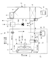
- a heat pump type vehicle air conditioning system 1 includes an HVAC unit (Heating Ventilation and Air Conditioning Unit) 2 and a heat pump type refrigerant circuit 3 capable of cooling and heating.
- the heat pump type vehicle air conditioning system 1 is applied to, for example, an electric powered vehicle (PHEV vehicle) equipped with an engine.
- PHEV vehicle electric powered vehicle
- the HVAC unit 2 switches and introduces either the inside air or the outside air from the vehicle compartment, and the blower 4 that feeds the pressure downstream, and the in-vehicle evaporator 6 disposed on the upstream side in the air flow path 5 connected to the blower 4
- the heater core 8 is disposed downstream of the heater core 8 and is capable of circulating a heat medium (brine) such as hot water through the heat medium circulation circuit 7, an amount of air flowing through the heater core 8, and an amount of air bypassed.
- the air mix damper 9 is provided to adjust the ratio and adjust the temperature of the temperature-controlled air blown into the vehicle compartment.
- the HVAC unit 2 is installed, for example, in an instrument panel on the vehicle compartment side, and selectively blows temperature-controlled air into the vehicle compartment from a plurality of outlets opened toward the vehicle compartment. It is.
- the exhaust heat from the engine of the PHEV vehicle in addition to the refrigerant / heat medium heat exchanger 16 on the heat pump refrigerant circuit 3 side described later.
- Exhaust heat recovery equipment such as exhaust heat from vehicle drive equipment such as a motor or an inverter, and heat source equipment such as a PTC heater are further provided, and various heat can be effectively used as a heating heat source.
- a heat pump type refrigerant circuit 3 switchable between a cooling cycle and a heating cycle includes an electric compressor 10 for compressing a refrigerant, an external heat exchanger (functions as a condenser during cooling and an evaporator during heating) 11, and a receiver.
- a closed cycle cooling refrigerant circuit (12), a first pressure reducing means 13 with an on-off valve function, and an in-vehicle evaporator 6 provided in the HVAC unit 2 are sequentially connected via a refrigerant pipe 14 in this order
- a cooling cycle) 15 is provided.
- the cooling refrigerant circuit 15 can be substantially equivalent to the refrigerant circuit used in the current vehicle air conditioning system applied to an engine drive type vehicle.
- the high temperature / high pressure refrigerant gas discharged from the motor compressor 10 and the heat medium circulating the heat medium circulation circuit 7 to the heater core 8 in the discharge pipe 14 A from the motor compressor 10 The refrigerant / heat medium heat exchanger 16 which exchanges heat is provided, and the three-way switching valve 17 is provided downstream thereof.
- the heating bypass circuit 18 is connected to the three-way switching valve 17, and the other end is connected to the receiver 12 so that the refrigerant condensed by the refrigerant / heat medium heat exchanger 16 is stored in the receiver 12 during heating. It is configured to be able to be introduced.
- a second pressure reducing means 19 with an open / close valve function is provided between the outlet refrigerant pipe 14C of the receiver 12 and the refrigerant outlet side (one end side of the heat exchanger 11 outside) of the heat exchanger 11 during cooling operation.
- a second circuit 20 for heating is connected, and a refrigerant inlet side (the other end side of the external heat exchanger 11) during cooling operation of the external heat exchanger 11 and a suction pipe 14F to the electric compressor 10 ,
- a third circuit 22 for heating provided with a solenoid valve 21 is connected.
- the third circuit 22 including the heat exchanger 11 and the solenoid valve 21 includes a discharge pipe 14A, a refrigerant pipe 14B (heating bypass circuit 18), an outlet refrigerant pipe 14C, a refrigerant pipe 14D (second circuit 20), and a refrigerant pipe in this order.
- a closed cycle heating refrigerant circuit (heating cycle) 23 connected via a suction pipe 14F (third circuit 22) and a suction pipe 14F can be configured.
- a fan 24 for circulating external air is attached to the heat exchanger 11 outside the vehicle.
- check valves 25 and 26 are integrally incorporated in the two refrigerant inlets to which the heating bypass circuit 18 from the three-way switching valve 17 and the refrigerant piping 14 from the external heat exchanger 11 are connected. It is considered as a receiver 12 with a fixed check valve. And, as the first pressure reducing means 13 and the second pressure reducing means 19 with the on-off valve function, it is possible to use a temperature type automatic expansion valve with a solenoid valve.
- the temperature type automatic expansion valve with a solenoid valve is provided on the refrigerant inlet side of the in-vehicle evaporator 6 or on the refrigerant inlet side of the external heat exchanger 11 functioning as the evaporator. It is integrated with the expansion valve.
- the electromagnetic valve is configured such that the movable iron core advances and retracts in the axial direction by energization of the electromagnetic coil, and the valve body opens and closes the inlet-side flow path.
- the temperature type automatic expansion valve senses the temperature and pressure of the refrigerant in the outlet side refrigerant passage 55 through which the refrigerant evaporated in the in-vehicle evaporator 6 or the external heat exchanger 11 flows, and the opening degree of the valve is adjusted.
- the solenoid valve and the temperature type automatic expansion valve may be configured by connecting independent and independent standard solenoid valves and temperature type automatic expansion valves in series.
- the above-mentioned temperature type automatic expansion valve with a solenoid valve opens the solenoid valve during operation using one or both of the in-vehicle evaporator 6 or the outside heat exchanger 11 functioning as an evaporator, and via the inlet side flow path
- the refrigerant adiabatically expanded by the temperature type automatic expansion valve is supplied to the in-vehicle evaporator 6 or the out-of-vehicle heat exchanger 11.
- the refrigerant flow rate can be automatically controlled by the temperature type automatic expansion valve so that the degree of refrigerant superheat at the outlet of each evaporator becomes constant.
- an electronic expansion valve may be used instead of the temperature type automatic expansion valve with a solenoid valve as the first pressure reducing means 13 and the second pressure reducing means 19 with an on-off valve function. It does not exclude use.
- the refrigerant compressed by the electric compressor 10 in the cooling mode, is the refrigerant / heat medium heat exchanger 16, the three-way switching valve 17, the condenser as shown by solid arrows.
- the cooling refrigerant circuit (cooling cycle) 15 that circulates through the external heat exchanger 11, the receiver 12, the first pressure reducing means 13 with the on-off valve function, and the in-vehicle evaporator 6 in this order and returning to the electric compressor 10 again. Circulate.
- the refrigerant compressed by the electric compressor 10 is the refrigerant / heat medium heat exchanger 16, the three-way switching valve 17, the heating bypass circuit 18, the receiver 12, the on-off valve as shown by the broken arrow.
- a second circuit 20 provided with a second pressure reducing means 19 with a function, an external heat exchanger 11 functioning as an evaporator, and a third circuit 22 provided with a solenoid valve 21 circulate in this order and return to the electric compressor 10 again.
- the heating refrigerant circuit (heating cycle) 23 circulates. Then, in the refrigerant / heat medium heat exchanger 16, a heat medium (brine) such as warm water circulating in the heat medium circulation circuit 7 is heated and supplied to the heater core 8.
- the high-temperature, high-pressure refrigerant gas compressed by the electric compressor 10 passes through the refrigerant / heat medium heat exchanger 16 and the three-way switching valve 17 by the discharge pipe 14A to function as a condenser.
- heat is exchanged with outside air ventilated by the fan 24 to condense and liquefy.
- the liquid refrigerant is introduced into the receiver 12 through the check valve 26 and temporarily stored since the solenoid valve of the temperature type automatic expansion valve with the solenoid valve constituting the second pressure reducing means 19 is closed. It is led to the first pressure reducing means 13 through the outlet refrigerant pipe 14C, and is decompressed to be in a gas-liquid two-phase state, and is supplied to the in-vehicle evaporator 6.
- the refrigerant evaporated by heat exchange with the inside air or the outside air blown from the blower 4 by the in-vehicle evaporator 6 is sucked into the electric compressor 10 through the suction pipe 14F and recompressed. The same cycle is repeated thereafter.
- the cooling refrigerant circuit 15 is not different from the cooling cycle of the current system used in an engine drive type vehicle, and can be shared as it is.
- the inside air or the outside air cooled by exchanging heat with the refrigerant in the process of passing through the in-vehicle evaporator 6 is blown out into the vehicle interior to provide cooling of the vehicle interior.
- the heat exchange in the refrigerant / heat medium heat exchanger 16 is interrupted by closing the heat medium circulation circuit 7 which circulates the heat medium to the refrigerant / heat medium heat exchanger 16 and the heater core 8. Can.
- the refrigerant compressed by the electric compressor 10 is led to the refrigerant / heat medium heat exchanger 16 through the discharge pipe 14A and exchanges heat with the heat medium circulating in the heat medium circulation circuit 7 to condense. It liquefies and heats the heat medium.
- the heat medium is circulated to the heater core 8 and provided for heating.
- the refrigerant condensed in the refrigerant / heat medium heat exchanger 16 is introduced into the receiver 12 through the three-way switching valve 17 and the heating bypass circuit 18 and temporarily stored, and then the solenoid valve constituting the first pressure reducing means 13 is provided.
- the check valve 26 maintains the closed state by the pressure difference, and the refrigerant does not flow from the external heat exchanger 11 side through the refrigerant pipe 14 to the receiver 12, and thus is supplied to the external heat exchanger 11.
- the refrigerant is heat-exchanged with the outside air ventilated by the fan 24 by the external heat exchanger 11 functioning as an evaporator, and is absorbed by the outside air and evaporated, and then the third circuit 22 equipped with the solenoid valve 21 and the suction pipe It is drawn into the electric compressor 10 through 14F and recompressed.
- this heating refrigerant circuit 23 can perform heat pump heating by using outside air as a heat source.
- the refrigerant / heat medium heat exchanger 16, the three-way switching valve 17, the heating bypass circuit 18, and the cooling refrigerant circuit 15 substantially equivalent to the cooling refrigerant circuit of the current system.
- a heat pump type refrigerant circuit 3 is configured by adding a second circuit 20 having a second pressure reducing means 19 and a third circuit 22 having a solenoid valve 21.
- an in-vehicle evaporator 6 on the upstream side and brine such as hot water on the downstream side By using the HVAC unit 2 similar to the HVAC of the current system in which the heater core 8 capable of circulating is arranged, two heats of the in-vehicle evaporator 6 and the external heat exchanger 11 (function as a condenser) in the cooling mode Cooling operation and heating operation by operating the exchanger and functioning two heat exchangers of the refrigerant / heat medium heat exchanger 16 and the external heat exchanger 11 (function as an evaporator) in the heating mode It can be carried out.
- the vehicle air conditioning system 1 can be configured, and simplification of the configuration, downsizing, and cost reduction can be achieved.
- the HVAC equivalent to the current system in which a heater core 8 of a type in which a heat medium including warm water is circulated downstream of the in-vehicle evaporator 6 is disposed as the HVAC unit 2 can be used as it is.
- Heat using a variety of heat sources such as recovering the exhaust heat of the engine, motor, inverter, etc. with a heat medium, or heating the heat medium with a PTC heater or the like to be a heating heat source, etc. Is possible.
- the refrigerant / heat medium heat exchanger 16 is provided in the discharge pipe 14A of the electric compressor 10 and the three-way switching valve 17 is provided downstream thereof, the three-way switching valve 17 can be installed on the CRFM 27 side, The mountability to a vehicle can be improved.
- the receiver 12 in which the heat pump type vehicle air conditioning system 1 is incorporated is the receiver 12 with a check valve in which the check valves 25 and 26 are incorporated in the refrigerant inlet, for cooling not used in the operation mode
- the refrigerant circuits 15 and 23 for heating can be shut off by the check valves 25 and 26 incorporated in the refrigerant inlets of the receiver 12, and the backflow of the refrigerant to the refrigerant circuits 15 and 23 can be prevented.
- the number of connecting parts such as flanges is reduced as compared with the case where receiver 12 and check valves 25 and 26 are separately provided in heat pump type refrigerant circuit 3
- the heat pump type refrigerant circuit 3 can be simplified and the cost can be reduced.
- the first pressure reducing means 13 and the second pressure reducing means 19 can be switched and used by using the on-off valve function, and at the time of heating mode, the outside heat exchanger 11 and the inside evaporator 6 can be used. It is possible to carry out combined driving.
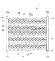
- the external heat exchanger 11 is a so-called multi-flow heat exchanger, and the tube 33 and the fins 34 are disposed between the two headers 31 and 32.
- the inflowing refrigerant branches into a plurality of tubes 33 and flows, and thereafter, the refrigerant flowing into each of the tubes 33 flows and joins in the other second header 32.
- the heat exchanger outside the vehicle 11 forms two sides where two headers 31 and 32 face each other, and has a substantially plate shape. Air is supplied from one surface side of the heat exchanger outside the vehicle 11, and the air is discharged from the other surface side on the back side of the one surface. When air passes through the heat exchanger 11, heat exchange is performed with the refrigerant flowing inside the tube 33.
- the external heat exchanger 11 is applied to, for example, the refrigerant circuit of the heat pump system as described above, and functions as a condenser during cooling operation and as an evaporator during heating operation. That is, when the external heat exchanger 11 functions as a condenser, the heat of the refrigerant flowing into the external heat exchanger 11 is released to the outside, and the refrigerant is cooled. At this time, the gaseous refrigerant flows into the external heat exchanger 11, and the refrigerant is liquefied in the external heat exchanger 11.
- the refrigerant flowing into the external heat exchanger 11 absorbs external heat, and the refrigerant is heated. At this time, a two-phase refrigerant of liquid and gas having passed through the second pressure reducing means 19 flows into the external heat exchanger 11, and the refrigerant is vaporized in the external heat exchanger 11.
- the heat exchanger outside the vehicle 11 is disposed adjacent to between the two tubes 33 and the two tubes 31 and 32 extending in the vertical direction, the tube 33 disposed between the two headers 31 and 32, and And the like.
- the tube 33 and the fins 34 for example, an alloy such as an aluminum alloy or a metal such as aluminum is used.
- Each of the headers 31 and 32 has a hollow cylindrical shape, and a plurality of tubes 33 are fixed at substantially equal intervals in the vertical direction.
- the insides of the headers 31 and 32 and the inside of the tube 33 communicate with each other, and the refrigerant flows through the insides of both.
- the two headers 31 and 32 are a first header 31 and a second header 32, respectively.
- the refrigerant is transferred from the first header 31 to the second header 32, and then from the second header 32 to the first header 31.
- the first header 31 is an inlet side into which the refrigerant flows when the external heat exchanger 11 functions as a condenser, and is an outlet side from which the refrigerant flows out when it functions as an evaporator.
- the second header 32 is an outlet side from which the refrigerant flows out when the external heat exchanger 11 functions as a condenser, and is an inlet side into which the refrigerant flows when functioning as an evaporator.
- the tube 33 has a flat shape, and a plurality of flow passages extending in the longitudinal direction of the tube 33 are formed therein.
- the plurality of flow passages are arranged in parallel in the width direction of the tube 33.
- One end of the tube 33 is connected to the first header 31, and the other end of the tube 33 is connected to the second header 32.
- a plurality of thin plates are arranged in the fins 34, and a gap is provided between the plurality of thin plates so that air can flow from one surface of the external heat exchanger 11 to the other surface.
- the fins 34 are in contact with the tube 33 at upper and lower portions, and the heat of the refrigerant flowing through the tube 33 is transferred.
- the refrigerant flowing from the opening of the first header 31 flows downward from above the first header 31. It flows into the flow passage of each tube 33 connected to the 1 header 31.
- the refrigerant flowing into the flow passage of the tube 33 flows toward the second header 32 and flows into the second header 32.
- the refrigerant flowing into the second header 32 flows downward from above and flows out of the opening of the second header 32.
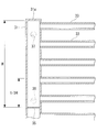
- the partition plate 35 may be provided inside the headers 31 and 32, or the partition plate may not be provided. If no divider plate is provided, the headers 31, 32 communicate with all the tubes 33 connected to the headers 31, 32. Therefore, it is difficult for the refrigerant flowing into the headers 31 and 32 to efficiently circulate the refrigerant, but the refrigerant can flow to all the tubes 33.
- each of the headers 31 and 32 When one partition plate is provided in each of the first header 31 and the second header 32, the inside of each of the headers 31 and 32 is between the uppermost surfaces 31 a and 32 a of the headers 31 and 32 and the partition plate 35 and the partition plate 35 And the lowermost surfaces 31b and 32b of the headers 31 and 32, respectively.
- the divided space inside the headers 31 and 32 communicates with the tube 33 connected in the divided space. Therefore, the refrigerant which has flowed into each divided space of the headers 31 and 32 flows only to the tube 33 connected to the divided space. Thereby, the refrigerant is transferred from the first header 31 to the second header 32, then from the second header 32 to the first header 31, and further from the first header 31 to the second header 32 in the external heat exchanger 11. Can be flowed back.
- partition plates 35 may be provided in one header 31 and 32, and division space may be formed between the partition plates 35 which the partition plate 35 adjoins. In this case, the refrigerant reciprocates in the outside heat exchanger 11 two or more times. Further, the partition plate 35 may be provided only on the first header 31, and the partition plate 35 may not be provided on the second header 32. In this case, the refrigerant reciprocates only within the heat exchanger 11 outside the vehicle.
- the openings 36, 37, 38 provided in the first header 31 and the second header 32 that is, the refrigerant inlet and the refrigerant outlet will be described.
- the first opening 36 is formed at a lower position of the total height of the divided space divided by the uppermost surface 31 a of the first header 31 and the partition plate 35.
- the first opening 36 is desirably provided in the vicinity of the partition plate 35, and provided between the partition plate 35 and a position about one third of the height of the divided space from the partition plate 35. It may be done.
- the first opening portion 36 serves as a refrigerant outlet portion through which the refrigerant flows when the external heat exchanger 11 functions as an evaporator.
- the second opening 37 is formed at a position higher than the first opening 36 and in a divided space divided by the uppermost surface of the first header 31 and the partition plate 35.
- the second opening 37 serves as a refrigerant inlet portion into which the refrigerant flows when the external heat exchanger 11 functions as a condenser.
- first opening 36 and the second opening 37 are separately provided in the first header 31, when connecting the piping to the heat exchanger outside the vehicle 11, when the opening is made common and the piping is branched In comparison, piping work becomes easier.
- a third opening 38 is formed in the second header 32 near the lowermost surface of the second header 32.
- the third opening 38 is a refrigerant outlet where the refrigerant flows out when the external heat exchanger 11 functions as a condenser, and is a refrigerant inlet where the refrigerant flows when it functions as an evaporator.
- the refrigerant flows from the third opening 38, and the refrigerant flows from the lower portion to the upper portion of the external heat exchanger 11.
- the liquefied refrigerant is always present in the lower part of the heat exchanger outside the vehicle 11 and suppresses an increase in pressure loss inside the heat exchanger outside the vehicle 11 compared to the case where the refrigerant flows from the upper part to the lower part it can.
- the first opening 36 serving as a refrigerant outlet from which the refrigerant flows out is formed at a low position of the divided space of the first header 31, when the external heat exchanger 11 functions as an evaporator, When all the refrigerant reaching the outlet of the exchanger 11 can not be gasified, the liquid refrigerant can be discharged to the outside through the first opening 36 at the height of the first opening 36. The amount of liquid refrigerant accumulated in the first header 31 can be suppressed.
- the heat exchanger 11 functions as an evaporator
- the refrigerant is liquefied in the vicinity of the second opening 37 higher than the first opening 36 and the piping connected to the second opening 37
- the refrigerant can flow out from the first opening 36 formed at the lower position of the divided space of the first header 31.
- the first opening 36 serving as the refrigerant outlet from which the refrigerant flows out when functioning as the evaporator functions as the condenser. It is formed separately from the second opening 37 where the refrigerant flows.
- the first opening 36 is formed at a lower position than the second opening 37 and at a lower position of the divided space of the first header 31.
- the refrigerant outlet when functioning as an evaporator and the mounting position of the refrigerant inlet when functioning as a condenser are It was the top.
- the surplus refrigerant is accumulated to a position where the top of the header of the heat exchanger outside the vehicle 11 is reached.
- the amount of surplus refrigerant increases.
- the amount of surplus liquid refrigerant accumulated in the first header 31 can be suppressed.
- the mounting positions of the refrigerant outlet when functioning as an evaporator and the refrigerant inlet when functioning as a condenser are It was the same height or only one opening was used to share both.
- the refrigerant liquefied by the refrigerant inlet used when functioning as a condenser, and the pipe connected to the refrigerant inlet for the condenser has the same height as that of the refrigerant outlet. It is not discharged until it reaches the end, or it is not discharged from the outside heat exchanger 11 at all.
- the first opening 36 is formed at a lower position than the second opening 37 and at a lower position of the divided space of the first header 31, the vicinity of the second opening 37 or Even if the refrigerant is liquefied by the pipe connected to the second opening 37, the refrigerant can flow out from the first opening 36.
Abstract
La présente invention a pour but de pourvoir à un échangeur de chaleur et à un système de pompe à chaleur pouvant réduire la quantité d'un fluide de refroidissement s'accumulant dans un échangeur de chaleur extérieur pendant une opération de chauffage, et pouvant diminuer la quantité appropriée du fluide de refroidissement pendant l'opération de chauffage. Un échangeur de chaleur (11) à l'extérieur d'un véhicule est muni d'une première colonne creuse (31), une seconde colonne creuse (32) disposée en regard de la première colonne (31) et une pluralité de tubes (33) disposés entre la première colonne (31) et la seconde colonne (32), les tubes (33) étant reliés à la première colonne (31) et à la seconde colonne (32). Un panneau diviseur (35) destiné à diviser l'intérieur de la première colonne (31) est disposé dans la première colonne (31) ; une première ouverture (36) est formée du côté du panneau diviseur (35) dans la première colonne (31) entre la section supérieure de la première colonne (31) et le panneau diviseur (35) ; pendant le fonctionnement en tant que générateur de vapeur, un fluide de refroidissement est alimenté à partir de la partie inférieure de la première colonne (31) ou de la seconde colonne (32), et la première ouverture (36) devient un orifice de sortie pour le fluide de refroidissement.
Priority Applications (3)
| Application Number | Priority Date | Filing Date | Title |
|---|---|---|---|
| DE112016003745.7T DE112016003745T5 (de) | 2015-08-19 | 2016-06-23 | Wärmetauscher und wärmepumpensystem |
| US15/739,501 US10449833B2 (en) | 2015-08-19 | 2016-06-23 | Heat exchanger and heat pump system |
| CN201680037581.3A CN107709898B (zh) | 2015-08-19 | 2016-06-23 | 热交换器以及热泵系统 |
Applications Claiming Priority (2)
| Application Number | Priority Date | Filing Date | Title |
|---|---|---|---|
| JP2015-161905 | 2015-08-19 | ||
| JP2015161905A JP6537928B2 (ja) | 2015-08-19 | 2015-08-19 | 熱交換器及びヒートポンプシステム |
Publications (1)
| Publication Number | Publication Date |
|---|---|
| WO2017029882A1 true WO2017029882A1 (fr) | 2017-02-23 |
Family
ID=58050989
Family Applications (1)
| Application Number | Title | Priority Date | Filing Date |
|---|---|---|---|
| PCT/JP2016/068695 WO2017029882A1 (fr) | 2015-08-19 | 2016-06-23 | Échangeur de chaleur et système de pompe à chaleur |
Country Status (5)
| Country | Link |
|---|---|
| US (1) | US10449833B2 (fr) |
| JP (1) | JP6537928B2 (fr) |
| CN (1) | CN107709898B (fr) |
| DE (1) | DE112016003745T5 (fr) |
| WO (1) | WO2017029882A1 (fr) |
Families Citing this family (2)
| Publication number | Priority date | Publication date | Assignee | Title |
|---|---|---|---|---|
| CN110254169A (zh) * | 2019-06-26 | 2019-09-20 | 曼德电子电器有限公司 | 用于车辆的空调系统和具有其的车辆 |
| CN111472847B (zh) * | 2020-05-11 | 2024-04-12 | 中国电力工程顾问集团西南电力设计院有限公司 | 一种防止轴封汽源管路积水的系统 |
Citations (4)
| Publication number | Priority date | Publication date | Assignee | Title |
|---|---|---|---|---|
| JPH09145186A (ja) * | 1995-11-20 | 1997-06-06 | Fujitsu General Ltd | 空気調和機 |
| JPH10238895A (ja) * | 1997-02-26 | 1998-09-08 | Sanyo Electric Co Ltd | 空気調和装置 |
| JP2001116381A (ja) * | 1999-10-20 | 2001-04-27 | Fujitsu General Ltd | 空気調和機 |
| JP2011102650A (ja) * | 2009-11-10 | 2011-05-26 | Sharp Corp | 熱交換器及びそれを搭載した空気調和機 |
Family Cites Families (10)
| Publication number | Priority date | Publication date | Assignee | Title |
|---|---|---|---|---|
| JP2000304378A (ja) * | 1999-04-23 | 2000-11-02 | Mitsubishi Heavy Ind Ltd | コンデンサ、冷媒系及び車両用空気調和装置 |
| JP2002019444A (ja) * | 2000-07-10 | 2002-01-23 | Denso Corp | ヒートポンプ式空調装置 |
| JP5618368B2 (ja) * | 2010-12-01 | 2014-11-05 | シャープ株式会社 | 熱交換器及びそれを搭載した一体型空気調和機 |
| JP5944154B2 (ja) * | 2011-12-09 | 2016-07-05 | サンデンホールディングス株式会社 | 車両用空気調和装置 |
| JP2013178007A (ja) * | 2012-02-28 | 2013-09-09 | Sharp Corp | パラレルフロー型熱交換器及びそれを備えた機器 |
| JP6216113B2 (ja) | 2012-04-02 | 2017-10-18 | サンデンホールディングス株式会社 | 熱交換器及びそれを用いたヒートポンプシステム |
| JP6037773B2 (ja) | 2012-10-29 | 2016-12-07 | 三菱重工業株式会社 | ヒートポンプ式車両用空調装置及び車両 |
| JP2015098949A (ja) * | 2013-11-18 | 2015-05-28 | トヨタ自動車株式会社 | 熱交換システム |
| JP6405130B2 (ja) | 2014-06-25 | 2018-10-17 | 株式会社Kelk | 熱電発電装置 |
| JP6415943B2 (ja) | 2014-11-21 | 2018-10-31 | 三菱重工サーマルシステムズ株式会社 | ヒートポンプ式車両用空調システム |
-
2015
- 2015-08-19 JP JP2015161905A patent/JP6537928B2/ja active Active
-
2016
- 2016-06-23 DE DE112016003745.7T patent/DE112016003745T5/de not_active Withdrawn
- 2016-06-23 WO PCT/JP2016/068695 patent/WO2017029882A1/fr active Application Filing
- 2016-06-23 CN CN201680037581.3A patent/CN107709898B/zh not_active Expired - Fee Related
- 2016-06-23 US US15/739,501 patent/US10449833B2/en not_active Expired - Fee Related
Patent Citations (4)
| Publication number | Priority date | Publication date | Assignee | Title |
|---|---|---|---|---|
| JPH09145186A (ja) * | 1995-11-20 | 1997-06-06 | Fujitsu General Ltd | 空気調和機 |
| JPH10238895A (ja) * | 1997-02-26 | 1998-09-08 | Sanyo Electric Co Ltd | 空気調和装置 |
| JP2001116381A (ja) * | 1999-10-20 | 2001-04-27 | Fujitsu General Ltd | 空気調和機 |
| JP2011102650A (ja) * | 2009-11-10 | 2011-05-26 | Sharp Corp | 熱交換器及びそれを搭載した空気調和機 |
Also Published As
| Publication number | Publication date |
|---|---|
| CN107709898A (zh) | 2018-02-16 |
| JP2017040421A (ja) | 2017-02-23 |
| US10449833B2 (en) | 2019-10-22 |
| JP6537928B2 (ja) | 2019-07-03 |
| DE112016003745T5 (de) | 2018-04-26 |
| US20180178632A1 (en) | 2018-06-28 |
| CN107709898B (zh) | 2020-04-07 |
Similar Documents
| Publication | Publication Date | Title |
|---|---|---|
| US10744850B2 (en) | Heat pump system for vehicle | |
| JP6218953B2 (ja) | 車両用のヒートポンプシステム | |
| CN109501552B (zh) | 用于车辆的热泵系统 | |
| EP3534090A1 (fr) | Appareil à cycle de pompe à chaleur | |
| US11338646B2 (en) | Device for distributing the coolant in an air-conditioning system of a motor vehicle | |
| JP6415943B2 (ja) | ヒートポンプ式車両用空調システム | |
| WO2020137232A1 (fr) | Régulateur de température | |
| JPWO2015011919A1 (ja) | 車両用空調装置 | |
| JP2017144951A (ja) | 車両用空調装置 | |
| JP2010001013A (ja) | 自動車用加熱、換気、および/または空調装置 | |
| JP6590321B2 (ja) | 車両用空調装置 | |
| JP6760226B2 (ja) | 複合型熱交換器 | |
| KR101894440B1 (ko) | 차량용 히트펌프 시스템의 실외 열교환기 | |
| KR102250000B1 (ko) | 차량용 히트 펌프 시스템 | |
| JP6537928B2 (ja) | 熱交換器及びヒートポンプシステム | |
| JP2020139686A (ja) | 冷凍サイクル装置 | |
| JP6891711B2 (ja) | 複合型熱交換器 | |
| EP1728662A1 (fr) | Système de refroidissement pour climatisation | |
| JP2017172948A (ja) | 熱交換ユニットおよび車両用空調装置 | |
| JP2021124235A (ja) | 冷凍サイクル装置 | |
| JP6191493B2 (ja) | 熱交換システム | |
| KR102182346B1 (ko) | 차량용 히트 펌프 시스템 | |
| JP6606052B2 (ja) | 空調装置 | |
| WO2020129496A1 (fr) | Condensateur et dispositif de climatisation pour véhicule | |
| JP2020190378A (ja) | 熱交換器およびこれを用いたヒートポンプ式冷凍サイクル |
Legal Events
| Date | Code | Title | Description |
|---|---|---|---|
| 121 | Ep: the epo has been informed by wipo that ep was designated in this application |
Ref document number: 16836874 Country of ref document: EP Kind code of ref document: A1 |
|
| WWE | Wipo information: entry into national phase |
Ref document number: 15739501 Country of ref document: US |
|
| WWE | Wipo information: entry into national phase |
Ref document number: 112016003745 Country of ref document: DE |
|
| 122 | Ep: pct application non-entry in european phase |
Ref document number: 16836874 Country of ref document: EP Kind code of ref document: A1 |