WO2017026312A1 - 電池パック - Google Patents
電池パック Download PDFInfo
- Publication number
- WO2017026312A1 WO2017026312A1 PCT/JP2016/072495 JP2016072495W WO2017026312A1 WO 2017026312 A1 WO2017026312 A1 WO 2017026312A1 JP 2016072495 W JP2016072495 W JP 2016072495W WO 2017026312 A1 WO2017026312 A1 WO 2017026312A1
- Authority
- WO
- WIPO (PCT)
- Prior art keywords
- passage
- battery
- fluid
- fin
- side space
- Prior art date
- Legal status (The legal status is an assumption and is not a legal conclusion. Google has not performed a legal analysis and makes no representation as to the accuracy of the status listed.)
- Ceased
Links
Images


Classifications
-
- H—ELECTRICITY
- H01—ELECTRIC ELEMENTS
- H01M—PROCESSES OR MEANS, e.g. BATTERIES, FOR THE DIRECT CONVERSION OF CHEMICAL ENERGY INTO ELECTRICAL ENERGY
- H01M10/00—Secondary cells; Manufacture thereof
- H01M10/60—Heating or cooling; Temperature control
- H01M10/65—Means for temperature control structurally associated with the cells
- H01M10/656—Means for temperature control structurally associated with the cells characterised by the type of heat-exchange fluid
- H01M10/6561—Gases
- H01M10/6566—Means within the gas flow to guide the flow around one or more cells, e.g. manifolds, baffles or other barriers
-
- H—ELECTRICITY
- H01—ELECTRIC ELEMENTS
- H01M—PROCESSES OR MEANS, e.g. BATTERIES, FOR THE DIRECT CONVERSION OF CHEMICAL ENERGY INTO ELECTRICAL ENERGY
- H01M10/00—Secondary cells; Manufacture thereof
- H01M10/60—Heating or cooling; Temperature control
- H01M10/61—Types of temperature control
- H01M10/613—Cooling or keeping cold
-
- H—ELECTRICITY
- H01—ELECTRIC ELEMENTS
- H01M—PROCESSES OR MEANS, e.g. BATTERIES, FOR THE DIRECT CONVERSION OF CHEMICAL ENERGY INTO ELECTRICAL ENERGY
- H01M10/00—Secondary cells; Manufacture thereof
- H01M10/60—Heating or cooling; Temperature control
- H01M10/61—Types of temperature control
- H01M10/617—Types of temperature control for achieving uniformity or desired distribution of temperature
-
- H—ELECTRICITY
- H01—ELECTRIC ELEMENTS
- H01M—PROCESSES OR MEANS, e.g. BATTERIES, FOR THE DIRECT CONVERSION OF CHEMICAL ENERGY INTO ELECTRICAL ENERGY
- H01M10/00—Secondary cells; Manufacture thereof
- H01M10/60—Heating or cooling; Temperature control
- H01M10/62—Heating or cooling; Temperature control specially adapted for specific applications
- H01M10/625—Vehicles
-
- H—ELECTRICITY
- H01—ELECTRIC ELEMENTS
- H01M—PROCESSES OR MEANS, e.g. BATTERIES, FOR THE DIRECT CONVERSION OF CHEMICAL ENERGY INTO ELECTRICAL ENERGY
- H01M10/00—Secondary cells; Manufacture thereof
- H01M10/60—Heating or cooling; Temperature control
- H01M10/65—Means for temperature control structurally associated with the cells
- H01M10/655—Solid structures for heat exchange or heat conduction
- H01M10/6551—Surfaces specially adapted for heat dissipation or radiation, e.g. fins or coatings
-
- H—ELECTRICITY
- H01—ELECTRIC ELEMENTS
- H01M—PROCESSES OR MEANS, e.g. BATTERIES, FOR THE DIRECT CONVERSION OF CHEMICAL ENERGY INTO ELECTRICAL ENERGY
- H01M10/00—Secondary cells; Manufacture thereof
- H01M10/60—Heating or cooling; Temperature control
- H01M10/65—Means for temperature control structurally associated with the cells
- H01M10/655—Solid structures for heat exchange or heat conduction
- H01M10/6556—Solid parts with flow channel passages or pipes for heat exchange
- H01M10/6557—Solid parts with flow channel passages or pipes for heat exchange arranged between the cells
-
- H—ELECTRICITY
- H01—ELECTRIC ELEMENTS
- H01M—PROCESSES OR MEANS, e.g. BATTERIES, FOR THE DIRECT CONVERSION OF CHEMICAL ENERGY INTO ELECTRICAL ENERGY
- H01M10/00—Secondary cells; Manufacture thereof
- H01M10/60—Heating or cooling; Temperature control
- H01M10/65—Means for temperature control structurally associated with the cells
- H01M10/656—Means for temperature control structurally associated with the cells characterised by the type of heat-exchange fluid
- H01M10/6561—Gases
- H01M10/6563—Gases with forced flow, e.g. by blowers
- H01M10/6565—Gases with forced flow, e.g. by blowers with recirculation or U-turn in the flow path, i.e. back and forth
-
- H—ELECTRICITY
- H01—ELECTRIC ELEMENTS
- H01M—PROCESSES OR MEANS, e.g. BATTERIES, FOR THE DIRECT CONVERSION OF CHEMICAL ENERGY INTO ELECTRICAL ENERGY
- H01M50/00—Constructional details or processes of manufacture of the non-active parts of electrochemical cells other than fuel cells, e.g. hybrid cells
- H01M50/20—Mountings; Secondary casings or frames; Racks, modules or packs; Suspension devices; Shock absorbers; Transport or carrying devices; Holders
- H01M50/204—Racks, modules or packs for multiple batteries or multiple cells
-
- H—ELECTRICITY
- H01—ELECTRIC ELEMENTS
- H01M—PROCESSES OR MEANS, e.g. BATTERIES, FOR THE DIRECT CONVERSION OF CHEMICAL ENERGY INTO ELECTRICAL ENERGY
- H01M2220/00—Batteries for particular applications
- H01M2220/20—Batteries in motive systems, e.g. vehicle, ship, plane
-
- Y—GENERAL TAGGING OF NEW TECHNOLOGICAL DEVELOPMENTS; GENERAL TAGGING OF CROSS-SECTIONAL TECHNOLOGIES SPANNING OVER SEVERAL SECTIONS OF THE IPC; TECHNICAL SUBJECTS COVERED BY FORMER USPC CROSS-REFERENCE ART COLLECTIONS [XRACs] AND DIGESTS
- Y02—TECHNOLOGIES OR APPLICATIONS FOR MITIGATION OR ADAPTATION AGAINST CLIMATE CHANGE
- Y02E—REDUCTION OF GREENHOUSE GAS [GHG] EMISSIONS, RELATED TO ENERGY GENERATION, TRANSMISSION OR DISTRIBUTION
- Y02E60/00—Enabling technologies; Technologies with a potential or indirect contribution to GHG emissions mitigation
- Y02E60/10—Energy storage using batteries
Definitions
- the present invention relates to a battery pack having a plurality of battery cells housed inside a case.
- a battery pack having battery cells for example, a battery pack described in Patent Document 1 is known.
- a battery pack (battery cooling device) described in Patent Literature 1 a plurality of battery cells, a housing that houses the plurality of battery cells, and a fluid that exchanges heat (cools) with the plurality of battery cells in the housing flow.
- a circulation passage and a blower for circulating fluid in the circulation passage are provided.
- the casing has a hexahedral shape having a top wall, a bottom wall, and four side walls.
- the circulation passage includes a side wall side passage along the side wall, a top wall side passage along the top wall, a battery passage formed by a gap between adjacent battery cells, and a bottom wall side passage along the bottom wall. The fluid blown out from the blower flows in the order of the side wall side passage, the top wall side passage, the battery passage, and the bottom wall side passage.
- the present invention has been made in view of the above problems, and an object of the present invention is to provide a battery pack in which variation in temperature distribution of battery cells is reduced.
- a first invention to be disclosed includes a plurality of battery cells, a housing that houses the plurality of battery cells, and a heat exchange unit that is formed in the housing and moves heat of the battery cells to the housing.
- a battery pack comprising a circulation passage through which a fluid circulates and a blower that circulates the fluid through the circulation passage.
- the circulation passage includes a plurality of battery passages formed by gaps between adjacent battery cells, a space facing the inflow port of the battery passage, and an inflow side space for distributing fluid to each inflow port, and the battery passage A space that faces the outflow port of the gas outlet, and the outflow side space that collects fluid from each outflow port, and the inflow side space and the outflow side space are different passages that are along the inner surface of the housing.
- a passage along the body The circulation passage is formed such that at least one of the flow velocity of the fluid in the inflow side space and the flow velocity of the fluid in the outflow side space is slower than the flow velocity of the fluid in the passage along the housing.
- the sum of the flow velocity energy and pressure energy of the fluid flowing through the circulation passage is constant according to Bernoulli's theorem.
- the pressure energy is reduced by the increase of the flow velocity energy.
- the passage cross-sectional area is increased to reduce the flow velocity, this means that the pressure energy increases by the amount of decrease in the flow velocity energy.
- increasing the pressure energy means that the fluid is statically pressurized and the flow distribution is made uniform. In other words, there is little variation in the pressure distribution of the fluid in the static pressure space.
- At least one of the fluid flow velocity (V2) in the inflow side space and the fluid flow velocity (V4) in the outflow space is equal to the fluid flow velocity ( Slower than V1). Therefore, by making the flow velocity in the inflow side space slower than the flow velocity in the passage along the housing (V2 ⁇ V1), the fluid in the inflow side space is made static pressure and the pressure distribution is made uniform. Therefore, the distribution variation of the inflow amount of the fluid flowing into the battery passage from the inflow side space is reduced. Further, by making the flow velocity in the outflow side space slower than the flow velocity in the passage along the casing (V4 ⁇ V1), the fluid in the outflow side space is statically pressurized and the pressure distribution is made uniform. Therefore, the distribution variation of the outflow amount of the fluid flowing out from the battery passage to the outflow side space is reduced.
- variation in distribution is reduced with respect to at least one of the inflow amount to the battery passage and the outflow amount from the battery passage. Therefore, variation in the flow distribution of the fluid flowing through the battery passage can be reduced, and consequently variation in the amount of heat released from the battery cells can be reduced. Therefore, the temperature distribution variation of a battery cell can be reduced, As a result, it can accelerate
- the flow velocity in the passage along the housing is faster than the flow velocity in at least one of the inflow side space and the outflow side space. Therefore, the fluid in the passage along the housing increases the flow velocity energy by the amount of decrease in pressure energy, and the flow velocity increases as compared with the fluid in the inflow side space or the outflow side space. Therefore, the heat transfer rate when the heat of the fluid moves to the housing can be increased, and the amount of heat released from the housing to the external air can be increased. Moreover, the higher the flow rate, the smaller the variation in heat transfer coefficient that accompanies the variation in flow rate. Therefore, the fluid temperature variation that the temperature of the fluid differs depending on the outflow location in the passage along the housing can be suppressed, and consequently, the temperature distribution variation of the battery cell can be reduced.
- a second invention to be disclosed includes a plurality of battery cells, a housing that houses the plurality of battery cells, and a heat exchange unit that is formed in the housing and moves heat of the battery cells to the housing.
- a battery pack comprising a circulation passage through which a fluid circulates and a blower that circulates the fluid through the circulation passage.
- the circulation passage includes a plurality of battery passages formed by gaps between adjacent battery cells, a space facing the inflow port of the battery passage, and an inflow side space for distributing fluid to each inflow port, and the battery passage A space that faces the outflow port of the gas outlet, and the outflow side space that collects fluid from each outflow port, and the inflow side space and the outflow side space are different passages that are along the inner surface of the housing.
- a passage along the body The circulation passage is formed so that at least one of the flow velocity of the fluid in the inflow side space and the flow velocity of the fluid in the outflow side space is slower than the flow velocity of the fluid in the battery passage.
- At least one of the fluid flow velocity (V2) in the inflow side space and the fluid flow velocity (V4) in the outflow space is slower than the fluid flow velocity (V3) in the battery passage. . Therefore, by making the flow rate in the inflow side space slower than the flow rate in the battery passage (V2 ⁇ V3), the fluid in the inflow side space is made static pressure and the pressure distribution is made uniform. Therefore, the distribution variation of the inflow amount of the fluid flowing into the battery passage from the inflow side space is reduced. Further, by making the flow rate in the outflow side space slower than the flow rate in the battery passage (V4 ⁇ V3), the fluid in the outflow side space is made static and the pressure distribution is made uniform. Therefore, the distribution variation of the outflow amount of the fluid flowing out from the battery passage to the outflow side space is reduced.
- the distribution variation is reduced with respect to at least one of the inflow amount to the battery passage and the outflow amount from the battery passage. Therefore, variation in the flow distribution of the fluid flowing through the battery passage can be reduced, and consequently variation in the amount of heat released from the battery cells can be reduced. Therefore, the temperature distribution variation of a battery cell can be reduced, As a result, it can accelerate
- the flow velocity in the battery passage is faster than the flow velocity in at least one of the inflow side space and the outflow side space. Therefore, the fluid in the battery passage increases the flow velocity energy by the amount of decrease in pressure energy, and the flow velocity increases as compared with the fluid in the inflow side space or the outflow side space. Therefore, the heat transfer rate when the heat of the battery cell moves to the fluid can be increased, and the amount of heat released from the battery cell to the fluid can be increased. Moreover, the higher the flow rate, the smaller the variation in heat transfer coefficient that accompanies the variation in flow rate. Therefore, the temperature distribution variation reduction of a battery cell can be promoted.
- the variation in the flow velocity distribution is promoted as the flow velocity energy increases, but as described above, static pressure is generated in the inflow side space or the outflow side space. Therefore, it is possible to achieve both the variation in the temperature distribution of the battery cell due to the variation in the distribution of the fluid to the battery passage and the increase in the heat radiation amount in the battery passage.
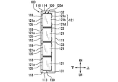
- FIG. 2 is a cross-sectional view taken along line II-II in FIG.
- FIG. 3 is a cross-sectional view taken along line III-III in FIG.
- FIG. 4 is a cross-sectional view taken along line IV-IV in FIG.
- It is a disassembled perspective view which shows an internal fin.
- It is a perspective view which shows an external fin.
- It is a perspective view which shows an external duct.
- a battery pack 100 according to a first embodiment which is an example of the present invention will be described with reference to FIGS.
- the battery pack 100 is a hybrid vehicle using a motor driven by electric power charged in the battery and an internal combustion engine as a travel drive source, or an electric vehicle using a motor as a travel drive source. Used for.
- the plurality of battery cells 121 included in the battery pack 100 are, for example, a nickel hydrogen secondary battery, a lithium ion secondary battery, an organic radical battery, or the like.
- the battery pack 100 is installed in a pack accommodation space (not shown) such as a trunk room of a vehicle or a back area of the trunk room provided below the trunk room.
- This pack storage space can also store spare tires, tools, and the like, for example.
- the battery pack 100 is installed in the pack accommodation space with the bottom wall 112 and the bottom wall side passage 135 positioned downward.
- the battery pack 100 may be installed below a front seat or a rear seat provided in a vehicle cabin.
- the battery pack 100 is installed below the front seat, the rear seat, etc. with the bottom wall 112 and the bottom wall side passage 135 positioned downward.
- the space where the battery pack 100 is installed below the rear seat may be communicated with the trunk room back area below the trunk room.
- the installation space can also be configured to communicate with the outside of the vehicle.
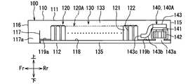
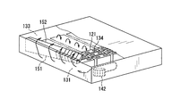
- the battery pack 100 includes a case 110, an assembled battery 120 (cell stack 120A), a circulation passage 130, a blower 140, and the like.
- the case 110 forms a sealed internal space isolated from the outside.
- the assembled battery 120 includes a plurality of battery cells 121 that are connected to be energized.
- the circulation passage 130 is a passage formed in the case 110 and through which a fluid for heat exchange flows.
- the blower 140 circulates the fluid through the circulation passage 130.
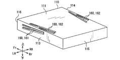
- internal fins 150 (151 and 152) are provided inside the case 110, and external fins 160 (161 and 162) are provided outside the case 110 (FIGS. 5 and 6). reference). Further, an external duct 170 having a blower 172 is provided outside the external fin 160 (see FIG. 7).
- Fr indicates the vehicle front side
- Rr indicates the vehicle rear side
- RH indicates the vehicle right side
- LH indicates the vehicle left side.
- the Fr-Rr direction is referred to as the front-rear direction
- the RH-LH direction is referred to as the left-right direction
- the action direction of gravity is referred to as the vertical direction.
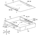
- the case 110 is a housing that houses the assembled battery 120 and the blower 140 (140A, 140B).
- the case 110 has a box shape composed of a plurality of walls surrounding an internal space, and is formed of a molded product of an aluminum plate or an iron plate.
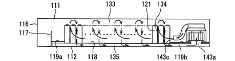
- the case 110 is, for example, a rectangular parallelepiped that is flat in the vertical direction, and has six surfaces, that is, the top wall 111, the bottom wall 112, the first side wall 113, the second side wall 114, the third side wall 115, and the fourth side wall 116. It is a hexahedron shape having.
- the case 110 also has a partition wall 117 that partitions the inside, and a reinforcing beam 118 on the bottom wall 112.
- the top wall 111 is a wall that forms the upper surface of the case 110, and is a rectangular wall having long sides in the front-rear direction.
- the bottom wall 112 is a wall that forms the lower surface of the case 110 and has the same shape as the top wall 111.
- the first and second side walls 113 and 114 are walls that form the left and right sides of the case 110, and are elongated rectangular walls having long sides in the front-rear direction.
- the first and second side walls 113 and 114 are in a positional relationship facing each other.
- the third and fourth side walls 115 and 116 are walls that form the front and rear sides of the case 110, and are elongated rectangular walls having long sides in the left-right direction.
- the third and fourth side walls 115 and 116 are in a positional relationship facing each other.
- the third and fourth side walls 115 and 116 are walls orthogonal to the first and second side walls 113 and 114.
- the case 110 may be manufactured by forming a box-shaped space inside by joining and assembling a plurality of case bodies instead of using the walls 111 to 116 described above. Moreover, you may make it form a some convex part or a recessed part in the surface of a predetermined wall among the several walls of case 110, in order to enlarge a thermal radiation area.
- the direction along the long sides of the first and second side walls 113, 114 corresponds to the front-rear direction
- the direction along the long sides of the third and fourth side walls 115, 116 is left and right. It corresponds to the direction.
- the partition wall 117 is disposed in the vicinity of the fourth side wall 116 inside the case 110, and is a wall that connects the first and second side walls 113, 114 in parallel with the fourth side wall 116.
- the partition wall 117 extends from the upper surface of the bottom wall 112, that is, the inner surface of the case 110 to an intermediate position in the vertical direction of the case 110.
- a space 117 a is formed between the partition wall 117 and the fourth side wall 116.
- a battery management unit (not shown) is accommodated in the space 117a.
- the battery management unit (Battery Management Unit) is configured to be able to communicate with various electronic control devices mounted on the vehicle.
- the battery management unit is a device that manages at least the amount of electricity stored in the battery cell 121, and is an example of a battery control unit that performs control related to the battery cell 121. Further, the battery management unit may be a device that monitors current, voltage, temperature, and the like related to the battery cell 121 and manages an abnormal state of the battery cell 121, electric leakage, and the like.
- a signal related to the current value detected by the current sensor is input to the battery management unit.
- the battery management unit includes an input circuit, a microcomputer, an output circuit, and the like. Battery information is stored as data in the storage means of the microcomputer.
- the stored battery information data includes, for example, the battery voltage, the charging current, the discharging current, and the battery temperature in the battery pack 100.
- the battery management unit also functions as a control device that controls the operations of the fans 140A and 140B, the fan 172, and the PTC heater 144. Temperature information detected by a temperature detector that detects the temperature of the battery cell 121 is input to the battery management unit.
- the temperature detector is provided in each battery cell 121 or a predetermined battery cell 121 in the plurality of battery cells 121.
- the temperature detector can be configured by a temperature detection line, a temperature sensor, or the like that outputs a signal to the battery management unit.
- the battery management unit operates each of the fans 140A and 140B, the fan 172, and the PTC heater 144 when a condition for performing battery cooling or battery heating according to the battery temperature detected by the temperature detector is established. Control.
- the beam 118 is a reinforcing member for improving the strength of the case 110, and is arranged in parallel with the upper surface of the bottom wall 112, that is, the inner surface of the case 110. A plurality are provided. In the present embodiment, five beams 118 are set.
- the beam 118 is formed in an elongated bar shape, and is provided on the bottom wall 112 so that the longitudinal direction thereof faces the front-rear direction with respect to the case 110 and is arranged at equal intervals in the left-right direction.
- the beam 118 is formed separately from the case 110, and is formed of, for example, an aluminum material or an iron material. Out of the five beams 118, the two outer beams 118 are arranged along (contact with) the first and second side walls 113 and 114, respectively. Further, the remaining three beams 118 are arranged between the two beams 118. The intervals between the five beams 118 are equal.
- the pitch (distance between center lines) between the beams 118 is set to be equal to the horizontal dimension of the battery cell 121.
- the dimension between the adjacent beams 118 among the plurality of beams 118 is set to be larger than the width dimension of one beam 118.
- the width dimension of the beam 118 is a dimension in a direction in which the beams 118 are arranged.
- the length of the beam 118 is set to be longer than the length in the direction along the beam 118 in the plurality of battery cells 121 as a whole. That is, the longitudinal dimension of the beam 118 is set to be longer than the dimension in the stacking direction of the cell stack 120 ⁇ / b> A formed by the plurality of battery cells 121.
- a plate-shaped blocking wall 119 a connected from the first side wall 113 to the second side wall 114 is provided on the upper surface of the plurality of beams 118. Yes. The upper side of the space between the beams 118 is blocked by the blocking wall 119a.
- a plate-shaped blocking wall 119b connected from the first side wall 113 to the second side wall 114 is formed on the upper surface of the plurality of beams 118. Is provided. The upper side of the space between the beams 118 is blocked by the blocking wall 119b.
- the assembled battery 120 is formed by providing a plurality of cell stacks 120A in which a plurality of battery cells 121 are stacked.
- one cell stack 120A is formed by 20 battery cells 121, and four cell stacks 120A are arranged to form an assembled battery 120 (FIG. 1).
- the battery cell 121 has a rectangular parallelepiped shape that is flat in the front-rear direction, and includes a positive electrode terminal 121c and a negative electrode terminal 121d that protrude outward from the outer case 121b.
- the cell stack 120A is formed by stacking a plurality of battery cells 121 and accommodating the stacked battery cells 121 in an outer case 121b. That is, the plurality of battery cells 121 are stacked such that the surfaces perpendicular to the flat direction face each other.
- the outer case 121b is a case in which the upper surface side and the lower surface side of each battery cell 121 are opened to cover the periphery of each battery cell 121.
- terminals of different polarities in adjacent battery cells 121 are electrically connected by a conductive member such as a bus bar.
- the connection between the bus bar and the electrode terminal is performed, for example, by screwing or welding. Therefore, the total terminal portions arranged at both ends of the plurality of battery cells 121 electrically connected by a bus bar or the like are supplied with electric power from the outside or discharged toward other electric devices. Yes.
- a predetermined gap is provided between the plurality of battery cells 121 to be stacked.
- the sides of the gap are covered with a cover 122 provided between the battery cells 121.
- the cover 122 also functions as a spacer that forms the gap.
- the cover 122 can be formed and provided by providing a partition wall portion between the battery cells 121 in the outer case 121b and providing unevenness or the like on the partition wall portion.
- the plurality of cell stacks 120 ⁇ / b> A are fixed (arranged) on the upper surface of the beam 118. Specifically, in each cell stack 120A (each battery cell 121), both lower ends of the direction in which the plurality of beams 118 are arranged (left and right direction) are placed on the two beams 118, respectively. Is placed (fixed).
- the circulation passage 130 is a passage formed in the case 110 and through which the fluid for heat exchange flows around each battery cell 121.
- the circulation passage 130 is mainly a first side wall side passage 131, a second side wall side passage 132, a top wall side passage 133, a battery passage 134, a bottom wall side passage 135, and a series of flow passages connecting the respective fans 140A and 140B. Is formed by.
- the first side wall-side passage 131 is orthogonal to both the top wall 111 and the bottom wall 112, extends in parallel to the first side wall 113, and includes a plurality of battery cells 121 (the assembled battery 120) and the first side wall 113. A passage formed between them.
- the second side wall-side passage 132 is orthogonal to both the top wall 111 and the bottom wall 112, extends in parallel to the second side wall 114, and includes a plurality of battery cells 121 (the assembled battery 120) and the second side wall 114. A passage formed between them.
- These first and second side wall-side passages 131 and 132 are passages along the inner surface of the housing, and correspond to “passage along the housing” described in the claims.
- the top wall side passage 133 is a passage formed between the top wall 111 and the plurality of battery cells 121 (the assembled battery 120) and extending in parallel to the top wall 111.
- the first side wall side passage 131 and the top wall side passage 133 are connected at the boundary between the top wall 111 and the first side wall 113.
- the second side wall passage 132 and the top wall side passage 133 are connected at the boundary between the top wall 111 and the second side wall 114.
- Battery passage 134 is a passage formed by a gap between adjacent battery cells 121 in each cell stack 120A.
- the cover 122 shown in FIGS. 1 to 3 and FIG. 13 closes the side of the gap between the battery cells 121.
- the inlet 134a of the battery passage 134 is specified above the gap, and fluid does not flow into the battery passage 134 from the side of the gap.
- the outlet 134b of the battery passage 134 is specified below the gap.
- the bottom wall side passage 135 is a passage formed as a space surrounded by the bottom wall 112, the lower end surfaces 121 a of the plurality of battery cells 121, and the beam 118.
- the bottom wall side passage 135 includes a space surrounded by the bottom wall 112, the blocking wall 119a, and the beam 118, and further includes a space surrounded by the bottom wall 112, the blocking wall 119b, and the beam 118. ing.
- the bottom wall side passage 135 is a passage formed between the adjacent beams 118 on the lower side of each battery cell 121. In the present embodiment, four passages are formed based on the five beams 118. It is formed as.
- the second passage from the first side wall 113 side communicates with the first passage by a communication portion (not shown) in the vicinity of the blower 140A. Further, the third passage from the first side wall 113 side communicates with the fourth passage by a communication portion (not shown) in the vicinity of the blower 140B.
- the inflow port 134 a located above the battery passage 134 is connected to the top wall side passage 133, and the outflow port 134 b located below the battery passage 134 is connected to the bottom wall side passage 135.
- the blower 140 is a fluid driving means that is housed in the case 110 and forcibly circulates (circulates) the heat exchange fluid in the circulation passage 130.
- the blower 140 is set so that two of the first blower 140A and the second blower 140B are arranged.
- the two blowers 140A and 140B may be collectively referred to as the blower 140.
- the fluid circulated in the circulation passage 130 for example, air, various gases, water, a refrigerant, or the like can be used.
- the first blower 140 ⁇ / b> A is a blower that circulates fluid through the circulation passage 130 corresponding to the region of the two cell stacks 120 ⁇ / b> A on the first side wall 113 side.
- the second blower 140B is a blower that circulates fluid through the circulation passage 130 corresponding to the region of the two cell stacks 120A on the second side wall 114 side.
- the first blower 140A and the second blower 140B are symmetrical with respect to the center line facing the front-rear direction of the case 110, and the third side wall 115 and the cell stack 120A (a plurality of battery cells 121). ).
- Each blower 140A, 140B has a motor 141, a sirocco fan 142, and a fan casing 143.
- the motor 141 is an electric device that rotationally drives the sirocco fan 142, and is provided on the upper side of the sirocco fan 142.
- the sirocco fan 142 is a centrifugal fan that sucks fluid in the direction of the rotation axis and blows out fluid in the centrifugal direction.
- the sirocco fan 142 is arranged so that its rotation axis is directed in the vertical direction.
- the fan casing 143 is formed so as to cover the sirocco fan 142, and serves as an air guide member that sets the suction and blowing directions of the fluid by the sirocco fan 142.
- the fan casing 143 has a suction port 143a that opens below the sirocco fan 142, a blowout duct 143b that guides the flow of the blown fluid, and a blowout port 143c that opens at the tip of the blowout duct 143b.
- the air inlets 143a of the fans 140A and 140B are arranged so as to be connected to the region on the third side wall 115 side in the bottom wall side passage 135.
- the suction port 143a of the blower 140A is connected to the first and second passages from the first side wall 113 side among the four bottom wall side passages 135.
- the suction port 143a of the blower 140B is connected to the third and fourth passages from the first side wall 113 side among the four bottom wall passages 135.
- Each blower duct 143b of each blower 140A, 140B extends from the side surface of the sirocco fan 142 to the center side of the case 110 once. And each blowing duct 143b is formed to extend to the first and second side wall passages 131 and 132, respectively, so as to make a U-turn.
- the blower outlet 143c of the air blower 140A is arrange
- the air outlet 143c is located near the battery cell 121 on the third side wall 115 side among the plurality of battery cells 121 stacked at a position closer to the lower side in the vertical direction in the first side wall side passage 131. And, it is arranged so as to face the fourth side wall 116 side.
- the air outlet 143c of the blower 140B is arranged so as to be connected to the second side wall side passage 132. Specifically, the air outlet 143c is located near the battery cell 121 on the third side wall 115 side among the plurality of battery cells 121 stacked at the lower side in the vertical direction of the second side wall passage 132. And, it is arranged so as to face the fourth side wall 116 side.
- a heating device for heating the fluid to a predetermined temperature is provided.
- a PTC heater 144 having a self-temperature control function is used.
- the internal fin 150 is a heat exchange promoting fin provided inside the case 110, and includes a first internal fin 151 and a second internal fin 152.
- Each of the internal fins 151 and 152 is formed of an aluminum material or an iron material having excellent thermal conductivity.
- the first internal fins 151 are provided on the first side wall 113 side and the second side wall 114 side so as to be symmetric with respect to the center line facing the front-rear direction of the case 110.
- the second internal fins 152 are provided at two locations on the first side wall 113 side and the second side wall 114 side of the top wall 111 so as to be symmetric with respect to the center line facing the front-rear direction of the case 110. ing.
- each of the internal fins 151 and 152 for example, a straight fin capable of setting a flow resistance to a fluid relatively small is employed.
- the straight fins are fins in which a large number of thin plate-like fin portions protruding vertically from the thin plate-like substrate portion are arranged in parallel, and fluid passages are formed between the fin portions.
- the internal fins 151 and 152 are not limited to the straight fins, but may be other corrugated fins (with or without louvers), offset fins, or the like.
- the substrate portion of the first internal fin 151 has long and narrow right triangles A, B, and C, and the angles ABC are almost perpendicular.
- the length of the long side AB extending in the front-rear direction is set to be equal to the length in the stacking direction of the cell stack 120A.
- the length of the short side BC extending in the vertical direction is set to be slightly smaller than the vertical dimension of the first and second side walls 113 and 114.
- the substrate part is arranged so that the position in the front-rear direction corresponds to the position of the cell stack 120A.
- the short side BC is located on the fourth side wall 116 side
- the apex angle BAC facing the short side BC is located on the third side wall 115 side
- the long side AB is It arrange
- the fin portion of the first internal fin 151 protrudes vertically from the substrate portion toward the plurality of battery cells 121, and the protruding tip portion has a plurality of batteries so that more fluid flows through the fin portion. It extends to a position close to the side surface of the cell 121. Further, the plate surface of the fin portion is set to be inclined toward the fourth side wall 116 from the lower side to the upper side with respect to the vertical direction. Further, the length of the fluid passage by the fin portion becomes longer as the fluid passage moves from the third side wall 115 side to the fourth side wall 116 side.
- the substrate portion of the second internal fin 152 has elongated triangular shapes D, E, and F.
- the length of the long side DE extending in the front-rear direction is set to be equal to the long side AB of the substrate portion of the first internal fin 151.
- the substrate portion of the second internal fin 152 is disposed so that the position in the front-rear direction corresponds to the position of the first internal fin 151.
- the short side EF is located on the third side wall 115 side, and the apex angle EDF facing the short side EF is located on the fourth side wall 116 side.
- the long side DE is arranged so as to be along the side of the top wall 111 in the front-rear direction.
- the substrate portion of the second internal fin 152 is joined to the inner surface of the top wall 111 so as to be adjacent to the fin portion of the first internal fin 151.
- the fin portion of the second internal fin 152 protrudes vertically from the substrate portion toward the plurality of battery cells 121, and the protruding tip portion has a plurality of protrusions so that more fluid flows inside the fin portion.
- the battery cell 121 extends to a position close to the upper surface.
- the plate surface of the fin portion is set to be inclined toward the fourth side wall 116 toward the center side of the case 110 with respect to the left-right direction.
- the length of the fluid passage by the fin portion becomes shorter as the fluid passage moves from the third side wall 115 side to the fourth side wall 116 side.
- the fluid passage by the fin part of the 2nd internal fin 152 is connected so that the fluid path by the fin part of the 1st internal fin 151 may be followed.
- the external fin 160 is a heat exchange promoting fin provided on the outside of the case 110, and includes a first external fin 161 and a second external fin 162.
- Each of the external fins 161 and 162 is formed of an aluminum material or an iron material having excellent thermal conductivity.
- the first external fins 161 are provided on the first side wall 113 side and the second side wall 114 side so as to be symmetric with respect to the center line facing the front-rear direction of the case 110.
- the second external fins 162 are provided at two locations on the top wall 111 on the first side wall 113 side and the second side wall 114 side so as to be symmetric with respect to the center line facing the front-rear direction of the case 110. ing.
- each external fin 161, 162 for example, a corrugated fin capable of setting a flow heat transfer performance for a fluid relatively large is employed.
- the corrugated fin has a wave shape as a whole, and a large number of louvers are formed on the wavy surfaces facing each other, and a fluid passage is formed between the wavy surfaces facing each other and between the louvers. It has become a fin.
- the external fins 161 and 162 may be straight fins such as the internal fins 151 and 152, corrugated fins without louvers, or offset fins.
- the first external fins 161 are provided as a set of a plurality (two in this case).
- the first outer fin 161 has a fourth side wall in the region corresponding to the first inner fin 151 in the first and second side walls 113 and 114 such that the wave continuation direction faces the front-rear direction. It is arranged so as to be offset toward the 116 side.
- the second external fins 162 are provided as a set of a plurality (two in this case).
- the second external fin 162 is on the first and second side walls 113 and 114 side of the top wall 111 so that the wave continuation direction faces the front-rear direction in the region corresponding to the second internal fin 152, and
- the first outer fin 161 is disposed so as to be slightly closer to the third side wall 115 side.
- the external duct 170 is a duct that circulates a cooling fluid along the outer surface of the case 110 as shown in FIG. 7 (FIG. 11).
- a cooling fluid for example, cooled cooling air in the passenger compartment is used.
- the outer duct 170 has a flat cross-sectional shape, and the outer surface of the case 110, specifically, the first and second side walls 113 and 114 region, the first and second side walls 113 and 114 side of the top wall 111. And the third side wall 115 region.
- the external duct 170 is formed so as to enclose (cover) each of the external fins 161 and 162.
- the inside of the external duct 170 is mainly a flow path that connects the first and second side walls 113 and 114 region, the first and second side wall 113 and 114 side regions of the top wall 111, and the third side wall 115 region in this order. ing.
- Both ends of the external duct 170 on the fourth side wall 116 side are suction portions that suck in the conditioned air.
- a wind direction device 171 for diverting the sucked conditioned air to the lower side of the first external fin 161 and the center side of the case 110 of the second external fin 162 is provided on the downstream side immediately after the suction portion. .
- a blower 172 is provided in the center of the external duct 170 on the third side wall 115 side, and the upper and lower portions of the blower 172 serve as blow-out portions for blowing out conditioned air.
- a turbo fan is used for the blower 172.
- Battery cell 121 self-heats at the time of output from which current is taken out and at the time of input to be charged. Further, the battery cell 121 is affected by the temperature outside the case 110 according to the season.
- the battery management unit constantly monitors the temperature of the battery cell 121 in the battery pack 100 with the temperature detector, and controls the operation of each of the fans 140A and 140B, the fan 172, and the PTC heater 144 based on the temperature of the battery cell 121. It is like that.
- the battery management unit applies a voltage to each of the fans 140A and 140B in accordance with the temperature of the battery cell 121 to operate the sirocco fan 142. Further, depending on the temperature of the battery cell 121, the PTC heater 144 may be operated together with the fans 140A and 140B. Or the air blower 172 may be operated with each air blower 140A, 140B.
- the fluid sucked from the suction ports 143a of the blowers 140A and 140B and blown from the blowout port 143c through the blowout duct 143b flows into the first side wall side passage 131 and the second side wall side passage 132, respectively. .
- the fluid flowing into the first and second side wall passages 131 and 132 flows from the lower side (the bottom wall 112 side) to the upper side (the top wall 111) along the inclined fin portions of the first internal fins 151. Flows smoothly toward the side.
- Each of the first and second side wall-side passages 131 and 132 is a passage having a flat cross section that extends long along the long side of each of the first and second side wall-side passages 131 and 132.
- the inlet cross-sectional area when the fluid flows is smaller than the other top wall side passage 133, battery passage 134, and bottom wall side passage 135, and a fluid flow rate can be obtained to some extent. Is a proactive place. Therefore, in each of the first and second side wall passages 131 and 132, the heat of the fluid accompanied by the flow velocity is effectively transmitted to the first internal fin 151, and further externally through the first and second side walls 113 and 114. To be released.
- the fluid smoothly flows to the fin portion of the second internal fin 152 continuously connected to the first internal fin 151 and flows into the top wall side passage 133 along this fin portion.
- the inlet cross-sectional area when flowing into the top wall side is much larger than the inlet cross-sectional area when flowing into the first and second side wall passages 131 and 132, and the flow velocity of the fluid is small.
- Static pressure is the dominant field. Therefore, the fluid that has flowed into the top wall side passage 133 from the first and second side wall passages 131 and 132 side spreads evenly in the top wall side passage 133.
- the fluid that has flowed into the top wall side passage 133 from the first side wall side passage 131 mainly spreads in the region of the two cell stacks 120 ⁇ / b> A on the first side wall 113 side.
- the fluid that has flowed into the top wall side passage 133 from the second side wall side passage 132 mainly extends to the region of the two cell stacks 120A on the second side wall 114 side. Then, the heat of the fluid flowing into the ceiling wall side passage 133 is transmitted from the second internal fins 152 to the ceiling wall 111 or directly transmitted to the ceiling wall 111 and released to the outside.
- path 133 become positive pressure space by the blowing of each air blower 140A, 140B.
- the bottom wall side passage 135 becomes a negative pressure space by suction of each of the fans 140A and 140B, and the movement of fluid from the top wall side passage 133 side to the bottom wall side passage 135 side is continuously performed by the pressure difference between the two. Will be done.
- the fluid passes through the battery passage 134, the heat of each battery cell 121 is transmitted to the fluid.
- the fluid that has flowed into the bottom wall side passage 135 moves along the longitudinal direction of each beam 118 and reaches the suction port 143a of each of the fans 140A and 140B. Then, the heat of the fluid flowing into the bottom wall side passage 135 is transmitted to the bottom wall 112 and released to the outside.
- the total amount of fluid blown from the fans 140A and 140B circulates so as to circulate through the first and second side wall passages 131 and 132, the top wall side passage 133, the battery passage 134, and the bottom wall side passage 135 in this order.
- the passage 130 is formed. That is, the circulation passage 130 is formed so that fluid does not flow by bypassing these passages.
- the fluid circulates through the circulation passage 130 in the case 110, so that the heat of the fluid, that is, the heat of the battery cell 121, is mainly released from the wide top wall 111 and bottom wall 112.
- the PTC heater 144 is operated in addition to the operations of the fans 140A and 140B. At this time, the fluid flowing through the blowout duct 143b is heated by the PTC heater 144. As the heated fluid circulates in the circulation passage 130 in the case 110 as described above, each battery cell 121 is heated to a temperature at which it can be properly operated by the heated fluid. The performance degradation at the time is corrected.
- the blower 172 in the external duct 170 is operated in addition to the operation of the blowers 140A and 140B. In this case, the cooling air in the passenger compartment is sucked into the external duct 170 from the suction portion of the external duct 170.
- the conditioned air sucked from the suction port is diverted by the wind direction device 171 and is diverted toward the lower side of the first external fin 161 and the center side of the case 110 of the second external fin 162.
- the And each flow passes and merges so that each external fin 161,162 may be crossed, and it blows off from the blowing part provided in the upper and lower part of the air blower 172.
- the heat of the fluid in the case 110 is transmitted to the conditioned air via the internal fins 151 and 152, the first and second side walls 113 and 114, the top wall 111, and the external fins 161 and 162. To be released. Therefore, heat exchange of the fluid in the case 110 is further promoted by the external fins 161 and 162 in addition to the internal fins 151 and 152.
- Each battery cell 121 is forcibly cooled to an appropriate temperature in a short time.
- the first and second side wall passages 131 and 132 include fin regions 131 a and 132 a in which the first internal fins 151 are disposed, and finless regions 131 b in which the first internal fins 151 are not disposed. 132b.
- the finless regions 131b and 132b are located upstream of the fin regions 131a and 132a.
- the fluid that has flowed into the first and second side wall passages 131 and 132 flows in the finless regions 131b and 132b in the horizontal direction, and then flows into the fin inlet 151a that is the inlet of the fin regions 131a and 132a.
- the lower end of the hypotenuse CA and the bottom wall 112 shown in FIG. 5 are closed. Specifically, the lower end of the hypotenuse CA is brought into contact with the bottom wall 112. Alternatively, a packing is disposed between the lower end of the hypotenuse CA and the bottom wall 112. Thereby, it is possible to suppress the fluid flowing into the finless regions 131b and 132b from leaking between the lower end of the hypotenuse CA and the bottom wall 112 without passing through the fin regions 131a and 132a.
- FIG. 12 schematically shows passage cross-sectional areas A1 to A5 of the circulation passage 130.
- the “passage cross-sectional area” described in the present specification is an area in a direction perpendicular to the fluid flow direction in the corresponding passage.
- the portion having the largest passage cross-sectional area is the fin inlet 151a.
- the passage cross-sectional area A2 at the fin inlet 151a according to the present embodiment is the area of the portion where the cross-sectional area of the first and second side wall-side passages 131 and 132 is the largest, Corresponding to “Cross-sectional area”.
- the circulation passage 130 is assigned to each of the two blowers 140A and 140B, and the fluid flows in parallel symmetrically as described above. In the following description, the passage sectional area of the circulation passage shared by one of the fans 140A will be described.
- the passage cross-sectional area A2 that is the area of the fin inlet 151a is larger than the passage cross-sectional area A1 of the finless region 131b that is the area when the finless region 131b is viewed in the horizontal direction along the first and second side walls 113 and 114.
- the fluid flowing into the fin regions 131 a and 132 a from the fin inlet 151 a is changed in the flow direction upward by the first internal fins 151 and 151, and the ceiling wall side inlet serving as the inlet of the ceiling wall side passage 133. It flows into 133a. That is, the ceiling wall side inflow port 133a corresponds to a communication port that is a portion communicating with the first and second side wall side passages 131 and 132 in the inflow side space Sin.
- the passage sectional area A3 at the top wall side inlet 133a is larger than the passage sectional area A2 at the fin inlet 151a.
- the fluid flowing into the top wall side passage 133 from the top wall side inlet 133a is changed in the flow direction downward and distributed to the plurality of battery passages 134.
- the passage sectional area A4 obtained by adding the passage sectional areas of the plurality of battery passages 134 is smaller than the passage sectional area A3 at the top wall side inlet 133a.
- the sum of the passage cross-sectional areas of the battery passages 134 formed by the battery cells 121 for two rows of the battery cells 121 arranged in four rows corresponds to the above-described passage cross-sectional area A4. This corresponds to “the passage cross-sectional area of the battery passage”.
- the fluid flowing out from the plurality of battery passages 134 is collected by the bottom wall side passage 135. After all of the fluids flowing out from the plurality of battery passages 134 gather, the collected fluid flows out from the bottom wall side outlet 135a serving as an outlet from the bottom wall side passage 135, and is sucked in from the suction port 143a.
- the passage sectional area A5 obtained by adding the passage sectional areas of the plurality of bottom wall side passages 135 is larger than the passage sectional area A2 at the fin inlet 151a.
- a value obtained by adding the passage cross-sectional areas of the bottom wall side outlets 135a of the two rows of the bottom wall side passages 135 arranged in four rows corresponds to the above-described passage cross-sectional area A5.
- the passage sectional area A5 is larger than the passage sectional area A4 of the battery passage 134.
- the battery cell 121, the circulation passage 130, and the blowers 140A and 140B are provided in the case 110. Furthermore, by providing the PTC heater 144 and the internal fins 151 and 152, the temperature of each battery cell 121 can be adjusted according to the temperature of the battery cell 121 without leaking the operating sound of the fans 140 A and 140 B into the vehicle interior. It is possible to perform heating appropriately. Further, by providing the external fins 161 and 162 and the external duct 170 (blower 172), forced cooling at high temperatures can be performed.
- the velocity of the fluid flowing from the top wall side inlet 133a to the top wall side passage 133 is the fluid flowing from the fin inlet 151a to the fin region 131a.
- the flow rate in the battery passage 134 is slower.
- the wind speed of the fluid flowing out from the bottom wall side outlet 135a is based on the flow velocity of the fluid flowing into the fin region 131a and the flow velocity in the battery passage 134. Is too slow.
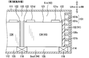
- the battery passage 134 extends in the vertical direction (short direction of the case 110) by a space surrounded by the mutually facing surfaces of the adjacent battery cells 121 and the pair of covers 122 facing each other. It becomes a shape.
- the space surrounded by the imaginary plane (see the dashed line in FIG. 13) in which the inflow port 134a extends in the direction (vertical direction) in which the battery passage 134 extends corresponds to the side space Sin.
- a region of the top wall side passage 133 that overlaps with the inflow port 134a when viewed from the direction in which the battery passage 134 extends corresponds to the inflow side space Sin.
- the inflow side space Sin functions to distribute the fluid in the top wall side passage 133 to each inflow port 134a.
- the space facing the outflow port 134 b of the battery passage 134, and the portion with a halftone dot in FIG. 13 corresponds to the “outflow side space Sout” recited in the claims. . More specifically, a space surrounded by a virtual surface (not shown) in which the outflow port 134b extends in the direction (vertical direction) in which the battery passage 134 extends and the bottom wall 112 is the bottom wall side passage 135. Corresponds to the outflow side space Sout. In other words, a region of the bottom wall side passage 135 that overlaps the outflow port 134b when viewed from the direction in which the battery passage 134 extends corresponds to the outflow side space Sout.
- the outflow side space Sout functions to collect the fluid in the bottom wall side passage 135 from each outflow port 134b.
- the fluid flow velocity V1 in the first and second side wall passages 131 and 132 indicates the fluid flow velocity V1 in the first and second side wall passages 131 and 132.
- the flow velocity measured in the arbitrary places of the 1st and 2nd side wall side passages 131 and 132 be the above-mentioned flow velocity V1.
- the maximum or minimum value of the flow velocity measured at a plurality of locations is set as the flow velocity V1.
- the flow velocity at the fin inlet 151a in the first and second side wall passages 131 and 132 is set as the flow velocity V1.
- the flow velocity in the finless region 131b or the flow velocity in the fin region 131a in the first and second sidewall passages 131 and 132 is set as the flow velocity V1.
- a symbol V2 in FIG. 13 indicates the flow velocity V2 of the fluid in the inflow side space Sin.
- the flow velocity measured at an arbitrary location in the inflow side space Sin is defined as the flow velocity V2.
- the average of the flow velocity measured in several places of inflow side space Sin be the said flow velocity V2.
- the maximum value or the minimum value of the flow velocity measured at a plurality of locations in the inflow side space Sin is set as the flow velocity V2.
- a symbol V ⁇ b> 3 in FIG. 13 indicates the fluid flow velocity V ⁇ b> 3 in the battery passage 134.
- the flow velocity measured at an arbitrary location in the battery passage 134 is set as the flow velocity V3.
- path 134 be the said flow velocity V3.
- the maximum value or the minimum value of the flow velocity measured at a plurality of locations in the battery passage 134 is set as the flow velocity V3.
- the symbol V4 in FIG. 13 indicates the flow velocity V4 of the fluid in the outflow side space Sout.
- the flow velocity measured at an arbitrary location in the outflow space Sout is defined as the flow velocity V4.
- the average of the flow velocity measured in several places of the outflow side space Sout be the said flow velocity V4.
- the maximum value or the minimum value of the flow velocity measured at a plurality of locations in the outflow side space Sout is set as the flow velocity V4.
- the passage cross-sectional area A3 of the top wall side inlet 133a is set larger than the passage cross-sectional area A2 of the first and second side wall side passages 131 and 132. Therefore, the flow velocity V2 of the fluid in the inflow side space Sin is lower than the flow velocity V1 of the fluid in the first and second side wall passages 131 and 132.
- the pressure energy increases by the amount of decrease in the flow velocity energy, and the increase in pressure energy means that the fluid is statically pressurized and the flow distribution is made uniform. Therefore, according to the present embodiment, when the fluid in the top wall side passage 133 is distributed to the plurality of battery passages 134, the distribution variation, that is, the inflow amount distribution variation is reduced.
- the variation in the heat dissipation amount from the battery cell 121 can be reduced, the temperature distribution variation in the battery cell 121 can be reduced, and as a result, it can be promoted that the charging / discharging performance of the entire battery pack 100 is sufficiently exhibited.
- the passage sectional area A5 of the bottom wall side outlet 135a is set larger than the passage sectional area A2 of the first and second sidewall side passages 131 and 132. Therefore, the flow velocity V4 of the fluid in the outflow side space Sout is lower than the flow velocity V1 of the fluid in the first and second side wall passages 131 and 132. This means that the pressure energy increases as the flow velocity energy decreases, and the fluid is statically pressurized and the flow distribution is made uniform. Therefore, according to the present embodiment, when the fluid flowing out from the plurality of battery passages 134 is collected in the bottom wall side passage 135, the distribution variation of the outflow amount from the battery passage 134 is reduced.
- the variation in the heat dissipation amount from the battery cell 121 can be reduced, the temperature distribution variation in the battery cell 121 can be reduced, and as a result, it can be promoted that the charging / discharging performance of the entire battery pack 100 is sufficiently exhibited.
- the cross-sectional area A2 of the first and second side wall-side passages 131 and 132 is set smaller than the other passage cross-sectional areas A3 and A5. Therefore, the fluid in the first and second side wall passages 131 and 132 increases in flow velocity energy by the amount of decrease in pressure energy, and the flow velocity increases as compared with the fluid in the top wall side passage 133 and the bottom wall side passage 135. That is, the flow rate V1 is faster than the flow rates V2 and V3. Therefore, the heat transfer rate when the heat of the fluid moves to the case 110 can be increased, and the amount of heat released from the case 110 to the outside air can be increased.
- first and second side wall-side passages 131 and 132 variation in the flow velocity distribution is promoted as the flow velocity energy increases, but as described above, static pressure is achieved in the top wall-side passage 133 (inflow side space Sin).
- the present embodiment it is possible to achieve both the temperature distribution variation of the battery cell 121 due to the distribution variation to the battery passage 134 and the increase in the heat radiation amount in the first and second side wall passages 131 and 132. .
- the first and second side walls 113 and 114 are provided with first internal fins 151 that exchange heat with the fluid flowing through the first and second side wall passages 131 and 132. Therefore, the heat dissipation amount can be further increased. In particular, since the flow velocity is increased in the first and second side wall passages 131 and 132, the effect of increasing the heat radiation amount by providing the first internal fins 151 is remarkably exhibited.
- the first internal fins 151 are arranged in such a direction as to guide the flow direction of the fluid flowing in the horizontal direction into the first and second side wall passages 131 and 132 to the top wall side passage 133. Specifically, as shown in FIG. 5, the first internal fins 151 are inclined. Therefore, the first internal fins 151 for increasing the heat radiation amount can be used for changing the flow direction of the fluid, and the heat radiation amount can be increased while changing the direction.
- straight fins that extend linearly are employed for the first internal fins 151. Therefore, ventilation resistance can be made small compared with the case where other fins, such as a corrugated fin, are employ
- the area of the fin inlet is equal to the passage cross-sectional area A1. Become. Then, since the area of the fin inlet becomes smaller than that of the fin inlet 151a according to the present embodiment, the number of first internal fins 151 must be reduced. In addition, the high-temperature fluid exchanges heat with the first internal fin 151 in the upstream portion of the first internal fin 151, whereas the low-temperature fluid exchanges heat with the first internal fin 151 in the downstream portion of the first internal fin 151. It will be.
- the temperature difference between the outside air temperature and the fluid temperature is reduced in the downstream portion of the first internal fin 151, and the heat exchange efficiency is deteriorated.
- the length of the first internal fins 151 is longer than that in the case of the inclined arrangement, so that an area with poor heat exchange efficiency increases.
- the first and second side wall-side passages 131 and 132 are positioned on the upstream side of the fin regions 131a and 132a in which the first internal fins 151 are disposed and the fin regions 131a and 132a. It is divided into finless areas 131b and 132b.
- the passage cross-sectional area A2 that is the area of the fin inlet 151a through which fluid flows into the fin regions 131a and 132a is larger than the passage sectional area A1 that is the area of the finless inlet 131c through which fluid flows into the finless regions 131b and 132b. large.
- the passage sectional area A1 is a passage sectional area when the finless regions 131b and 132b are viewed in the inflow direction (horizontal direction) in which the fluid flows into the finless regions 131b and 132b.
- first and second side walls 113 and 114 are rectangular, when the plurality of fin portions of the first internal fin 151 are inclined as described above, the lengths of the fin portions are greatly different. Then, the temperature of the fluid flowing out from the first internal fin 151 varies depending on which fin portion has passed.
- the length of the fin portion of the second internal fin 152 is set to be shorter as the portion of the second internal fin 152 into which the fluid flows from the downstream portion of the first side wall-side passage 131.
- the longer the fin portion of the first inner fin 151 the shorter the corresponding fin portion of the second inner fin 152 is set. Therefore, it is possible to suppress variations in the lengths of the fin portions obtained by adding both the first internal fins 151 and the second internal fins 152. Therefore, temperature variation of the fluid flowing into the battery passage 134 can be suppressed.
- the top wall 111 is formed in a flat plate shape.
- the top wall 111 is provided with a protruding portion 111 a that protrudes toward the top wall side passage 133.
- the protruding portion 111a has a shape extending in the longitudinal direction (front-rear direction) of the first and second side wall-side passages 131 and 132, and is opposed to the entire longitudinal direction of the top wall-side inlet 133a.
- the shape extends along the line 111.
- the longitudinal dimension of the protrusion 111a is set to be equal to or greater than the longitudinal dimension of the ceiling wall inlet 133a.
- the protruding portion 111 a is set in a shape extending over the entire front and rear direction of the top wall 111, one end of the protruding portion 111 a abuts on the third side wall 115, and the other end is the fourth side wall. 116 abuts.
- the top wall 111 is formed of a plate material, and the protruding portion 111a is formed by bending the plate material.
- the protrusion 111a is formed in a shape having a surface parallel to the bottom wall 112 and a surface parallel to the first and second side walls 113 and 114.
- a plurality of protrusions 111a are provided, and the plurality of protrusions 111a are arranged in parallel. In the present embodiment, there are two protrusions 111a.
- the projecting portion 111 a projecting toward the top wall side passage 133 is provided on the top wall 111. According to this, the fluid that has flowed into the ceiling wall side passage 133 from the ceiling wall side inlet 133a collides with the protruding portion 111a and decreases in speed. Therefore, when the fluid in the top wall side passage 133 is distributed to the plurality of battery passages 134, reduction of the distribution variation is promoted.
- the protrusion part 111a is a shape extended along the top wall 111 so that the top wall side inflow port 133a (communication port) may be opposed. Specifically, it opposes over the whole longitudinal direction of the ceiling wall side inflow port 133a. Therefore, the speed reduction can be promoted, and the protrusion 111a functions as a reinforcing member for improving the strength of the top wall 111.
- the protrusion 111a since both ends of the protrusion 111a are in contact with the third and fourth side walls 115 and 116, the function as a reinforcing member can be improved.
- a gap is formed between the tip of the fin portion of the first internal fin 151 and the outer case 121 b of the battery cell 121.
- the sealing material 130s is disposed in the gap.
- the first internal fin 151 includes a substrate portion 151b and a plurality of fin portions 151c, as in the first embodiment.
- the substrate portion 151b is attached in close contact with the first and second side walls 113 and 114.
- the fin portion 151c protrudes from the substrate portion 151b toward the first and second side wall passages 131 and 132.
- a resiliently deformable sealing material 130 s is disposed between the tip of the fin portion 151 c and the outer case 121 b of the battery cell 121.
- the sealing material 130s is arranged in a state of being elastically deformed in the compression direction, and seals between the tip of the fin portion and the exterior case 121b.
- the fin inlet 151a that is the inlet of the fin regions 131a and 132a corresponds to the “passage cross-sectional area A2 of the first and second sidewall-side passages 131 and 132”.
- the fin inflow port 151a according to the first embodiment includes the gap in addition to the inflow port of the first internal fin 151.
- the fin inflow port 151a since the said clearance gap does not exist by providing the sealing material 130s, the fin inflow port 151a corresponds with the inflow port of the 1st internal fin 151.
- the fluid can be supplied to the top wall side inlet 133a without exchanging heat with the first internal fin 151. Can be prevented from flowing in. Therefore, the heat radiation amount from the case 110 to the external air can be increased.
- the gap between the first internal fin 151 and the battery cell 121 is filled with the sealing material 130s.
- the gaps are reduced by bringing the tips of the fin portions 151 c into contact with the cover 122. Therefore, also in the present embodiment, the fin inlet 151a coincides with the inlet of the first internal fin 151 in the same manner as the third embodiment.
- the gap between the first internal fin 151 and the battery cell 121 can be eliminated, so that the fluid flows into the top wall side inlet 133a without exchanging heat with the first internal fin 151. Can be suppressed. Therefore, the heat radiation amount from the case 110 to the external air can be increased.
- the inflow port 134a of the battery passage 134 is specified above the gap.
- the lower part is closed with a cover, leaving the upper part on the side of the gap.
- the inlet of the battery passage 134 includes an inlet 134c positioned on the side in addition to the inlet 134a positioned above the gap.
- the inflow side space Sin according to the present embodiment has a shape in which the inflow side space Sin according to the first embodiment is expanded laterally (see the halftone dots in FIG. 17).
- the magnitude relation of the flow velocity such as V2> V1, V4> V1, V2> V3, V4> V3 is the first.
- the circulation passage 130 is formed so as to be the same as in the first embodiment. Therefore, the same effects as those of the first embodiment are also exhibited by this embodiment.
- the passage sectional area A3 of the top wall side inlet 133a, the passage sectional area A5 of the bottom wall side outlet 135a, and the passage sectional area A2 of the first and second sidewall side passages 131 and 132 Regarding the size comparison with the passage sectional area A4 of the battery passage 134, all of the following magnitude relations are satisfied. That is, it is set to satisfy all four conditions such as A3> A2, A5> A2, A3> A4, and A5> A4.
- the present invention only needs to be set to satisfy at least one of these four conditions, and is not limited to a setting that satisfies all four conditions.
- any of A5> A3, A5 ⁇ A3 and A5 A3 may be used.
- any of A4> A2, A4 ⁇ A2 and A4 A2 may be used.
- the top wall 111 is bent to form the protruding portion 111a.
- the protrusion 111a may be formed by a member different from the top wall 111, and the protrusion 111a may be attached to the top wall 111.
- the projecting portion 111a is formed in a shape extending along the top wall with a length facing the entire longitudinal direction of the top wall side inflow port 133a.
- the protrusions 111a may be formed shorter than the above length, or a plurality of pin-shaped protrusions 111a may be arranged in parallel in the longitudinal direction of the top wall side inlet 133a.
- the protrusion part 111a may be abolished.
- the first internal fins 151 are inclined so as to guide the flow direction of the fluid flowing in the horizontal direction into the first and second side wall passages 131 and 132 to the top wall side passage 133.
- the 1st internal fin 151 may be horizontally arrange
- the fluid flowing through the first and second side wall passages 131 and 132 changes the direction upward after flowing through the first internal fins 151 and flows into the top wall side inlet 133a.
- at least one of the first internal fin 151 and the second internal fin 152 may be abolished.
- the first internal fin 151 and the second internal fin 152 are not limited to straight fins, and may be, for example, pin-shaped fins or corrugated fins.
- the battery pack 100 of the said 1st Embodiment was made to circulate a fluid to the circulation channel
- the fluid may be circulated through the circulation passage 130.
- an axial fan, a turbo fan, or the like can be used in addition to the sirocco fan described in the first embodiment.
- the PTC heater 144 is not limited to the inside of the fan casing 143 but may be provided inside the case 110 and outside the fan casing 143.
- the inner fin and the outer fin in each of the above-described embodiments may be those in which fins that are separate parts are fixed to the wall of the case 110, or a part of the wall of the case 110 is formed in a fin shape to form a fin It may be a thing.
- the tip of the fin portion 151c is brought into contact with the cover 122, but may be brought into contact with the outer case 121b of the battery cell 121.
- the inflow side space Sin is defined as a space facing the inflow port 134a of the battery passage 134.
- a space in which the space facing the inlet 134a of the battery passage 134 is connected and expanded in the stacking direction of the cell stack 120A (the vertical direction in FIG. 13) is defined as an inflow side space Sin.
- the space above the cell stack 120A in the top wall side passage 133 may be defined as the inflow side space Sin.
- the plurality of cell stacks 120A are accommodated in the case 110.
- the space expanded by connecting the space above each cell stack 120A is defined as the inflow side space Sin. May be.
- the outflow side space Sout is defined as a space facing the outflow port 134b of the battery passage 134.
- the space where the space facing the outflow port 134b of the battery passage 134 is connected and expanded in the stacking direction of the cell stack 120A (the vertical direction in FIG. 13) is defined as the outflow side space Sout.
- the space below the cell stack 120A in the bottom wall side passage 135 may be defined as the outflow side space Sout.
- the case 110 forms a hexahedron and a rectangular parallelepiped, but the casing included in the invention is not limited to this shape.
- the case 110 may be a polyhedron having more than six surfaces, or at least one surface may include a curved surface.
- the case 110 may be formed in a dome shape in which the top wall includes a curved surface, or the casing may have a trapezoidal vertical cross-sectional shape.
- the top wall is a wall having a positional relationship facing the bottom wall, and the shape thereof may include any of a flat surface and a curved surface.
- the side wall may be a wall extending from the bottom wall in a direction intersecting the bottom wall, or may be a wall extending from the top wall in a direction intersecting the top wall.
- the boundary between the top wall and the side wall in the case 110 may form a corner or a curved surface.
- the boundary between the bottom wall and the side wall in the case 110 may form a corner or a curved surface.
- the number of cell stacks 120A included in the battery pack is four, but the number is not limited thereto.
- the cell stack 120A when only one cell stack 120A included in the battery pack is accommodated inside the casing, or when a plurality of cell stacks 120A are installed side by side in one direction, the cell stack 120A also extends in another direction that intersects the one direction. This includes cases where a plurality of the devices are installed side by side.
- the cell stack 120A is arranged in the casing in a direction in which the positive terminal 121c and the negative terminal 121d face the top wall 111.
- the cell stack 120A may be arranged in a direction in which the positive electrode terminal 121c and the negative electrode terminal 121d face the first and second side walls 113 and 114.
Landscapes
- Chemical & Material Sciences (AREA)
- Chemical Kinetics & Catalysis (AREA)
- Electrochemistry (AREA)
- General Chemical & Material Sciences (AREA)
- Engineering & Computer Science (AREA)
- Manufacturing & Machinery (AREA)
- Secondary Cells (AREA)
- Battery Mounting, Suspending (AREA)
Priority Applications (1)
| Application Number | Priority Date | Filing Date | Title |
|---|---|---|---|
| US15/750,868 US10950907B2 (en) | 2015-08-07 | 2016-08-01 | Battery pack |
Applications Claiming Priority (2)
| Application Number | Priority Date | Filing Date | Title |
|---|---|---|---|
| JP2015-157252 | 2015-08-07 | ||
| JP2015157252A JP6330757B2 (ja) | 2015-08-07 | 2015-08-07 | 電池パック |
Publications (1)
| Publication Number | Publication Date |
|---|---|
| WO2017026312A1 true WO2017026312A1 (ja) | 2017-02-16 |
Family
ID=57983703
Family Applications (1)
| Application Number | Title | Priority Date | Filing Date |
|---|---|---|---|
| PCT/JP2016/072495 Ceased WO2017026312A1 (ja) | 2015-08-07 | 2016-08-01 | 電池パック |
Country Status (3)
| Country | Link |
|---|---|
| US (1) | US10950907B2 (https=) |
| JP (1) | JP6330757B2 (https=) |
| WO (1) | WO2017026312A1 (https=) |
Cited By (7)
| Publication number | Priority date | Publication date | Assignee | Title |
|---|---|---|---|---|
| DE102017211534A1 (de) * | 2017-07-06 | 2019-01-10 | Robert Bosch Gmbh | Stationärer Energiespeicher |
| DE102018219250A1 (de) | 2018-11-12 | 2020-05-14 | Mahle Lnternational Gmbh | Akkumulatoranordnung |
| DE102018219249A1 (de) | 2018-11-12 | 2020-05-14 | Mahle Lnternational Gmbh | Akkumulatoranordnung |
| WO2022030449A1 (ja) * | 2020-08-07 | 2022-02-10 | 株式会社Gsユアサ | 蓄電装置 |
| DE102022209744A1 (de) | 2022-09-16 | 2024-03-21 | Mahle International Gmbh | Akkumulatoranordnung |
| WO2025141695A1 (ja) * | 2023-12-26 | 2025-07-03 | 日産自動車株式会社 | 車両構造 |
| WO2025141696A1 (ja) * | 2023-12-26 | 2025-07-03 | 日産自動車株式会社 | 車両構造 |
Families Citing this family (3)
| Publication number | Priority date | Publication date | Assignee | Title |
|---|---|---|---|---|
| DE102016208053B4 (de) * | 2016-05-10 | 2023-12-21 | Bayerische Motoren Werke Aktiengesellschaft | Fahrzeug mit einem Hochvoltspeicher |
| JP7107247B2 (ja) * | 2019-02-22 | 2022-07-27 | 株式会社デンソー | 電池モジュール |
| JP7473575B2 (ja) * | 2022-03-18 | 2024-04-23 | 本田技研工業株式会社 | バッテリカバー、およびバッテリカバー組立体 |
Citations (5)
| Publication number | Priority date | Publication date | Assignee | Title |
|---|---|---|---|---|
| JPH08310256A (ja) * | 1995-05-19 | 1996-11-26 | Nissan Motor Co Ltd | 電気自動車のバッテリフレーム構造 |
| JP2002313440A (ja) * | 2001-04-13 | 2002-10-25 | Nissan Motor Co Ltd | 電気自動車のバッテリ冷却装置 |
| JP2013191305A (ja) * | 2012-03-12 | 2013-09-26 | Toyota Industries Corp | 電池パック |
| JP2013244861A (ja) * | 2012-05-28 | 2013-12-09 | Mazda Motor Corp | 車両用バッテリユニットの空調構造 |
| JP2015032429A (ja) * | 2013-08-01 | 2015-02-16 | 株式会社デンソー | 電池冷却装置 |
Family Cites Families (8)
| Publication number | Priority date | Publication date | Assignee | Title |
|---|---|---|---|---|
| JP2009170370A (ja) | 2008-01-18 | 2009-07-30 | Toyota Motor Corp | 温度調節機構 |
| JP5130955B2 (ja) | 2008-02-29 | 2013-01-30 | 日産自動車株式会社 | 組電池 |
| JP2010015955A (ja) | 2008-07-07 | 2010-01-21 | Toyota Motor Corp | 蓄電装置 |
| JP5768994B2 (ja) | 2008-11-17 | 2015-08-26 | カルソニックカンセイ株式会社 | 車両用バッテリー冷却システム |
| WO2011040130A1 (ja) * | 2009-09-30 | 2011-04-07 | 株式会社 日立製作所 | 蓄電モジュール |
| JP5842867B2 (ja) | 2013-06-03 | 2016-01-13 | 株式会社デンソー | 電池冷却装置 |
| US9780413B2 (en) | 2013-08-01 | 2017-10-03 | Denso Corporation | Battery cooling system |
| JP6149610B2 (ja) | 2013-08-28 | 2017-06-21 | 株式会社デンソー | 電池冷却装置 |
-
2015
- 2015-08-07 JP JP2015157252A patent/JP6330757B2/ja active Active
-
2016
- 2016-08-01 WO PCT/JP2016/072495 patent/WO2017026312A1/ja not_active Ceased
- 2016-08-01 US US15/750,868 patent/US10950907B2/en active Active
Patent Citations (5)
| Publication number | Priority date | Publication date | Assignee | Title |
|---|---|---|---|---|
| JPH08310256A (ja) * | 1995-05-19 | 1996-11-26 | Nissan Motor Co Ltd | 電気自動車のバッテリフレーム構造 |
| JP2002313440A (ja) * | 2001-04-13 | 2002-10-25 | Nissan Motor Co Ltd | 電気自動車のバッテリ冷却装置 |
| JP2013191305A (ja) * | 2012-03-12 | 2013-09-26 | Toyota Industries Corp | 電池パック |
| JP2013244861A (ja) * | 2012-05-28 | 2013-12-09 | Mazda Motor Corp | 車両用バッテリユニットの空調構造 |
| JP2015032429A (ja) * | 2013-08-01 | 2015-02-16 | 株式会社デンソー | 電池冷却装置 |
Cited By (7)
| Publication number | Priority date | Publication date | Assignee | Title |
|---|---|---|---|---|
| DE102017211534A1 (de) * | 2017-07-06 | 2019-01-10 | Robert Bosch Gmbh | Stationärer Energiespeicher |
| DE102018219250A1 (de) | 2018-11-12 | 2020-05-14 | Mahle Lnternational Gmbh | Akkumulatoranordnung |
| DE102018219249A1 (de) | 2018-11-12 | 2020-05-14 | Mahle Lnternational Gmbh | Akkumulatoranordnung |
| WO2022030449A1 (ja) * | 2020-08-07 | 2022-02-10 | 株式会社Gsユアサ | 蓄電装置 |
| DE102022209744A1 (de) | 2022-09-16 | 2024-03-21 | Mahle International Gmbh | Akkumulatoranordnung |
| WO2025141695A1 (ja) * | 2023-12-26 | 2025-07-03 | 日産自動車株式会社 | 車両構造 |
| WO2025141696A1 (ja) * | 2023-12-26 | 2025-07-03 | 日産自動車株式会社 | 車両構造 |
Also Published As
| Publication number | Publication date |
|---|---|
| JP2017037750A (ja) | 2017-02-16 |
| US10950907B2 (en) | 2021-03-16 |
| JP6330757B2 (ja) | 2018-05-30 |
| US20180241106A1 (en) | 2018-08-23 |
Similar Documents
| Publication | Publication Date | Title |
|---|---|---|
| JP6330757B2 (ja) | 電池パック | |
| JP6384423B2 (ja) | 電池パック | |
| JP6390550B2 (ja) | 電池パック | |
| CN107851868B (zh) | 电池组 | |
| JP6308188B2 (ja) | 電池パック | |
| JP6256439B2 (ja) | 電池パック | |
| US10411312B2 (en) | Battery pack | |
| JP5285489B2 (ja) | 組電池装置 | |
| JP6390548B2 (ja) | 電池パック | |
| JP6507920B2 (ja) | 電池パック | |
| JP6493166B2 (ja) | 電池パック | |
| JP5835394B2 (ja) | 電池冷却装置 | |
| JP6507921B2 (ja) | 電池パック | |
| JP4698344B2 (ja) | 組電池 | |
| JP6458709B2 (ja) | 電池パック | |
| JP6507951B2 (ja) | 電池パック | |
| JP2015028885A (ja) | 電池冷却装置 | |
| JP6519443B2 (ja) | 電池パック | |
| JP6443298B2 (ja) | 電池パック | |
| JP7528890B2 (ja) | 電池パック |
Legal Events
| Date | Code | Title | Description |
|---|---|---|---|
| 121 | Ep: the epo has been informed by wipo that ep was designated in this application |
Ref document number: 16835009 Country of ref document: EP Kind code of ref document: A1 |
|
| WWE | Wipo information: entry into national phase |
Ref document number: 15750868 Country of ref document: US |
|
| NENP | Non-entry into the national phase |
Ref country code: DE |
|
| 122 | Ep: pct application non-entry in european phase |
Ref document number: 16835009 Country of ref document: EP Kind code of ref document: A1 |