WO2017018191A1 - 加湿装置 - Google Patents
加湿装置 Download PDFInfo
- Publication number
- WO2017018191A1 WO2017018191A1 PCT/JP2016/070485 JP2016070485W WO2017018191A1 WO 2017018191 A1 WO2017018191 A1 WO 2017018191A1 JP 2016070485 W JP2016070485 W JP 2016070485W WO 2017018191 A1 WO2017018191 A1 WO 2017018191A1
- Authority
- WO
- WIPO (PCT)
- Prior art keywords
- air
- adsorbent
- ceiling
- moisture
- space
- Prior art date
Links
Images


Classifications
-
- B—PERFORMING OPERATIONS; TRANSPORTING
- B60—VEHICLES IN GENERAL
- B60H—ARRANGEMENTS OF HEATING, COOLING, VENTILATING OR OTHER AIR-TREATING DEVICES SPECIALLY ADAPTED FOR PASSENGER OR GOODS SPACES OF VEHICLES
- B60H3/00—Other air-treating devices
- B60H3/02—Moistening ; Devices influencing humidity levels, i.e. humidity control
- B60H3/022—Moistening ; Devices influencing humidity levels, i.e. humidity control for only humidifying the air
-
- B—PERFORMING OPERATIONS; TRANSPORTING
- B60—VEHICLES IN GENERAL
- B60H—ARRANGEMENTS OF HEATING, COOLING, VENTILATING OR OTHER AIR-TREATING DEVICES SPECIALLY ADAPTED FOR PASSENGER OR GOODS SPACES OF VEHICLES
- B60H1/00—Heating, cooling or ventilating [HVAC] devices
- B60H1/00007—Combined heating, ventilating, or cooling devices
- B60H1/00207—Combined heating, ventilating, or cooling devices characterised by the position of the HVAC devices with respect to the passenger compartment
- B60H2001/00235—Devices in the roof area of the passenger compartment
-
- B—PERFORMING OPERATIONS; TRANSPORTING
- B60—VEHICLES IN GENERAL
- B60H—ARRANGEMENTS OF HEATING, COOLING, VENTILATING OR OTHER AIR-TREATING DEVICES SPECIALLY ADAPTED FOR PASSENGER OR GOODS SPACES OF VEHICLES
- B60H3/00—Other air-treating devices
- B60H3/02—Moistening ; Devices influencing humidity levels, i.e. humidity control
- B60H2003/026—Moistening ; Devices influencing humidity levels, i.e. humidity control the devices being located in the passenger compartment
-
- B—PERFORMING OPERATIONS; TRANSPORTING
- B60—VEHICLES IN GENERAL
- B60H—ARRANGEMENTS OF HEATING, COOLING, VENTILATING OR OTHER AIR-TREATING DEVICES SPECIALLY ADAPTED FOR PASSENGER OR GOODS SPACES OF VEHICLES
- B60H3/00—Other air-treating devices
- B60H3/02—Moistening ; Devices influencing humidity levels, i.e. humidity control
- B60H2003/028—Moistening ; Devices influencing humidity levels, i.e. humidity control the devices comprising regeneration means
Definitions
- the present disclosure relates to a humidifying device that provides humidified air to a room.
- Patent Document 1 discloses a form of a humidifying device that supplies humidified air to passengers in a vehicle interior.
- the humidifier operates a pair of blowers, sucks air in the vehicle compartment from the suction port, and passes the air through the pair of adsorbents.
- the air passing through each adsorbent is dehumidified air by moisture adsorbed by the adsorbent.
- the dehumidified air is guided to the first air outlet and the second air outlet by the switching damper, and is blown out from the first air outlet toward the front window and from the second air outlet toward the occupant.
- the humidifier When the humidifier blows humidified air, the humidifier operates only one heater and a pair of blowers, sucks the air in the passenger compartment from the inlet and passes it through the pair of adsorbents.
- One adsorbent is heated by the heater and released to the air passing through the adsorbed moisture. Therefore, the air passing through one adsorbent becomes humidified air containing moisture released from the adsorbent.
- the humidified air is guided to the second air outlet by the switching damper and is blown out from the second air outlet toward the occupant. Further, since the other adsorbent is not heated by the heater, the air passing through the other adsorbent is adsorbed by the adsorbent and becomes dehumidified air.
- the dehumidified air is guided to the first air outlet by the switching damper and blown out from the first air outlet toward the front window.
- Patent Document 1 For example, in the winter season when humidification is required, the passenger compartment is heated, so the air in the passenger compartment is dried due to a decrease in relative humidity.
- the apparatus of Patent Document 1 is a so-called desiccant system that takes in air in a passenger compartment, collects moisture in the air, and uses it when supplying humidified air thereafter. Therefore, the water necessary for humidification cannot be recovered, and there is a possibility that sufficient humidification ability cannot be ensured.
- This indication is made in view of the above-mentioned point, and it aims at providing the humidification device which aims at suppression of the humidification capability fall by vehicle interior heating.
- the humidifier according to the first aspect of the present disclosure is a vehicle humidifier that supplies humidified air humidified by moisture desorbed from an adsorbent that has adsorbed moisture in the air to the vehicle interior.
- the humidifier includes an adsorbent module and a blower.
- the adsorbent module has an adsorbent, and adsorbs moisture contained in the passing air to the adsorbent or desorbs the moisture adsorbed on the adsorbent from the air passing through.
- the blower blows the passing air to the adsorbent module.
- the air blowing unit takes in air in the ceiling space formed between the vehicle top plate and the ceiling interior member in the vehicle interior, and the air is supplied to the adsorbent module. The air is blown to adsorb moisture in the air with the adsorbent.
- the moisture contained in the air in the ceiling space defined between the vehicle top plate and the ceiling interior member in the passenger compartment is adsorbed by the adsorbent, so that the relative humidity is increased by heating.
- Moisture can be recovered from air that is less affected by heating than the air in the passenger compartment. Accordingly, it is possible to perform adsorption with higher moisture collection efficiency than to collect moisture from the air in the heated vehicle compartment, and it is possible to provide humidified air that secures the humidifying capacity at the next desorption. Therefore, it is possible to provide a humidifier that can suppress a decrease in humidification capacity due to vehicle interior heating.
- the humidifying device is a humidifying device for a vehicle that supplies humidified air that has been humidified by moisture desorbed from an adsorbent that has adsorbed moisture in the air to a humidification target space.
- the humidifier includes an adsorbent module and a blower.
- the adsorbent module has an adsorbent, and adsorbs moisture contained in the passing air to the adsorbent, and desorbs moisture adsorbed on the adsorbent to the passing air.
- the blower blows the passing air to the adsorbent module.
- the blower unit takes in air outside the vehicle, blows the air to the adsorbent module, and adsorbs moisture in the air with the adsorbent.
- the humidification apparatus which can aim at suppression of the humidification capability fall by vehicle interior heating can be provided also by the 2nd mode.
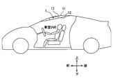
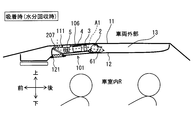
- FIG. 1 It is a schematic diagram which shows the position where the humidification apparatus which concerns on 1st Embodiment is mounted in a vehicle. It is sectional drawing which shows the general
- the humidifying device of the present disclosure is mounted on the back side of the ceiling interior member 12 in the vehicle interior R, and the vehicle interior R is used as a humidification target space.
- the humidifier disclosed in each embodiment sets the vehicle interior R as a humidification target space.
- the vehicle on which the humidifier 1 is mounted includes a vehicle air conditioner that adjusts the temperature of the passenger compartment R.
- the humidifier 1 is installed in a ceiling space 13 that is partitioned between a vehicle top plate 11 and a ceiling interior member 12.
- the ceiling interior space 13 is partitioned from the vehicle interior R by the ceiling interior member 12. Since the ceiling interior space 13 is a predetermined space defined between the vehicle top plate 11 and the ceiling interior member 12, it is not a space that is completely blocked from the vehicle interior R. Depending on the pressure difference between the ceiling space 13 and the vehicle interior R, some air may enter and leave the ceiling space 13 through a gap between members.
- the up and down arrows shown in each figure indicate directions in a state where the humidifying device 1 is mounted on the vehicle. Therefore, the upper side and the lower side are the upper side and the lower side in the vertical direction of the vehicle, respectively, and the front side and the rear side are the front side and the rear side in the front and rear direction of the vehicle, respectively.
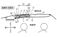
- the humidifier 1 accommodates a blower 2, a heating device 3, an adsorbent module 4, a cooling device 5 and the like inside a casing 6 that forms an outer shell thereof.
- the blower 2, the heating device 3, the adsorbent module 4, and the cooling device 5 are arranged in this order in the direction A ⁇ b> 2 in which air flows when desorbing moisture from the adsorption element. Is installed. Accordingly, the air introduced into the ceiling space 13 from the first opening 61 at the time of desorption is heated by the heating device 3, passes through the adsorbent module 4, and is added with moisture, and the cooling device 5. After being cooled, the air is blown into the vehicle interior R from the vehicle interior outlet.
- the vehicle interior outlet is referred to as the outlet 121.
- the flow of air at the time of desorption is indicated by solid arrows in FIG.
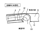
- the humidifying device 1 is arranged in the order of the cooling device 5, the adsorbent module 4, the heating device 3, and the blower 2 in the direction A ⁇ b> 1 in which air flows when adsorbing moisture to the adsorption element. is set up. Therefore, the air introduced into the ceiling space 13 from the second opening 62 at the time of adsorption is cooled by the cooling device 5 and then passes through the adsorbent module 4 to release moisture to the adsorbent. After being heated at 3, the air is blown out from the first opening 61 into the ceiling space 13. The flow of air at the time of adsorption is indicated by broken-line arrows in FIG.
- the first opening 61 is formed in the casing 6 which is an apparatus case, and is a desorption inlet for sucking air in the ceiling space 13 into the casing 6 during desorption.
- the first opening 61 is also a suction outlet for discharging the air after moisture is adsorbed by the adsorbent (air after moisture recovery) to the ceiling space 13 during adsorption.
- the first opening 61 as the desorption inlet port enables air to be taken into the ceiling space 13 by the blower 2 and the air to be blown to the adsorbent module 4 at the time of desorption.
- the second opening 62 is formed in the casing 6 and is a suction inlet portion that sucks air in the ceiling space 13 into the casing 6 during suction.
- the first opening 61 is provided on the opposite side of the casing 6 from the second opening 62.
- the first opening 61 is provided at the rear end of the casing 6, and the second opening 62 is provided at the front end of the casing 6.
- the air blower 2 is provided in the vicinity position adjacent to the 1st opening part 61 which is a discharge port part at the time of adsorption
- the air outlet 121 opens toward the lower passenger compartment R and forms a passage that penetrates the casing 6 and the ceiling interior member 12.
- the air outlet 121 is provided, for example, so as to open above an occupant seated in the front seat of the passenger compartment R.
- a sun visor is provided at a location that is located forward of the air outlet portion 121 in the ceiling interior member 12. It is preferable that a filter that collects dust, dust, and the like carried together with air is installed at the outlet 121.
- a switching door 7 as a switching member is provided in the second opening 62 (suction port at the time of adsorption).
- the switching door 7 allows air to be taken into the space 13 in the ceiling at the time of adsorption in which moisture in the air is adsorbed by the adsorbent, and desorbs from the air passing through the moisture adsorbed by the adsorbent.
- the air that has passed through the adsorbent module 4 is supplied to the vehicle interior R.
- the second opening 62 is provided at a location adjacent to the air outlet 121, and the second opening 62 and the air outlet 121 are switched between an open state and a closed state by the switching door 7.
- the switching door 7 is controlled by the control device so as to close the second opening 62 and open the air outlet 121 when desorbing, and close the air outlet 121 and open the second opening 62 during adsorption. Accordingly, the switching door 7 is provided at the front end of the casing 6 so as to be positioned in front of the cooling device 5 in the casing 6.
- the blower 2 is installed at a position closer to the first opening 61 than other devices, but the installation position of the blower 2 is not limited to this position. Therefore, the blower 2 can be installed at an arbitrary position in the air passage formed between the first opening 61 and the second opening 62.
- the blower 2 is, for example, an electric blower that rotationally drives an axial fan with an electric motor, and constitutes a blower that blows air that passes through the adsorbent module 4.
- the blower 2 can switch the flow direction of the air blown by the blower 2 to the opposite direction by switching the rotation direction of the electric motor by the control device.
- the blower 2 is a blower unit in which the operating rate, that is, the rotation speed and the amount of air to be blown are controlled by a control voltage output from the control device.
- the volume occupied by the amount of air blown into the vehicle interior R during humidification is set to be smaller than the volume of the ceiling space 13.
- the volume occupied by the blown air volume for one time at the time of humidification is about 0.167 m 3 .
- the ceiling space 13 is set to have a volume larger than about 0.167 m 3 .
- the second opening 62 which is the suction port at the time of adsorption, is separated from the peripheral edge of the ceiling interior member 12 where the vehicle top plate 11 and the ceiling interior member 12 can come into contact.
- the second opening 62 has a distance between the second opening 62 and the peripheral edge of the ceiling interior member 12 between the second opening 62 and the first opening 61. It is preferable that the ceiling interior member 12 is separated from the peripheral edge so as to be longer than the distance between them.
- the peripheral part of the ceiling interior member 12 and the vehicle top plate 11 are also seams that define the space 13 in the ceiling. Since the first opening 61 is located not in the vicinity of the peripheral edge of the ceiling interior member 12 but in a separated position, the air in the vehicle interior R drawn into the ceiling interior space 13 during humidification can be brought into contact with the vehicle top plate 11. it can. In winter, for example, the outside air temperature is 0 ° C., the air temperature in the ceiling space 13 is 18 ° C., the relative humidity is 30%, the air temperature in the passenger compartment R is 25 ° C., and the relative humidity is 15%. is there. As shown in FIG. 2, during humidification, the air in the passenger compartment R drawn into the ceiling interior space 13 is cooled by contacting the vehicle top plate 11. Therefore, the relative humidity of the air before reaching the adsorbent module 4 can be increased, and the relative humidity of the humidified air can be further increased. This effect is particularly remarkable in winter when the outside air temperature is low.
- Air in the ceiling interior space 13 is sucked into the air passage in the casing 6 from the second opening 62, flows in the order of the cooling device 5, the adsorbent module 4, and the heating device 3, and becomes dehumidified air in the first opening. 61 is blown out into the ceiling space 13.
- the air in the ceiling space 13 is sucked into the casing 6 and is blown out into the ceiling space 13 after the water is collected, so that the ceiling space 13 does not become a negative pressure with respect to the vehicle interior R. Thereby, the air in the vehicle interior R is not drawn into the ceiling interior space 13 through the gap between the vehicle top plate 11 and the ceiling interior member 12.
- the casing 6 is formed in a box shape with resin or metal, and forms an air passage through which air blown from the blower 2 is circulated.
- the casing 6 is formed in a thin rectangular parallelepiped shape extending along the vehicle top plate 11 and the ceiling interior member 12.
- the adsorbent module 4 is configured by laminating and arranging a plurality of metal plate-like members carrying adsorbents at intervals. Therefore, a passage through which air passes is formed between adjacent plate-like members.
- the contact area between air and the adsorbent can be increased by arranging a plurality of plate-like members carrying the adsorbent in this way.
- the adsorbing material a polymeric adsorbing material or a hygroscopic material such as zero light, which is a polyhedron obtained by drying gelatinous soft mud, is employed.
- the heating device 3 is a heater capable of heating the air flowing through the air passage in the casing 6.
- the heating device 3 can employ various methods as the heating method as long as it can heat the air.
- a device having a heating element that generates heat when energized, or a device that heats indoor air by exchanging heat between a medium and air that is higher in temperature than indoor air can be used.
- the heating device 3 is, for example, a device having a nichrome wire heater, a PTC (Positive Temperature Coefficient) heater, a heat exchanger, or the like.
- a heating element such as hot water, a refrigerant, engine cooling water, or an electronic component that generates heat in the vehicle can be used as a medium having a temperature higher than that of air used in the heat exchanger.
- the cooling device 5 is a cooler capable of cooling the air flowing through the air passage in the casing 6. As long as the cooling device 5 can cool the air, various methods can be adopted as the cooling method.
- a heat sink capable of conducting heat with the vehicle top plate 11 can be used.
- the cooling device 5 may be a device having a Peltier element that absorbs heat when energized, or a device that cools indoor air by exchanging heat between a medium and air having a temperature lower than that of the indoor air.
- the cooling device 5 can be a heat exchanger through which a low-temperature medium flows. As a medium having a temperature lower than that of air used for the heat exchanger, outside air, conditioned air, a refrigerant flowing through a refrigeration cycle used for an air conditioner, or the like can be employed.
- a heat exchanger using outside air as a low-temperature medium has a heat sink.
- the heat sink is a heat transfer member having a plurality of fins formed of a metal such as aluminum or copper having excellent heat transfer properties.
- the heat sink is attached to the vehicle top plate 11, for example.
- the heat sink performs a function of transferring heat of outside air outside the vehicle to the air passage in the casing 6.
- the heat sink can exchange heat between the outside air outside the vehicle and the air flowing through the air passage in the casing 6.
- the heat sink is a cooler that cools the air by allowing the cool air that the outside air cools to air that blows into the vehicle interior R, or a cooler that cools the air by dissipating the heat that the air has to the outside air.
- the control device is composed of a microcomputer including a CPU, a ROM, a RAM and the like and its peripheral circuits, and controls the operation of the blower 2 and the switching door 7 connected to the output side. Further, the control device may control a heating action or a cooling action by the heating device 3 or the cooling device 5.
- the input side of the control device is connected to an inside air sensor as an inside air temperature detecting unit for detecting the air temperature in the vehicle interior R, an outside air sensor as an outside air temperature detecting unit for detecting the outside air temperature, and the like. Detection signals from these sensors are input to the control device. Further, an operation switch for operating the humidifying device 1 is connected to the input side of the control device, and operation signals of these switches are input to the control device.
- control device may be configured integrally with, for example, an air conditioning control device that controls the operation of each component device of the vehicle air conditioning device. Further, this control device may be separate from the air conditioning control device, and may communicate information regarding the control state of the device to be controlled.
- the humidifier 1 operates when the operation switch is turned on by the operation of the occupant in a state where the temperature of the vehicle interior R is adjusted by the vehicle air conditioner.
- the humidifier 1 is operated when the outside air temperature is relatively low and the vehicle interior R is easy to dry, such as in winter.
- the control device causes the electric motor of the blower 2 to rotate forward and the switching door 7 opens the blowout port 121, reverses the electric motor, and switches the switching door 7. Switches the state of opening the second opening 62 alternately, for example, every predetermined time.
- the ventilation path at the time of desorption in which air flows as shown by the solid line arrow in FIG. 2 and the ventilation path at the time of adsorption as shown by the broken line arrow in FIG. 3 are switched every predetermined time.
- the control device rotates the electric motor of the blower 2 in the normal direction and controls the switching door 7 so as to open the air outlet 121.
- air having a temperature of 18 ° C. and a relative humidity of 30% in the ceiling space 13 is sucked into the casing 6 through the first opening 61.
- the air sucked into the air passage in the casing 6 is heated when passing through the heating device 3.
- the control device operates the heating device 3 at a constant output so that the temperature of the air after passing through the heating device 3 is higher than the temperature of the air in the ceiling space 13 by a predetermined temperature, for example, about 5 ° C.
- the output of the heating device 3 is controlled according to the temperature change of the air. Therefore, the temperature of the air after passing through the heating device 3 rises to about 23 ° C.
- the air after passing through the heating device 3 flows into the adsorbent module 4.
- the relative humidity of the air whose temperature has increased through the heating device 3 is lower than the relative humidity of the air in the ceiling space 13. Therefore, when the air whose relative humidity has decreased after passing through the heating device 3 is brought into contact with the adsorbent of the adsorbent module 4, the water adsorbed on the adsorbent is easily desorbed into the air. That is, the air whose relative humidity has been lowered by the heating device 3 tends to contain moisture held by the adsorbent, and the air after flowing out of the adsorbent module 4 becomes humidified air that has been sufficiently humidified.
- this humidified air is further cooled by the cooling device 5, the temperature of the humidified air whose temperature has been increased by the heating device 3 decreases. Thereby, it can provide toward a passenger
- the temperature of the air can be quickly raised. Furthermore, since the relative humidity of the air can be lowered quickly due to the rapid rise in air temperature, moisture desorption in the adsorbent module 4 is actively performed, and the air after flowing out of the adsorbent module 4 The relative humidity can be increased quickly.
- the control device reverses the electric motor of the blower 2 and controls the switching door 7 so as to open the second opening 62
- the temperature in the ceiling space 13 is 18 ° C. and the relative humidity is 30%. Air is sucked into the casing 6 through the second opening 62. The air sucked into the air passage in the casing 6 is cooled when passing through the cooling device 5.
- the air after passing through the cooling device 5 flows into the adsorbent module 4.
- the relative humidity of the air whose temperature has decreased after passing through the cooling device 5 is higher than the relative humidity of the air in the ceiling space 13.
- the humidifying device 1 may be configured such that when the air is taken into the casing 6 at the time of desorption, the air in the vehicle interior R is taken in.
- the first opening 161 provided in the vicinity of the blower 2 in the casing 6 opens toward the vehicle interior R to communicate the interior of the casing 6 and the vehicle interior R. Configure the passage.
- the air after moisture collection at the time of adsorption may be discharged into the vehicle interior R.
- the check valve 107 ⁇ / b> A allows the flow of air flowing into the casing 6 from the ceiling interior space 13 through the second opening 62, and the ceiling interior space 13 from the interior of the casing 6. It has a valve function to block the flow of air flowing out to Accordingly, the check valve 107A is elastically deformed into the shape illustrated by the broken line in FIG. 5 to allow the air flow in the direction A1 during the adsorption, and has the shape illustrated by the solid line in FIG. The air leakage from the inside of the casing 6 to the ceiling space 13 during detachment is prohibited.
- the check valve 107 ⁇ / b> B allows the flow of air flowing out of the casing 6 into the vehicle interior R at the air outlet 121, and allows the air flowing into the casing 6 from the vehicle interior R into the casing 6.
- the check valve 107B is elastically deformed into a shape illustrated by a solid line in FIG. 5 to allow an air flow in the direction A2 during detachment, and has a shape illustrated by a broken line in FIG. To prevent air leakage from the casing 6 to the vehicle interior R during adsorption.
- the humidifier 1 is a vehicular humidifier that supplies humidified air humidified by moisture desorbed from an adsorbent that has adsorbed moisture in the air to the vehicle interior R.
- the humidifier 1 has an adsorbent, and adsorbent module 4 that adsorbs moisture contained in the passing air to the adsorbent and desorbs moisture adsorbed on the adsorbent to the air passing through the adsorbent.
- a blower 2 that blows air to the adsorbent module 4.
- the blower 2 takes in the air in the ceiling space 13 defined between the vehicle top plate 11 and the ceiling interior member 12 and sucks the air to the adsorbent module 4 at the time of adsorption. To adsorb moisture in the air.
- the casing 6 of the humidifier 1 is installed in the ceiling space 13.
- the blower 2 takes air in the ceiling space 13 from the suction inlet provided in the casing 6 and blows the air to the adsorbent module 4.
- the casing 6 that accommodates the functional components of the humidifying device 1 is accommodated in the ceiling interior space 13 and the suction port portion at the time of adsorption is provided in the casing 6, the device does not jump into the vehicle interior R, It is possible to provide a humidifier that is compact in terms of mounting.
- the blower 2 sucks air in the ceiling space 13 when adsorbing and adsorbs moisture with the adsorbent, and then discharges it to the ceiling space 13, and takes in the air in the ceiling space 13 when desorbing, The air is blown to the adsorbent module 4.
- the air in the ceiling space 13 is sucked and the moisture in the air is collected and then discharged to the ceiling space 13, so that the ceiling space 13 does not become negative pressure. Therefore, it can suppress that the air of the vehicle interior R enters the ceiling interior space 13, and it can prevent that the relative humidity of the air in the ceiling interior space 13 falls by taking in the air of the dry interior R of the vehicle interior.
- the air in the ceiling interior space 13 is taken in, so that the dry air in the vehicle interior R is taken in, so that the relative humidity of the humidified air can be improved.
- the first opening 61 is a suction outlet for discharging the air after moisture is adsorbed by the adsorbent during the suction to the ceiling space 13.
- the suction outlet port is provided on the opposite side of the humidifier 1 to the outlet 121 from which humidified air is blown out toward the vehicle interior R during desorption.
- the humidifier 1 is provided between the first opening 61 and the outlet 121.
- the blower 2 is provided at a position adjacent to the suction outlet portion. Specifically, a distance L3 between the blower 2 and the first opening 61 (a suction outlet portion) is shorter than a distance L4 between the blower 2 and the outlet portion 121.
- the cooling device 5 is a heat exchanger that cools the air by exchanging heat between the air flowing through the casing 6 and the outside air. According to this, since the outside air having a low temperature in winter can be used as a cooling medium, power for cooling is unnecessary, and an energy-saving and low-cost cooling device can be configured.
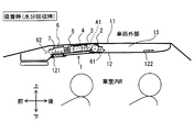
- the humidifier 101 of the second embodiment is different from the first embodiment in that air outside the vehicle is taken into the casing 6 instead of the air in the ceiling space 13 at the time of adsorption.
- the humidifier 101 includes a second opening 111 that communicates with the outside of the vehicle.
- the second opening 111 constitutes a passage that penetrates the casing 6 and the vehicle top plate 11.
- the second opening 111 is a suction inlet for suction that sucks air outside the vehicle into the casing 6 during suction.
- the second opening 111 is preferably provided with a filter that collects dust, dust and the like carried together with air.
- air outside the vehicle introduced from the second opening 111 is cooled by the cooling device 5, passes through the adsorbent module 4, releases moisture to the adsorbent, and is further heated by the heating device 3. After that, the air is blown out from the first opening 61 to the space 13 in the ceiling.
- the flow of air at the time of adsorption is indicated by broken-line arrows in FIG.
- the 2nd opening part 111 is provided in the place which opposes an up-down direction with respect to the blower outlet part 121. As shown in FIG. The second opening 111 and the outlet 121 are switched between an open state and a closed state by the switching door 207.
- the switching door 207 is a switching member, and is controlled by the control device so as to close the second opening 111 and open the outlet 121 when desorbing, and close the outlet 121 and open the second opening 111 during adsorption. Is done. Therefore, the switching door 207 is located in front of the cooling device 5 in the casing 6 and provided at the front end of the casing 6.
- the blower 2 takes in air outside the vehicle at the time of adsorption, blows the air to the adsorbent module 4, and adsorbs moisture in the air with the adsorbent.
- moisture contained in the air outside the vehicle is adsorbed by the adsorbent, so that moisture is removed from the air having less influence on heating than the air in the vehicle interior R whose relative humidity has been lowered by heating. Can be recovered.
- the humidification apparatus 101 which can aim at suppression of the humidification capability fall by vehicle interior heating can be provided.
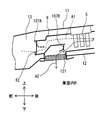
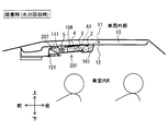
- the third embodiment is different from the first embodiment in that the ceiling interior member 12 includes a communication opening 122 that allows the space 13 in the ceiling and the vehicle interior R to communicate with each other.
- the communication opening 122 opens toward the lower vehicle interior R so as to penetrate the ceiling interior member 12, and constitutes a passage that connects the ceiling interior space 13 and the vehicle interior R.
- the communication opening 122 is provided, for example, so as to open above an occupant seated in a rear seat of the vehicle interior R.
- the communication opening 122 is preferably provided with a filter that collects dust, dust and the like carried together with air.
- the communication opening 122 is provided at a position closer to the first opening 61 that is the suction outlet (desorption inlet) than the second opening 62 that is the suction inlet.
- the distance L1 between the communication opening 122 and the first opening 61 is shorter than the distance L2 between the communication opening 122 and the second opening 62. That is, the first opening 61 is located between the second opening 62 and the communication opening 122 in the front-rear direction.
- the communication opening 122 communicates the ceiling interior space 13 and the vehicle interior R at a position closer to the rear seat than the front seat. Accordingly, the communication opening 122 is located on the side opposite to the side where the casing 6 is installed in the ceiling interior space 13.
- the air introduced into the ceiling space 13 from the first opening 61 is heated by the heating device 3 and then moisture is added by the adsorbent module 4. Further, after being cooled by the cooling device 5, the air is blown out from the air outlet portion 121 to the vehicle interior R. At this time, the air in the ceiling interior space 13 flows in the direction A2 indicated by the solid line arrow in FIG. As a result, the air in the vehicle interior R is drawn into the ceiling interior space 13 through the communication opening 122. That is, the same amount of air in the vehicle interior R as the humidified air supplied to the vehicle interior R through the air outlet portion 121 during humidification is sucked into the ceiling interior space 13 through the communication opening 122.
- the air in the ceiling space 13 is sucked into the casing 6 and is blown out to the ceiling space 13 after the moisture is collected. Therefore, the ceiling space 13 does not become negative pressure with respect to the vehicle interior R. . Thereby, the air in the vehicle interior R is not drawn into the ceiling interior space 13 through the communication opening 122.
- the communication opening 122 that allows the ceiling space 13 and the vehicle interior R to communicate with each other is provided in a position closer to the desorption suction port than the suction suction port. Air can be actively taken into the ceiling space 13 from the communication opening 122. According to this, the air approach path from the vehicle interior R to the ceiling interior space 13 can be limited, which contributes to the stable temperature and humidity of the ceiling interior space 13 around the humidifier 1.
- the communication opening 122 is located on the opposite side to the side where the casing 6 is installed in the ceiling interior space 13, so that the air entry path from the vehicle interior R to the ceiling interior space 13 is away from the humidifier 1. Can be set to According to this, the temperature and humidity state of the space 13 in the ceiling around the humidifier 1 can be further stabilized.
- the humidifier of the fourth embodiment includes a cylindrical member 123 that is provided on the side of the space 13 in the ceiling of the communication opening 122 and has a gap with the vehicle top plate 11.
- the tubular member 123 extends from the communication opening 122 toward the vehicle top plate 11, and a gap is formed between the tubular member 123 and the vehicle top plate 11.
- a wind direction guide member 123a is provided in the ceiling space 13 located on the downstream side of the communication opening 122. The wind direction guide member 123a is opposed to the vehicle top plate 11 on the vehicle top plate 11 side of the tubular member 123 and extends to the casing 6 side.
- the wind direction guide member 123 a extends from the end of the tubular member 123 on the vehicle top plate 11 side toward the casing 6.
- the wind direction guiding member 123a has a function of guiding the air in the vehicle interior R taken into the ceiling interior space 13 through the communication opening 122 when detached, along the vehicle top plate 11.
- the wind direction guide member 123 a is a plate-like member that extends along the inner surface of the vehicle top plate 11.
- the air direction guide member 123a causes the air flowing in from the communication opening 122 and rising in the ceiling space 13 to flow along the vehicle top plate 11 in the direction toward the first opening 61, as indicated by solid arrows in FIG. To guide.
- the air in the vehicle interior R can flow down toward the first opening 61 along the vehicle top plate 11. Since the vehicle top plate 11 is cooler than the heated and air-conditioned vehicle interior R, the air in the vehicle interior R can be efficiently cooled, and the moisture recovery efficiency of the humidifier can be further improved.
- the humidifying device 201 of the fifth embodiment is not installed in the ceiling interior space 13 but is installed on the lower surface of the ceiling interior member 12 that forms the ceiling interior space 13 above the passenger. Is different.
- the humidifier 201 includes a second opening 111 that communicates with the ceiling space 13.
- the second opening 111 constitutes a passage that penetrates the casing 106 and the ceiling interior member 12.
- the second opening 111 is a suction inlet for suction that sucks air in the ceiling space 13 into the casing 6 during suction.
- the second opening 111 is preferably provided with a filter that collects dust, dust, and the like.
- a first opening 161 provided in the casing 106 in the vicinity of the blower 2 constitutes a passage that penetrates the casing 106 and the ceiling interior member 12, and discharges the air after the moisture collection to the ceiling interior space 13. This is the exit.
- the air introduced into the ceiling space 13 from the second opening 111 is cooled by the cooling device 5 and then passes through the adsorbent module 4 to release moisture to the adsorbent. After being heated, the air is blown out from the first opening 161 to the ceiling space 13.
- the flow of air at the time of adsorption is indicated by broken-line arrows in FIG.
- the blower 2, the heating device 3, the adsorbent module 4, the cooling device 5 and the like are arranged at intervals.
- at least two of the blower 2, the heating device 3, the adsorbent module 4, and the cooling device 5 may be integrated and have a plurality of functions.
- the arrangement of the heating device 3, the adsorbent module 4, and the cooling device 5 inside the humidifying device 1 is not limited to the form described in the above-described embodiment. A configuration in which these devices are arranged separately in an air passage that is lined up and down in two stages may be employed. Further, the humidifying device 1 may be configured such that an air passage at the time of adsorption and an air passage at the time of desorption are arranged in two stages vertically, and each device is installed at a predetermined position of each passage.
- the adsorbent module 4 is configured by stacking and arranging a plurality of metal plate-like members carrying the adsorbent at intervals.
- an adsorbent may be supported on a corrugated plate bent in a wave shape, and the corrugated plates may be stacked and arranged at intervals.
- the adsorbent may be supported on a honeycomb member having a passage formed in a hexagonal cross section.
- the blower may have a wind direction changing function that can change the wind direction guided by the guide member to a direction opposite to the direction A1 and the direction A2 by a guide member whose rotational position changes.
- the air outlet portion 121 is located on the front seat side and the communication opening portion 122 is located on the rear seat side so that the humidified air is supplied to the front seat side of the vehicle.
- the positional relationship between the air outlet 121 and the communication opening 122 is not limited to this example.
- the air outlet portion 121 is arranged to open toward the upper body side of the occupant seated in the front seat, but the position of the air outlet portion is not limited to this example.
- the communication opening 122 of the third embodiment can also be applied to the humidifying device 101 of the second embodiment. Moreover, the communication opening part 122 of 3rd Embodiment is applicable also to the humidification apparatus 201 of 5th Embodiment.
Landscapes
- Engineering & Computer Science (AREA)
- Mechanical Engineering (AREA)
- Air-Conditioning For Vehicles (AREA)
- Central Air Conditioning (AREA)
- Air Conditioning Control Device (AREA)
- Air Humidification (AREA)
Priority Applications (3)
| Application Number | Priority Date | Filing Date | Title |
|---|---|---|---|
| DE112016003388.5T DE112016003388T5 (de) | 2015-07-29 | 2016-07-12 | Befeuchtungseinrichtung |
| US15/740,171 US10675951B2 (en) | 2015-07-29 | 2016-07-12 | Humidifying device |
| CN201680043794.7A CN107848377B (zh) | 2015-07-29 | 2016-07-12 | 加湿装置 |
Applications Claiming Priority (2)
| Application Number | Priority Date | Filing Date | Title |
|---|---|---|---|
| JP2015150011A JP6304164B2 (ja) | 2015-07-29 | 2015-07-29 | 加湿装置 |
| JP2015-150011 | 2015-07-29 |
Publications (1)
| Publication Number | Publication Date |
|---|---|
| WO2017018191A1 true WO2017018191A1 (ja) | 2017-02-02 |
Family
ID=57885238
Family Applications (1)
| Application Number | Title | Priority Date | Filing Date |
|---|---|---|---|
| PCT/JP2016/070485 WO2017018191A1 (ja) | 2015-07-29 | 2016-07-12 | 加湿装置 |
Country Status (5)
| Country | Link |
|---|---|
| US (1) | US10675951B2 (de) |
| JP (1) | JP6304164B2 (de) |
| CN (1) | CN107848377B (de) |
| DE (1) | DE112016003388T5 (de) |
| WO (1) | WO2017018191A1 (de) |
Families Citing this family (1)
| Publication number | Priority date | Publication date | Assignee | Title |
|---|---|---|---|---|
| JP2022021029A (ja) * | 2020-07-21 | 2022-02-02 | 株式会社東芝 | 湿度調整フィルター、及び磁気記録再生装置 |
Citations (4)
| Publication number | Priority date | Publication date | Assignee | Title |
|---|---|---|---|---|
| JPH06143997A (ja) * | 1992-11-04 | 1994-05-24 | Matsushita Electric Ind Co Ltd | 車両用加湿装置 |
| JP2009280148A (ja) * | 2008-05-23 | 2009-12-03 | Denso Corp | 車両用除加湿装置及びその装置の運転方法 |
| WO2014162644A1 (ja) * | 2013-04-05 | 2014-10-09 | 株式会社デンソー | 加湿装置 |
| JP2015101234A (ja) * | 2013-11-26 | 2015-06-04 | 株式会社前川製作所 | 車両用空調装置 |
Family Cites Families (14)
| Publication number | Priority date | Publication date | Assignee | Title |
|---|---|---|---|---|
| US5873256A (en) * | 1994-07-07 | 1999-02-23 | Denniston; James G. T. | Desiccant based humidification/dehumidification system |
| US5509275A (en) * | 1994-09-22 | 1996-04-23 | General Motors Corporation | Dehumidifying mechanism for auto air conditioner |
| US6029462A (en) * | 1997-09-09 | 2000-02-29 | Denniston; James G. T. | Desiccant air conditioning for a motorized vehicle |
| US5878590A (en) * | 1998-02-25 | 1999-03-09 | General Motors Corporation | Dehumidifying mechanism for auto air conditioner with improved space utilization and thermal efficiency |
| JP2005112297A (ja) * | 2003-10-10 | 2005-04-28 | Denso Corp | 車両用空調装置 |
| JP5055944B2 (ja) * | 2006-10-18 | 2012-10-24 | トヨタ自動車株式会社 | 車両用除加湿装置 |
| JP5266657B2 (ja) * | 2007-03-30 | 2013-08-21 | 三菱樹脂株式会社 | 車両用除加湿装置 |
| JP4720772B2 (ja) * | 2007-04-06 | 2011-07-13 | トヨタ自動車株式会社 | 車両用除加湿装置 |
| JP2008254638A (ja) | 2007-04-06 | 2008-10-23 | Toyota Motor Corp | 車両用加湿装置 |
| US20090277195A1 (en) * | 2008-05-09 | 2009-11-12 | Thermo King Corporation | Refrigeration system including a desiccant |
| JP5239717B2 (ja) * | 2008-10-06 | 2013-07-17 | 株式会社デンソー | 除加湿装置 |
| DE102009028931A1 (de) * | 2009-08-27 | 2011-03-03 | BSH Bosch und Siemens Hausgeräte GmbH | Verfahren zum Betreiben eines Adsorptions-Trockners und Trockner zur Realisierung des Verfahrens |
| DE102013112825A1 (de) * | 2013-11-20 | 2015-05-21 | Valeo Klimasysteme Gmbh | Frontmodul eines Fahrzeugs |
| JP6394521B2 (ja) | 2014-08-21 | 2018-09-26 | 株式会社デンソー | 加湿装置 |
-
2015
- 2015-07-29 JP JP2015150011A patent/JP6304164B2/ja not_active Expired - Fee Related
-
2016
- 2016-07-12 WO PCT/JP2016/070485 patent/WO2017018191A1/ja active Application Filing
- 2016-07-12 US US15/740,171 patent/US10675951B2/en active Active
- 2016-07-12 DE DE112016003388.5T patent/DE112016003388T5/de not_active Withdrawn
- 2016-07-12 CN CN201680043794.7A patent/CN107848377B/zh not_active Expired - Fee Related
Patent Citations (4)
| Publication number | Priority date | Publication date | Assignee | Title |
|---|---|---|---|---|
| JPH06143997A (ja) * | 1992-11-04 | 1994-05-24 | Matsushita Electric Ind Co Ltd | 車両用加湿装置 |
| JP2009280148A (ja) * | 2008-05-23 | 2009-12-03 | Denso Corp | 車両用除加湿装置及びその装置の運転方法 |
| WO2014162644A1 (ja) * | 2013-04-05 | 2014-10-09 | 株式会社デンソー | 加湿装置 |
| JP2015101234A (ja) * | 2013-11-26 | 2015-06-04 | 株式会社前川製作所 | 車両用空調装置 |
Also Published As
| Publication number | Publication date |
|---|---|
| CN107848377B (zh) | 2020-07-07 |
| CN107848377A (zh) | 2018-03-27 |
| US10675951B2 (en) | 2020-06-09 |
| DE112016003388T5 (de) | 2018-04-05 |
| JP6304164B2 (ja) | 2018-04-04 |
| US20180312043A1 (en) | 2018-11-01 |
| JP2017030409A (ja) | 2017-02-09 |
Similar Documents
| Publication | Publication Date | Title |
|---|---|---|
| EP2143574B1 (de) | Entfeuchtungs/befeuchtungsvorrichtung für ein fahrzeug | |
| JP6394521B2 (ja) | 加湿装置 | |
| WO2014065255A1 (ja) | バッテリ温度調整ユニット及びこれを搭載した車両 | |
| WO2014162644A1 (ja) | 加湿装置 | |
| JP4539343B2 (ja) | 空気調和装置 | |
| JP2000108655A (ja) | 除湿装置 | |
| JP2008254618A (ja) | 車両用除加湿装置 | |
| JP2000146220A (ja) | 空気調和手段及び空気調和装置 | |
| JP2009274587A (ja) | 車両用除加湿装置 | |
| JP4538846B2 (ja) | 空気調和装置 | |
| JP6413680B2 (ja) | 加湿装置 | |
| JP5089254B2 (ja) | 自動車用調湿空調システム | |
| CN111907287A (zh) | 车辆用空调系统及其二氧化碳收集模块 | |
| JP6831167B2 (ja) | 電動車両 | |
| JP2009262580A (ja) | 車両用除加湿装置 | |
| WO2017018191A1 (ja) | 加湿装置 | |
| JP5083035B2 (ja) | 車両用除加湿装置及びその装置の運転方法 | |
| JP2013035484A (ja) | 車両用空調装置 | |
| JP6350483B2 (ja) | 加湿装置 | |
| JP2009280149A (ja) | 車両用除加湿装置 | |
| JP2006143042A (ja) | 車両用空調装置 | |
| JP2018118630A (ja) | 加湿装置 | |
| WO2017130547A1 (ja) | 加湿装置 | |
| JP2005254954A (ja) | 車両空調装置 | |
| CN113276638A (zh) | 车辆用净化装置 |
Legal Events
| Date | Code | Title | Description |
|---|---|---|---|
| 121 | Ep: the epo has been informed by wipo that ep was designated in this application |
Ref document number: 16830296 Country of ref document: EP Kind code of ref document: A1 |
|
| WWE | Wipo information: entry into national phase |
Ref document number: 15740171 Country of ref document: US |
|
| WWE | Wipo information: entry into national phase |
Ref document number: 112016003388 Country of ref document: DE |
|
| 122 | Ep: pct application non-entry in european phase |
Ref document number: 16830296 Country of ref document: EP Kind code of ref document: A1 |