WO2017017831A1 - パンツ型の吸収性物品、及びその製造方法 - Google Patents
パンツ型の吸収性物品、及びその製造方法 Download PDFInfo
- Publication number
- WO2017017831A1 WO2017017831A1 PCT/JP2015/071603 JP2015071603W WO2017017831A1 WO 2017017831 A1 WO2017017831 A1 WO 2017017831A1 JP 2015071603 W JP2015071603 W JP 2015071603W WO 2017017831 A1 WO2017017831 A1 WO 2017017831A1
- Authority
- WO
- WIPO (PCT)
- Prior art keywords
- absorbent article
- portions
- folded
- type absorbent
- longitudinal direction
- Prior art date
- Legal status (The legal status is an assumption and is not a legal conclusion. Google has not performed a legal analysis and makes no representation as to the accuracy of the status listed.)
- Ceased
Links
Images





Classifications
-
- A—HUMAN NECESSITIES
- A61—MEDICAL OR VETERINARY SCIENCE; HYGIENE
- A61F—FILTERS IMPLANTABLE INTO BLOOD VESSELS; PROSTHESES; DEVICES PROVIDING PATENCY TO, OR PREVENTING COLLAPSING OF, TUBULAR STRUCTURES OF THE BODY, e.g. STENTS; ORTHOPAEDIC, NURSING OR CONTRACEPTIVE DEVICES; FOMENTATION; TREATMENT OR PROTECTION OF EYES OR EARS; BANDAGES, DRESSINGS OR ABSORBENT PADS; FIRST-AID KITS
- A61F13/00—Bandages or dressings; Absorbent pads
- A61F13/15—Absorbent pads, e.g. sanitary towels, swabs or tampons for external or internal application to the body; Supporting or fastening means therefor; Tampon applicators
-
- A—HUMAN NECESSITIES
- A61—MEDICAL OR VETERINARY SCIENCE; HYGIENE
- A61F—FILTERS IMPLANTABLE INTO BLOOD VESSELS; PROSTHESES; DEVICES PROVIDING PATENCY TO, OR PREVENTING COLLAPSING OF, TUBULAR STRUCTURES OF THE BODY, e.g. STENTS; ORTHOPAEDIC, NURSING OR CONTRACEPTIVE DEVICES; FOMENTATION; TREATMENT OR PROTECTION OF EYES OR EARS; BANDAGES, DRESSINGS OR ABSORBENT PADS; FIRST-AID KITS
- A61F13/00—Bandages or dressings; Absorbent pads
- A61F13/15—Absorbent pads, e.g. sanitary towels, swabs or tampons for external or internal application to the body; Supporting or fastening means therefor; Tampon applicators
- A61F13/45—Absorbent pads, e.g. sanitary towels, swabs or tampons for external or internal application to the body; Supporting or fastening means therefor; Tampon applicators characterised by the shape
- A61F13/49—Absorbent pads, e.g. sanitary towels, swabs or tampons for external or internal application to the body; Supporting or fastening means therefor; Tampon applicators characterised by the shape specially adapted to be worn around the waist, e.g. diapers, nappies
-
- A—HUMAN NECESSITIES
- A61—MEDICAL OR VETERINARY SCIENCE; HYGIENE
- A61F—FILTERS IMPLANTABLE INTO BLOOD VESSELS; PROSTHESES; DEVICES PROVIDING PATENCY TO, OR PREVENTING COLLAPSING OF, TUBULAR STRUCTURES OF THE BODY, e.g. STENTS; ORTHOPAEDIC, NURSING OR CONTRACEPTIVE DEVICES; FOMENTATION; TREATMENT OR PROTECTION OF EYES OR EARS; BANDAGES, DRESSINGS OR ABSORBENT PADS; FIRST-AID KITS
- A61F13/00—Bandages or dressings; Absorbent pads
- A61F13/15—Absorbent pads, e.g. sanitary towels, swabs or tampons for external or internal application to the body; Supporting or fastening means therefor; Tampon applicators
- A61F13/45—Absorbent pads, e.g. sanitary towels, swabs or tampons for external or internal application to the body; Supporting or fastening means therefor; Tampon applicators characterised by the shape
- A61F13/49—Absorbent pads, e.g. sanitary towels, swabs or tampons for external or internal application to the body; Supporting or fastening means therefor; Tampon applicators characterised by the shape specially adapted to be worn around the waist, e.g. diapers, nappies
- A61F13/496—Absorbent pads, e.g. sanitary towels, swabs or tampons for external or internal application to the body; Supporting or fastening means therefor; Tampon applicators characterised by the shape specially adapted to be worn around the waist, e.g. diapers, nappies in the form of pants or briefs
Definitions
- the present invention relates to a pants-type absorbent article that absorbs excrement such as urine and a method for producing the same.
- pants-type disposable diapers are used as absorbent articles that absorb excrement such as urine.
- This diaper is unfolded from the abdominal side that is placed on the wearer's ventral side when worn, the back side that is placed on the back of the wearer, and the crotch that is placed between the wearer's crotch Have in. And, in such a state that the unfolded diaper is folded in two at the crotch portion and the abdomen and the dorsal side are overlapped, the abdomen and the dorsal side are each end in the lateral direction of the diaper. By being fused at portions corresponding to the portions, a waist opening and a pair of leg openings are formed, whereby the diaper is put into a pants-type state. The diaper is provided to the user in such a pants-type state.
- Patent Document 1 discloses an example of this pant-type diaper.
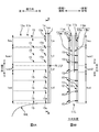
- FIG. 1A is a schematic enlarged view of a lateral end 1e 'of the diaper 1'
- FIG. 1B is a schematic view taken along the line BB in FIG. 1A.
- the above-described ventral side portion 11a ′ and back side portion 11b ′ are portions 11aew ′ corresponding to the respective end portions 1e ′ in the lateral direction of the diaper 1 ′.
- 11be ′ and bonded to each other, thereby forming a fused portion j ′ at the edge 1ee ′ of each end 1e ′ (see the dot pattern portion in FIG. 1A). .
- the fusion part j ' is formed by irradiating a laser beam to melt the abdominal part 11a' and the back part 11b 'at the edge part 1ee'.
- the fusion part j ′ extends linearly along the edge 1ee ′ from the waistline opening 1HB ′ to the leg opening 1HL ′. Further, when the diaper 1 ′ is removed from the wearer after excretion, the abdomen portion 11 a ′ and the dorsal side portion 11 b ′ are peeled off and separated at the fused portion j ′.
- the total value of the number of stacked sheets forming the ventral side portion 11a ′ and the back side portion 11b ′ is 8 at each of the lateral end portions 1e ′.
- a diaper 1 ′ having a sheet portion and four portions arranged in the vertical direction is disclosed. That is, the abdomen portion 11a ′ and the back portion 11b ′ are both sheet members in which two sheets are laminated, and the sheet member is folded at the upper end portion that forms the waistline opening 1HB ′.
- the upper half 1eu ′ of the end portion 1e ′ is a portion where the number of stacked sheets is eight, and the lower half 1ed ′ below the portion is a portion where the number of stacked sheets is four. ing.
- the fusion part j ′ is formed by melting the abdominal part 11a ′ and the back part 11b ′, so that the fusion part j8 ′ formed in the eight parts is fused.
- the adhesion strength is generally excessively greater than the fusion strength of the fusion part j4 ′ formed in the four portions.
- the ventral part 11a ′ and the dorsal part 11b ′ are peeled off at the fusion part j ′ so as to replace the diaper 1 ′, the eight parts and the four parts shown in FIG. Since the fusion strength suddenly changes at the boundary position BL ′, the force applied to peel off along the fusion part j ′ at the boundary position BL ′ or the like is a force directed inward in the lateral direction. As a result, there is a risk of tearing the abdominal part 11a 'or the dorsal part 11b' inward in the lateral direction. In other words, there is a risk of tearing. Then, the abdominal side part 11a 'or the back side part 11b' of the diaper 1 'may be greatly damaged, and as a result, a large amount of excrement may be leaked when changing the diaper.
- lateral tearing is liable to occur when the form of the fused part j 'is a linear form along the edge 1ee'. That is, in general, a line along the edge 1ee ′ as described above is compared with a fused portion (not shown) in a form fused with an appropriate fusion pattern such as heat seal or ultrasonic seal.
- the lateral dimension Ljw ′ of the fused portion j ′ is very small, for example, 0.5 mm to 3 mm.
- the present invention has been made in view of the conventional problems as described above, and the purpose thereof is a lateral that can occur when the abdomen and the dorsal side are peeled off at a linearly fused portion. It is in suppressing tearing.
- the main invention for achieving the above object is: An absorbent article having an abdominal side portion disposed on the wearer's ventral side when worn, a back side portion disposed on the wearer's back side, and a crotch portion disposed between the wearer's crotch In addition, the abdomen and the dorsal part are folded in half at the crotch and the abdomen and the dorsal part overlap each other in the lateral direction of the absorbent article.
- a pants-type absorbent article in which a waist opening and a pair of leg openings are formed at positions different from each other in the longitudinal direction intersecting with the transverse direction.
- the number of stacked sheets forming the ventral portion and the dorsal portion is the first portion of the plurality of portions
- the second portion located next to the first portion in the vertical direction is different from the first portion by only one sheet
- a fusion portion formed by fusing the abdomen side portion and the back side portion continuously extends linearly along the edge portion at the edge portion along the longitudinal direction. It is a pants-type absorbent article characterized by existing.
- An absorbent article having an abdominal side portion disposed on the wearer's ventral side when worn, a back side portion disposed on the wearer's back side, and a crotch portion disposed between the wearer's crotch
- the abdomen and the dorsal part are folded in half at the crotch and the abdomen and the dorsal part overlap each other in the lateral direction of the absorbent article.
- a pants-type absorbent article in which a waistline opening and a pair of leghole openings are formed at positions different from each other in the longitudinal direction intersecting the transverse direction.
- a manufacturing method comprising: When the respective end portions of the pant-type absorbent article are divided into a plurality of portions in the longitudinal direction, the number of stacked sheets forming the ventral side portion and the back side portion is the plurality of portions.
- the first portion of the first portion and the second portion located next to the first portion in the vertical direction are different from each other by only one sheet, Conveying a continuous body in a state in which a plurality of parts that become the pants-type absorbent article in a state folded in two in the vertical direction are continuous in the horizontal direction, with the horizontal direction as a conveyance direction;
- the continuum is divided at the plurality of portions to form edges along the vertical direction in the plurality of portions, A linear fused portion that is formed by fusing the belly side portion and the back side portion of the portion that becomes the pant-type absorbent article and continuously extending along the edge portion to the edge portion.
- FIG. 1A is a schematic enlarged view of a lateral end 1e 'of a pant-type diaper 1'
- FIG. 1B is a schematic view taken along the line BB in FIG. 1A
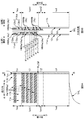
- FIG. 5B is a schematic enlarged view of a lateral end 1e of the diaper 1, and FIG.
- FIG. 5B is a schematic view taken along line BB in FIG. 5A.
- 6A is a schematic enlarged view of a lateral end 1e of the diaper 1 for explaining the arrangement positions of the thread-like elastic members 15, 15...
- FIG. 6B is a schematic view taken along the line BB in FIG.
- FIG. 7A is a schematic enlarged view of a lateral end 1e of the diaper 1 for explaining another arrangement example of the thread-like elastic members 15, 15...
- FIG. 7B is a view taken along the line BB in FIG. FIG. It is explanatory drawing of the arrangement position of crimping
- FIG. 9A shows an application pattern of hot-melt adhesives HMAa and HMAb for fixing the portions 11at and 11bt folded at the ventral part 11a and the dorsal part 11b to the skin side surfaces of the ventral part 11a and the dorsal part 11b, respectively.
- FIG. 9 is a schematic enlarged view of a lateral end 1e of the diaper 1
- FIG. 9B is a schematic view taken along the line BB in FIG. 9A. It is a schematic perspective view of the manufacturing apparatus 30 used for manufacture of the diaper 1.
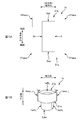
- FIG. 12A is a schematic plan view of a three-piece type diaper 1 in an unfolded state as an example of another embodiment as viewed from the skin side
- FIG. 12B is a schematic perspective view of the diaper 1 in a pants shape. It is.
- An absorbent article having an abdominal side portion disposed on the wearer's ventral side when worn, a back side portion disposed on the wearer's back side, and a crotch portion disposed between the wearer's crotch
- the abdomen and the dorsal part are folded in half at the crotch and the abdomen and the dorsal part overlap each other in the lateral direction of the absorbent article.
- a pants-type absorbent article in which a waist opening and a pair of leg openings are formed at positions different from each other in the longitudinal direction intersecting with the transverse direction.
- the number of stacked sheets forming the ventral portion and the dorsal portion is the first portion of the plurality of portions
- the second portion located next to the first portion in the vertical direction is different from the first portion by only one sheet
- a fusion portion formed by fusing the abdomen side portion and the back side portion continuously extends linearly along the edge portion at the edge portion along the longitudinal direction. It is a pants-type absorbent article characterized by existing.
- the plurality of portions related to the end portion include a first portion and a second portion that are adjacent in the vertical direction, and the first portion and the second portion Are different from each other in only one sheet. Accordingly, it is possible to suppress a rapid change in the fusion strength at the boundary position between the fusion portion of the first portion and the fusion portion of the second portion.
- the ventral portion and the dorsal side portion are peeled off at the fusion portion, the ventral portion can be smoothly and smoothly located at the boundary position of the fusion portion between the first portion and the second portion.
- the back side portion can be peeled off, and as a result, lateral tearing can be suppressed.
- Such a pants-type absorbent article The first portion is located on the waistline opening side in the longitudinal direction than the second portion, The plurality of portions has a third portion adjacent to the leg opening portion side in the longitudinal direction of the second portion, The second part and the third part are preferably different from each other in the number of stacked layers.
- the number of stacked third portions adjacent to the second portion is also different from the number of stacked second portions by only one. Therefore, it is possible to suppress a rapid change in the fusion strength at the boundary position between the fusion part of the second part and the fusion part of the third part, and as a result, in the fusion part, It is possible to more reliably suppress lateral tearing that may occur when peeling the film.
- Each of the end portions has at least three portions as the plurality of portions, It is desirable that the number of the stacked portions of the plurality of portions is gradually reduced from the trunk opening to the leg opening along the vertical direction.
- the number of stacked layers of the plurality of portions related to the end portion is gradually reduced along the vertical direction. Therefore, a rapid change in the fusion strength of the fusion part is suppressed over substantially the entire length in the vertical direction. And thereby, it becomes possible to more reliably suppress lateral tearing that may occur when the abdomen and the dorsal side are peeled off at the fusion part.
- Each of the end portions has at least four portions as the plurality of portions,
- the plurality of portions preferably differ from each other in the lengthwise direction by the number of stacked layers by one.
- the plurality of portions related to the end portion have at least four portions, and the plurality of portions are each a portion adjacent to the longitudinal direction. There is only one difference in the number of layers. Therefore, a rapid change in the fusion strength of the fusion part is suppressed over substantially the entire length in the vertical direction. And thereby, it becomes possible to more reliably suppress lateral tearing that may occur when the abdomen and the dorsal side are peeled off at the fusion part.
- the ventral portion and the dorsal side portion each have a plurality of thread-like elastic members along the transverse direction in the longitudinal direction,
- the second portion is positioned closer to the leg opening in the vertical direction than the first portion, and the number of stacked layers of the second portion is the number of stacked layers of the first portion. Less than It is desirable that the thread-like elastic member does not exist at least in the fusion part of the second portion.
- the above-described thread-like elastic member is not present at least in the fusion part of the second portion. Therefore, it is possible to quickly avoid a situation in which the fusion strength of the fusion part of the second portion is lowered due to the presence of the thread-like elastic member. As a result, it is possible to suppress further reduction in the fusion strength of the fusion part of the second part, which is already lower than the fusion part of the first part based on the fact that the number of laminated sheets is one less. Thus, it is possible to suppress further divergence of the fusion strength between the fusion part of the first part and the fusion part of the second part. Therefore, it is possible to effectively suppress a sudden change in the fusion strength between the fusion part of the first part and the fusion part of the second part.
- the thread-like elastic member is not disposed in a part having the same vertical position as the second part.
- the thread-like elastic member is disposed in the same position in the longitudinal direction and the second portion in the ventral side portion and the dorsal side portion, and the lateral end of the thread-like elastic member is It is desirable that the second portion is located on the inner side in the lateral direction than the fusion portion.
- Such a pants-type absorbent article The second portion is positioned closer to the leg opening in the vertical direction than the first portion, and the number of stacked layers of the second portion is the number of stacked layers of the first portion. Less than The ventral part and the dorsal part are formed by laminating a plurality of sheets in the thickness direction, A plurality of crimping portions for crimping the plurality of sheets are formed discontinuously in the longitudinal direction and the lateral direction while being dented in the thickness direction, It is desirable that the crimping part is not present at least in the fusion part of the second part.
- the above-mentioned crimping part is not present at least in the fusion part of the second part. Therefore, it is possible to quickly avoid a situation in which a space is formed in the fusion portion of the second portion due to the presence of the crimp portion and the fusion strength is reduced. As a result, it is possible to suppress further reduction in the fusion strength of the fusion part of the second part, which is already lower than the fusion part of the first part based on the fact that the number of laminated sheets is one less. Thus, it is possible to suppress further divergence of the fusion strength between the fusion part of the first part and the fusion part of the second part. Therefore, it is possible to effectively suppress a sudden change in the fusion strength between the fusion part of the first part and the fusion part of the second part.
- Such a pants-type absorbent article The sheet forming the abdomen side portion is folded back in the longitudinal direction to form a bent portion at the position of the waistline opening, and the folded portion is overlapped on the sheet from the skin side with an adhesive. Fixed to the seat The sheet forming the back side portion is folded back in the longitudinal direction to form a folded portion at the position of the waistline opening, and the folded portion is overlapped on the sheet from the skin side while being overlapped.
- the second portion is formed, and the first portion is formed adjacent to the longitudinal opening of the second portion in the longitudinal direction,
- the application area of the adhesive in the folded portion relating to the abdomen and the application area located in the first portion, and the application of the adhesive in the folded portion relating to the back side It is desirable that the coating region located in the first portion overlaps with respect to the vertical direction.
- the folded-up portion of the adhesive on the abdomen side is an application region of the adhesive, which is located on the first portion, and the folded-up portion on the back side.
- the application region of the adhesive in the part and the application region located in the first part overlap with each other in the vertical direction. Therefore, when the ventral part and the dorsal part are peeled off at the fusion part starting from the waistline opening, the folded part relating to the ventral part is brought to the dorsal part, or Conversely, it is possible to prevent a situation in which the folded portion relating to the dorsal side is brought to the ventral side.
- Such a pants-type absorbent article The sheet forming the abdomen side portion is folded back in the longitudinal direction to form a bent portion at the position of the waistline opening, and the folded portion is overlapped on the sheet from the skin side with an adhesive. Fixed to the seat The sheet forming the back side portion is folded back in the longitudinal direction to form a folded portion at the position of the waistline opening, and the folded portion is overlapped on the sheet from the skin side while being overlapped. Fixed to the seat By projecting the folded portion of the back side portion toward the leg opening in the vertical direction rather than the folded portion of the ventral side portion, the second portion is It is preferable that the first portion is formed adjacent to the longitudinal opening side of the waist portion of the second portion.
- the folded portion of the back side portion is more in the direction of the leg opening along the vertical direction than the folded portion of the ventral portion. Protruding. Therefore, it is possible to suppress the lateral tearing of the dorsal part over the lateral tearing of the ventral part, and as a result, stools such as soft stools leak due to lateral tearing of the dorsal part when replacing the absorbent article Can be prevented.
- An absorbent article having an abdominal side portion disposed on the wearer's ventral side when worn, a back side portion disposed on the wearer's back side, and a crotch portion disposed between the wearer's crotch
- the abdomen and the dorsal part are folded in half at the crotch and the abdomen and the dorsal part overlap each other in the lateral direction of the absorbent article.
- a pants-type absorbent article in which a waistline opening and a pair of leghole openings are formed at positions different from each other in the longitudinal direction intersecting the transverse direction.
- a manufacturing method comprising: When the respective end portions of the pant-type absorbent article are divided into a plurality of portions in the longitudinal direction, the number of stacked sheets forming the ventral side portion and the back side portion is the plurality of portions.
- the first portion of the first portion and the second portion located next to the first portion in the vertical direction are different from each other by only one sheet, Conveying a continuous body in a state in which a plurality of parts that become the pants-type absorbent article in a state folded in two in the vertical direction are continuous in the horizontal direction, with the horizontal direction as a conveyance direction;
- the continuum is divided at the plurality of portions to form edges along the vertical direction in the plurality of portions, A linear fused portion that is formed by fusing the belly side portion and the back side portion of the portion that becomes the pant-type absorbent article and continuously extending along the edge portion to the edge portion.
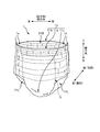
- FIG. 2 is a schematic perspective view of a pant-type disposable diaper 1 as an example of the pant-type absorbent article of the present embodiment.
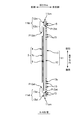
- 3A is a schematic plan view of the unfolded diaper 1 as viewed from the skin side
- FIG. 3B is a schematic view taken along the line BB in FIG. 3A.
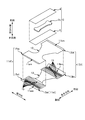
- FIG. 4 is an exploded perspective view schematically showing the unfolded diaper 1.
- the side that should be located on the skin side of the wearer is simply referred to as “skin side”, and on the other hand, on the non-skin side of the wearer.
- the side to be positioned is simply referred to as the “non-skin side”.
- this diaper 1 is a two-piece type diaper 1, for example. That is, the diaper 1 has an absorbent main body 3 that absorbs excrement such as urine, for example, in a substantially rectangular shape in plan view as a first part, and is provided so as to cover the non-skin side surface of the absorbent main body 3.
- the exterior sheet 11 having a substantially hourglass shape in plan view that forms the exterior of the diaper 1 is provided as the second component.
- the absorbent main body 3 has an absorbent core 2c that absorbs excreta.
- the absorbent core 2c is formed by molding liquid absorbent fibers such as pulp fibers and liquid absorbent granular materials such as superabsorbent polymers into a substantially hourglass shape in plan view as an example of a predetermined shape.
- the core 2c may be covered with a liquid-permeable covering sheet such as tissue paper as necessary.
- a liquid-permeable top sheet 4 such as a nonwoven fabric is provided on the skin side surface of the absorbent core 2c so as to cover the entire surface, and similarly, on the non-skin side surface of the absorbent core 2c.
- a liquid-impermeable leak-proof sheet 5 such as a film so as to cover the entire surface.
- both the sheets 4 and 5 are formed in a substantially rectangular shape in plan view, and both the sheets 4 and 5 are outside the outer contour of the absorbent core 2c over the entire circumference. It protrudes toward.
- the absorptive main body 3 of planar view substantially rectangular shape is formed.
- thread-like elastic members such as rubber thread may be provided along the longitudinal direction of the main body 3 at both ends in the width direction of the absorbent main body 3.
- Such a thread-like elastic member imparts stretchability to a portion of the absorbent main body 3 and the exterior sheet 11 in the vicinity of the leg opening 1HL. Therefore, the elastic member is fixed to both the sheets 4 and 5 by the hot melt adhesive in a state where the elastic member is extended from the natural length to a predetermined magnification while being interposed between the top sheet 4 and the leak-proof sheet 5.
- a leak-proof wall (not shown) may be provided in the absorbent main body 3 for the purpose of preventing side leakage of urine.
- a leak-proof wall portion is a well-known one called a three-dimensional gather, and is provided so as to stand on both end portions such as a skin side surface of the absorbent main body 3 by using a flexible sheet such as a nonwoven fabric, for example.
- 3A is a flexible sheet having a substantially hourglass shape in plan view, and the sheet 11 has a thickness direction, a longitudinal direction, and a width direction as three directions orthogonal to each other. ing. Moreover, the said exterior sheet
- seat 11 is divided into three parts 11a, 11b, and 11c regarding a longitudinal direction. That is, the exterior sheet 11 is provided on the abdomen side portion 11a disposed on the wearer's belly side, the back side portion 11b disposed on the wearer's back side, and the crotch portion 11c disposed on the wearer's crotch. It is divided.
- the crotch part 11c is located between the abdomen side part 11a and the dorsal side part 11b, so that the crotch part 11c has a portion 11c that is constricted in the width direction in a substantially hourglass shape in plan view. It has become.
- the outer sheet 11 is an inner layer sheet 12 that mainly forms the inner layer facing the wearer's skin when wearing the diaper 1, and an outer layer sheet 13 that mainly forms the outer layer facing the non-skin side when wearing the diaper,
- the inner layer sheet 12 and the outer layer sheet 13 are joined by pressure bonding while being overlapped in the thickness direction. Therefore, the exterior sheet 11 has a plurality of crimped portions eb, eb... (Which are not shown in FIGS. 2 to 4, refer to FIG. 8) in the longitudinal direction and the width direction. These are formed in an appropriate arrangement pattern such as a lattice pattern dispersed discontinuously.
- a non-woven fabric or a thermoplastic resin film containing thermoplastic resin fibers is used as the material of the inner layer sheet 12 and the outer layer sheet 13.
- a spunbond nonwoven fabric having a basis weight of 17 (g / m 2 ) is used as the material of the former inner layer sheet 12, while 5 (g / g) is used as the material of the latter outer layer sheet 13.
- an SMS nonwoven fabric spunbond / meltblown / spunbond nonwoven fabric having a basis weight of m 2
- the present invention is not limited to this.
- thread-like elastic members 15, 15... Such as thread rubber are inserted between the inner layer sheet 12 and the outer layer sheet 13.
- the thread-like elastic members 15, 15... Impart stretchability in the width direction to the abdomen side portion 11 a and the back side portion 11 b of the exterior sheet 11. Therefore, the thread-like elastic members 15, 15... Are fixed to the unfolded sheets 12, 13 by a hot melt adhesive while being arranged along the width direction in a state of being stretched from a natural length to a predetermined magnification. .
- a plurality of such thread-like elastic members 15, 15... are arranged in the longitudinal direction of the exterior sheet 11 while being spaced apart from each other, whereby the abdomen side portion 11 a and the back side portion 11 b are respectively described above. Stretchability is imparted over a wide range in the longitudinal direction.
- folded portions 11at and 11bt are provided on the end portion 11aeL of the abdomen side portion 11a and the end portion 11beL of the back side portion 11b, which are the respective end portions 11aeL and 11beL in the longitudinal direction of the exterior sheet 11.
- the exterior sheet 11 is folded inward in the longitudinal direction with a predetermined position in the longitudinal direction as a folding position at each of the end portion 11aeL of the ventral side portion 11a and the end portion 11beL of the back side portion 11b.
- the bent portions 11am and 11bm are formed at the bent position, and the folded portions 11at and 11bt are fixed with a hot melt adhesive while being superimposed on the skin side surface of the exterior sheet 11 from the skin side. .
- the longitudinal length L11at of the portion 11at folded at the end portion 11aeL of the abdominal side portion 11a is different from the longitudinal length L11bt of the portion 11bt folded at the end portion 11beL of the back side portion 11b.
- the latter length L11bt is longer than the former length L11at.
- the lengths of the folded portions 11at and 11bt in the longitudinal direction are different from each other between the inner layer sheet 12 and the outer layer sheet 13 forming the exterior sheet 11, and in this example, the length of the ventral portion 11a is different.
- the length L13at (L13bt) in the longitudinal direction of the folded portion 13at (13bt) of the outer layer sheet 13 is folded back at both the end portion 11aeL and the end portion 11beL of the back side portion 11b. It is longer than the length L12at (L12bt) in the longitudinal direction of the portion 12at (12bt).
- the front end position P13at (P13bt) in the longitudinal direction of the folded portion 13at (13bt) of the outer layer sheet 13 is the folded portion 12at (12bt) of the inner layer sheet 12.
- the absorptive main body 3 is fixed to the skin side surface of such an exterior sheet
- the abdomen part 11a and the dorsal part 11b are joined at the portions 11aew and 11bew corresponding to the respective end portions 1e in the width direction of the diaper 1, thereby forming a waistline opening 1HB and a pair of leghole openings 1HL and 1HL as shown in FIG. It is made into the form of the trousers type diaper 1.
- a direction parallel to the width direction of the exterior sheet 11 is referred to as a “lateral direction”.
- a direction parallel to the longitudinal direction of the exterior sheet 11 is referred to as a “longitudinal direction”.
- the horizontal direction and the vertical direction are orthogonal to each other.
- a direction perpendicular to both the horizontal direction and the vertical direction is referred to as a “front-rear direction”.
- the front in the front-rear direction is the abdomen side that is the front side of the wearer, and the rear side in the front-rear direction is the back side that is the rear side of the wearer.
- the vertical direction is the vertical direction, so the vertical direction is also referred to as the “vertical direction”.
- the leg opening 1HL is located below the waist opening 1HB.
- the lateral direction is also referred to as “left-right direction”.
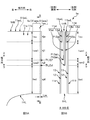
- FIG. 5A is a schematic enlarged view of a lateral end 1e of the diaper 1
- FIG. 5B is a schematic view taken along the line BB in FIG. 5A.
- the joining at the end 1e described above is performed by a fusion treatment by irradiation with a laser beam.
- the abdomen side portion 11a and the back side portion 11b of the exterior sheet 11 are fused at the portions 11aew and 11bew corresponding to the lateral end portion 1e of the diaper 1 by such fusion processing.
- each edge part 1ee along the vertical direction in each edge part 1e has each fusion part j continuously extended in the linear form along the said edge part 1ee. (See the dot pattern portion in FIG. 5A).
- the fusion part j has a dimension Ljw of, for example, 0.5 mm to 3 mm in the lateral direction, and the longitudinal direction of the edge 1ee that is a range from the position of the waistline opening 1HB to the position of the leghole opening 1HL. It extends over almost the entire length of.
- the lateral end 1 e is formed by laminating a plurality of inner layer sheets 12 and outer layer sheets 13 of the outer sheet 11.
- the end 1e has four portions 1eu, 1em1, 1em2, and 1ed (corresponding to a plurality of portions) that are different from each other in the vertical direction. ing. *
- the length L11at of the portions 11at and 11bt where the end portions 11aeL and 11beL of the abdominal side portion 11a as the end portions 11aeL and 11beL in the longitudinal direction of the exterior sheet 11 are folded back.
- L11bt are mutually folded in the vertical direction
- portions 12at and 13at (12bt, 13bt) are also folded in the vertical direction between the inner layer sheet 12 and the outer layer sheet 13 forming the exterior sheet 11.
- the lateral end 1e has an upper end portion 1eu (most on the waistline opening 1HB side) because the lengths L12at and L13at (L12bt, L13bt) are different from each other.
- the intermediate portion 1em1 has a 6-layer structure portion in which 6 sheets are stacked, and further, a 5-layer structure portion in which 5 sheets are stacked as a second intermediate portion 1em2 adjacent below the intermediate portion 1em1.
- a portion having a four-layer structure in which four sheets are laminated is provided as a lower end portion 1ed (a portion on the most leg opening 1HL side) adjacent to the lower portion.
- the upper end portion 1eu has a four-layer structure in which the inner layer sheet 12 and the outer layer sheet 13 are folded back with respect to the abdominal side portion 11a, and the inner layer sheet 12 also with respect to the back side portion 11b.
- the outer layer sheet 13 has a four-layer structure that is folded back, and the upper end portion 1eu has a total eight-layer structure.
- the folded portion 12at of the inner layer sheet 12 of the abdominal side portion 11a is eliminated, and the folded portion 12bt of the inner layer sheet 12 of the back side portion 11b is also eliminated.
- the six-layer structure is reduced by two layers from the eight-layer structure described above.
- the second intermediate portion 1em2 has a five-layer structure in which the folded-back portion 13at of the outer layer sheet 13 of the ventral side portion 11a is eliminated, and thus the above-described six-layer structure is reduced by one layer. And in the last lower end part 1ed, since the folded-back part 13bt of the outer layer sheet
- the end portion 1e it is possible to suppress lateral tearing that may occur when the abdomen portion 11a and the dorsal portion 11b are peeled off at the fused portion j. That is, as shown in FIG. 5B, the first intermediate portion 1em1 (corresponding to the first portion) and the second intermediate portion 1em2 (corresponding to the second portion) located next to the lower side in the vertical direction are stacked. Are different from each other, and the second intermediate portion 1em2 (corresponding to the second portion) and the lower end portion 1ed (corresponding to the third portion) located below the vertical direction are also laminated. Only one sheet is different. Therefore, as shown in FIG.
- a sudden change in the fusion strength at the boundary position BLj1j2 between the fusion part j1 of the first intermediate part 1em1 and the fusion part j2 of the second intermediate part 1em2 can be suppressed, and Similarly, a sudden change in the fusion strength at the boundary position BLj2jd between the fusion portion j2 of the second intermediate portion 1em2 and the fusion portion jd of the lower end portion 1ed can also be suppressed.
- the difference in the number of stacked layers between the second intermediate portion 1em2 and the lower end portion 1ed is one, but not limited to this, it is not limited to this, Also good. That is, if at least the difference in the number of stacked layers between the first intermediate portion 1em1 and the second intermediate portion 1em2 is one, at least the fusion portion j1 of the first intermediate portion 1em1 and the second intermediate portion 1em2 At the boundary position BLj1j2 (FIG. 5A) with the fusion part j2, the ventral part 11a and the back part 11b can be smoothly peeled off.
- the difference in the number of stacked layers between the second intermediate portion 1em2 and the lower end portion 1ed may be two or more.
- the difference in the number of sheets should also be one.
- the number of 1ed layers is gradually decreasing. That is, the number of stacked upper end portions 1eu is 8, the number of stacked first intermediate portions 1em1 is 6, the number of stacked second intermediate portions 1em2 is 5, and the number of stacked lower end portions 1ed is 4.
- the number of stacked layers is gradually reduced from the upper side to the lower side in the vertical direction. Therefore, a sudden change in the fusion strength of the fusion part j is suppressed over substantially the entire length in the vertical direction. As a result, it is possible to more reliably suppress lateral tearing that may occur when the abdomen portion 11a and the dorsal portion 11b are peeled off at the fused portion j.
- thread-like elastic members 15,15 distribute
- seat 11 are at least 2nd intermediate part 1em2. Does not exist in the fusion part j2. That is, in this example, the thread-like elastic members 15, 15... Are arranged so that the end portions 15e are located on the inner side in the lateral direction (left side in FIG. 6A) than the fusion portion j. The thread-like elastic member 15 does not exist in the fusion part j2 of the 2 middle part 1em2.
- the end portions 15e of all the thread-like elastic members 15, 15... are positioned on the inner side in the lateral direction (the left side in FIG. 6A) from the fused portion j. Are arranged at the upper end portion 1eu, the first intermediate portion 1em1, and the lower end portion 1ed at the fused portions ju, j1, jd. ... does not exist, but is not limited to this.
- the thread-like elastic member 15 may be present in the fusion part ju of the upper end part 1eu. More specifically, the thread-like elastic member 15 is also present in the fusion part j1 of the first intermediate part 1em1 and the fusion part jd of the lower end part 1ed.
- the elastic member 15 may be present.
- the fact that the thread-like elastic member 15 does not exist in the fused portion j2 of the second intermediate portion 1em2 is shown in FIG. 7A and FIG. 7B in the ventral side portion 11a and the back side portion 11b. You may implement
- the upper end portion 1eu has the same vertical position
- the first intermediate portion 1em1 has the same vertical position
- the lower end portion 1ed the lower end portion 1ed.
- the elastic members 15, 15... are arranged respectively.
- the thread-like elastic members 15, 15. That is, the end portions 15e, 15e,... Of the thread-like elastic members 15, 15,... are positioned on the inner side in the lateral direction with respect to the corresponding fusion portions ju, j1, jd, so that the respective fusion portions ju, j1, jd. Further, the thread-like elastic members 15, 15.
- the inner layer sheet 12 and the outer layer sheet 13 that form the exterior sheet 11 of FIG. 3B are crimped by a plurality of crimping portions eb, eb... As shown in FIG. As can be seen with reference to FIG. 5, the crimping part eb does not exist at least in the fusion part j2 of the second intermediate part 1em2. Therefore, it is possible to quickly avoid a situation in which a space is formed in the fused portion j2 of the second intermediate portion 1em2 due to the presence of the crimping portion eb and the fusion strength is reduced.
- the fusion strength of the fusion part j2 of the second intermediate part 1em2 that has already been lower than the fusion part j1 of the first intermediate part 1em1 based on the fact that the number of stacked sheets is one less.
- the folded portion 11at related to the ventral portion 11a is fixed to the skin side surface of the ventral portion 11a with the hot melt adhesive HMAa.
- the hot melt adhesive HMAa is applied, for example, in a coating pattern in which a plurality of strip-shaped coating areas Aa, Aa... Along the horizontal direction are arranged in the vertical direction.
- the folded portion 11bt related to the back side portion 11b is also fixed to the skin side surface of the back side portion 11b with the hot melt adhesive HMAb, but the hot melt adhesive HMAb is also, for example, in the lateral direction.
- the strip-shaped coating regions Ab, Ab... (Not shown in FIG.
- the ventral part 11a and the dorsal part 11b are peeled off by the fusion part j with the waistline opening 1HL as the starting point, the folded part 11at related to the ventral part 11a is held by the dorsal part 11b. It is possible to reliably prevent occurrence of a situation in which the folded portion 11bt related to the back side portion 11b is brought to the ventral side portion 11a. As a result, the situation that it is taken is a trigger for a lateral split that can occur at the boundary position BLj1j2 between the fused portion j1 of the first intermediate portion 1em1 and the fused portion j2 of the second intermediate portion 1em2. Can be effectively prevented.
- the strip-shaped application areas Aa and Ab along the horizontal direction are shown as an example of the application area of the application pattern, but the present invention is not limited to this.
- the application region may have a spiral shape along the horizontal direction or a shape other than this.
- the shape of the application region Aa of the abdominal side part 11a and the shape of the application region Ab of the back side part 11b are the same shape, but this is not restrictive. That is, the shapes may be different from each other, such that one is a belt and the other is a spiral.
- the folded portion 11bt related to the back side portion 11b is more of the vertical leg periphery opening 1HL than the folded portion 11at related to the ventral portion 11a. It protrudes toward. Therefore, it is possible to preferentially suppress the lateral tearing of the dorsal side part 11b over the lateral splitting of the abdominal part 11a. Can be prevented from leaking.
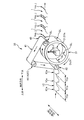
- FIG. 10 is a schematic perspective view of a production apparatus 30 used in the production line.
- the manufacturing apparatus 30 includes a diaper continuous body 1 ⁇ / b> C in which the unfolded diapers 1, 1... In FIG. It is conveyed in a state folded in two in the vertical direction.
- the portion 1Ce which becomes the lateral end 1e of the diaper 1 in the same continuum 1C is the upper end portion 1eu of the aforementioned 8-layer structure and the first intermediate portions 1em1 and 5 of the 6-layer structure.
- the second intermediate portion 1em2 having a layer structure and the lower end portion 1ed having a four-layer structure are provided.
- the CD direction is defined as a direction orthogonal to the transport direction, but the continuum 1C has the longitudinal direction orthogonal to the continuous direction of the continuum 1C along the CD direction.
- the continuous direction is transported as the transport direction.
- the position between the parts 1Cp and 1Cp which become adjacent diapers in the continuous direction is irradiated as the irradiation target position, and thereby the continuous body 1C is irradiated. It is divided at the same position to form the aforementioned edge 1ee, and the abdomen 11a and the back 11b are fused to form a linear fused portion j on the edge 1ee.
- a pants-type diaper 1 is manufactured.
- the manufacturing apparatus 30 includes a rotary drum 31 that is driven to rotate about a rotation axis along the CD direction, and an endless belt member that is provided on the outer peripheral side of the rotary drum 31 and rotates around the rotary drum 31 in synchronization with the drive rotation operation. 41 and a laser beam irradiation device 51 disposed on the inner peripheral side of the rotary drum 31.
- the rotating drum 31 rotates in synchronization with the movement of the continuous body 1C in a state where the continuous body 1C conveyed from the upper process is wound around the outer peripheral surface of the drum 31 at a predetermined winding angle. Thereby, the rotating drum 31 conveys the continuum 1C along a predetermined arc trajectory based on the winding angle. Further, slits SL, SL,... Along the CD direction are formed through the portion of the outer peripheral surface of the drum 31 facing the irradiation target position of the continuum 1C. Therefore, the laser beam irradiation device 51 can irradiate the laser beam LZ from the inner peripheral side of the rotating drum 31 to the irradiation target position of the continuous body 1C without any problem.
- the endless belt member 41 clamps the continuous body 1C moving along the circular arc track in the thickness direction in cooperation with the outer peripheral surface of the rotary drum 31, thereby stabilizing the conveyance state of the continuous body 1C. To do.
- the endless belt member 41 is wound around a plurality of rollers 43, 43... Arranged on the outer peripheral side of the rotary drum 31. And at least one roller 43 of these rollers 43, 43... Is a drive roller 43D, and the endless belt member 41 is driven around by obtaining a rotational force from the roller 43D.
- the laser beam irradiation device 51 applies the laser beam LZ to the irradiation target position in the continuum 1C while the continuum 1C moves on the arc orbit while being sandwiched between the outer peripheral surface of the rotating drum 31 and the endless belt member 41. Irradiate. As a result, the diaper portion 1Cp is divided from the continuum 1C to form an edge 1ee, and a fused portion j is formed at the edge 1ee.
- the laser beam irradiation device 51 includes an irradiation head 51h that can move the spot of the laser beam LZ in the CD direction and the rotation direction Dc31 of the rotary drum 31, and a control unit (not shown) that controls the irradiation head 51h.
- a control unit (not shown) that controls the irradiation head 51h.
- the continuum 1C that moves along the circular arc trajectory is cut along the CD direction at the irradiation target position.
- a biaxial galvano scanner can be cited as the irradiation head 51h having such a function.
- the galvano scanner includes a light source of the laser beam LZ, a lens, and a galvanometer mirror that changes the irradiation direction of the laser beam LZ in two directions, and can thereby scan the laser beam LZ in two directions.
- the light source an appropriate light source can be used as long as the continuous body 1C to be cut can be cut.
- a diode type or a CO 2 type may be used.
- the operation of the irradiation head 51h is controlled so that the energy level (J / m or W / m) of the laser beam LZ injected per unit length in the CD direction is constant.
- the energy level (J / m or W / m) of the laser beam LZ injected per unit length in the CD direction is constant.
- the amount of energy may be changed according to the position in the CD direction, such as increasing or decreasing the amount of energy to be input according to the number of stacked layers. However, at any position in the CD direction, at least the energy required for cutting the continuous body 1C is input.
- the continuous body 1C is irradiated with the laser beam LZ while sandwiching the continuous body 1C between the outer peripheral surface of the rotating drum 31 and the endless belt member 41, and thereby the continuous body 1C.
- the fusion part j was formed while dividing 1C.
- the larger the difference in the number of stacked layers between the first part and the second part adjacent to each other in the CD direction in the continuum 1C the lateral tearing occurs. Is more likely to occur.
- the clamping state of the second portion where the number of stacked layers is small in the vicinity of the boundary position between the first portion and the second portion may be excessively weakened, and this makes it difficult for the second portion to be fused.
- the divergence between the fusion strength of the fusion part of the second part with a small number of laminations and the fusion strength of the fusion part of the first part with a large number of laminations further proceeds, and as a result, It becomes easier to split laterally at the boundary position with the second part.
- the 8-layer structure portion, the 6-layer structure portion, the 5-layer structure portion, and the 4-layer structure portion are arranged in the CD direction. That is, in the continuum 1C, the difference in the number of stacked layers has many boundary positions. Therefore, according to this continuous body 1C, the diaper 1 in which transverse tearing hardly occurs even when the fusion processing is performed by the manufacturing apparatus 30 described above can be manufactured.
- Generation of such a continuous body 1C that is, generation of a continuous body 1C immediately before being conveyed to the manufacturing apparatus 30 of FIG. 10, more specifically, in a portion 1Ce that becomes the lateral end 1e of the diaper 1, Generation of a diaper continuum 1C having the above-described upper end portion 1eu having an eight-layer structure, a first intermediate portion 1em1 having a six-layer structure, a second intermediate portion 1em2 having a five-layer structure, and a lower end portion 1ed having a four-layer structure Is performed as follows, for example.
- both the inner layer sheet 12 and the outer layer sheet 13 forming the exterior sheet 11 are in a continuous sheet state continuous in the conveying direction, but here, the continuous sheet CD of the inner layer sheet 12
- the dimension in the CD direction of the continuous sheet of the outer layer sheet 13 is made larger than the dimension in the direction, and more specifically, an end corresponding to the ventral part 11a and an end corresponding to the back part 11b in the CD direction.
- the amount of protrusion of the continuous sheet of the outer layer sheet 13 protruding outward in the CD direction from the continuous sheet of the inner layer sheet 12 is compared with the former protrusion amount (the end corresponding to the ventral portion 11a).
- the latter amount of protrusion (the amount of protrusion at the end corresponding to the back side portion 11b) is larger than the amount of protrusion at. Further, a plurality of continuous bodies of thread-like elastic members 15 along the transport direction are inserted between the continuous sheet of the inner layer sheet 12 and the continuous sheet of the outer layer sheet 13 in the CD direction.
- seat 11 passes the merge position of the absorptive main body 3 set to the predetermined position of a conveyance direction, However, At the time of this passage, the diaper 1 of the diaper 1 in a conveyance direction is carried out on the skin side surface of the said continuous sheet. A plurality of absorbent main bodies 3, 3... Are placed and fixed at the product pitch. As a result, an unfolded continuum in which the unfolded diapers 1, 1... Are continuous in the lateral direction of the diaper 1 is generated.
- the continuum passes through a position of a well-known bending guide member (not shown) provided downstream of the above-mentioned merging position.
- a well-known bending guide member (not shown) provided downstream of the above-mentioned merging position.
- both ends of the continuous sheet of the exterior sheet 11 in the CD direction are folded back inward in the CD direction by the bending guide member.
- the end corresponding to the back side portion 11b is folded back larger than the end corresponding to the ventral side portion 11a.
- the continuous body passes through a well-known bi-fold processing apparatus (not shown) provided downstream of the bending guide member. At that time, the device is folded in half so that the edge portions in the CD direction of the continuous sheet of the exterior sheet 11 overlap in the thickness direction. And the continuous body 1C of the diaper to which the above-mentioned layer structure was provided is produced
- FIG. 11A to FIG. 11D are explanatory views of a first modification to a fourth modification of the diaper 1 of the present embodiment.
- 11A to 11D are diagrams corresponding to FIG. 5B according to the present embodiment, that is, schematic views taken along line BB in FIG. 5A.
- the longitudinal tip position P12bt of the folded back portion 12bt of the inner layer sheet 12 in the back side portion 11b (the position of the end on the leg opening 1HL side, the bottom end in the longitudinal direction).
- Position) and the front end position P12at in the vertical direction of the folded portion 12at of the inner layer sheet 12 in the ventral portion 11a (the position of the end on the leg opening 1HL side, the lower end position in the vertical direction) are aligned
- the first modification is mainly different in that the positions P12bt and P12at are different from each other as shown in FIG. 11A. That is, the former tip position P12bt is positioned lower in the vertical direction than the latter tip position P12at.
- a portion P7 having a seven-layer structure is added between the portion P8 having an eight-layer structure and the portion P6 having a six-layer structure at the lateral end 1e.
- the end portion 1e includes an 8-layer structure portion P8, a 7-layer structure portion P7, a 6-layer structure portion P6, a 5-layer structure portion P5, and a 4-layer structure portion P4.
- the above-mentioned five portions P8, P7, P6, P5, and P4 are different from each other in the vertical direction by only one layer. Not limited to. That is, the number of stacked layers may differ by one between the four portions and the portions adjacent in the vertical direction.
- the folded portion 13at (13bt) of the outer layer sheet 13 is folded back of the inner layer sheet 12 for both the abdominal side portion 11a and the back side portion 11b.
- the folded portion 12at (12bt) of the inner layer sheet 12 is more outward than the outer leg layer 12HL (12bt).
- the first difference is that the folded portion 13at (13bt) of the sheet 13 protrudes toward the leg opening 1HL in the vertical direction.
- the longitudinal tip position P12bt of the folded portion 12bt of the inner layer sheet 12 in the back side portion 11b and the inner layer sheet 12 in the ventral side portion 11a are folded.
- the front end position P12at in the vertical direction of the portion 12at is aligned, in the second modified example of FIG. 11B, as shown in FIG. 11B, these positions P12bt and P12at are different from each other.
- the former position P12bt is different from the latter position P12at in that the former position P12bt is located on the side of the longitudinal leg processing portion 1HL.
- the lateral end 1e of the diaper 1 includes the 8-layer structure portion P8, the 6-layer structure portion P6, the 5-layer structure portion P5, and the 4-layer structure portion P4. Are arranged in this order from top to bottom in the vertical direction.
- both the inner layer sheet 12 and the outer layer sheet 13 which form the exterior sheet 11 are folded back about both the abdominal side part 11a and the back side part 11b.
- the folded portions 12at and 13at (12bt and 13bt) are formed in the sheets 12 and 13, respectively.
- the ventral portion 11a is formed in the third modified example of FIG. 11C.
- the back side portion 11b is mainly different in that only the outer layer sheet 13 is folded and the inner layer sheet 12 is not folded.
- the outer layer sheet 13 is folded downward in the vertical direction with a predetermined position in the vertical direction as a bending position for both the abdominal side portion 11a and the back side portion 11b.
- the bent portion 13am (13bm) is formed at the bending position, and the folded portion 13at (13bt) is superimposed on the skin side surface of the inner layer sheet 12 from the skin side.
- the upper end edge portion 12eu of the inner layer sheet 12 is in contact with the bent portion 13am (13bm) of the outer layer sheet 13 from the valley fold side.
- the folded portion 13bt of the outer layer sheet 13 of the back side portion 11b protrudes toward the longitudinal leg opening 1HL side of the folded portion 13at of the outer layer sheet 13 of the ventral portion 11a.
- the portion P8 having an eight-layer structure is eliminated at the lateral end 1e of the diaper 1. That is, the end portion 1e has a six-layer structure portion P6 as the upper end portion 1eu, has a five-layer structure portion P5 as the intermediate portion 1em, and has a four-layer structure portion P4 as the lower end portion 1ed. ing. Therefore, the upper end portion 1eu, the intermediate portion 1em, and the lower end portion 1ed are in a state in which the number of stacked layers differs from the portion adjacent in the vertical direction by one. Therefore, an abrupt change in the fusion strength of the fusion part j is suppressed over substantially the entire length in the longitudinal direction of the end part 1e.
- the upper edge 12eu of the inner layer sheet 12 is brought into contact with the bent portion 13am (13bm) of the outer layer sheet 13 from the valley fold side for each of the abdominal side portion 11a and the back side portion 11b.
- the upper end edge 12eu of the inner layer sheet 12 may be shifted and disposed below the position of the bent portion 13am (13bm) of the outer layer sheet 13.
- the part P4 of the 4 layer structure is additionally provided as the upper end part 1eu in the edge part 1e of the horizontal direction of the diaper 1.
- the end portion 1e has a four-layer structure portion P4, a six-layer structure portion P6, a five-layer structure portion P5, and a four-layer structure portion P4 in the vertical direction. Are arranged in this order from the top to the bottom.
- the two-piece type diaper 1 is illustrated in which the absorbent main body 3 as the first part is covered with the exterior sheet 11 having a substantially hourglass shape in plan view as the second part from the non-skin side.
- the pants-type absorbent article may be a so-called 3-piece type diaper 1a. Details are as follows.
- this diaper 1a has the absorptive main body 3 distribute
- the absorbent main body 3 is stretched between them, End portions 3ea and 3eb in the longitudinal direction of the absorbent main body 3 are bonded and fixed to the nearest band members 21a and 21b, respectively, and the external shape is substantially H-shaped in plan view. Therefore, from this expanded state, the absorbent main body 3 is folded in half at the substantially central portion 3m in the longitudinal direction, and the band members 21a and 21b that are overlapped with each other in the folded state are orthogonal to the longitudinal direction.
- a pant-type diaper 1a as shown in FIG. 12B is formed. That is, the end portions 1ae and 1ae of the pants-type diaper 1a are formed on both sides in the lateral direction by the above-described joining, and the band members 21a and 21b are connected in a ring shape, thereby The waist opening 1aBL is formed above the direction, and the pair of leg openings 1aHL, 1aHL are formed below the same vertical direction.
- the end portion 1ae has a plurality of portions arranged in the vertical direction, and the number of stacked sheets forming the ventral belt member 21a and the back belt member 21b is the first of the plurality of portions.
- the portion and the second portion located next to the first portion in the longitudinal direction are different from each other by only one sheet.
- the edge portion 1 aee along the longitudinal direction has a ventral band.
- the fusion part j formed by fusing the member 21a and the back band member 21b may continuously extend in a line shape along the edge 1aee.
- the first intermediate portion 1em1 is illustrated as the first portion
- the second intermediate portion 1em2 is illustrated as the second portion.
- the present invention is not limited to this. That is, if two portions are adjacent to each other in the vertical direction at the lateral end 1e of the diaper 1 and the number of stacked layers is different from each other by one, these two portions are referred to as the first portion. It can be understood as a part and a second part.
- the second intermediate portion 1em2 may be regarded as the first portion
- the lower end portion 1ed may be regarded as the second portion.
- both end portions 11aeL and 11beL in the longitudinal direction of the exterior sheet 11 are folded back inward in the longitudinal direction, but the present invention is not limited to this. That is, only one of the both end portions 11aeL and 11beL may be folded, or neither may be folded. When neither of them is folded, for example, the size of the inner layer sheet 12 in the longitudinal direction (longitudinal direction) is different from that of the outer layer sheet 13 in the longitudinal direction (vertical direction).
- the first portion and the second portion which are different from each other in the number of stacked layers, are formed adjacent to each other in the longitudinal direction at the end portion 1e in the direction.
- the exterior sheet 11 is a sheet having a two-layer structure including the inner layer sheet 12 and the outer layer sheet 13, but is not limited thereto. That is, a single-layer sheet having only one sheet or a sheet having a structure of three or more layers having three or more sheets may be used.
- the portion where the longitudinal end of the absorbent main body 3 is located in the ventral side portion 11 a of the exterior sheet 11, and the absorbent main body in the dorsal side portion 11 b. 3 a buffer sheet (so-called treatment sheet) separate from the inner layer sheet 12 and the outer layer sheet 13 was not provided for the portion where the end in the longitudinal direction is located. You may join a sheet
- this buffer sheet is a part in which the said edge part is located in the ventral part 11a or the part in which the said edge part is located in the back side part 11b resulting from presence of each edge part of the longitudinal direction of the absorptive main body 3.
- it is a sheet that relieves the tight contact with the skin of the wearer, and a flexible thermoplastic sheet such as a nonwoven fabric is used as the material thereof.
- the cushion sheet has, for example, a belt shape along the lateral direction (width direction) of the diaper 1, and the cushion sheet extends the abdominal side portion 11 a or the back side portion 11 b in the lateral direction (width direction). It is provided to cover.
- seat since the said buffer sheet
- the first portion and the second portion which are different from each other in the number of stacked layers, are adjacent to each other in the longitudinal direction 1e. Any diaper 1 formed together is included in the scope of the present invention.
Landscapes
- Health & Medical Sciences (AREA)
- Epidemiology (AREA)
- Engineering & Computer Science (AREA)
- Biomedical Technology (AREA)
- Heart & Thoracic Surgery (AREA)
- Vascular Medicine (AREA)
- Life Sciences & Earth Sciences (AREA)
- Animal Behavior & Ethology (AREA)
- General Health & Medical Sciences (AREA)
- Public Health (AREA)
- Veterinary Medicine (AREA)
- Absorbent Articles And Supports Therefor (AREA)
Abstract
装着時に着用者の腹側に配される腹側部と、前記着用者の背側に配される背側部と、前記着用者の股間に配される股下部とを有した吸収性物品が、前記股下部にて二つ折りされて前記腹側部と前記背側部とが重ね合わせられた状態で、前記腹側部と前記背側部とが前記吸収性物品の横方向の各端部に相当する部分でそれぞれ融着されていることにより、前記横方向と交差する縦方向において互いに異なる位置に、胴回り開口部と一対の脚回り開口部とが形成されたパンツ型の吸収性物品である。前記各端部を、それぞれ前記縦方向に複数の部分に区分した場合に、前記腹側部及び前記背側部を形成するシートの積層枚数が、前記複数の部分のうちの第1部分と、該第1部分の前記縦方向の隣に位置する第2部分とで、互いに一枚だけ相違している。前記複数の部分において前記縦方向に沿った縁部には、前記腹側部と前記背側部とが融着されてなる融着部が、前記縁部に沿った線状に連続して延在している。
Description
本発明は、尿等の排泄物を吸収するパンツ型の吸収性物品、及びその製造方法に関する。
従来、尿等の排泄物を吸収する吸収性物品として、パンツ型の使い捨ておむつが使用されている。このおむつは、装着時に着用者の腹側に配される腹側部と、同着用者の背側に配される背側部と、同着用者の股間に配される股下部とを展開状態において有する。そして、かかる展開状態のおむつが、股下部にて二つ折りされて腹側部と背側部とが重ね合わせられた状態で、当該腹側部と背側部とがおむつの横方向の各端部に相当する部分でそれぞれ融着されることにより、胴回り開口部と一対の脚回り開口部とが形成されて、これにより、当該おむつは、パンツ型の状態にされる。そして、かかるパンツ型の状態でおむつはユーザーに提供される。
特許文献1には、このパンツ型のおむつの一例が開示されている。図1Aは、同おむつ1’の横方向の端部1e’の概略拡大図であり、また、図1Bは、図1A中のB-B矢視の概略図である。図1Aに示すように、このおむつ1’にあっては、上述の腹側部11a’と背側部11b’とが、おむつ1’の横方向の各端部1e’に相当する部分11aew’,11bew’で融着されて接合されていて、これにより、各端部1e’の縁部1ee’には融着部j’が形成されている(図1A中のドット模様の部分を参照)。かかる融着部j’はレーザー光線を照射することにより、上記縁部1ee’で腹側部11a’と背側部11b’とを融かして形成される。そして、これにより、かかる融着部j’は、胴回り開口部1HB’の方から脚回り開口部1HL’の方へと縁部1ee’に沿って線状に連続して延在している。また、排泄後におむつ1’を着用者から脱がす際には、当該融着部j’において腹側部11a’と背側部11b’とを引き剥がして分離することがなされる。
一方、同文献1には、図1Bに示すように、上記の横方向の各端部1e’に、腹側部11a’及び背側部11b’を形成するシートの積層枚数の合計値が8枚の部分と4枚の部分とを縦方向に並んで有したおむつ1’が開示されている。すなわち、腹側部11a’及び背側部11b’は、どちらも二枚のシートが積層されたシート部材であるとともに、同シート部材は、胴回り開口部1HB’をなす上端部で折り返されていて、これにより、当該端部1e’の上半部1eu’は、シートの積層枚数が8枚の部分とされ、その下方の下半部1ed’は、シートの積層枚数が4枚の部分とされている。
しかしながら、前述のように、融着部j’は腹側部11a’及び背側部11b’を融かして形成されることから、8枚の部分に形成される融着部j8’の融着強度は、4枚の部分に形成される融着部j4’の融着強度よりも一般に過大となる。
そのため、おむつ1’の交換をすべく融着部j’で腹側部11a’と背側部11b’とを引き剥がす際には、図1Aに示す8枚の部分と4枚の部分との境界位置BL’で融着強度が急激に変化することから、当該境界位置BL’等で、融着部j’に沿って引き剥がすために付与する力が、横方向の内方を向いた力Fin’に転じ易く、その結果、腹側部11a’又は背側部11b’を横方向の内側に引き裂いてしまう恐れがある。つまり、横裂きしてしまう恐れがある。すると、おむつ1’の腹側部11a’又は背側部11b’を大きく破損してしまい得て、その結果、おむつ交換の際に、排泄物の大きな漏れを招き得る。
また、かかる横裂きは、上述のように、融着部j’の形態が上記縁部1ee’に沿って線状に連続した形態の場合に起き易い。すなわち、一般に、ヒートシールや超音波シール等のように適宜な融着パターンで融着された形態の融着部(不図示)と比較して、上記のような縁部1ee’に沿った線状の融着部j’の場合には、当該融着部j’の横方向の寸法Ljw’が、例えば0.5mm~3mmという具合に非常に小さくなっている。そのため、当該線状の融着部j’に沿って腹側部11a’と背側部11b’とを引き剥がす際には、引き剥がすために付与する力が、当該線状の融着部j’から横方向の内側により一層脱線し易い(図1A中に太線矢印Finを参照)。そして、その結果、腹側部11a’又は背側部11b’を横方向の内側により一層引き裂いてしまい易い。
本発明は、上記のような従来の問題に鑑みてなされたものであって、その目的は、線状に連続する融着部で腹側部と背側部とを引き剥がす際に起こり得る横裂きを抑制することにある。
上記目的を達成するための主たる発明は、
装着時に着用者の腹側に配される腹側部と、前記着用者の背側に配される背側部と、前記着用者の股間に配される股下部とを有した吸収性物品が、前記股下部にて二つ折りされて前記腹側部と前記背側部とが重ね合わせられた状態で、前記腹側部と前記背側部とが前記吸収性物品の横方向の各端部に相当する部分でそれぞれ融着されていることにより、前記横方向と交差する縦方向において互いに異なる位置に、胴回り開口部と一対の脚回り開口部とが形成されたパンツ型の吸収性物品であって、
前記各端部を、それぞれ前記縦方向に複数の部分に区分した場合に、前記腹側部及び前記背側部を形成するシートの積層枚数が、前記複数の部分のうちの第1部分と、該第1部分の前記縦方向の隣に位置する第2部分とで、互いに一枚だけ相違しており、
前記複数の部分において前記縦方向に沿った縁部には、前記腹側部と前記背側部とが融着されてなる融着部が、前記縁部に沿った線状に連続して延在していることを特徴とするパンツ型の吸収性物品である。
装着時に着用者の腹側に配される腹側部と、前記着用者の背側に配される背側部と、前記着用者の股間に配される股下部とを有した吸収性物品が、前記股下部にて二つ折りされて前記腹側部と前記背側部とが重ね合わせられた状態で、前記腹側部と前記背側部とが前記吸収性物品の横方向の各端部に相当する部分でそれぞれ融着されていることにより、前記横方向と交差する縦方向において互いに異なる位置に、胴回り開口部と一対の脚回り開口部とが形成されたパンツ型の吸収性物品であって、
前記各端部を、それぞれ前記縦方向に複数の部分に区分した場合に、前記腹側部及び前記背側部を形成するシートの積層枚数が、前記複数の部分のうちの第1部分と、該第1部分の前記縦方向の隣に位置する第2部分とで、互いに一枚だけ相違しており、
前記複数の部分において前記縦方向に沿った縁部には、前記腹側部と前記背側部とが融着されてなる融着部が、前記縁部に沿った線状に連続して延在していることを特徴とするパンツ型の吸収性物品である。
また、
装着時に着用者の腹側に配される腹側部と、前記着用者の背側に配される背側部と、前記着用者の股間に配される股下部とを有した吸収性物品が、前記股下部にて二つ折りされて前記腹側部と前記背側部とが重ね合わせられた状態で、前記腹側部と前記背側部とが前記吸収性物品の横方向の各端部に相当する部分でそれぞれ融着されていることにより、前記横方向と交差する縦方向において互いに異なる位置に、胴回り開口部と一対の脚回り開口部とが形成されたパンツ型の吸収性物品の製造方法であって、
前記パンツ型の吸収性物品の前記各端部を、それぞれ前記縦方向に複数の部分に区分した場合に、前記腹側部及び前記背側部を形成するシートの積層枚数が、前記複数の部分のうちの第1部分と、該第1部分の前記縦方向の隣に位置する第2部分とで、互いに一枚だけ相違しており、
前記縦方向に二つ折りされた状態の前記パンツ型の吸収性物品となる部分が前記横方向に複数連続した状態の連続体を、前記横方向を搬送方向として搬送することと、
前記連続体において前記複数の部分に相当する位置にレーザー光線を照射することにより、前記複数の部分で前記連続体を分断して前記複数の部分に前記縦方向に沿った縁部を形成するとともに、前記パンツ型の吸収性物品となる部分の前記腹側部と前記背側部とを融着して、前記縁部に、当該縁部に沿って連続して延在する線状の融着部を形成することと、を有することを特徴とするパンツ型の吸収性物品の製造方法である。
装着時に着用者の腹側に配される腹側部と、前記着用者の背側に配される背側部と、前記着用者の股間に配される股下部とを有した吸収性物品が、前記股下部にて二つ折りされて前記腹側部と前記背側部とが重ね合わせられた状態で、前記腹側部と前記背側部とが前記吸収性物品の横方向の各端部に相当する部分でそれぞれ融着されていることにより、前記横方向と交差する縦方向において互いに異なる位置に、胴回り開口部と一対の脚回り開口部とが形成されたパンツ型の吸収性物品の製造方法であって、
前記パンツ型の吸収性物品の前記各端部を、それぞれ前記縦方向に複数の部分に区分した場合に、前記腹側部及び前記背側部を形成するシートの積層枚数が、前記複数の部分のうちの第1部分と、該第1部分の前記縦方向の隣に位置する第2部分とで、互いに一枚だけ相違しており、
前記縦方向に二つ折りされた状態の前記パンツ型の吸収性物品となる部分が前記横方向に複数連続した状態の連続体を、前記横方向を搬送方向として搬送することと、
前記連続体において前記複数の部分に相当する位置にレーザー光線を照射することにより、前記複数の部分で前記連続体を分断して前記複数の部分に前記縦方向に沿った縁部を形成するとともに、前記パンツ型の吸収性物品となる部分の前記腹側部と前記背側部とを融着して、前記縁部に、当該縁部に沿って連続して延在する線状の融着部を形成することと、を有することを特徴とするパンツ型の吸収性物品の製造方法である。
本発明の他の特徴については、本明細書及び添付図面の記載により明らかにする。
本発明によれば、線状に連続する融着部で腹側部と背側部とを引き剥がす際に起こり得る横裂きを抑制することができる。
本明細書及び添付図面の記載により、少なくとも以下の事項が明らかとなる。
装着時に着用者の腹側に配される腹側部と、前記着用者の背側に配される背側部と、前記着用者の股間に配される股下部とを有した吸収性物品が、前記股下部にて二つ折りされて前記腹側部と前記背側部とが重ね合わせられた状態で、前記腹側部と前記背側部とが前記吸収性物品の横方向の各端部に相当する部分でそれぞれ融着されていることにより、前記横方向と交差する縦方向において互いに異なる位置に、胴回り開口部と一対の脚回り開口部とが形成されたパンツ型の吸収性物品であって、
前記各端部を、それぞれ前記縦方向に複数の部分に区分した場合に、前記腹側部及び前記背側部を形成するシートの積層枚数が、前記複数の部分のうちの第1部分と、該第1部分の前記縦方向の隣に位置する第2部分とで、互いに一枚だけ相違しており、
前記複数の部分において前記縦方向に沿った縁部には、前記腹側部と前記背側部とが融着されてなる融着部が、前記縁部に沿った線状に連続して延在していることを特徴とするパンツ型の吸収性物品である。
前記各端部を、それぞれ前記縦方向に複数の部分に区分した場合に、前記腹側部及び前記背側部を形成するシートの積層枚数が、前記複数の部分のうちの第1部分と、該第1部分の前記縦方向の隣に位置する第2部分とで、互いに一枚だけ相違しており、
前記複数の部分において前記縦方向に沿った縁部には、前記腹側部と前記背側部とが融着されてなる融着部が、前記縁部に沿った線状に連続して延在していることを特徴とするパンツ型の吸収性物品である。
このようなパンツ型の吸収性物品によれば、上記端部に係る上記複数の部分は、縦方向に隣り合う第1部分と第2部分とを有し、これら第1部分と第2部分とは、互いの積層枚数が一枚だけ相違している。よって、第1部分の融着部と第2部分の融着部との境界位置での融着強度の急激な変化を抑制できる。そして、これにより、融着部において腹側部と背側部とを引き剥がす際に、第1部分の融着部と第2部分との融着部の境界位置等において円滑に腹側部と背側部とを引き剥がすことができて、結果、横裂きを抑制することができる。
かかるパンツ型の吸収性物品であって、
前記第2部分よりも前記第1部分の方が、前記縦方向の前記胴回り開口部側に位置しており、
前記複数の部分は、前記第2部分の前記縦方向の前記脚回り開口部側に隣接して第3部分を有し、
前記第2部分と前記第3部分とは、互いの前記積層枚数が一枚だけ相違しているのが望ましい。
前記第2部分よりも前記第1部分の方が、前記縦方向の前記胴回り開口部側に位置しており、
前記複数の部分は、前記第2部分の前記縦方向の前記脚回り開口部側に隣接して第3部分を有し、
前記第2部分と前記第3部分とは、互いの前記積層枚数が一枚だけ相違しているのが望ましい。
このようなパンツ型の吸収性物品によれば、第2部分に隣接する第3部分の積層枚数も、第2部分の積層枚数と一枚だけ相違している。よって、第2部分の融着部と第3部分の融着部との境界位置での融着強度の急激な変化を抑制できて、その結果、融着部において腹側部と背側部とを引き剥がす際に起こり得る横裂きをより確実に抑制可能となる。
かかるパンツ型の吸収性物品であって、
前記各端部は、それぞれ前記複数の部分として少なくとも3つの部分を有し、
前記縦方向に沿って前記胴回り開口部から前記脚回り開口部へ向かうに従って、前記複数の部分の前記積層枚数は漸減しているのが望ましい。
前記各端部は、それぞれ前記複数の部分として少なくとも3つの部分を有し、
前記縦方向に沿って前記胴回り開口部から前記脚回り開口部へ向かうに従って、前記複数の部分の前記積層枚数は漸減しているのが望ましい。
このようなパンツ型の吸収性物品によれば、上記端部に係る上記複数の部分の積層枚数は、縦方向に沿って漸減している。よって、縦方向の略全長に亘って融着部の融着強度の急激な変化は抑制される。そして、これにより、融着部で腹側部と背側部とを引き剥がす際に起こり得る横裂きをより確実に抑制可能となる。
かかるパンツ型の吸収性物品であって、
前記各端部は、それぞれ前記複数の部分として少なくとも4つの部分を有し、
前記複数の部分は、それぞれ、前記縦方向に隣り合う部分との間で前記積層枚数が一枚だけ相違しているのが望ましい。
前記各端部は、それぞれ前記複数の部分として少なくとも4つの部分を有し、
前記複数の部分は、それぞれ、前記縦方向に隣り合う部分との間で前記積層枚数が一枚だけ相違しているのが望ましい。
このようなパンツ型の吸収性物品によれば、上記端部に係る上記複数の部分は、少なくとも4つの部分を有し、そして、上記複数の部分は、それぞれ、縦方向に隣り合う部分との間で積層枚数が一枚だけ相違している。よって、縦方向の略全長に亘って融着部の融着強度の急激な変化は抑制される。そして、これにより、融着部で腹側部と背側部とを引き剥がす際に起こり得る横裂きをより確実に抑制可能となる。
かかるパンツ型の吸収性物品であって、
前記腹側部及び前記背側部は、それぞれ、前記横方向に沿った複数の糸状弾性部材を前記縦方向に並んで有し、
前記第1部分よりも前記第2部分の方が、前記縦方向の前記脚回り開口部側に位置しているとともに、前記第2部分の前記積層枚数の方が前記第1部分の前記積層枚数よりも一枚少なく、
少なくとも前記第2部分の前記融着部には、前記糸状弾性部材が存在していないのが望ましい。
前記腹側部及び前記背側部は、それぞれ、前記横方向に沿った複数の糸状弾性部材を前記縦方向に並んで有し、
前記第1部分よりも前記第2部分の方が、前記縦方向の前記脚回り開口部側に位置しているとともに、前記第2部分の前記積層枚数の方が前記第1部分の前記積層枚数よりも一枚少なく、
少なくとも前記第2部分の前記融着部には、前記糸状弾性部材が存在していないのが望ましい。
このようなパンツ型の吸収性物品によれば、上記の糸状弾性部材が、少なくとも第2部分の融着部には存在していない。よって、当該糸状弾性部材の存在起因で第2部分の融着部の融着強度が低下してしまう事態を速やかに回避することができる。その結果、そもそも積層枚数が一枚少ないことに基づいて既に第1部分の融着部よりも低くなっている第2部分の融着部の融着強度の更なる低下を抑制することができて、これにより、第1部分の融着部と第2部分の融着部との間の融着強度の更なる乖離を抑制可能となる。よって、第1部分の融着部と第2部分の融着部との融着強度の急激な変化を効果的に抑制することができる。
かかるパンツ型の吸収性物品であって、
前記腹側部及び前記背側部において前記第2部分と前記縦方向の位置が同じ部分には、前記糸状弾性部材が配置されていないのが望ましい。
前記腹側部及び前記背側部において前記第2部分と前記縦方向の位置が同じ部分には、前記糸状弾性部材が配置されていないのが望ましい。
このようなパンツ型の吸収性物品によれば、上記第2部分の融着部に糸状弾性部材が確実に存在しないようにすることができる。
かかるパンツ型の吸収性物品であって、
前記腹側部及び前記背側部において前記第2部分と前記縦方向の位置が同じ部分には、前記糸状弾性部材が配置されているとともに、前記糸状弾性部材の前記横方向の端部は、前記第2部分の前記融着部よりも前記横方向の内側に位置しているのが望ましい。
前記腹側部及び前記背側部において前記第2部分と前記縦方向の位置が同じ部分には、前記糸状弾性部材が配置されているとともに、前記糸状弾性部材の前記横方向の端部は、前記第2部分の前記融着部よりも前記横方向の内側に位置しているのが望ましい。
このようなパンツ型の吸収性物品によれば、上記第2部分の融着部に糸状弾性部材が確実に存在しないようにすることができる。
かかるパンツ型の吸収性物品であって、
前記第1部分よりも前記第2部分の方が、前記縦方向の前記脚回り開口部側に位置しているとともに、前記第2部分の前記積層枚数の方が前記第1部分の前記積層枚数よりも一枚少なく、
前記腹側部及び前記背側部は、複数枚のシートが厚さ方向に積層されて形成されており、
前記複数枚のシート同士を圧着するための複数の圧着部が、前記厚さ方向にへこみつつ前記縦方向及び前記横方向に非連続に形成されており、
前記圧着部が、少なくとも前記第2部分の前記融着部に存在していないのが望ましい。
前記第1部分よりも前記第2部分の方が、前記縦方向の前記脚回り開口部側に位置しているとともに、前記第2部分の前記積層枚数の方が前記第1部分の前記積層枚数よりも一枚少なく、
前記腹側部及び前記背側部は、複数枚のシートが厚さ方向に積層されて形成されており、
前記複数枚のシート同士を圧着するための複数の圧着部が、前記厚さ方向にへこみつつ前記縦方向及び前記横方向に非連続に形成されており、
前記圧着部が、少なくとも前記第2部分の前記融着部に存在していないのが望ましい。
このようなパンツ型の吸収性物品によれば、上記の圧着部は、少なくとも第2部分の融着部には存在していない。よって、当該圧着部の存在起因で第2部分の融着部に空間が形成されてしまって融着強度が低下してしまう事態を速やかに回避することができる。その結果、そもそも積層枚数が一枚少ないことに基づいて既に第1部分の融着部よりも低くなっている第2部分の融着部の融着強度の更なる低下を抑制することができて、これにより、第1部分の融着部と第2部分の融着部との間の融着強度の更なる乖離を抑制可能となる。よって、第1部分の融着部と第2部分の融着部との融着強度の急激な変化を効果的に抑制することができる。
かかるパンツ型の吸収性物品であって、
前記腹側部を形成するシートが前記縦方向に折り返されて前記胴回り開口部の位置に折り曲げ部が形成されているとともに、折り返された部分は、前記シートに肌側から重ね合わせられつつ接着剤で前記シートに固定されており、
前記背側部を形成するシートが前記縦方向に折り返されて前記胴回り開口部の位置に折り曲げ部が形成されているとともに、折り返された部分は、前記シートに肌側から重ね合わせられつつ接着剤で前記シートに固定されており、
前記腹側部に係る前記折り返された部分と前記背側部に係る前記折り返された部分とのうちの一方が、他方よりも前記縦方向の前記脚回り開口部の方へ突出することにより、前記第2部分が形成されているとともに、前記第2部分の前記縦方向の前記胴回り開口部側に隣接して前記第1部分が形成されており、
前記腹側部に係る前記折り返された部分の前記接着剤の塗布領域であって前記第1部分に位置する前記塗布領域と、前記背側部に係る前記折り返された部分の前記接着剤の塗布領域であって前記第1部分に位置する前記塗布領域とは、前記縦方向に関してオーバーラップしているのが望ましい。
前記腹側部を形成するシートが前記縦方向に折り返されて前記胴回り開口部の位置に折り曲げ部が形成されているとともに、折り返された部分は、前記シートに肌側から重ね合わせられつつ接着剤で前記シートに固定されており、
前記背側部を形成するシートが前記縦方向に折り返されて前記胴回り開口部の位置に折り曲げ部が形成されているとともに、折り返された部分は、前記シートに肌側から重ね合わせられつつ接着剤で前記シートに固定されており、
前記腹側部に係る前記折り返された部分と前記背側部に係る前記折り返された部分とのうちの一方が、他方よりも前記縦方向の前記脚回り開口部の方へ突出することにより、前記第2部分が形成されているとともに、前記第2部分の前記縦方向の前記胴回り開口部側に隣接して前記第1部分が形成されており、
前記腹側部に係る前記折り返された部分の前記接着剤の塗布領域であって前記第1部分に位置する前記塗布領域と、前記背側部に係る前記折り返された部分の前記接着剤の塗布領域であって前記第1部分に位置する前記塗布領域とは、前記縦方向に関してオーバーラップしているのが望ましい。
このようなパンツ型の吸収性物品によれば、腹側部に係る上記折り返された部分の接着剤の塗布領域であって第1部分に位置する塗布領域と、背側部に係る上記折り返された部分の接着剤の塗布領域であって第1部分に位置する塗布領域とは、縦方向に関してオーバーラップしている。よって、胴回り開口部を起点として融着部において腹側部と背側部とを引き剥がす際に、腹側部に係る上記折り返された部分が背側部に持って行かれてしまう事態、或いは逆に、背側部に係る上記折り返された部分が腹側部に持って行かれてしまう事態の発生を防ぐことができる。そして、これにより、この持って行かれてしまう事態が、第1部分の融着部と第2部分の融着部との境界位置等で起こり得る横裂きのきっかけとなることを有効に防ぐことができて、その結果、横裂きの抑制効果を更に高めることができる。
かかるパンツ型の吸収性物品であって、
前記腹側部を形成するシートが前記縦方向に折り返されて前記胴回り開口部の位置に折り曲げ部が形成されているとともに、折り返された部分は、前記シートに肌側から重ね合わせられつつ接着剤で前記シートに固定されており、
前記背側部を形成するシートが前記縦方向に折り返されて前記胴回り開口部の位置に折り曲げ部が形成されているとともに、折り返された部分は、前記シートに肌側から重ね合わせられつつ接着剤で前記シートに固定されており、
前記腹側部に係る前記折り返された部分よりも前記背側部に係る前記折り返された部分の方が、前記縦方向の前記脚回り開口部の方へ突出することにより、前記第2部分が形成されているとともに、前記第2部分の前記縦方向の前記胴回り開口部側に隣接して前記第1部分が形成されているのが望ましい。
前記腹側部を形成するシートが前記縦方向に折り返されて前記胴回り開口部の位置に折り曲げ部が形成されているとともに、折り返された部分は、前記シートに肌側から重ね合わせられつつ接着剤で前記シートに固定されており、
前記背側部を形成するシートが前記縦方向に折り返されて前記胴回り開口部の位置に折り曲げ部が形成されているとともに、折り返された部分は、前記シートに肌側から重ね合わせられつつ接着剤で前記シートに固定されており、
前記腹側部に係る前記折り返された部分よりも前記背側部に係る前記折り返された部分の方が、前記縦方向の前記脚回り開口部の方へ突出することにより、前記第2部分が形成されているとともに、前記第2部分の前記縦方向の前記胴回り開口部側に隣接して前記第1部分が形成されているのが望ましい。
このようなパンツ型の吸収性物品によれば、腹側部に係る上記折り返された部分よりも背側部に係る上記折り返された部分の方が、縦方向に沿って脚回り開口部の方に突出している。よって、腹側部の横裂きよりも背側部の横裂きの方を優先して抑制可能であり、その結果、吸収性物品の交換時に背側部の横裂き起因で軟便等の大便が漏出することを防ぐことができる。
また、
装着時に着用者の腹側に配される腹側部と、前記着用者の背側に配される背側部と、前記着用者の股間に配される股下部とを有した吸収性物品が、前記股下部にて二つ折りされて前記腹側部と前記背側部とが重ね合わせられた状態で、前記腹側部と前記背側部とが前記吸収性物品の横方向の各端部に相当する部分でそれぞれ融着されていることにより、前記横方向と交差する縦方向において互いに異なる位置に、胴回り開口部と一対の脚回り開口部とが形成されたパンツ型の吸収性物品の製造方法であって、
前記パンツ型の吸収性物品の前記各端部を、それぞれ前記縦方向に複数の部分に区分した場合に、前記腹側部及び前記背側部を形成するシートの積層枚数が、前記複数の部分のうちの第1部分と、該第1部分の前記縦方向の隣に位置する第2部分とで、互いに一枚だけ相違しており、
前記縦方向に二つ折りされた状態の前記パンツ型の吸収性物品となる部分が前記横方向に複数連続した状態の連続体を、前記横方向を搬送方向として搬送することと、
前記連続体において前記複数の部分に相当する位置にレーザー光線を照射することにより、前記複数の部分で前記連続体を分断して前記複数の部分に前記縦方向に沿った縁部を形成するとともに、前記パンツ型の吸収性物品となる部分の前記腹側部と前記背側部とを融着して、前記縁部に、当該縁部に沿って連続して延在する線状の融着部を形成することと、を有することを特徴とするパンツ型の吸収性物品の製造方法である。
装着時に着用者の腹側に配される腹側部と、前記着用者の背側に配される背側部と、前記着用者の股間に配される股下部とを有した吸収性物品が、前記股下部にて二つ折りされて前記腹側部と前記背側部とが重ね合わせられた状態で、前記腹側部と前記背側部とが前記吸収性物品の横方向の各端部に相当する部分でそれぞれ融着されていることにより、前記横方向と交差する縦方向において互いに異なる位置に、胴回り開口部と一対の脚回り開口部とが形成されたパンツ型の吸収性物品の製造方法であって、
前記パンツ型の吸収性物品の前記各端部を、それぞれ前記縦方向に複数の部分に区分した場合に、前記腹側部及び前記背側部を形成するシートの積層枚数が、前記複数の部分のうちの第1部分と、該第1部分の前記縦方向の隣に位置する第2部分とで、互いに一枚だけ相違しており、
前記縦方向に二つ折りされた状態の前記パンツ型の吸収性物品となる部分が前記横方向に複数連続した状態の連続体を、前記横方向を搬送方向として搬送することと、
前記連続体において前記複数の部分に相当する位置にレーザー光線を照射することにより、前記複数の部分で前記連続体を分断して前記複数の部分に前記縦方向に沿った縁部を形成するとともに、前記パンツ型の吸収性物品となる部分の前記腹側部と前記背側部とを融着して、前記縁部に、当該縁部に沿って連続して延在する線状の融着部を形成することと、を有することを特徴とするパンツ型の吸収性物品の製造方法である。
このようなパンツ型の吸収性物品の製造方法によれば、前述の作用効果を奏するパンツ型の吸収性物品を製造可能となる。
===本実施形態===
図2は、本実施形態のパンツ型の吸収性物品の一例としてのパンツ型の使い捨ておむつ1の概略斜視図である。図3Aは、展開状態のおむつ1を肌側から見た概略平面図であり、図3Bは、図3A中のB-B矢視の概略図である。また、図4は、展開状態のおむつ1を分解して示す概略斜視図である。
図2は、本実施形態のパンツ型の吸収性物品の一例としてのパンツ型の使い捨ておむつ1の概略斜視図である。図3Aは、展開状態のおむつ1を肌側から見た概略平面図であり、図3Bは、図3A中のB-B矢視の概略図である。また、図4は、展開状態のおむつ1を分解して示す概略斜視図である。
なお、以下の説明では、おむつ1が着用者に装着された際に、当該着用者の肌側に位置すべき側のことを単に「肌側」と言い、他方、着用者の非肌側に位置すべき側のことを単に「非肌側」と言う。
図3Aに示すように、このおむつ1は、例えば2ピースタイプのおむつ1である。すなわち、同おむつ1は、尿などの排泄物を吸収する例えば平面視略長方形形状の吸収性本体3を第1部品として有し、そして、上記吸収性本体3の非肌側面を覆って設けられておむつ1の外装をなす平面視略砂時計形状の外装シート11を第2部品として有している。
図3A、図3B、及び図4に示すように、吸収性本体3は、排泄物を吸収する吸収性コア2cを有する。吸収性コア2cは、パルプ繊維等の液体吸収性繊維や高吸収性ポリマー等の液体吸収性粒状物を、所定形状の一例としての平面視略砂時計形状に成形したものである。なお、同コア2cは、必要に応じてティッシュペーパー等の液透過性の被覆シートで被覆されていても良い。
かかる吸収性コア2cの肌側面には、当該面を全面に亘って覆うように不織布等の液透過性のトップシート4が設けられており、同様に、同吸収性コア2cの非肌側面には、当該面を全面に亘って覆うようにフィルム等の液不透過性の防漏シート5が設けられている。ここで、この例では、どちらのシート4,5も、平面視略長方形形状に形成されており、また、どちらのシート4,5も、吸収性コア2cの外形輪郭から全周に亘って外方に突出している。そして、トップシート4において突出した部分と防漏シート5において突出した部分とが、互いに接着や溶着等によって接合されていて、その結果、平面視略長方形形状の吸収性本体3が形成されている。
なお、不図示であるが、かかる吸収性本体3の幅方向の両端部に対して、それぞれ、同本体3の長手方向に沿って糸ゴム等の糸状弾性部材を設けても良い。かかる糸状弾性部材は、吸収性本体3及び外装シート11における脚回り開口部1HLの近傍部分に伸縮性を付与するものである。よって、かかる弾性部材は、トップシート4と防漏シート5との間に介挿されつつ、自然長から所定倍率まで伸長された状態でホットメルト接着剤により両シート4,5に固定される。
また、場合によっては、尿の横漏れを防止する目的で防漏壁部(不図示)を吸収性本体3に設けても良い。かかる防漏壁部は、立体ギャザーとも呼ばれる周知のものであり、例えば不織布等の柔軟なシートを材料として、吸収性本体3の肌側面等の両端部にそれぞれ起立するように設けられる。
外装シート11は、図3Aの展開状態においては、平面視略砂時計形状の柔軟なシートであり、同シート11は、互いに直交する三方向として、厚さ方向と長手方向と幅方向とを有している。また、当該外装シート11は、長手方向に関して三つの部分11a,11b,11cに区分される。すなわち、外装シート11は、着用者の腹側に配される腹側部11aと、着用者の背側に配される背側部11bと、着用者の股間に配される股下部11cとに区分される。ちなみに、股下部11cは、腹側部11aと背側部11bとの間に位置していて、これにより、当該股下部11cは、平面視略砂時計形状において幅方向に括れた形状の部分11cとなっている。
図3B及び図4に示すように、かかる外装シート11には、二層構造のシート11が使用されている。すなわち、当該外装シート11は、おむつ1の着用時に主に着用者の肌側を向いて内層をなす内層シート12と、同着用時に主に非肌側を向いて外層をなす外層シート13と、を有し、かかる内層シート12と外層シート13とは、厚さ方向に重ね合わせられつつ圧着で接合されている。そのため、外装シート11には、厚さ方向の両側からへこんだ形状の複数の圧着部eb,eb…(図2乃至図4では不図示のため、図8を参照)が、長手方向及び幅方向のそれぞれについて非連続に分散した格子状パターン等の適宜な配置パターンで形成されている。
なお、かかる内層シート12及び外層シート13の材料には、それぞれ、熱可塑性樹脂繊維を含む不織布や熱可塑性樹脂フィルム等が使用される。そして、この例では、前者の内層シート12の材料として、17(g/m2)の坪量のスパンボンド不織布が使用されており、他方、後者の外層シート13の材料として、5(g/m2)の坪量のSMS不織布(スパンボンド/メルトブローン/スパンボンド不織布)が使用されているが、何等これに限らない。
また、図3A乃至図4に示すように、内層シート12と外層シート13との間には、糸ゴム等の糸状弾性部材15,15…が介挿されている。かかる糸状弾性部材15,15…は、外装シート11の腹側部11a及び背側部11bに対して幅方向の伸縮性を付与するものである。そのため、当該糸状弾性部材15,15…は、自然長から所定倍率まで伸長された状態で幅方向に沿って配置されつつ、ホットメルト接着剤により展開状態の各シート12,13に固定されている。かかる糸状弾性部材15,15…は、外装シート11の長手方向に並んで互いの間に間隔をあけながら複数本配置されており、これにより、腹側部11a及び背側部11bのそれぞれについて上記長手方向の広範囲に亘って伸縮性が付与されている。
更に、かかる外装シート11の長手方向の各端部11aeL,11beLたる腹側部11aの端部11aeL及び背側部11bの端部11beLには、それぞれ、折り返された部分11at,11btが設けられている。すなわち、外装シート11は、腹側部11aの端部11aeL及び背側部11bの端部11beLのそれぞれにおいて、長手方向の所定位置を折り曲げ位置として長手方向の内側に折り返されていて、これにより、当該折り曲げ位置に折り曲げ部11am,11bmが形成されているととともに、折り返された部分11at,11btは、同外装シート11の肌側面に肌側から重ね合わせられつつホットメルト接着剤で固定されている。そして、腹側部11aの端部11aeLで折り返された部分11atの長手方向の長さL11atと、背側部11bの端部11beLで折り返された部分11btの長手方向の長さL11btとは互いに相違していて、この例では、後者の長さL11btの方が前者の長さL11atよりも長くなっている。また、かかる折り返された部分11at,11btにおける長手方向の長さは、外装シート11を形成する内層シート12と外層シート13との間でも互いに相違していて、この例では、腹側部11aの端部11aeL及び背側部11bの端部11beLの両方において、それぞれ、外層シート13の折り返された部分13at(13bt)の長手方向の長さL13at(L13bt)の方が内層シート12の折り返された部分12at(12bt)の長手方向の長さL12at(L12bt)よりも長くなっている。そして、これにより、図3A及び図3Bのように、外層シート13の折り返された部分13at(13bt)の長手方向の先端位置P13at(P13bt)の方が内層シート12の折り返された部分12at(12bt)の長手方向の先端位置P12at(P12bt)よりも脚回り開口部1HL側に位置している。
そして、このような外装シート11の肌側面には、図3A及び図3Bに示すように、吸収性本体3がホットメルト接着剤で固定されて、これにより、同図3Aの展開状態のおむつ1が生成される。そして、この展開状態のおむつ1を、股下部11cで二つ折りして腹側部11aと背側部11bとを重ね合わせて、この重ね合わせた状態において、腹側部11aと背側部11bとを、おむつ1の幅方向の各端部1eに相当する部分11aew,11bewでそれぞれ接合することにより、図2に示すような胴回り開口部1HBと一対の脚回り開口部1HL,1HLとが形成されたパンツ型のおむつ1の形態にされる。
なお、以下では、同図2の如くパンツ型にされたおむつ1の三次元形状の方向について、次のように定義する。先ず、外装シート11の幅方向と平行な方向のことを「横方向」と言う。また、外装シート11の長手方向と平行な方向のことを「縦方向」と言う。横方向と縦方向とは直交している。また、横方向と縦方向との両者と直交する方向のことを「前後方向」と言う。なお、前後方向の前方が、着用者の前側たる腹側であり、同前後方向の後方が、着用者の後側たる背側である。また、おむつ1を装着した際には、上記の縦方向は上下方向を向くことから、縦方向のことを「上下方向」とも言う。ちなみに、上下方向で言えば、脚回り開口部1HLは、胴回り開口部1HBよりも下方に位置している。更に、横方向のことを「左右方向」とも言う。
図5Aは、おむつ1における横方向の端部1eの概略拡大図であり、図5Bは、図5A中のB-B矢視の概略図である。
上述の端部1eでの接合は、レーザー光線の照射による融着処理でなされている。すなわち、かかる融着処理により、外装シート11の腹側部11aと背側部11bとは、おむつ1の横方向の端部1eに相当する部分11aew,11bewで融着されている。そして、この融着の痕跡として、各端部1eにおける縦方向に沿った縁部1eeには、それぞれ、融着部jが、上記縁部1eeに沿った線状に連続して延在している(図5A中のドット模様の部分を参照)。詳しくは、同融着部jは、横方向に例えば0.5mm~3mmの寸法Ljwで、且つ、胴回り開口部1HBの位置から脚回り開口部1HLの位置までの範囲たる縁部1eeの縦方向の略全長に亘って延在している。
また、図5Bに示すように、当該横方向の端部1eは、外装シート11の内層シート12及び外層シート13が複数枚積層されて形成されている。そして、これらシート12,13の積層枚数に注目すると、当該端部1eは、積層枚数が互いに異なる四つの部分1eu,1em1,1em2,1ed(複数の部分に相当)を縦方向に並んで有している。
すなわち、前述のように外装シート11の長手方向の各端部11aeL,11beLたる腹側部11aの端部11aeL及び背側部11bの端部11beL同士が、折り返される部分11at,11btの長さL11at,L11btを互いに相違させながらそれぞれ縦方向に折り返されていたことや、外装シート11を形成する内層シート12と外層シート13との間でも縦方向に折り返される部分12at,13at(12bt,13bt)同士の長さL12at,L13at(L12bt,L13bt)が互いに異なっていたこと等に起因して、図5Bに示すように、上記の横方向の端部1eは、上端部分1eu(最も胴回り開口部1HB側の部分)として、8枚のシートが積層された8層構造の部分を有し、その下方に隣接する第1中間部分1em1として、6枚のシートが積層された6層構造の部分を有し、更に、その下方に隣接する第2中間部分1em2として、5枚のシートが積層された5層構造の部分を有し、そして最後に、その下方に隣接する下端部分1ed(最も脚回り開口部1HL側の部分)として、4枚のシートが積層された4層構造の部分を有している。
更に詳しく説明すると、先ず、上端部分1euでは、腹側部11aについては内層シート12と外層シート13とがそれぞれ折り返された四層構造となっているとともに、背側部11bについても内層シート12と外層シート13とがそれぞれ折り返された四層構造となっていて、これにより、上端部分1euは、合計8層構造となっている。一方、第1中間部分1em1では、腹側部11aの内層シート12の折り返された部分12atが無くなっているとともに、背側部11bの内層シート12の折り返された部分12btも無くなっていることから、上述の8層構造から2層だけ少なくなった6層構造となっている。更に、第2中間部分1em2では、腹側部11aの外層シート13の折り返された部分13atが無くなっていることから、上述の6層構造から1層だけ少なくなった5層構造となっている。そして、最後の下端部分1edでは、背側部11bの外層シート13の折り返された部分13btも無くなっていることから、上述の5層構造から1層だけ少なくなった4層構造となっている。
そして、かかる端部1eの構造によれば、融着部jで腹側部11aと背側部11bとを引き剥がす際に起こり得る横裂きを抑制することができる。すなわち、図5Bに示すように、第1中間部分1em1(第1部分に相当)と、その縦方向の下方の隣に位置する第2中間部分1em2(第2部分に相当)とは、積層枚数が一枚だけ相違しており、また、第2中間部分1em2(第2部分に相当)と、その縦方向の下方の隣に位置する下端部分1ed(第3部分に相当)とについても、積層枚数が一枚だけ相違している。そのため、図5Aに示すように、第1中間部分1em1の融着部j1と第2中間部分1em2の融着部j2との境界位置BLj1j2での融着強度の急激な変化を抑制できて、また、同様に、第2中間部分1em2の融着部j2と下端部分1edの融着部jdとの境界位置BLj2jdでの融着強度の急激な変化も抑制できる。そして、これにより、融着部jにおいて腹側部11aと背側部11bとを引き剥がす際に、第1中間部分1em1の融着部j1と第2中間部分1em2の融着部j2との境界位置BLj1j2、及び、第2中間部分1em2の融着部j2と下端部分1edの融着部jdとの境界位置BLj2jdにおいて、それぞれ円滑に腹側部11aと背側部11bとを引き剥がすことができて、その結果、当該境界位置BLj1j2,BLj2jd等で起こり得る横裂きを有効に抑制することができる。
ちなみに、この例では、図5Bに示すように、第2中間部分1em2と下端部分1edとの間の積層枚数の差は、一枚とされていたが、何等これに限らず、二枚以上としても良い。すなわち、少なくとも第1中間部分1em1と第2中間部分1em2との間の積層枚数の差が一枚とされていれば、少なくとも当該第1中間部分1em1の融着部j1と第2中間部分1em2の融着部j2との境界位置BLj1j2(図5A)においては円滑に腹側部11aと背側部11bとを引き剥がすことができる。そのため、第2中間部分1em2と下端部分1edとの間の積層枚数の差については、二枚以上としても良い。但し、そのようにした場合には、全体的に横裂きの抑制効果が小さくなってしまうので、望ましくは、同図5Bの例のように第2中間部分1em2と下端部分1edとの間の積層枚数の差についても、一枚にすると良い。
また、この例では、同図5Bに示すように、縦方向に沿って胴回り開口部1HBから脚回り開口部1HLへ向かうに従って、横方向の端部1eにおける上記4つの部分1eu,1em1,1em2,1edの積層枚数は漸減している。すなわち、上端部分1euの積層枚数は8枚であり、第1中間部分1em1の積層枚数は6枚であり、第2中間部分1em2の積層枚数は5枚であり、下端部分1edの積層枚数は4枚であり、これにより、積層枚数は縦方向の上方から下方に向かうに従って漸減している。よって、縦方向の略全長に亘って融着部jの融着強度の急激な変化は抑制される。そして、これにより、融着部jで腹側部11aと背側部11bとを引き剥がす際に起こり得る横裂きをより確実に抑制可能となる。
更に、この例では、図6A及び図6Bに示すように、外装シート11の腹側部11a及び背側部11bに配された複数の糸状弾性部材15,15…が、少なくとも第2中間部分1em2の融着部j2には存在していない。すなわち、この例では、糸状弾性部材15,15…は、その端部15eが融着部jよりも横方向の内側(図6Aでは左側)に位置するように配置されていて、これにより、第2中間部分1em2の融着部j2には糸状弾性部材15が存在していない。
よって、当該糸状弾性部材15の存在起因で第2中間部分1em2の融着部j2の融着強度が低下してしまう事態を速やかに回避することができる。その結果、そもそも積層枚数が一枚少ないことに基づいて既に第1中間部分1em1の融着部j1よりも低くなっている第2中間部分1em2の融着部j2の融着強度の更なる低下を抑制することができて、これにより、第1中間部分1em1の融着部j1と第2中間部分1em2の融着部j2との間の融着強度の更なる乖離を抑制可能となる。よって第1中間部分1em1の融着部j1と第2中間部分1em2の融着部j2との境界位置BLj1j2での融着強度の急激な変化を効果的に抑制することができる。
ちなみに、この例では、図6Aに示すように、全ての糸状弾性部材15,15…について、その端部15eが、融着部jよりも横方向の内側(図6Aでは左側)に位置するように各糸状弾性部材15,15…は配置されていて、これにより、上端部分1eu、第1中間部分1em1、及び下端部分1edについても、融着部ju,j1,jdに糸状弾性部材15,15…が存在していないが、何等これに限らない。例えば、上端部分1euの融着部juには糸状弾性部材15を存在させても良いし、更に言えば、第1中間部分1em1の融着部j1や下端部分1edの融着部jdにも糸状弾性部材15を存在させても良い。
また、場合によっては、糸状弾性部材15が第2中間部分1em2の融着部j2に存在しないようにすることを、図7A及び図7Bに示すように、腹側部11a及び背側部11bにおいて第2中間部分1em2と縦方向の位置が同じ部分に、糸状弾性部材15を全く配置しないことで実現しても良い。
ちなみに、この図7Aの例では、腹側部11a及び背側部11bにおいて上端部分1euと縦方向の位置が同じ部分、同じく第1中間部分1em1と縦方向の位置が同じ部分、同じく下端部分1edと縦方向の位置が同じ部分については、それぞれ、糸状弾性部材15,15…が配置されていて、更に、これら上端部分1euの融着部ju、第1中間部分1em1の融着部j1、及び下端部分1edの融着部jdにも、それぞれ、糸状弾性部材15,15…が存在しているが、何等これに限らない。すなわち、糸状弾性部材15,15…の端部15e,15e…を、対応する各融着部ju,j1,jdよりも横方向の内側に位置させることにより、各融着部ju,j1,jdに糸状弾性部材15,15…が存在しないようにしても良い。
更に、この例では、図3Bの外装シート11を形成する内層シート12と外層シート13とは、図8に示すように、複数の圧着部eb,eb…で圧着されていたが、同図8を参照してわかるように、かかる圧着部ebは、少なくとも第2中間部分1em2の融着部j2には存在していない。よって、当該圧着部ebの存在起因で第2中間部分1em2の融着部j2に空間が形成されてしまって融着強度が低下してしまう事態を速やかに回避することができる。その結果、そもそも積層枚数が一枚少ないことに基づいて既に第1中間部分1em1の融着部j1よりも低くなっている第2中間部分1em2の融着部j2の融着強度の更なる低下を抑制することができて、これにより、第1中間部分1em1の融着部j1と第2中間部分1em2の融着部j2との間の融着強度の更なる乖離を抑制可能となる。よって、第1中間部分1em1の融着部j1と第2中間部分1em2の融着部j2との境界位置BLj1j2での融着強度の急激な変化を効果的に抑制することができる。
また、この例では、図9A及び図9Bに示すように、腹側部11aに係る折り返された部分11atは、ホットメルト接着剤HMAaで腹側部11aの肌側面に固定されているが、かかるホットメルト接着剤HMAaは、例えば横方向に沿った帯状の塗布領域Aa,Aa…が縦方向に複数並んで配された塗布パターンで塗布されている。一方、同様に、背側部11bに係る折り返された部分11btも、ホットメルト接着剤HMAbで背側部11bの肌側面に固定されているが、かかるホットメルト接着剤HMAbも、例えば横方向に沿った帯状の塗布領域Ab,Ab…(図9Aでは不図示)が縦方向に複数並んで配された塗布パターンで塗布されている。そして、ここで、腹側部11aの複数の塗布領域Aa,Aa…のうちで第1中間部分1em1に位置する塗布領域Aaと、背側部11bの複数の塗布領域Ab,Ab…のうちで第1中間部分1em1に位置する塗布領域Abとは、縦方向に関して互いにオーバーラップしている。
よって、胴回り開口部1HLを起点としつつ腹側部11aと背側部11bとを融着部jで引き剥がす際に、腹側部11aに係る上記折り返された部分11atが背側部11bに持って行かれてしまう事態、或いは逆に、背側部11bに係る上記折り返された部分11btが腹側部11aに持って行かれてしまう事態の発生を確実に防ぐことができる。そして、これにより、この持って行かれてしまう事態が、第1中間部分1em1の融着部j1と第2中間部分1em2の融着部j2との境界位置BLj1j2で起こり得る横裂きのきっかけとなることを有効に防ぐことができる。
ちなみに、この図9Aの例では、塗布パターンの塗布領域の一例として横方向に沿った帯状の塗布領域Aa,Abを示したが、何等これに限らない。例えば、塗布領域が、横方向に沿ったスパイラル状でも良いし、これ以外の形状でも良い。また、この例では、腹側部11aの塗布領域Aaの形状と背側部11bの塗布領域Abの形状とが互いに同形であったが、何等これに限らない。すなわち、一方が帯状で他方がスパイラル状といった具合に、互いの形状が異なっていても良い。
更に、この例では、図5Bに示すように、腹側部11aに係る折り返された部分11atよりも背側部11bに係る折り返された部分11btの方が、縦方向の脚回り開口部1HLの方へ突出している。よって、腹側部11aの横裂きよりも背側部11bの横裂きの方を優先して抑制可能であり、その結果、おむつ1の交換時に背側部11bの横裂き起因で軟便等の大便が漏出することを防ぐことができる。
このようなおむつ1は、製造ラインで製造される。図10は、同製造ラインで使用される製造装置30の概略斜視図である。
同図10に示すように、この製造装置30には、図3Aの展開状態のおむつ1,1…が同おむつ1の横方向に複数連続してなるおむつの連続体1Cが、同おむつ1の縦方向に二つ折りされた状態で搬送される。そして、この二つ折りの状態では、同連続体1Cにおいておむつ1の横方向の端部1eとなる部分1Ceは、前述の8層構造の上端部分1euと6層構造の第1中間部分1em1と5層構造の第2中間部分1em2と4層構造の下端部分1edとを有した状態になっている。また、製造ラインには、搬送方向と直交する方向としてCD方向が規定されているが、同連続体1Cは、当該連続体1Cの連続方向と直交する上記の縦方向をCD方向に沿わせた姿勢で、連続方向を搬送方向として搬送される。そして、図10の製造装置30では、当該連続体1Cにおいて連続方向に隣り合うおむつとなる部分1Cp,1Cp同士の間の位置を照射対象位置としてレーザー光線LZを照射し、これにより、連続体1Cを同位置で分断して、前述の縁部1eeを形成するとともに、腹側部11aと背側部11bとを融着して縁部1eeに線状の融着部jを形成し、その結果、パンツ型のおむつ1が製造される。
製造装置30は、CD方向に沿った回転軸回りに駆動回転する回転ドラム31と、回転ドラム31の外周側に設けられて、回転ドラム31の駆動回転動作と同期して駆動周回する無端ベルト部材41と、回転ドラム31の内周側に配置されたレーザー光線照射装置51と、を有する。
回転ドラム31は、上工程から搬送される上記連続体1Cを同ドラム31の外周面に所定の巻き付け角度で巻き付けた状態で同連続体1Cの移動と同期して回転する。そして、これにより、回転ドラム31は、上記の巻き付け角度に基づく所定の円弧軌道に沿って同連続体1Cを搬送する。また、同ドラム31の外周面において上記連続体1Cの照射対象位置と対向する部分には、CD方向に沿ったスリットSL,SL…が貫通形成されている。よって、レーザー光線照射装置51は、回転ドラム31の内周側から連続体1Cの照射対象位置へとレーザー光線LZを問題無く照射可能である。
無端ベルト部材41は、上記の円弧軌道に沿って移動している連続体1Cを回転ドラム31の外周面と共同して厚さ方向に挟圧し、これにより、連続体1Cの搬送状態を安定化する。かかる無端ベルト部材41は、回転ドラム31の外周側に配された複数のローラー43,43…に掛け回されていている。そして、これらローラー43,43…のうちの少なくとも一本のローラー43は駆動ローラー43Dであり、当該ローラー43Dから回転力を得て無端ベルト部材41は駆動周回する。
レーザー光線照射装置51は、回転ドラム31の外周面と無端ベルト部材41とで挟圧されながら連続体1Cが上記の円弧軌道を移動する間に、同連続体1Cにおける上記照射対象位置にレーザー光線LZを照射する。そして、これにより、前述の連続体1Cからおむつとなる部分1Cpが分断されて縁部1eeが形成されるとともに同縁部1eeに融着部jが形成される。
かかるレーザー光線照射装置51は、レーザー光線LZのスポットをCD方向及び回転ドラム31の回転方向Dc31に移動可能な照射ヘッド51hと、照射ヘッド51hを制御する制御部(不図示)と、を有する。そして、これにより、円弧軌道に沿って移動する連続体1Cを照射対象位置でCD方向に沿って切断する。かかる機能の照射ヘッド51hとしては、例えば、2軸タイプのガルバノスキャナを挙げることができる。すなわち、同ガルバノスキャナは、レーザー光線LZの光源と、レンズと、レーザー光線LZの照射方向を二方向に変更するガルバノミラーと、を有し、これにより、レーザー光線LZを二方向に走査可能である。なお、上記の光源については、切断対象の上記連続体1Cを切断可能であれば、適宜な光源を使用可能であり、例えば、ダイオードタイプを用いても良いし、CO2タイプを用いても良い。また、この例では、CD方向の単位長さ当たりに投入されるレーザー光線LZのエネルギーの大きさ(J/m又はW/m)が一定となるように同照射ヘッド51hの動作が制御されているが、何等これに限らない。例えば、積層枚数の多少に応じて、投入するエネルギーの大きさを増減させる等、CD方向の位置に応じて、エネルギーの大きさを変化させても良い。但し、CD方向の何れの位置においても、少なくとも連続体1Cの切断に必要な大きさのエネルギーが投入される。
ところで、この製造装置30では、上述のように、回転ドラム31の外周面と無端ベルト部材41とで連続体1Cを挟圧しながら同連続体1Cにレーザー光線LZを照射し、これにより、同連続体1Cを分断しながら融着部jを形成していたが、この手法では、連続体1CにおいてCD方向に隣り合う第1部分と第2部分とで互いの積層枚数の差が大きい程、横裂きが起き易くなる。例えば、第1部分の積層枚数よりも第2部分の積層枚数の方が少ない場合には、第1部分と第2部分との境界位置の近傍で、積層枚数が少ない第2部分の挟圧状態(圧縮状態)が過度に弱まってしまい得て、これにより、当該第2部分が融着し難くなる。すると、積層枚数が少ない第2部分の融着部の融着強度と、積層枚数が多い第1部分の融着部の融着強度との乖離が更に進んでしまい、その結果、第1部分と第2部分との境界位置で更に横裂きし易くなってしまう。
しかし、この点につき、この例の連続体1Cの場合には、上述のように、CD方向に並んで8層構造の部分と6層構造の部分と5層構造の部分と4層構造の部分とを有していて、つまり、当該連続体1Cには、積層枚数の差が一枚の境界位置が多い。よって、この連続体1Cによれば、上述の製造装置30で融着処理した場合でも、横裂けが起き難いおむつ1を製造することができる。
かような連続体1Cの生成、すなわち、図10の製造装置30に搬送される直前の状態の連続体1Cの生成、更に詳しくは、おむつ1の横方向の端部1eとなる部分1Ceに、前述の8層構造の上端部分1euと6層構造の第1中間部分1em1と5層構造の第2中間部分1em2と4層構造の下端部分1edとを有した状態のおむつの連続体1Cの生成は、例えば、次のようにしてなされる。
先ず、同装置30の搬送方向の上流側では、上記の連続体1Cの材料として、複数の外装シート11,11…がおむつ1の横方向に連続してなる外装シート11の連続シート(不図示)が、連続方向を搬送方向に沿わせつつ、同連続方向と交差する同シートの幅方向をCD方向に沿わせた姿勢で搬送されている。そして、この時点では、当然ながら、外装シート11を形成する内層シート12及び外層シート13のどちらも、搬送方向に連続した連続シートの状態にあるが、ここで、内層シート12の連続シートのCD方向の寸法よりも外層シート13の連続シートのCD方向の寸法の方が大きくされており、更に言えば、CD方向において腹側部11aに相当する端部と背側部11bに相当する端部との両者で、内層シート12の連続シートからCD方向の外方に突出する外層シート13の連続シートの突出量を大小比較した場合に、前者の突出量(腹側部11aに相当する端部での突出量)よりも後者の突出量(背側部11bに相当する端部での突出量)の方が大きくなっている。また、内層シート12の連続シートと外層シート13の連続シートとの間には、搬送方向に沿った糸状弾性部材15の連続体がCD方向に複数並んで介挿された状態となっている。
そして、かかる外装シート11の連続シートは、搬送方向の所定位置に設定された吸収性本体3の合流位置を通過するが、この通過時には、同連続シートの肌側面に、搬送方向におむつ1の製品ピッチで複数の吸収性本体3,3…が載置されて固定される。そして、これにより、展開状態の複数のおむつ1,1…が同おむつ1の横方向に連続してなる展開状態の連続体が生成される。
次に、同連続体は、上記の合流位置の下流に設けられた周知の折り曲げガイド部材(不図示)の位置を通過する。そして、その際には、当該折り曲げガイド部材によって、外装シート11の連続シートのCD方向の両端部がCD方向の内側にそれぞれ折り返される。しかも、このときには、背側部11bに相当する端部の方が腹側部11aに相当する端部よりも大きく折り返される。
そうしたら、最後に、その折り返された状態のまま、同連続体は、折り曲げガイド部材の下流に設けられた周知の二つ折り処理装置(不図示)を通過する。そして、その際には、同装置によって、外装シート11の連続シートのCD方向の各端縁部同士が厚さ方向に重なるように二つ折りされる。そして、当該二つ折りにより、上述の層構造が付与されたおむつの連続体1Cが生成される(図10)。
図11A乃至図11Dは、本実施形態のおむつ1の第1変形例乃至第4変形例の説明図である。なお、図11A乃至図11Dの何れの図も、本実施形態に係る図5Bに相当する図であり、つまり、図5A中のB-B矢視の概略図である。
前述の実施形態では、図5Bに示すように、背側部11bにおける内層シート12の折り返された部分12btの縦方向の先端位置P12bt(脚回り開口部1HL側の端の位置、縦方向の下端位置)と、腹側部11aにおける内層シート12の折り返された部分12atの縦方向の先端位置P12at(脚回り開口部1HL側の端の位置、縦方向の下端位置)とが揃っていたが、この第1変形例では、図11Aに示すように、これらの位置P12bt,P12at同士が相違している点で主に相違する。すなわち、前者の先端位置P12btの方が、後者の先端位置P12atよりも縦方向の下方に位置している。そして、この相違に基づいて、当該第1変形例では、横方向の端部1eにおける8層構造の部分P8と6層構造の部分P6との間には、7層構造の部分P7が追加されていて、その結果、当該端部1eは、8層構造の部分P8と、7層構造の部分P7と、6層構造の部分P6と、5層構造の部分P5と、4層構造の部分P4とを、縦方向の上方から下方へとこの順番で並んで有している。つまり、上記の各部分P8,P7,P6,P5,P4は、それぞれ、縦方向に隣り合う部分との間で積層枚数が一枚だけ相違した状態となっている。
よって、同端部1eの縦方向の略全長に亘って融着部jの融着強度の急激な変化は抑制される。そして、これにより、融着部jで腹側部11aと背側部11bとを引き剥がす際に起こり得る横裂きをより確実に抑制可能となる。なお、これ以外の点については、前述の実施形態と概ね同じであるので、その説明については省略する。ちなみに、この第1変形例では、上記の5つの部分P8,P7,P6,P5,P4が、それぞれ縦方向に隣り合う部分との間で積層枚数が一枚だけ相違していたが、何等これに限らない。すなわち、4つの部分が、それぞれ縦方向に隣り合う部分との間で積層枚数が一枚だけ相違していても良い。
一方、前述の実施形態では、図5Bに示すように、腹側部11a及び背側部11bのどちらについても、外層シート13の折り返された部分13at(13bt)の方が、内層シート12の折り返された部分12at(12bt)よりも縦方向の脚回り開口部1HLの方に突出していたが、図11Bの第2変形例では、内層シート12の折り返された部分12at(12bt)の方が外層シート13の折り返された部分13at(13bt)よりも縦方向の脚回り開口部1HL側に突出している点で先ず相違する。また、前述の実施形態では、図5Bに示すように、背側部11bにおける内層シート12の折り返された部分12btの縦方向の先端位置P12btと、腹側部11aにおける内層シート12の折り返された部分12atの縦方向の先端位置P12atとが揃っていたが、この図11Bの第2変形例では、図11Bに示すように、これらの位置P12bt,P12at同士が互いに相違していて、より詳しくは、前者の位置P12btの方が後者の位置P12atよりも縦方向の脚回り加工部1HL側に位置している点で相違する。更に、前述の実施形態では、図5Bに示すように、腹側部11aと背側部11bとで、外層シート13の折り返された部分13at,13btの縦方向の先端位置P13at,P13bt同士が互いに揃っていなかったが、この図11Bの第2変形例では、腹側部11aと背側部11bとで、外層シート13の折り返された部分13at,13btの縦方向の先端位置P13at,P13bt同士が互いに揃っている点でも相違する。そして、これら以外の点は概ね前述の実施形態と同じである。よって、この第2変形例でも、おむつ1の横方向の端部1eは、8層構造の部分P8と、6層構造の部分P6と、5層構造の部分P5と、4層構造の部分P4とを、縦方向の上方から下方へとこの順番で並んで有している。
また、図5Bに示すように、前述の実施形態では、腹側部11a及び背側部11bのどちらについても、外装シート11を形成する内層シート12と外層シート13との両方が折り返されていて、これにより、各シート12,13には、それぞれ、折り返された部分12at,13at(12bt,13bt)が形成されていたが、この点につき、図11Cの第3変形例では、腹側部11a及び背側部11bのどちらについても、外層シート13のみが折り返されていて内層シート12は折り返されていない点で主に相違する。
詳しくは、この第3変形例では、腹側部11a及び背側部11bのどちらについても、外層シート13のみが、縦方向の所定位置を折り曲げ位置として縦方向の下方に折り返されていて、これにより、当該折り曲げ位置に折り曲げ部13am(13bm)が形成されているととともに、折り返された部分13at(13bt)は、内層シート12の肌側面に肌側から重ね合わせられている。また、外層シート13の上記の折り曲げ部13am(13bm)には、内層シート12の上端縁部12euが谷折り側から当接している。更に、背側部11bの外層シート13の折り返された部分13btの方が、腹側部11aの外層シート13の折り返された部分13atよりも、縦方向の脚回り開口部1HL側に突出している。
そして、これにより、この第3変形例では、おむつ1の横方向の端部1eに8層構造の部分P8が無くなっている。すなわち、同端部1eは、上端部分1euとして6層構造の部分P6を有し、中間部分1emとして5層構造の部分P5を有し、下端部分1edとして4層構造の部分P4とを有している。よって、これら上端部分1eu、中間部分1em、及び下端部分1edは、それぞれ、縦方向に隣り合う部分との間で積層枚数が一枚だけ相違した状態となっている。そのため、同端部1eの縦方向の略全長に亘って融着部jの融着強度の急激な変化は抑制される。そして、その結果、融着部jで腹側部11aと背側部11bとを引き剥がす際に起こり得る横裂きをより確実に抑制可能となる。なお、これ以外の点については、前述の実施形態と概ね同じであるので、その説明については省略する。
ちなみに、この第3変形例では、腹側部11a及び背側部11bのそれぞれについて、外層シート13の折り曲げ部13am(13bm)に内層シート12の上端縁部12euを谷折り側から当接させていたが、何等これに限らない。すなわち、図11Dの第4変形例のように、外層シート13の折り曲げ部13am(13bm)の位置よりも下方に、内層シート12の上端縁部12euをずらして配置しても良い。そして、これにより、かかる第4変形例では、おむつ1の横方向の端部1eに、上端部分1euとして4層構造の部分P4が追設されている。すなわち、この第4変形例では、当該端部1eに、4層構造の部分P4と、6層構造の部分P6と、5層構造の部分P5と、4層構造の部分P4とが、縦方向の上方から下方へとこの順番で並んで形成されている。
===その他の実施の形態===
以上、本発明の実施形態について説明したが、上記の実施形態は、本発明の理解を容易にするためのものであり、本発明を限定して解釈するためのものではない。また、本発明は、その趣旨を逸脱することなく、変更や改良され得るとともに、本発明にはその等価物が含まれるのはいうまでもない。例えば、以下に示すような変形が可能である。
以上、本発明の実施形態について説明したが、上記の実施形態は、本発明の理解を容易にするためのものであり、本発明を限定して解釈するためのものではない。また、本発明は、その趣旨を逸脱することなく、変更や改良され得るとともに、本発明にはその等価物が含まれるのはいうまでもない。例えば、以下に示すような変形が可能である。
上述の実施形態では、第1部品としての吸収性本体3を非肌側から第2部品としての平面視略砂時計形状の外装シート11で覆ってなる2ピースタイプのおむつ1を例示したが、何等これに限らない。例えば、パンツ型の吸収性物品が、所謂3ピースタイプのおむつ1aであっても良い。詳しくは次の通りである。
先ず、図12Aに示すように、このおむつ1aは、第1部品として着用者の股間に配される吸収性本体3を有し、第2部品として同着用者の腹側に配される腹側帯部材21a(腹側部に相当)を有し、第3部品として同着用者の背側に配される背側帯部材21b(背側部に相当)を有している。そして、同図12Aの展開状態では、腹側帯部材21aと背側帯部材21bとが互いの間に間隔をあけて平行に並んだ状態で、これらの間に吸収性本体3が掛け渡されつつ、同吸収性本体3の長手方向の各端部3ea,3ebがそれぞれ最寄りの帯部材21a,21bに接合固定されていて、その外観形状は平面視略H形状をなしている。よって、この展開状態から、吸収性本体3が長手方向の略中央部3mで二つ折りされるとともに、この二つ折りの状態において互いに重ね合わせられる帯部材21a,21b同士が、上記長手方向と直交する幅方向(横方向に相当し、以下では「横方向」とも言う)の端部21aew,21bewにて融着で接合されると、図12Bのようなパンツ型のおむつ1aの形態になる。すなわち、上記の接合によって、横方向の両側には、それぞれパンツ型のおむつ1aの端部1ae,1aeが形成されるとともに、上記の帯部材21a,21b同士が環状に繋がって、これにより、縦方向の上方に胴周り開口部1aBLが形成され、また同縦方向の下方に一対の脚周り開口部1aHL,1aHLが形成された状態となる。
そして、このとき、当該おむつ1aの上記端部1aeの構造に対して、本発明の構成を適用しても良い。すなわち、当該端部1aeが、縦方向に複数の部分を並んで有し、また、腹側帯部材21a及び背側帯部材21bを形成するシートの積層枚数が、上記の複数の部分のうちの第1部分と、該第1部分の縦方向の隣に位置する第2部分とで、互いに一枚だけ相違するようにし、更に、当該複数の部分において縦方向に沿った縁部1aeeには、腹側帯部材21aと背側帯部材21bとが融着されてなる融着部jが、縁部1aeeに沿った線状に連続して延在するようにしても良い。
上述の実施形態では、第1部分として第1中間部分1em1を例示し、第2部分として第2中間部分1em2を例示したが、何等これに限らない。すなわち、おむつ1の横方向の端部1eにおいて縦方向に隣り合う二つの部分であって、積層枚数が互いに一枚だけ相違する二つの部分であれば、これら二つの部分を、上記の第1部分及び第2部分と捉えることができる。例えば、図5A及び図5Bに示す上述の実施形態の場合には、第2中間部分1em2を第1部分と捉え、下端部分1edを第2部分と捉えても良い。
上述の実施形態では、図3Aに示すように、外装シート11の長手方向の両端部11aeL,11beLをそれぞれ長手方向の内側に折り返していたが、何等これに限らない。すなわち、両端部11aeL,11beLのうちのどちらか一方のみを折り返しても良いし、或いは、どちらも折り返さなくても良い。なお、どちらも折り返さない場合には、例えば、内層シート12の長手方向(縦方向)の大きさと外層シート13の長手方向(縦方向)の大きさとが互いに異なることに基づいて、おむつ1の横方向の端部1eに、互いの積層枚数が一枚だけ相違する第1部分と第2部分とが縦方向に隣り合って形成されることになる。
上述の実施形態では、外装シート11は、内層シート12と外層シート13とを有した二層構造のシートであったが、何等これに限らない。すなわち、一枚だけシートを有した単層シートでも良いし、三枚以上のシートを有した三層以上の構造のシートでも良い。
上述の実施形態では、図3A及び図3Bに示すように、外装シート11の腹側部11aにおいて吸収性本体3の長手方向の端部が位置する部分、及び同背側部11bにおいて吸収性本体3の長手方向の端部が位置する部分に対して、それぞれ、内層シート12及び外層シート13とは別体の緩衝シート(所謂お手当てシート)を設けていなかったが、場合によっては、当該緩衝シートを接着又は溶着等によって肌側から腹側部11a又は背側部11bに接合しても良い。なお、かかる緩衝シートは、吸収性本体3の長手方向の各端部の存在に起因して、腹側部11aにおいて上記端部が位置する部分又は背側部11bにおいて上記端部が位置する部分が、着用者の肌にきつく当たってしまうことを緩和するシートであり、その材料としては、不織布などの柔軟な熱可塑性シートが使用される。また、かかる緩衝シートは、例えばおむつ1の横方向(幅方向)に沿った帯状をなしているとともに、同緩衝シートは、腹側部11a又は背側部11bを横方向(幅方向)の全長に亘って覆って設けられる。そして、その場合には、当該緩衝シートも、腹側部11a又は背側部11bの横方向の端部を形成することから、当該緩衝シートも、図2のパンツ型状態におけるおむつ1の横方向の端部1eのシートの積層枚数に加えられることになる。そして、かかる緩衝シートを上記の積層枚数に考慮した場合に、おむつ1の横方向の端部1eに、互いの積層枚数が一枚だけ相違する第1部分と第2部分とが縦方向に隣り合って形成されているおむつ1であれば、本発明の範囲に含まれる。
1 使い捨ておむつ(吸収性物品)、1C 連続体、1Ce 部分、1Cp 部分、1HB 胴回り開口部、1HL 脚回り開口部、1aBL 胴回り開口部、1aHL 脚回り開口部、1ae 端部、1aee 縁部、1e 端部、1eu 上端部分、1em1 第1中間部分(第1部分)、1em2 第2中間部分(第2部分)、1em 中間部分、1ed 下端部分(第3部分)、1ee 縁部、2c 吸収性コア、3 吸収性本体、3ea 端部、3eb 端部、3m 略中央部、4 トップシート、11 外装シート、11a 腹側部、11aeL 端部、11aew 部分、11am 折り曲げ部、11at 折り返された部分、11b 背側部、11beL 端部、11bew 部分、11bm 折り曲げ部、11bt 折り返された部分、11c 股下部、12 内層シート、12at 折り返された部分、12bt 折り返された部分、12eu 上端縁部、13 外層シート、13am 折り曲げ部、13at 折り返された部分、13bm 折り曲げ部、13bt 折り返された部分、15 糸状弾性部材、15e 端部、21a 腹側帯部材(腹側部)、21aew 端部、21b 背側帯部材(背側部)、21bew 端部、30 製造装置、31 回転ドラム、41 無端ベルト部材、43 ローラー、43D 駆動ローラー、51 レーザー光線照射装置、51h 照射ヘッド、j 融着部、ju 融着部、j1 融着部、j2 融着部、jd 融着部、BLj1j2 境界位置、BLj2jd 境界位置、HMAa 接着剤、HMAb 接着剤、Aa 塗布領域、Ab 塗布領域、eb 圧着部、P4 4層構造の部分、P5 5層構造の部分、P6 6層構造の部分、P7 7層構造の部分、P8 8層構造の部分、P12at 先端位置、P12bt 先端位置、P13at 先端位置、P12bt 先端位置、Fin 力、LZ レーザー光線、SL スリット、
Claims (11)
- 装着時に着用者の腹側に配される腹側部と、前記着用者の背側に配される背側部と、前記着用者の股間に配される股下部とを有した吸収性物品が、前記股下部にて二つ折りされて前記腹側部と前記背側部とが重ね合わせられた状態で、前記腹側部と前記背側部とが前記吸収性物品の横方向の各端部に相当する部分でそれぞれ融着されていることにより、前記横方向と交差する縦方向において互いに異なる位置に、胴回り開口部と一対の脚回り開口部とが形成されたパンツ型の吸収性物品であって、
前記各端部を、それぞれ前記縦方向に複数の部分に区分した場合に、前記腹側部及び前記背側部を形成するシートの積層枚数が、前記複数の部分のうちの第1部分と、該第1部分の前記縦方向の隣に位置する第2部分とで、互いに一枚だけ相違しており、
前記複数の部分において前記縦方向に沿った縁部には、前記腹側部と前記背側部とが融着されてなる融着部が、前記縁部に沿った線状に連続して延在していることを特徴とするパンツ型の吸収性物品。 - 請求項1に記載のパンツ型の吸収性物品であって、
前記第2部分よりも前記第1部分の方が、前記縦方向の前記胴回り開口部側に位置しており、
前記複数の部分は、前記第2部分の前記縦方向の前記脚回り開口部側に隣接して第3部分を有し、
前記第2部分と前記第3部分とは、互いの前記積層枚数が一枚だけ相違していることを特徴とするパンツ型の吸収性物品。 - 請求項1又は2に記載のパンツ型の吸収性物品であって、
前記各端部は、それぞれ前記複数の部分として少なくとも3つの部分を有し、
前記縦方向に沿って前記胴回り開口部から前記脚回り開口部へ向かうに従って、前記複数の部分の前記積層枚数は漸減していることを特徴とするパンツ型の吸収性物品。 - 請求項1乃至3の何れかに記載のパンツ型の吸収性物品であって、
前記各端部は、それぞれ前記複数の部分として少なくとも4つの部分を有し、
前記複数の部分は、それぞれ、前記縦方向に隣り合う部分との間で前記積層枚数が一枚だけ相違していることを特徴とするパンツ型の吸収性物品。 - 請求項1乃至4の何れかに記載のパンツ型の吸収性物品であって、
前記腹側部及び前記背側部は、それぞれ、前記横方向に沿った複数の糸状弾性部材を前記縦方向に並んで有し、
前記第1部分よりも前記第2部分の方が、前記縦方向の前記脚回り開口部側に位置しているとともに、前記第2部分の前記積層枚数の方が前記第1部分の前記積層枚数よりも一枚少なく、
少なくとも前記第2部分の前記融着部には、前記糸状弾性部材が存在していないことを特徴とするパンツ型の吸収性物品。 - 請求項5に記載のパンツ型の吸収性物品であって、
前記腹側部及び前記背側部において前記第2部分と前記縦方向の位置が同じ部分には、前記糸状弾性部材が配置されていないことを特徴とするパンツ型の吸収性物品。 - 請求項5に記載のパンツ型の吸収性物品であって、
前記腹側部及び前記背側部において前記第2部分と前記縦方向の位置が同じ部分には、前記糸状弾性部材が配置されているとともに、前記糸状弾性部材の前記横方向の端部は、前記第2部分の前記融着部よりも前記横方向の内側に位置していることを特徴とするパンツ型の吸収性物品。 - 請求項1乃至7の何れかに記載のパンツ型の吸収性物品であって、
前記第1部分よりも前記第2部分の方が、前記縦方向の前記脚回り開口部側に位置しているとともに、前記第2部分の前記積層枚数の方が前記第1部分の前記積層枚数よりも一枚少なく、
前記腹側部及び前記背側部は、複数枚のシートが厚さ方向に積層されて形成されており、
前記複数枚のシート同士を圧着するための複数の圧着部が、前記厚さ方向にへこみつつ前記縦方向及び前記横方向に非連続に形成されており、
前記圧着部が、少なくとも前記第2部分の前記融着部に存在していないことを特徴とするパンツ型の吸収性物品。 - 請求項1乃至8の何れかに記載のパンツ型の吸収性物品であって、
前記腹側部を形成するシートが前記縦方向に折り返されて前記胴回り開口部の位置に折り曲げ部が形成されているとともに、折り返された部分は、前記シートに肌側から重ね合わせられつつ接着剤で前記シートに固定されており、
前記背側部を形成するシートが前記縦方向に折り返されて前記胴回り開口部の位置に折り曲げ部が形成されているとともに、折り返された部分は、前記シートに肌側から重ね合わせられつつ接着剤で前記シートに固定されており、
前記腹側部に係る前記折り返された部分と前記背側部に係る前記折り返された部分とのうちの一方が、他方よりも前記縦方向の前記脚回り開口部の方へ突出することにより、前記第2部分が形成されているとともに、前記第2部分の前記縦方向の前記胴回り開口部側に隣接して前記第1部分が形成されており、
前記腹側部に係る前記折り返された部分の前記接着剤の塗布領域であって前記第1部分に位置する前記塗布領域と、前記背側部に係る前記折り返された部分の前記接着剤の塗布領域であって前記第1部分に位置する前記塗布領域とは、前記縦方向に関してオーバーラップしていることを特徴とするパンツ型の吸収性物品。 - 請求項1乃至9の何れかに記載のパンツ型の吸収性物品であって、
前記腹側部を形成するシートが前記縦方向に折り返されて前記胴回り開口部の位置に折り曲げ部が形成されているとともに、折り返された部分は、前記シートに肌側から重ね合わせられつつ接着剤で前記シートに固定されており、
前記背側部を形成するシートが前記縦方向に折り返されて前記胴回り開口部の位置に折り曲げ部が形成されているとともに、折り返された部分は、前記シートに肌側から重ね合わせられつつ接着剤で前記シートに固定されており、
前記腹側部に係る前記折り返された部分よりも前記背側部に係る前記折り返された部分の方が、前記縦方向の前記脚回り開口部の方へ突出することにより、前記第2部分が形成されているとともに、前記第2部分の前記縦方向の前記胴回り開口部側に隣接して前記第1部分が形成されていることを特徴とするパンツ型の吸収性物品。 - 装着時に着用者の腹側に配される腹側部と、前記着用者の背側に配される背側部と、前記着用者の股間に配される股下部とを有した吸収性物品が、前記股下部にて二つ折りされて前記腹側部と前記背側部とが重ね合わせられた状態で、前記腹側部と前記背側部とが前記吸収性物品の横方向の各端部に相当する部分でそれぞれ融着されていることにより、前記横方向と交差する縦方向において互いに異なる位置に、胴回り開口部と一対の脚回り開口部とが形成されたパンツ型の吸収性物品の製造方法であって、
前記パンツ型の吸収性物品の前記各端部を、それぞれ前記縦方向に複数の部分に区分した場合に、前記腹側部及び前記背側部を形成するシートの積層枚数が、前記複数の部分のうちの第1部分と、該第1部分の前記縦方向の隣に位置する第2部分とで、互いに一枚だけ相違しており、
前記縦方向に二つ折りされた状態の前記パンツ型の吸収性物品となる部分が前記横方向に複数連続した状態の連続体を、前記横方向を搬送方向として搬送することと、
前記連続体において前記複数の部分に相当する位置にレーザー光線を照射することにより、前記複数の部分で前記連続体を分断して前記複数の部分に前記縦方向に沿った縁部を形成するとともに、前記パンツ型の吸収性物品となる部分の前記腹側部と前記背側部とを融着して、前記縁部に、当該縁部に沿って連続して延在する線状の融着部を形成することと、を有することを特徴とするパンツ型の吸収性物品の製造方法。
Priority Applications (2)
| Application Number | Priority Date | Filing Date | Title |
|---|---|---|---|
| PCT/JP2015/071603 WO2017017831A1 (ja) | 2015-07-30 | 2015-07-30 | パンツ型の吸収性物品、及びその製造方法 |
| JP2015544249A JP5909601B1 (ja) | 2015-07-30 | 2015-07-30 | パンツ型の吸収性物品、及びその製造方法 |
Applications Claiming Priority (1)
| Application Number | Priority Date | Filing Date | Title |
|---|---|---|---|
| PCT/JP2015/071603 WO2017017831A1 (ja) | 2015-07-30 | 2015-07-30 | パンツ型の吸収性物品、及びその製造方法 |
Publications (1)
| Publication Number | Publication Date |
|---|---|
| WO2017017831A1 true WO2017017831A1 (ja) | 2017-02-02 |
Family
ID=55793279
Family Applications (1)
| Application Number | Title | Priority Date | Filing Date |
|---|---|---|---|
| PCT/JP2015/071603 Ceased WO2017017831A1 (ja) | 2015-07-30 | 2015-07-30 | パンツ型の吸収性物品、及びその製造方法 |
Country Status (2)
| Country | Link |
|---|---|
| JP (1) | JP5909601B1 (ja) |
| WO (1) | WO2017017831A1 (ja) |
Cited By (4)
| Publication number | Priority date | Publication date | Assignee | Title |
|---|---|---|---|---|
| WO2019123549A1 (ja) * | 2017-12-19 | 2019-06-27 | 花王株式会社 | パンツ型着用物品 |
| WO2021241553A1 (ja) * | 2020-05-25 | 2021-12-02 | ユニ・チャーム株式会社 | 吸収性物品 |
| JP2022500185A (ja) * | 2018-09-25 | 2022-01-04 | ザ プロクター アンド ギャンブル カンパニーThe Procter & Gamble Company | サイドシームが改善された環状弾性ベルト |
| JP2022184654A (ja) * | 2021-06-01 | 2022-12-13 | 花王株式会社 | パンツ型使い捨ておむつ |
Families Citing this family (2)
| Publication number | Priority date | Publication date | Assignee | Title |
|---|---|---|---|---|
| JP2017029683A (ja) * | 2016-03-03 | 2017-02-09 | ユニ・チャーム株式会社 | パンツ型の吸収性物品、及びその製造方法 |
| JP2018057465A (ja) * | 2016-09-30 | 2018-04-12 | 花王株式会社 | パンツ型吸収性物品 |
Citations (4)
| Publication number | Priority date | Publication date | Assignee | Title |
|---|---|---|---|---|
| JPH0775653A (ja) * | 1993-05-26 | 1995-03-20 | Toyo Eizai Kk | 使い捨てパンツ |
| JP2014028492A (ja) * | 2012-07-31 | 2014-02-13 | Daio Paper Corp | 超音波シール装置、超音波シール方法、及び超音波シールにおけるクリアランス調整方法 |
| JP2014195747A (ja) * | 2014-07-24 | 2014-10-16 | 大王製紙株式会社 | パンツタイプ使い捨ておむつ |
| JP2015016294A (ja) * | 2013-06-10 | 2015-01-29 | 大王製紙株式会社 | パンツタイプ使い捨ておむつ |
-
2015
- 2015-07-30 WO PCT/JP2015/071603 patent/WO2017017831A1/ja not_active Ceased
- 2015-07-30 JP JP2015544249A patent/JP5909601B1/ja active Active
Patent Citations (4)
| Publication number | Priority date | Publication date | Assignee | Title |
|---|---|---|---|---|
| JPH0775653A (ja) * | 1993-05-26 | 1995-03-20 | Toyo Eizai Kk | 使い捨てパンツ |
| JP2014028492A (ja) * | 2012-07-31 | 2014-02-13 | Daio Paper Corp | 超音波シール装置、超音波シール方法、及び超音波シールにおけるクリアランス調整方法 |
| JP2015016294A (ja) * | 2013-06-10 | 2015-01-29 | 大王製紙株式会社 | パンツタイプ使い捨ておむつ |
| JP2014195747A (ja) * | 2014-07-24 | 2014-10-16 | 大王製紙株式会社 | パンツタイプ使い捨ておむつ |
Cited By (11)
| Publication number | Priority date | Publication date | Assignee | Title |
|---|---|---|---|---|
| WO2019123549A1 (ja) * | 2017-12-19 | 2019-06-27 | 花王株式会社 | パンツ型着用物品 |
| JPWO2019123549A1 (ja) * | 2017-12-19 | 2020-12-10 | 花王株式会社 | パンツ型着用物品 |
| RU2747606C1 (ru) * | 2017-12-19 | 2021-05-11 | Као Корпорейшн | Предмет одежды типа трусов |
| JP7033150B2 (ja) | 2017-12-19 | 2022-03-09 | 花王株式会社 | パンツ型着用物品 |
| JP2022500185A (ja) * | 2018-09-25 | 2022-01-04 | ザ プロクター アンド ギャンブル カンパニーThe Procter & Gamble Company | サイドシームが改善された環状弾性ベルト |
| JP7719712B2 (ja) | 2018-09-25 | 2025-08-06 | ザ プロクター アンド ギャンブル カンパニー | サイドシームが改善された環状弾性ベルト |
| WO2021241553A1 (ja) * | 2020-05-25 | 2021-12-02 | ユニ・チャーム株式会社 | 吸収性物品 |
| JP2021185972A (ja) * | 2020-05-25 | 2021-12-13 | ユニ・チャーム株式会社 | 吸収性物品 |
| JP7300419B2 (ja) | 2020-05-25 | 2023-06-29 | ユニ・チャーム株式会社 | 吸収性物品 |
| JP2022184654A (ja) * | 2021-06-01 | 2022-12-13 | 花王株式会社 | パンツ型使い捨ておむつ |
| JP7621194B2 (ja) | 2021-06-01 | 2025-01-24 | 花王株式会社 | パンツ型使い捨ておむつ |
Also Published As
| Publication number | Publication date |
|---|---|
| JPWO2017017831A1 (ja) | 2017-07-27 |
| JP5909601B1 (ja) | 2016-04-26 |
Similar Documents
| Publication | Publication Date | Title |
|---|---|---|
| JP5909601B1 (ja) | パンツ型の吸収性物品、及びその製造方法 | |
| EP3572052B1 (en) | Absorbent article and method and device for manufacturing absorbent article | |
| JP6171120B1 (ja) | 吸収性物品に係るシート状部材の製造方法、及び製造装置 | |
| JP6949734B2 (ja) | 吸収性物品の製造方法、製造装置、及び吸収性物品 | |
| TWI694814B (zh) | 短褲型吸收性物品 | |
| JP5826416B1 (ja) | 吸収性物品に係るシート状部材の製造方法、及び製造装置 | |
| WO2016056092A1 (ja) | 吸収性物品に係るシート状部材の製造方法、及び製造装置 | |
| JP5946182B2 (ja) | 使い捨ておむつ | |
| JP6244495B1 (ja) | 吸収性物品に係るシート状部材の製造方法、及び製造装置 | |
| JP2019150716A (ja) | 吸収性物品 | |
| JP6402022B2 (ja) | パンツ型使い捨ておむつの製造装置及び製造方法 | |
| JP2017029683A (ja) | パンツ型の吸収性物品、及びその製造方法 | |
| CN109640910B (zh) | 吸收性物品和制造短裤型吸收性物品的方法 | |
| JP6019172B1 (ja) | 吸収性物品の製造方法、及び製造装置 | |
| JP6711849B2 (ja) | 吸収性物品の製造方法 | |
| JP6825046B2 (ja) | 吸収性物品の製造方法 | |
| JP6019174B1 (ja) | 吸収性物品の製造方法、吸収性物品の製造装置、及び吸収性物品 | |
| JP6352714B2 (ja) | パンツ型使い捨ておむつ | |
| JP6343588B2 (ja) | 吸収性物品の製造方法、及び製造装置 | |
| WO2015122059A1 (ja) | パンツ型の吸収性物品 | |
| JP7744783B2 (ja) | 使い捨ておむつ | |
| JP6825045B2 (ja) | 吸収性物品の製造方法 | |
| JP6438845B2 (ja) | 吸収性物品の製造方法及び吸収性物品の製造装置 | |
| JP6823406B2 (ja) | 伸縮シート及び吸収性物品の製造方法並びに製造装置 | |
| JP2022043262A (ja) | 複合伸縮部材並びにその製造装置及び製造方法 |
Legal Events
| Date | Code | Title | Description |
|---|---|---|---|
| ENP | Entry into the national phase |
Ref document number: 2015544249 Country of ref document: JP Kind code of ref document: A |
|
| 121 | Ep: the epo has been informed by wipo that ep was designated in this application |
Ref document number: 15899664 Country of ref document: EP Kind code of ref document: A1 |
|
| NENP | Non-entry into the national phase |
Ref country code: DE |
|
| 122 | Ep: pct application non-entry in european phase |
Ref document number: 15899664 Country of ref document: EP Kind code of ref document: A1 |