EP3572052B1 - Absorbent article and method and device for manufacturing absorbent article - Google Patents
Absorbent article and method and device for manufacturing absorbent article Download PDFInfo
- Publication number
- EP3572052B1 EP3572052B1 EP17897472.1A EP17897472A EP3572052B1 EP 3572052 B1 EP3572052 B1 EP 3572052B1 EP 17897472 A EP17897472 A EP 17897472A EP 3572052 B1 EP3572052 B1 EP 3572052B1
- Authority
- EP
- European Patent Office
- Prior art keywords
- sheet
- transport
- elastic
- continuous body
- seal section
- Prior art date
- Legal status (The legal status is an assumption and is not a legal conclusion. Google has not performed a legal analysis and makes no representation as to the accuracy of the status listed.)
- Active
Links
- 239000002250 absorbent Substances 0.000 title claims description 118
- 230000002745 absorbent Effects 0.000 title claims description 117
- 238000004519 manufacturing process Methods 0.000 title claims description 56
- 238000000034 method Methods 0.000 title claims description 51
- 238000005304 joining Methods 0.000 claims description 154
- 238000005520 cutting process Methods 0.000 claims description 112
- 238000011144 upstream manufacturing Methods 0.000 claims description 38
- 239000000853 adhesive Substances 0.000 claims description 17
- 230000001070 adhesive effect Effects 0.000 claims description 17
- 230000015572 biosynthetic process Effects 0.000 claims description 16
- 230000008602 contraction Effects 0.000 claims description 11
- 238000003466 welding Methods 0.000 claims description 8
- 239000004745 nonwoven fabric Substances 0.000 description 40
- 238000012545 processing Methods 0.000 description 38
- 238000007789 sealing Methods 0.000 description 16
- 239000000835 fiber Substances 0.000 description 6
- 239000004698 Polyethylene Substances 0.000 description 5
- 230000000694 effects Effects 0.000 description 5
- 229920000573 polyethylene Polymers 0.000 description 5
- 239000004743 Polypropylene Substances 0.000 description 4
- -1 polyethylene Polymers 0.000 description 4
- 229920001155 polypropylene Polymers 0.000 description 4
- 210000002784 stomach Anatomy 0.000 description 4
- 230000004888 barrier function Effects 0.000 description 3
- 230000002349 favourable effect Effects 0.000 description 3
- 229920002334 Spandex Polymers 0.000 description 2
- 230000000052 comparative effect Effects 0.000 description 2
- 238000010586 diagram Methods 0.000 description 2
- 230000008569 process Effects 0.000 description 2
- 230000009467 reduction Effects 0.000 description 2
- 239000004759 spandex Substances 0.000 description 2
- 239000002131 composite material Substances 0.000 description 1
- 239000000470 constituent Substances 0.000 description 1
- 230000001419 dependent effect Effects 0.000 description 1
- 238000013461 design Methods 0.000 description 1
- 239000007788 liquid Substances 0.000 description 1
- 239000000463 material Substances 0.000 description 1
- 230000004048 modification Effects 0.000 description 1
- 238000012986 modification Methods 0.000 description 1
- 238000003825 pressing Methods 0.000 description 1
- 230000002040 relaxant effect Effects 0.000 description 1
- 229920000247 superabsorbent polymer Polymers 0.000 description 1
- 229920001169 thermoplastic Polymers 0.000 description 1
- 229920005992 thermoplastic resin Polymers 0.000 description 1
- 239000004416 thermosoftening plastic Substances 0.000 description 1
- 238000013519 translation Methods 0.000 description 1
- 210000002700 urine Anatomy 0.000 description 1
Images


Classifications
-
- A—HUMAN NECESSITIES
- A61—MEDICAL OR VETERINARY SCIENCE; HYGIENE
- A61F—FILTERS IMPLANTABLE INTO BLOOD VESSELS; PROSTHESES; DEVICES PROVIDING PATENCY TO, OR PREVENTING COLLAPSING OF, TUBULAR STRUCTURES OF THE BODY, e.g. STENTS; ORTHOPAEDIC, NURSING OR CONTRACEPTIVE DEVICES; FOMENTATION; TREATMENT OR PROTECTION OF EYES OR EARS; BANDAGES, DRESSINGS OR ABSORBENT PADS; FIRST-AID KITS
- A61F13/00—Bandages or dressings; Absorbent pads
- A61F13/15—Absorbent pads, e.g. sanitary towels, swabs or tampons for external or internal application to the body; Supporting or fastening means therefor; Tampon applicators
- A61F13/45—Absorbent pads, e.g. sanitary towels, swabs or tampons for external or internal application to the body; Supporting or fastening means therefor; Tampon applicators characterised by the shape
- A61F13/49—Absorbent articles specially adapted to be worn around the waist, e.g. diapers
- A61F13/49007—Form-fitting, self-adjusting disposable diapers
- A61F13/49009—Form-fitting, self-adjusting disposable diapers with elastic means
- A61F13/49019—Form-fitting, self-adjusting disposable diapers with elastic means the elastic means being placed longitudinally, transversely or diagonally over the article
-
- A—HUMAN NECESSITIES
- A61—MEDICAL OR VETERINARY SCIENCE; HYGIENE
- A61F—FILTERS IMPLANTABLE INTO BLOOD VESSELS; PROSTHESES; DEVICES PROVIDING PATENCY TO, OR PREVENTING COLLAPSING OF, TUBULAR STRUCTURES OF THE BODY, e.g. STENTS; ORTHOPAEDIC, NURSING OR CONTRACEPTIVE DEVICES; FOMENTATION; TREATMENT OR PROTECTION OF EYES OR EARS; BANDAGES, DRESSINGS OR ABSORBENT PADS; FIRST-AID KITS
- A61F13/00—Bandages or dressings; Absorbent pads
- A61F13/15—Absorbent pads, e.g. sanitary towels, swabs or tampons for external or internal application to the body; Supporting or fastening means therefor; Tampon applicators
- A61F13/15577—Apparatus or processes for manufacturing
- A61F13/15585—Apparatus or processes for manufacturing of babies' napkins, e.g. diapers
- A61F13/15593—Apparatus or processes for manufacturing of babies' napkins, e.g. diapers having elastic ribbons fixed thereto; Devices for applying the ribbons
-
- A—HUMAN NECESSITIES
- A61—MEDICAL OR VETERINARY SCIENCE; HYGIENE
- A61F—FILTERS IMPLANTABLE INTO BLOOD VESSELS; PROSTHESES; DEVICES PROVIDING PATENCY TO, OR PREVENTING COLLAPSING OF, TUBULAR STRUCTURES OF THE BODY, e.g. STENTS; ORTHOPAEDIC, NURSING OR CONTRACEPTIVE DEVICES; FOMENTATION; TREATMENT OR PROTECTION OF EYES OR EARS; BANDAGES, DRESSINGS OR ABSORBENT PADS; FIRST-AID KITS
- A61F13/00—Bandages or dressings; Absorbent pads
- A61F13/15—Absorbent pads, e.g. sanitary towels, swabs or tampons for external or internal application to the body; Supporting or fastening means therefor; Tampon applicators
- A61F13/15577—Apparatus or processes for manufacturing
- A61F13/15699—Forming webs by bringing together several webs, e.g. by laminating or folding several webs, with or without additional treatment of the webs
-
- A—HUMAN NECESSITIES
- A61—MEDICAL OR VETERINARY SCIENCE; HYGIENE
- A61F—FILTERS IMPLANTABLE INTO BLOOD VESSELS; PROSTHESES; DEVICES PROVIDING PATENCY TO, OR PREVENTING COLLAPSING OF, TUBULAR STRUCTURES OF THE BODY, e.g. STENTS; ORTHOPAEDIC, NURSING OR CONTRACEPTIVE DEVICES; FOMENTATION; TREATMENT OR PROTECTION OF EYES OR EARS; BANDAGES, DRESSINGS OR ABSORBENT PADS; FIRST-AID KITS
- A61F13/00—Bandages or dressings; Absorbent pads
- A61F13/15—Absorbent pads, e.g. sanitary towels, swabs or tampons for external or internal application to the body; Supporting or fastening means therefor; Tampon applicators
- A61F13/15577—Apparatus or processes for manufacturing
- A61F13/15707—Mechanical treatment, e.g. notching, twisting, compressing, shaping
- A61F13/15739—Sealing, e.g. involving cutting
-
- A—HUMAN NECESSITIES
- A61—MEDICAL OR VETERINARY SCIENCE; HYGIENE
- A61F—FILTERS IMPLANTABLE INTO BLOOD VESSELS; PROSTHESES; DEVICES PROVIDING PATENCY TO, OR PREVENTING COLLAPSING OF, TUBULAR STRUCTURES OF THE BODY, e.g. STENTS; ORTHOPAEDIC, NURSING OR CONTRACEPTIVE DEVICES; FOMENTATION; TREATMENT OR PROTECTION OF EYES OR EARS; BANDAGES, DRESSINGS OR ABSORBENT PADS; FIRST-AID KITS
- A61F13/00—Bandages or dressings; Absorbent pads
- A61F13/15—Absorbent pads, e.g. sanitary towels, swabs or tampons for external or internal application to the body; Supporting or fastening means therefor; Tampon applicators
- A61F13/45—Absorbent pads, e.g. sanitary towels, swabs or tampons for external or internal application to the body; Supporting or fastening means therefor; Tampon applicators characterised by the shape
- A61F13/49—Absorbent articles specially adapted to be worn around the waist, e.g. diapers
- A61F13/49007—Form-fitting, self-adjusting disposable diapers
- A61F13/49009—Form-fitting, self-adjusting disposable diapers with elastic means
- A61F13/49011—Form-fitting, self-adjusting disposable diapers with elastic means the elastic means is located at the waist region
-
- A—HUMAN NECESSITIES
- A61—MEDICAL OR VETERINARY SCIENCE; HYGIENE
- A61F—FILTERS IMPLANTABLE INTO BLOOD VESSELS; PROSTHESES; DEVICES PROVIDING PATENCY TO, OR PREVENTING COLLAPSING OF, TUBULAR STRUCTURES OF THE BODY, e.g. STENTS; ORTHOPAEDIC, NURSING OR CONTRACEPTIVE DEVICES; FOMENTATION; TREATMENT OR PROTECTION OF EYES OR EARS; BANDAGES, DRESSINGS OR ABSORBENT PADS; FIRST-AID KITS
- A61F13/00—Bandages or dressings; Absorbent pads
- A61F13/15—Absorbent pads, e.g. sanitary towels, swabs or tampons for external or internal application to the body; Supporting or fastening means therefor; Tampon applicators
- A61F13/45—Absorbent pads, e.g. sanitary towels, swabs or tampons for external or internal application to the body; Supporting or fastening means therefor; Tampon applicators characterised by the shape
- A61F13/49—Absorbent articles specially adapted to be worn around the waist, e.g. diapers
- A61F13/49007—Form-fitting, self-adjusting disposable diapers
- A61F13/49009—Form-fitting, self-adjusting disposable diapers with elastic means
- A61F13/4902—Form-fitting, self-adjusting disposable diapers with elastic means characterised by the elastic material
-
- A—HUMAN NECESSITIES
- A61—MEDICAL OR VETERINARY SCIENCE; HYGIENE
- A61F—FILTERS IMPLANTABLE INTO BLOOD VESSELS; PROSTHESES; DEVICES PROVIDING PATENCY TO, OR PREVENTING COLLAPSING OF, TUBULAR STRUCTURES OF THE BODY, e.g. STENTS; ORTHOPAEDIC, NURSING OR CONTRACEPTIVE DEVICES; FOMENTATION; TREATMENT OR PROTECTION OF EYES OR EARS; BANDAGES, DRESSINGS OR ABSORBENT PADS; FIRST-AID KITS
- A61F13/00—Bandages or dressings; Absorbent pads
- A61F13/15—Absorbent pads, e.g. sanitary towels, swabs or tampons for external or internal application to the body; Supporting or fastening means therefor; Tampon applicators
- A61F13/45—Absorbent pads, e.g. sanitary towels, swabs or tampons for external or internal application to the body; Supporting or fastening means therefor; Tampon applicators characterised by the shape
- A61F13/49—Absorbent articles specially adapted to be worn around the waist, e.g. diapers
- A61F13/496—Absorbent articles specially adapted to be worn around the waist, e.g. diapers in the form of pants or briefs
- A61F13/4963—Absorbent articles specially adapted to be worn around the waist, e.g. diapers in the form of pants or briefs characterized by the seam
-
- B—PERFORMING OPERATIONS; TRANSPORTING
- B32—LAYERED PRODUCTS
- B32B—LAYERED PRODUCTS, i.e. PRODUCTS BUILT-UP OF STRATA OF FLAT OR NON-FLAT, e.g. CELLULAR OR HONEYCOMB, FORM
- B32B37/00—Methods or apparatus for laminating, e.g. by curing or by ultrasonic bonding
-
- B—PERFORMING OPERATIONS; TRANSPORTING
- B32—LAYERED PRODUCTS
- B32B—LAYERED PRODUCTS, i.e. PRODUCTS BUILT-UP OF STRATA OF FLAT OR NON-FLAT, e.g. CELLULAR OR HONEYCOMB, FORM
- B32B37/00—Methods or apparatus for laminating, e.g. by curing or by ultrasonic bonding
- B32B37/14—Methods or apparatus for laminating, e.g. by curing or by ultrasonic bonding characterised by the properties of the layers
- B32B37/16—Methods or apparatus for laminating, e.g. by curing or by ultrasonic bonding characterised by the properties of the layers with all layers existing as coherent layers before laminating
- B32B37/18—Methods or apparatus for laminating, e.g. by curing or by ultrasonic bonding characterised by the properties of the layers with all layers existing as coherent layers before laminating involving the assembly of discrete sheets or panels only
-
- B—PERFORMING OPERATIONS; TRANSPORTING
- B32—LAYERED PRODUCTS
- B32B—LAYERED PRODUCTS, i.e. PRODUCTS BUILT-UP OF STRATA OF FLAT OR NON-FLAT, e.g. CELLULAR OR HONEYCOMB, FORM
- B32B38/00—Ancillary operations in connection with laminating processes
- B32B38/0004—Cutting, tearing or severing, e.g. bursting; Cutter details
-
- D—TEXTILES; PAPER
- D06—TREATMENT OF TEXTILES OR THE LIKE; LAUNDERING; FLEXIBLE MATERIALS NOT OTHERWISE PROVIDED FOR
- D06J—PLEATING, KILTING OR GOFFERING TEXTILE FABRICS OR WEARING APPAREL
- D06J1/00—Pleating, kilting or goffering textile fabrics or wearing apparel
- D06J1/10—Pleating, kilting or goffering textile fabrics or wearing apparel continuously and longitudinally to the direction of feed
-
- A—HUMAN NECESSITIES
- A61—MEDICAL OR VETERINARY SCIENCE; HYGIENE
- A61F—FILTERS IMPLANTABLE INTO BLOOD VESSELS; PROSTHESES; DEVICES PROVIDING PATENCY TO, OR PREVENTING COLLAPSING OF, TUBULAR STRUCTURES OF THE BODY, e.g. STENTS; ORTHOPAEDIC, NURSING OR CONTRACEPTIVE DEVICES; FOMENTATION; TREATMENT OR PROTECTION OF EYES OR EARS; BANDAGES, DRESSINGS OR ABSORBENT PADS; FIRST-AID KITS
- A61F13/00—Bandages or dressings; Absorbent pads
- A61F13/15—Absorbent pads, e.g. sanitary towels, swabs or tampons for external or internal application to the body; Supporting or fastening means therefor; Tampon applicators
- A61F13/15577—Apparatus or processes for manufacturing
- A61F2013/15821—Apparatus or processes for manufacturing characterized by the apparatus for manufacturing
- A61F2013/15861—Apparatus or processes for manufacturing characterized by the apparatus for manufacturing for bonding
- A61F2013/15869—Apparatus or processes for manufacturing characterized by the apparatus for manufacturing for bonding with ultrasonic energy
-
- A—HUMAN NECESSITIES
- A61—MEDICAL OR VETERINARY SCIENCE; HYGIENE
- A61F—FILTERS IMPLANTABLE INTO BLOOD VESSELS; PROSTHESES; DEVICES PROVIDING PATENCY TO, OR PREVENTING COLLAPSING OF, TUBULAR STRUCTURES OF THE BODY, e.g. STENTS; ORTHOPAEDIC, NURSING OR CONTRACEPTIVE DEVICES; FOMENTATION; TREATMENT OR PROTECTION OF EYES OR EARS; BANDAGES, DRESSINGS OR ABSORBENT PADS; FIRST-AID KITS
- A61F13/00—Bandages or dressings; Absorbent pads
- A61F13/15—Absorbent pads, e.g. sanitary towels, swabs or tampons for external or internal application to the body; Supporting or fastening means therefor; Tampon applicators
- A61F13/15577—Apparatus or processes for manufacturing
- A61F2013/15821—Apparatus or processes for manufacturing characterized by the apparatus for manufacturing
- A61F2013/15861—Apparatus or processes for manufacturing characterized by the apparatus for manufacturing for bonding
- A61F2013/15878—Apparatus or processes for manufacturing characterized by the apparatus for manufacturing for bonding by thermal bonding
-
- A—HUMAN NECESSITIES
- A61—MEDICAL OR VETERINARY SCIENCE; HYGIENE
- A61F—FILTERS IMPLANTABLE INTO BLOOD VESSELS; PROSTHESES; DEVICES PROVIDING PATENCY TO, OR PREVENTING COLLAPSING OF, TUBULAR STRUCTURES OF THE BODY, e.g. STENTS; ORTHOPAEDIC, NURSING OR CONTRACEPTIVE DEVICES; FOMENTATION; TREATMENT OR PROTECTION OF EYES OR EARS; BANDAGES, DRESSINGS OR ABSORBENT PADS; FIRST-AID KITS
- A61F13/00—Bandages or dressings; Absorbent pads
- A61F13/15—Absorbent pads, e.g. sanitary towels, swabs or tampons for external or internal application to the body; Supporting or fastening means therefor; Tampon applicators
- A61F13/45—Absorbent pads, e.g. sanitary towels, swabs or tampons for external or internal application to the body; Supporting or fastening means therefor; Tampon applicators characterised by the shape
- A61F13/49—Absorbent articles specially adapted to be worn around the waist, e.g. diapers
- A61F13/49007—Form-fitting, self-adjusting disposable diapers
- A61F13/49009—Form-fitting, self-adjusting disposable diapers with elastic means
- A61F13/4902—Form-fitting, self-adjusting disposable diapers with elastic means characterised by the elastic material
- A61F2013/49025—Form-fitting, self-adjusting disposable diapers with elastic means characterised by the elastic material having multiple elastic strands
-
- B—PERFORMING OPERATIONS; TRANSPORTING
- B32—LAYERED PRODUCTS
- B32B—LAYERED PRODUCTS, i.e. PRODUCTS BUILT-UP OF STRATA OF FLAT OR NON-FLAT, e.g. CELLULAR OR HONEYCOMB, FORM
- B32B2555/00—Personal care
- B32B2555/02—Diapers or napkins
Definitions
- the present invention relates to an absorbent article such as a disposable diaper and a method and a device for manufacturing the absorbent article.
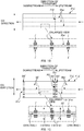
- a disposable diaper 1' shown in the schematic perspective view of FIG. 1A is a conventional example of an absorbent article that absorbs excrement such as urine.
- This diaper 1' includes a first sheet-like member 31' and a second sheet-like member 41' that have been given stretchability in the lateral direction by elastic members 35' attached thereto.
- the diaper 1' also includes side-seal sections SS' in end portions 31e' (41e') in the lateral direction, and in the side-seal sections SS', the two sheet-like members are welded together overlaid in the thickness direction, which intersects the lateral direction and the vertical direction.
- the elastic members 35' are normally attached to the first sheet-like member 31' with use of an adhesive.
- an adhesive there is a risk that hardening of the adhesive at the outer circumferential surfaces of the elastic members 35' will impair the elasticity (i.e., stretchability) of the elastic members 35' and impair the softness of the first sheet-like member 31'.
- consideration has been given to the attachment of the elastic members 35' to the first sheet-like member 31' without using an adhesive, and the following is one example of such a method disclosed in PTL 1.
- EP3111900 A1 discloses a manufacturing method for an absorbent article in which leg elastic members are placed so that a part of each leg elastic member overlaps with an adhesion area on a bandlike member.
- EP3127517 A1 relates to a method for producing an underpants-type disposable diaper where stretchable regions are formed by applying an adhesive in vertical striped patterns to two layers and fixing elastic members therebetween: pleats are formed, extending vertically and straight.
- FIGS. 1B and 1C are schematic plan views for describing the aforementioned method.
- the elastic members 35' contract in the direction of transport compared to FIG. 1B as will be described later, the direction-of-transport gaps between joining portions j' that are adjacent in the direction of transport are actually smaller than the direction-of-transport gaps between the joining portions j' in the enlarged view in FIG. 1B .
- these gaps in FIG. 1C are shown at the same size as in FIG. 1B .
- FIGS. 6A and 6B that will be described later. The following describes the aforementioned method with reference to FIGS. 1B and 1C .
- the first-sheet-like-member continuous body 31a' is continuous in the direction of transport, and is transported with its direction of transport conforming to the lateral direction of the diaper 1'.
- Elastic-member continuous bodies 35a' are continuous in the direction of transport, and are inserted between a pair of mutually-opposing facing surfaces of the first-sheet-like-member continuous body 31a' with stretching in the direction of transport.
- a plurality of joining portions j' for joining the pair of facing surfaces are formed at intervals in the direction of transport.
- the joining portions j' are formed at positions on two sides of the elastic-member continuous body 35a' with respect to a CD direction that intersects the direction of transport.
- the first-sheet-like-member continuous body 31a' is cut at cutting target positions PC' of the continuous body 31a' in the direction of transport, thus forming cutform-shaped first sheet-like members 31' having the elastic members 35' attached thereto as shown in FIG. 1C .
- the elastic members 35' that have been cut contract in the direction of transport and attempt to expand in the CD direction.
- the expansion of the elastic members 35' in the CD direction is restricted by the pairs of joining portions j' located on the two sides in the CD direction, and therefore the elastic members 35' are substantially sandwiched and pressed in the CD direction by the joining portions j'.
- the elastic members 35' are attached to the first sheet-like member 31'.
- each first sheet-like member 31a' is provided with the two side-seal sections SS' in the respective lateral end portions 31e'; at this time the lateral direction conforms to the direction of transport.
- the present invention was achieved in light of the foregoing conventional problems, and an aspect of the present invention is to suppress the formation of a portion that does not have stretchability in a region of a first sheet-like member that is laterally inward of side-seal sections, the first sheet-like member pertaining to an absorbent article.
- the present invention provides the method for manufacturing an absorbent article of independent claim 1, the device for manufacturing an absorbent article of independent claim 12 and the absorbent article of independent claim 13.
- the dependent claims specify preferred but optional features.
- the joining portions mentioned in accordance with the present invention are welded portions.
- a main aspect of the present invention for achieving the above-described aspect is a method for manufacturing an absorbent article, the absorbent article including a first sheet-like member, a second sheet-like member, an elastic member, and a side-seal section, the elastic member being attached to the first sheet-like member, the first sheet-like member having been given a stretchability in a lateral direction by the elastic member, the side-seal section being provided in each lateral end portion of the absorbent article, the first sheet-like member and the second sheet-like member being overlaid in a thickness direction and welded together in the side-seal section, the thickness direction being a direction that intersects the lateral direction, the method including:
- an absorbent article having a lateral direction, a vertical direction, and a front-rear direction that are orthogonal to each other,
- the joining portions are formed so that a portion of at least one of the joining portions is overlapped with at least a portion of the side-seal section.
- the elastic members are attached to the first sheet-like member by being sandwiched and pressed between the joining portions. Accordingly, it is possible to suppress the case where a portion not having stretchability is formed in a region of the first sheet-like member that is inward of the side-seal sections in the lateral direction, which is the direction of transport.
- At least one of the plurality of joining portions is provided at a position between the side-seal section and the cutting target position in the direction of transport.
- At least joining portion is provided at the position between the side-seal section and the cutting target position in the direction of transport. Accordingly, the elastic member is attached to the first sheet-like member by being sandwiched and pressed between not only the above-described overlapping-joining portions, but also the aforementioned joining portion. This makes it possible to more reliably suppress the case where a portion not having stretchability is formed in a region of the first sheet-like member that is inward of the side-seal sections in the lateral direction, which is the direction of transport.
- At least one of the joining portions is provided straddling the cutting target position in the direction of transport. Accordingly, the elastic member is attached to the first sheet-like member by being sandwiched and pressed between not only the above-described overlapping-joining portions, but also the aforementioned joining portion. This makes it possible to more reliably suppress the case where a portion not having stretchability is formed in a region of the first sheet-like member that is inward of the side-seal sections in the lateral direction, which is the direction of transport.
- the joining portions are provided for each of the elastic-member continuous bodies, and that at least one of the plurality of elastic-member continuous bodies and the joining portions provided for the at least one elastic-member continuous body are provided on a one side in the CD direction with respect to a portion of the side-seal section that is farthest located on the one side in the CD direction.
- the joining portions provided in correspondence with the at least one elastic-member continuous body are provided on the one side in the CD direction with respect to the portion of the side-seal section that is farthest located on the one side in the CD direction. Accordingly, it is possible to suppress the case where a large portion in which the pair of facing surfaces of the first sheet-like member are not joined to each other is formed in a CD-direction end portion. Accordingly, it is possible to suppress the problem that the pair of facing surfaces separate over a wide range due to such an unjoined portion.
- a portion in which the one-side joining portion is provided is a portion that protrudes to the one side in the CD direction with respect to the second sheet-like member.
- the one-side joining portion is provided in a portion of the first sheet-like member that protrudes to the one side in the CD direction with respect to the second sheet-like member. Accordingly, even in the portion of the first sheet-like member that protrudes in the CD direction, it is possible to suppress the case where a large portion in which the pair of facing surfaces are not joined to each other is formed. Accordingly, it is possible to suppress the problem that the pair of facing surfaces separate over a wide range due to such an unjoined portion.
- the adhesive is not provided in the portion where the side-seal section is to be formed. Accordingly, it is possible to suppress a problem that can occur if the adhesive is provided in such portion, that is to say the problem of a reduction in welding strength in the side-seal section caused by a component in the adhesive.
- the second elastic member and the second joining portions are provided in the second sheet-like member. Accordingly, stretchability in the lateral direction can be given to not only the first sheet-like member but also the second sheet-like member.
- the joining portions are formed so that a portion of at least one of the second joining portions is overlapped with the side-seal section.
- the elastic members are attached to the second sheet-like member by being sandwiched and pressed between the second joining portions. Accordingly, it is possible to suppress the case where a portion not having stretchability is formed in a region of the second sheet-like member that is inward of the side-seal sections in the lateral direction, which is the direction of transport.
- At least one of the plurality of first overlapping-joining portions is shifted in the direction of transport or the CD direction with respect to the second overlapping-joining portion that is closest in the CD direction to the at least one first overlapping-joining portion. Accordingly, it is possible to suppress a problem that can occur if the first overlapping-joining portion and the second overlapping-joining portion are completely overlapped, that is to say the problem that the stiffness of the side-seal section of the absorbent article will vary greatly, which is likely to cause the person touching that portion to feel discomfort.
- the upstream end of the overlapping-joining portion in the direction of transport is located downstream with respect to the upstream end of the downstream side-seal section in the direction of transport. Accordingly, after cutting is performed at the cutting target position, an end portion of the elastic member moves downstream in the direction of transport due to direction-of-transport contraction of the elastic member, and it is possible to suppress the case where the end portion of the elastic string protrudes upstream, in the direction of transport, of the downstream side-seal section. This therefore makes it possible to achieve a favorable appearance for the downstream side-seal section.
- the upstream end of the overlapping-joining portion in the direction of transport is located downstream in the direction of transport with respect to a central position of the downstream side-seal section in the direction of transport.
- the upstream end of the overlapping-joining portion in the direction of transport is located downstream with respect to the central position of the downstream side-seal section in the direction of transport. Accordingly, after cutting is performed at the cutting target position, an end portion of the elastic member moves downstream in the direction of transport due to direction-of-transport contraction of the elastic member, and it is possible to suppress the case where the end portion of the elastic string protrudes upstream, in the direction of transport, of the downstream side-seal section. This therefore makes it possible to achieve a favorable appearance for the downstream side-seal section.
- the size of the formation pitch of the joining portions is smaller than the direction-of-transport size of the side-seal section. Accordingly, at least one of the joining portions can be overlapped with the side-seal section.
- an absorbent article having a lateral direction, a vertical direction, and a front-rear direction that are orthogonal to each other,
- the joining portions are formed so that a portion of at least one of the joining portions is overlapped with at least a portion of the side-seal section.
- the elastic members are attached to the first sheet-like member by being sandwiched and pressed between the joining portions. Accordingly, it is possible to suppress the case where a portion not having stretchability is formed in a region of the first sheet-like member that is inward of the side-seal sections in the lateral direction, which is the direction of transport.
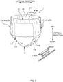
- FIG. 2 is a schematic perspective view of a three piece-type of diaper 1 as one example of the diaper 1.
- the diaper 1 In the underpants-shaped state before being worn as shown in FIG. 2 , the diaper 1 has a vertical direction, a lateral direction that is orthogonal to the vertical direction, and a "front-back direction" that is orthogonal to the vertical direction and the lateral direction.
- the vertical direction often conforms to the up-down direction when the diaper 1 is worn. For this reason, hereinafter, the vertical direction will also be called the up-down direction.
- the upper side corresponds to the waist side of the wearer
- the lower side corresponds to the crotch side of the wearer.
- the front side corresponds to the stomach side of the wearer
- the back side corresponds to the back side of the wearer.
- one side corresponds to the left side of the wearer, and the other side corresponds to the right side of the wearer.
- the diaper 1 includes: a front band member 31 that extends in the lateral direction; a back band member 41 that extends along the lateral direction, is located on the back side of the front band member 31, and is for forming a waist opening BH on the upper side in the vertical direction along with the front band member 31; and an absorbent main body 10 that is a crotch portion provided between the front band member 31 and the back band member 41.
- the absorbent main body 10 is arranged at a position protruding farther downward in the vertical direction than the front band member 31 and the back band member 41 do.
- lateral end portions 31e of the front band member 31 and corresponding lateral end portions 41e of the back band member 41 are joined in side-seal sections SS. Accordingly, the front band member 31 and the back band member 41 respectively form leg openings LH on two lateral sides on the lower side along with the absorbent main body 10.
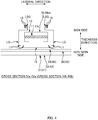
- FIG. 3 is a schematic plan view of the diaper 1 in an unfolded state as viewed from the wearer's skin side.
- FIG. 4 includes a cross-sectional view along IVa-IVa and a cross-sectional view along IVb-IVb in FIG. 3 .
- the unfolded state is a state in which the aforementioned side-seal sections SS on the two lateral sides of the diaper 1 in the underpants-shaped state shown in FIG. 2 are detached such that the front band member 31 and the back band member 41 separate from each other and the diaper 1 is opened in the vertical direction, and thus the diaper 1 is unfolded in a plan view.
- the diaper 1 is shown in a virtual state in which there is no stretchability in the members that constitute the diaper 1.
- the diaper 1 is provided with elastic members 17, 18, 35, and 45 for the purpose of giving stretchability to the diaper 1 in this example, in the aforementioned unfolded state, the diaper 1 is shown in a virtual state in which the elastic members 17, 18, 35, and 45 have no stretchability (contractive force) whatsoever.
- the diaper 1 In the unfolded state, the diaper 1 has a longitudinal direction, a lateral direction, and a thickness direction (direction passing through the paper plane in FIG. 3 ) as three directions that are orthogonal to each other.
- the longitudinal direction conforms the previously described vertical direction.
- one side corresponds to the stomach side, and the other side corresponds to the back side.
- the outer side in the longitudinal direction corresponds to the upper side in the vertical direction
- the inner side in the longitudinal direction corresponds to the lower side in the vertical direction.
- the vertical direction and the vertical direction are directions that resemble each other in this way, for the sake of convenience hereinafter, the vertical direction will sometimes be used in place of the longitudinal direction in the unfolded state as well.
- the lateral direction is synonymous with the lateral direction in the previously described underpants-shaped state.
- one side corresponds to the skin side that comes into contact with the wearer's body, and the other side corresponds to the opposite non-skin side. Note that the thickness direction conforms to the previously described front-back direction.
- the front band member 31 is arranged extending in the lateral direction
- the back band member 41 is arranged extending in the lateral direction at a position that is separated from the front band member 31 by a predetermined gap in the longitudinal direction.
- the absorbent main body 10 spans along the longitudinal direction between the front band member 31 and the back band member 41, and longitudinal end portions 10ea and 10eb of the absorbent main body 10 are respectively joined and fixed to the closest band members 31 and 41, thus forming a substantially H-like outer shape in a plan view.
- the diaper 1 in this state is folded one time at a folding position that is at a predetermined longitudinal position CL1 of the absorbent main body 10 (a longitudinal central position CL1 of the diaper 1), and the lateral end portions 31e and 41e of the band members 31 and 41, which face each other in the folded state, are joined to each other in the previously described side-seal sections SS. Accordingly, the band members 31 and 41 become connected to each other in a ring shape, thus obtaining the diaper 1 in the underpants-shaped state in which the waist opening BH and the pair of leg openings LH are formed as shown in FIG. 2 .
- the absorbent main body 10 has an approximately rectangular shape in a plan view in the unfolded state shown in FIG. 3 .
- the longitudinal direction of the absorbent main body 10 conforms to the longitudinal direction of the diaper 1.
- the absorbent main body 10 includes: an absorbent body 11; a liquid-permeable top sheet 13 that covers the absorbent body 11 from the skin side and forms the skin-side surface of the absorbent main body 10; and a liquid-impermeable back sheet 15 that covers the absorbent body 11 from the non-skin side and forms the non-skin side of the absorbent main body 10.
- the absorbent body 11 has a liquid-absorbent absorbent core 11c, and a core-wrapping sheet (not shown) that covers the outer circumferential surface of the core 11c.
- the absorbent core 11c is a molded body that is made of a predetermined liquid absorbent material such as pulp fiber or superabsorbent polymer, and is approximately hourglass-shaped in a plan view, as one example of a predetermined shape.
- the core-wrapping sheet can be made of a liquid-permeable sheet such as tissue paper or nonwoven fabric, but the core-wrapping sheet is not required to be provided.
- the absorbent core 11c is not limited in any way to having the aforementioned approximately hourglass-like shape in a plan view, and may have another shape.
- the top sheet 13 is a liquid-permeable soft sheet made of nonwoven fabric or the like.
- the back sheet 15 is also a liquid-impermeable soft sheet.
- One example of the back sheet 15 is a double-layer structure laminate sheet 15 including: a liquid-impermeable leak-proof sheet made of a polyethylene film (PE) or a polypropylene film; and an exterior sheet that is made of nonwoven fabric and is affixed to the non-skin side of the leak-proof sheet.
- PE polyethylene film
- polypropylene film polypropylene film
- At least the back sheet 15 is a sheet having a planar size according to which it projects from the absorbent body 11 in the longitudinal direction and the lateral direction.
- Leg gathers LG that stretch and contract in the longitudinal direction are formed in the portions that protrude in the lateral direction.
- elastic strings 17 that serve as elastic members and extend in the longitudinal direction are fixed in the protruding portions in a state of being stretched in the longitudinal direction, thus forming the stretchable leg gathers LG in these portions.
- the absorbent main body 10 has barrier cuffs LSG as leak-proof wall portions in the lateral end portions for the purpose of preventing lateral leakage.
- barrier cuffs LSG as leak-proof wall portions in the lateral end portions for the purpose of preventing lateral leakage.
- a configurations are provided in which elastic strings 18 serving as elastic members 18 and extending in the longitudinal direction are attached, in a state of being stretched in the longitudinal direction, to sheet-like portions that will form the barrier cuffs LSG.
- the front band member 31 is a sheet-like member that is approximately rectangular in a plan view and is constituted by two nonwoven fabric sheets 32 and 33. Specifically, as shown in FIG. 4 , the two nonwoven fabric sheets 32 and 33 are overlaid on each other in the thickness direction. And, the pair of facing surfaces that face each other are joined to each other by welded portions j (corresponding to joining portions) that are arranged discretely in the vertical direction (longitudinal direction) and the lateral direction as shown in later-described FIG. 5 . As shown in FIG. 3 , the front band member 31 is arranged so as to protrude out from the absorbent main body 10 on the two lateral sides, and is overlaid on and joined to the non-skin side of the front end portion 10ea of the absorbent main body 10.
- spunbond nonwoven fabric is used for both of the two nonwoven fabric sheets 32 and 33 pertaining to the front band member 31.
- nonwoven fabric such as SMS (spunbond/meltblown/spunbond) nonwoven fabric.
- standalone fibers made of polypropylene (PP), which is a representative example of a thermoplastic may be used as the constituent fibers of the nonwoven fabric, but there is no limitation whatsoever to this.
- PP polypropylene
- standalone fibers made of another thermoplastic resin such as polyethylene (PE) may be used, and composite fibers that have a sheath/core structure and are made of PE and PP or the like may be used. Note that the same also applies to the back band member 41 that will be described hereinafter.
- the back band member 41 is also a sheet-like member that is approximately rectangular in a plan view and is constituted by two nonwoven fabric sheets 42 and 43. Specifically, as shown in FIG. 4 , the two nonwoven fabric sheets 42 and 43 are overlaid on each other in the thickness direction, and, similarly to the front band member 31 shown in FIG. 5 , the pair of facing surfaces that face each other are joined to each other by welded portions j (corresponding to second joining portions) that are arranged discretely in the vertical direction (longitudinal direction) and the lateral direction. As shown in FIG. 3 , the back band member 41 is arranged so as to protrude out from the absorbent main body 10 on the two lateral sides, and is overlaid on and joined to the non-skin side of the back end portion 10eb of the absorbent main body 10.
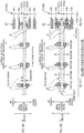
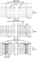
- FIG. 5 is a schematic plan view of the front band member 31 in the unfolded state as viewed from the non-skin side.
- the previously-described side-seal section SS is provided in each of the two end portions 31e (41e) in the lateral direction of the front band member 31 (41).
- the side-seal sections SS have welded portions SSk, SSk... that are the same shape as each other and are arranged side-by-side along a straight line that extends in the vertical direction.
- the nonwoven fabric sheet 33 of the front band member 31 and the nonwoven fabric sheet 43 of the back band member 41 are welded to each other, and a pair of mutually-opposing facing surfaces of the two nonwoven fabric sheets 32 and 33 pertaining to the front band member 31 are welded to each other, and furthermore, a pair of mutually-opposing facing surfaces of the two nonwoven fabric sheets 42 and 43 pertaining to the back band member 41 are welded to each other.
- a plurality of elastic strings 35, 35... (45, 45%) which are elastic members (second elastic members) that extend in the lateral direction, are inserted side-by-side in the vertical direction between the pair of opposing facing surfaces of the two nonwoven fabric sheets 32 and 33 (42 and 43) of the front band member 31 (41).
- the elastic strings 35, 35... (45, 45%) are attached to the nonwoven fabric sheets 32 and 33 (42 and 43) with use of the welded portions j, j... that were mentioned above.
- the front band member 31 (41) is given stretchability in the lateral direction.
- the previously mentioned welded portions j, j... not only have a function of joining the pair of facing surfaces of the two nonwoven fabrics 32 and 33 (42 and 43) to each other, but also have a function of attaching the elastic strings 35 (45) to the two nonwoven fabric sheets 32 and 33 (42 and 43).
- FIGS. 6A and 6B are schematic enlarged views of a portion VI in FIG. 5 , and are for illustrating the latter function of the welded portions j, that is to say the function of attaching the elastic strings 35 (45) .
- the welded portions j, j... are provided for each of the elastic strings 35 (45) that extend in the lateral direction.
- the welded portions j are formed in pairs of portions on respective sides of the corresponding elastic string 35 in the vertical direction, that is to say, each pair of welded portions j that are side-by-side in the vertical direction make up welded portion pair jP.
- These welded portion pairs jP are formed side-by-side in the lateral direction spacing between welded portion pairs jP that are adjacent in the lateral direction. Also, as shown in FIG.
- the pair of welded portions j that form each welded portion pair jP are separated by a gap Dj in the vertical direction, and the size of this gap Dj is set the same as or somewhat larger than a vertical size D35t (D45t) of the elastic strings 35 (45) in a state of being stretched to a target stretch factor in the lateral direction.
- D35t vertical size of the elastic strings 35 (45) in a state of being stretched to a target stretch factor in the lateral direction.
- the elastic strings 35 (45) contract in the lateral direction and expand in the vertical direction, and here, based on the size relationship described above, the expansion of the elastic strings 35 (45) in the vertical direction is restricted by the pairs of welded portions j. Accordingly, the elastic strings 35 (45) are substantially sandwiched and pressed in the vertical direction by the pairs of welded portions j, and as a result, the elastic strings 35 (45) are attached in the front band member 31 (41).
- the aforementioned target stretch factor is selected from the range of 1.5 to 4.0, for example.
- the front band member 31 (41) includes a region R31 (R41) that is laterally inward of the welded portions SSk of the side-seal sections SS, and this region is a portion that comes into contact with the stomach side of the wearer's torso. For this reason, it is preferable that the inward region R31 (R41) has stretchability over the entire range in the lateral direction.
- the overlapping-welded portion jr is provided for all of the elastic strings 35, 35... (45, 45%) that are provided in the front band member 31 (41) in the example in FIG. 5 , there is no limitation whatsoever to this.
- the overlapping-welded portion jr is provided for at least one of the elastic strings, desirably one-third or more of the elastic strings, more desirably half or more of the elastic strings, and even more desirably two-thirds or more of the elastic strings, it is possible to suppress the above-described problems for at least the elastic strings 35 (45) that are provided with the overlapping-welded portion jr.
- elastic strings 35 (45) not provided with the overlapping-welded portion jr may exist among the elastic strings 35 (45) pertaining to the front band member 31 (41).
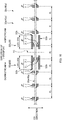
- FIG. 8 is a schematic plan view showing a partial perspective view of the manufacturing of the diaper 1 in the manufacturing line.
- FIGS. 9A, 9B, and 9C are respectively schematic enlarged views of portions A, B, and C in FIG. 8 .
- the continuous sheets 42a and 43a pertaining to the back band member 41 would originally be visible instead of the continuous sheets 32a and 33a pertaining to the front band member 31, but for the sake of convenience in the description, it is assumed that the continuous sheets 32a and 33a pertaining to the front band member 31 are visible in the following description. Note that the same applies to later-described FIGS. 11A to 14 as well.
- the two nonwoven fabric sheets 32 and 33 (corresponding to first sheet-like members) pertaining to the front band member 31 are transported in the form of continuous sheets 32a and 33a (corresponding to a first-sheet-like-member continuous body) that are continuous in the direction of transport, and likewise, the two nonwoven fabric sheets 42 and 43 (corresponding to second sheet-like members) pertaining to the back band member 41 are transported in the form of continuous sheets 42a and 43a (corresponding to a second-sheet-like-member continuous body) that are continuous in the direction of transport.
- the continuous sheets 32a, 33a, 42a, and 43a pass through processing positions PK1 to PK5 that are set in the direction of transport, and the continuous sheets 32a, 33a, 42a, and 43a are subjected to processing processes that correspond to the processing positions PK1, PK2, and so on.
- the direction that is orthogonal to both the thickness direction and the direction of transport of the continuous sheets 32a, 33a, 42a, and 43a is defined as "CD direction", and in this example, the continuous sheets 32a, 33a, 42a, and 43a (i.e., the two continuous sheets 32a and 33a pertaining to the front band member 31 and the two continuous sheets 42a and 43a pertaining to the back band member 41) are transported side-by-side in the CD direction. Note that there is no limitation whatsoever to this.
- the above-described processing positions namely the first to fifth processing positions PK1 to PK5, are set side-by-side in this order from upstream to downstream in the direction of transport.
- the processes that are performed on the continuous sheets 32a and 33a pertaining to the front band member 31 are substantially the same as those performed on the two continuous sheets 42a and 43a pertaining to the back band member 41.
- the front band member 31 and the back band member 41 will not be distinguished from each other when the same content applies hereinafter.
- the term “band member 31 (41)” will simply be used, or the term “the two continuous sheets 32a and 33a (42a and 43a)” will simply be used.
- the reference signs that immediately follow the terms are the reference signs pertaining to the front band member 31, and the subsequent reference signs in the parentheses are the reference signs pertaining to the back band member 41.
- the two continuous sheets 32a and 33a (42a and 43a) pertaining to the band member 31 (41) are transported in a so-called lateral flow.
- the two continuous sheets 32a and 33a (42a and 43a) are transported such that the direction corresponding to the lateral direction of the diaper 1 conforms to the direction of transport.
- boundary positions PBL between two diapers 1 that are adjacent in the lateral direction are virtually set at a product pitch P1 in the direction of transport.
- the boundary position PBL is a cutting target position PC at which the two continuous sheets 32a and 33a (42a and 43a) are cut to produce a single-cut diaper 1.
- the two continuous sheets 32a and 33a (42a and 43a) pertaining to the band member 31 (41) are transported by appropriate transporting devices (not shown) such as a belt conveyor and transporting rollers. Accordingly, unless particularly stated otherwise, it is assumed that the two continuous sheets 32a and 33a (42a and 43a) are transported in the direction of transport by such transporting devices.
- the belt conveyor includes a normal belt conveyor that has an endless belt that is driven to rotate as a transporting surface, and a suction belt conveyor that has a function for suction to the outer circumferential surface of an endless belt.
- the stretchability of the continuous sheets 32a, 33a, 42a, and 43a is much smaller than the stretchability of the elastic strings 35 and 45, to the extent that such stretchability can be ignored.
- the continuous sheets 32a, 33a, 42a, and 43a are then transported from the first processing position PK1 to the fifth processing position PK5 while being stretched in the direction of transport.
- the two continuous sheets 32a and 33a (42a and 43a) pertaining to the band member 31 (41) pass the first processing position PK1. While passing, as shown in FIGS. 8 and 9A , the two continuous sheets 32a and 33a (42a and 43a) are overlaid on each other in the thickness direction. At this time, the elastic-string continuous bodies 35a, 35a...
- the elastic-string continuous bodies 35a (45a) are arranged on the pair of facing surfaces by a transporting device (corresponding to an arranging device) such as transporting rollers (not shown).
- the previously described welded portions j, j... are formed as joining portions (second joining portions) in the two continuous sheets 32a and 33a (42a and 43a), and thus the pair of facing surfaces of the two continuous sheets 32a and 33a (42a and 43a) are joined to each other by the welded portions j, j... (corresponding to a joining-portion forming step and a second-joining-portion forming step).
- the welded portions j are formed in pairs, on two sides in the CD direction of the elastic-string continuous bodies 35a (45a). Specifically, as shown in FIG. 9B , two welded portions j that are side-by-side on respective sides in the CD direction of each continuous body 35a (45a) form a welded portion pair jP. These welded portion pairs jP are formed side-by-side in the direction of transport spacing between welded portion pairs jP that are adjacent in the direction of transport.
- the two welded portions j that form each welded portion pair jP are separated by the gap Dj in the CD direction, and here, the size of the gap Dj is the same as or somewhat larger than the size D35t (D45t) in the CD direction of the elastic-string continuous bodies 35a (45a) which are located at the first processing position PK1 and which are in a state of being stretched to the target stretch factor in the direction of transport.
- the elastic-string continuous bodies 35a (45a) are cut at the later-described fifth processing position PK5 thus relaxing the stretched state of the elastic strings 35 (45), as shown in FIG. 6B , the elastic strings 35 (45) contract in the direction of transport and attempt to expand in the CD direction. But, the elastic strings 35 (45) are sandwiched and pressed in the CD direction between the pair of welded portions j, and thus the elastic strings 35 (45) are attached to the two nonwoven fabric sheets 32 and 33 (42 and 43) of the band member 31 (41).
- the overlapping-welded portions jr (j) are reliably provided by performing the following, for example. Specifically, as shown in FIG. 10 , first, several welded portions j, j... are provided at a predetermined formation pitch Pj in the direction of transport so as to span and extend beyond the position of the side-seal section SS and the cutting target position PC in the direction of transport. In this example, the welded portions j, j... are provided at the formation pitch Pj over the entire length in the direction of transport.
- the size of the former formation pitch Pj is smaller than the size LSS of the latter side-seal section SS.
- the size of the formation pitch Pj is smaller than a direction-of-transport size LSSk of the welded portions SSk of the side-seal section SS.
- the side-seal section SS is constituted by a plurality of welded portions SSk, SSk... that have the same shape and are side-by-side along one straight line that extends in the CD direction.
- the side-seal section SS has an end SSeu located upstream and an end SSed located downstream in the direction of transport, and the welded portions SSk has an end SSkeu located upstream and an end SSked located downstream in the direction of transport.
- the positions of the upstream and downstream ends SSeu and SSed of the side-seal section SS respectively match the positions of the upstream and downstream ends SSkeu and SSked of the welded portions SSk. Accordingly, the direction-of-transport size LSS of the side-seal section SS and the direction-of-transport size LSSk of the welded portion SSk are the same value as each other as shown in FIG. 10 . Accordingly, the foregoing comparison with the formation pitch Pj can be performed with the size LSSk of the welded portion SSk instead of the size LSS of the side-seal section SS.
- the upstream end SSkeu of the welded portion SSk located most upstream in the direction of transport in the side-seal section SS is the upstream end SSeu of the side-seal section SS
- the downstream end SSked in the welded portion SSk located most downstream in the direction of transport in the side-seal section SS is the downstream end SSed of the side-seal section SS.
- the size LSS of the side-seal section SS is the direction-of-transport distance between the upstream end SSkeu of the most upstream welded portion SSk and the downstream end SSked of the most downstream welded portion SSk.
- the central position CSS in the direction of transport of the side-seal section SS refers to the midpoint between the upstream end SSkeu of the most upstream welded portion SSk and the downstream end SSked of the most downstream welded portion SSk.
- the upstream end SSeu, the downstream end SSed, and the central position CSS of this side-seal section SS are defined in a similar manner for cases that will be described later with reference to FIGS. 11A and 11B .
- the welded portions j can be formed using a heat sealing device or an ultrasonic sealing device (corresponding to a joining-portion forming device) that is not shown, for example.
- a heat sealing device has a pair of rolls that are heated while rotating in the direction of transport, for example.
- One of the rolls is a heat emboss roll that has protrusion portions corresponding to the welded portions j on the outer circumferential surface, and the other roll is an anvil roll that receives the protrusion portions with a smooth outer circumferential surface.
- an ultrasonic sealing device has a horn that has a vibrating surface that vibrates in a normal direction, and an anvil roll that rotates in the direction of transport, for example.
- the anvil roll has protrusion portions that correspond to the welded portions j on the outer circumferential surface in order to receive the vibrating surface.
- the two continuous sheets 32a and 33a pertaining to the front band member 31 and the two continuous sheets 42a and 43a pertaining to the back band member 41 all pass the second processing position PK2.
- the single-cut absorbent main body 10 produced in a separate step (not shown) is fixed in a state of spanning between the two continuous sheets 32a and 33a pertaining to the front band member 31 and the two continuous sheets 42a and 43a pertaining to the back band member 41, thus forming the approximately ladder-shaped diaper continuous body 1hs in which approximately H-shaped unfolded diapers 1h, 1h... are continuous with each other.
- the absorbent main body 10 is fixed using a rotating drum device that is not shown, for example.
- the rotating drum device has a rotating drum that rotates in the direction of transport, and the rotating drum has a plurality of holding portions that detachably hold the absorbent main body 10 to the outer circumferential surface, for example.
- the approximately ladder-shaped diaper continuous body 1hs passes the third processing position PK3.
- the absorbent main body 10 is folded one time at a predetermined position CL1 in the CD direction, and therefore the two continuous sheets 32a and 33a pertaining to the front band member 31 and the two continuous sheets 42a and 43a pertaining to the back band member 41 are overlaid on each other in the thickness direction (corresponding to an overlaying step).
- the folding can be performed using a fold guiding device (corresponding to an overlaying device) that is not shown, for example.
- the fold guiding device has a guide plate and guide rollers that are arranged at predetermined positions in the direction of transport, for example.
- the guide plate and the guide rollers guide the approximately ladder-shaped diaper continuous body 1hs passing at the arrangement position so as to be folded one time.
- the folded diaper continuous body 1hsb passes the fourth processing position PK4.
- the continuous sheets 32a and 33a and 42a and 43a which are overlaid in the thickness direction are welded at positions on two sides of the cutting target position PC in the direction of transport so as to form a pair of side-seal sections SS (corresponding to a side-seal-section forming step), thus fixing the diaper continuous body 1hsb in the folded state.
- This consequently produces an underpants-shaped diaper continuous body Is in which a plurality of underpants-shaped diapers 1, 1... are connected in the lateral direction.
- the side-seal sections SS have a plurality of welded portions SSk, SSk... that are side-by-side in the CD direction (vertical direction).
- the welded portions SSk weld together the continuous sheet 33a of the front band member 31 and the continuous sheet 43a of the back band member 41, weld together the pair of facing surfaces of the continuous sheets 32a and 33a of the front band member 31, and weld together the pair of facing surfaces of the continuous sheets 42a and 43a of the back band member 41 ( FIG. 8 ) .
- the planar shape of the welded portions SSk is a laterally elongated rectangular shape that is longer in the lateral direction, which is the CD direction, than in the vertical direction, which is the direction of transport. Note that there is no limitation whatsoever to this. For example, it may have a parallelogram shape or oval shape, or may have another shape. Also, in this example, the longitudinal direction of the welded portions SSk conforms to the lateral direction, which is the direction of transport, but there is no limitation whatsoever to this. In other words, the longitudinal direction of the welded portions SSk may conform to the vertical direction, which is the CD direction, or may conform to a direction that intersects both the lateral direction and the vertical direction.
- the adhesive is not provided in the portions where the side-seal sections SS are to be formed, that is to say the portions where the welded portions SSk, SSk... are to be formed. Accordingly, it is possible to suppress a problem that can occur if the adhesive is provided in such portions, that is to say the problem of a reduction in welding strength in the side-seal sections SS caused by a component in the adhesive.
- the side-seal sections SS can be formed using a heat sealing device or an ultrasonic sealing device (corresponding to a side-seal-section forming device) that is not shown, for example.
- a heat sealing device has a pair of rolls that are heated while rotating in the direction of transport, for example.
- One of the rolls is a heat emboss roll that has protrusion portions corresponding to the welded portions SSk of the side-seal sections SS on the outer circumferential surface
- the other roll is an anvil roll that receives the protrusion portions with a smooth outer circumferential surface.
- an ultrasonic sealing device has a horn that has a vibrating surface that vibrates in a normal direction, and an anvil roll that rotates in the direction of transport, for example.
- the anvil roll has protrusion portions that correspond to the welded portions SSk on the outer circumferential surface in order to receive the vibrating surface.
- the underpants-shaped diaper continuous body Is passes the fifth processing position PK5.
- the continuous body Is is cut at the cutting target position PC that is located between a pair of side-seal sections SS (corresponding to a cutting step), thus obtaining the diaper 1.
- the two continuous sheets 32a and 33a (42a and 43a) pertaining to the front band member 31 and the back band member 41 and the elastic-string continuous bodies 35a, 35a... (45a, 45a...) are cut at the cutting target position PC. Due to the corresponding relaxation of the stretched state of the elastic strings 35 (45), the elastic strings 35 (45) are sandwiched and pressed by the pairs of welded portions j in the welded portion pairs jP and are thus attached to the band members 31 and 41, and this is the same as in the description of the first processing position PK1.
- This cutting can be performed using a cutter device (corresponding to a cutting device) that is not shown, for example.
- a cutter device has a pair of rolls that rotate in the direction of transport, for example.
- One of the rolls is a cutter roll that has a cutter blade on the outer circumferential surface, and the other roll is an anvil roll having an outer circumferential surface that receives the cutter blade.
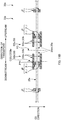
- FIGS. 11A and 11B are schematic views for specifically describing an example of a state where overlapping-welded portions jr and the side-seal section SS are overlapped. Note that both of these figures are schematic plan views of a portion in the vicinity of the cutting target position PC in the underpants-shaped diaper continuous body Is immediately before being cut at the fifth processing position PK5, as viewed in the thickness direction.
- the two end portions 35e are formed in each elastic string 35 on respective sides of the cutting target position PC in the direction of transport.
- the elastic-string continuous body 35a has portions 35ae that are to be the end portions 35e of the elastic string 35, and these portions 35ae are located on respective sides of the cutting target position PC in the direction of transport.
- the overlapping-welded portions jr ultimately attach the end portions 35e to the pair of facing surfaces of the continuous sheets 32a and 33a.
- the overlapping-welded portions jr are formed on respective sides of the cutting target position PC in the direction of transport.
- the two overlapping-welded portions jr on the respective sides are formed so as to be approximately in line symmetry with each other with respect to the cutting target position PC.
- the two side-seal sections SS formed on the respective sides of the cutting target position PC are formed so as to be approximately in line symmetry with each other with respect to the cutting target position PC.
- the side-seal section SS located downstream in the direction of transport will also be referred to as a “downstream side-seal section SSd", and the side-seal section SS located upstream will also be referred to as an "upstream side-seal section SSu”.
- the welded portions j that are located closest to the cutting target position PC are overlapping-welded portions jr.
- upstream ends jreu of the overlapping-welded portions jr in the direction of transport are located downstream in the direction of transport with respect to the upstream end SSdeu of the downstream side-seal section SSd in the direction of transport.
- the overlapping-welded portions jr are located downstream in the direction of transport with respect to upstream ends SSkreu of welded portions SSkr which are the welded portions SSk, SSk... of the downstream side-seal section SSd and which are overlapped with the overlapping-welded portions jr.
- an end portion 35e of the elastic string 35 moves downstream in the direction of transport due to direction-of-transport contraction of the elastic string 35, and it is possible to suppress the case where the end portion 35e of the elastic string 35 protrudes upstream, in the direction of transport, of the position of the downstream side-seal section SSd. This therefore makes it possible to achieve a favorable appearance for the downstream side-seal section SSd.
- the welded portions j located closest to the cutting target position PC are not required to be overlapping-welded portions jr, and this similarly applies to the later-described example in FIG. 11B as well.
- the above-described effects can be suitably achieved as long as the overlapping-welded portions jr pertaining to at least one elastic-string continuous body 35a are in the above-described positional relationship. Accordingly, there is no need for the overlapping-welded portions jr, jr... pertaining to all of the elastic-string continuous bodies 35a, 35a... in FIG. 9C to be in the above-described positional relationship.
- the overlapping-welded portions jr, jr... pertaining to one-third or more, half or more, or two-thirds or more of all of the elastic-string continuous bodies 35a, 35a may be in the above-described positional relationship, and this similarly applies to the later-described example in FIG. 11B as well.
- the arrangement of the overlapping-welded portions jr and the side-seal section SS in the positional relationship shown in FIG. 11A can be realized by setting the arrangement pattern of protrusion portions on the outer circumferential surface of a roll of the previously-described heat sealing device or ultrasonic sealing device provided at the first processing position PK1, and setting the arrangement pattern of protrusion portions on the outer circumferential surface of a roll of the previously-described heat sealing device or ultrasonic sealing device provided at the fourth processing position PK4, for example.
- the welded portions j that are located closest to the cutting target position PC are overlapping-welded portions jr.
- upstream ends jreu of the overlapping-welded portions jr in the direction of transport are located downstream in the direction of transport with respect to the central position CSS of the downstream side-seal section SSd in the direction of transport.
- the overlapping-welded portions jr are located downstream in the direction of transport with respect to the central positions CSSkr of welded portions SSkr which are the welded portions SSk, SSk... of the downstream side-seal section SSd and which are overlapped with the overlapping-welded portions jr. This therefore makes it possible to more reliably suppress the above-described protrusion of the end portion 35e of the elastic string 35.
- At least one welded portion j (j1) is provided at a position between the side-seal section SS and the cutting target position PC in the direction of transport as shown in FIG. 12A .
- the elastic string 35 is attached to the two nonwoven fabric sheets 32 and 33 pertaining to the front band member 31 due to being sandwiched and pressed by not only the above-described overlapping-welded portions jr but also by two welded portions j1.
- At least one welded portion j (j2) other than a overlapping-welded portion jr is provided straddling the cutting target position PC in the direction of transport as shown in FIG. 12B . Even with this configuration, it is possible to achieve a suppress effect similar to that described above.
- the elastic-string continuous bodies 35a, 35a... are arranged side-by-side in the CD direction, and a pair of the previously described welded portions j are provided in correspondence with each of the elastic-string continuous bodies 35a as shown in FIG. 9B .
- the following configuration is desirable: concerning a welded portion SSk1 which is a farthest-located-on-one-side-in-CD-direction one of the welded portions SSk, SSk...
- this welded portion SSk1 corresponding to the "portion of the side-seal section that is farthest located on the one side in the CD direction"
- at least one of the elastic-string continuous bodies 35a, 35a... is provided on the one side in the CD direction with respect to the welded portion SSk1; and the pair of welded portions j provided in correspondence with that elastic-string continuous body 35a are provided on the one side with respect to the welded portion SSk1.
- these welded portions j will also be called “one-side welded portions j3 (corresponding to one-side joining portions)", and in this example in FIG. 13 , the one side in the CD direction corresponds to the upper side in the vertical direction of the diaper 1.
- the one-side welded portions j3 are formed in a portion that is to form the waist opening BH in the two continuous sheets 32a and 33a pertaining to the front band member 31.
- the one-side welded portions j3 make it possible to suppress the case where large portions in which the pair of facing surfaces of the two nonwoven fabric sheets 32 and 33 pertaining to the front band member 31 are not joined to each other are formed in the CD-direction end portions after the cutting step in the fifth processing position PK5. Accordingly, it is possible to suppress the problem that the pair of facing surfaces separate over a wide range due to such unjoined portions.
- the two continuous sheets 32a and 33a pertaining to the front band member 31 and the two continuous sheets 42a and 43a pertaining to the back band member 41 are overlaid in the thickness direction such that, by design, the vertical upper end portion 31eu of the front band member 31 and the vertical upper end portion 41eu of the back band member 41 in FIG. 2 match each other in the vertical direction.
- the folding precision in this folding processing there is produced, as shown in FIG.
- a CD-direction shift between a pertaining-front-band-member end portion 31aeu and a pertaining-back-band-member end portion 41aeu corresponds to the upper end portion 31eu in the for-front-band-member continuous sheets 32a and 33a
- the end portion 41aeu corresponds to the upper end portion 41eu in the for-back-band-member continuous sheets 42a and 43a.
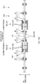
- FIG. 15 is a schematic illustrative view of a positional relationship between overlapping-welded portions jr of the continuous sheets 32a and 33a pertaining to the front band member 31 and overlapping-welded portions jr of the continuous sheets 42a and 43a pertaining to the back band member 41.
- FIG. 15 is a schematic plan view of the underpants-shaped-disposable-diaper continuous body Is that is transported between the fourth processing position PK4 and the fifth processing position PK5 in the manufacturing line ( FIG. 8 ). More specifically, it is a schematic view of the cutting target position PC and the vicinity thereof in the continuous body Is as viewed from the front band member 31 side in the thickness direction.
- the elastic-string continuous bodies 35a of the front band member 31 and the elastic-string continuous bodies 45a of the back band member 41 are overlapped in the thickness direction at several locations in the CD direction, whereas at several other locations, there are only the elastic-string continuous bodies 35a of the front band member 31, and at still other locations there are only the elastic-string continuous bodies 45a of the back band member 41 are provided.
- first overlapping-welded portions jr1 corresponding to first overlapping-joining portions
- second overlapping-welded portions jr2 corresponding to second overlapping-joining portions
- all of the first overlapping-welded portions jr1, jr1... are shifted in the direction of transport with respect to the second overlapping-welded portions jr2 that are closest thereto. Also, several of the first overlapping-welded portions jr1, jr1... are shifted in the CD direction as well with respect to the corresponding second overlapping-welded portions jr2, and several of those first overlapping-welded portions jr1 are shifted not being overlapped at all with the corresponding second overlapping-welded portions jr2.
- first overlapping-welded portion jr1 may be shifted in the direction of transport and not in the CD direction, or conversely, may be shifted in the CD direction and not in the direction of transport, and such first overlapping-welded portions jr1 are also shown in the example in FIG. 15 .
- the above-described CD-direction shifting of the first overlapping-welded portions jr1 can be realized by adjusting in the CD direction the folding position at which the approximately ladder-shaped diaper continuous body 1hs is folded at the third processing position PK3; the folding position is a predetermined position in the CD direction.
- adjusting the predetermined position in the CD direction causes to adjust the relative positions in the CD direction of the for-back-band-member-41 continuous sheets 42a and 43a relative to the for-front-band-member-31 continuous sheets 32a and 33a, and this makes it possible to reliably achieve the aforementioned positional shifting.
- the above-described direction-of-transport shifting of the first overlapping-welded portion jr1 can be realized by adjusting the rotation-direction phases of the following rolls: the first one is a roll of the previously described heat sealing device or ultrasonic sealing device arranged at the first processing position PK1, and has protrusions; and the second one is a roll of the previously described heat sealing device or ultrasonic sealing device arranged at the fourth processing position PK4, and has protrusions.
- the welded portion j is illustrated as an example of the joining portion (second joining portion) that joins together the mutually-opposing pair of facing surfaces of the two nonwoven fabric sheets 32 and 33 (42 and 43) as shown in FIG. 5 , but there is no limitation whatsoever to this.
- the joining portion (second joining portion) may be formed using an adhesive, and in this case, the adhesive is selectively applied, on at least one of the two facing surfaces, to a target formation position at which the joining portion (second joining portion) is to be formed.
- first-sheet-like-member continuous body second-sheet-like-member continuous body
- first-sheet-like-member continuous body second-sheet-like-member continuous body
- the first-sheet-like-member continuous body may be constituted by one continuous sheet.
- the pair of facing surfaces are formed by folding one continuous sheet at a predetermined position in the CD direction, and then inserting the elastic-string continuous bodies 35a (45a) between the pair of facing surfaces.
- the elastic strings 35 (45) are illustrated as examples of elastic members (second elastic members), and the elastic-string continuous bodies 35a (45a) are illustrated as examples of the elastic-member continuous bodies (continuous bodies of the second elastic member), but spandex and the like are other specific examples of such elastic strings 35 (45), and LYCRA (registered trademark) is an example of such a product.
- the elastic strings 35 (45) can have a fiber density of 400 dtex to 1,000 dtex, for example.
- rubber strips may be used as the elastic members (second elastic members), and rubber strip continuous bodies may be used as the elastic-member continuous bodies (second elastic-member continuous bodies).
- all of the elastic strings 35, 35... provided in the front band member 31 are arranged so as to be continuous over substantially the entire length in the lateral direction, but there is no limitation whatsoever to this.
- several of the elastic strings 35, 35... may be discontinuous at a central position in the lateral direction for example. Note that the same applies to the elastic strings 45, 45... of the back band member 41 as well.
- the three-piece type of disposable diaper 1 is illustrated as an example of the absorbent article, but there is no limitation whatsoever to this.
- the method of the present invention may be used when attaching elastic members such as elastic strings to a sheet-like member for use in a two-piece type of disposable diaper.
- a two-piece type disposable diaper is a type of diaper that has a first component and a second component: the first component is an exterior sheet having a two-layer structure and including a front portion, a crotch portion, and a back portion; and the second component is the absorbent main body 10 fixed to the skin-side surface of the exterior sheet.
- the welded portion j having an approximately square shape in a plan view is illustrated as an example of the joining portion (second joining portion) as shown in FIG. 6 , but the shape of the welded portion j is not limited in any way to this.
- a circular shape may be applied, or an elongated shape having a longitudinal direction, such as a rectangular or oval shape, may be used.
- the longitudinal direction may conform to the direction of transport (lateral direction), may conform to the CD direction (vertical direction), or may conform to a direction that intersects both the direction of transport and the CD direction.
- the welded portions j, j... (including the overlapping-welded portions jr) are provided in a so-called ladder-like arrangement that is defined in the lateral direction and the vertical direction (longitudinal direction).
- the welded portions j, j... are provided at intersections between virtual lines extending in the lateral direction and virtual lines extending in the vertical direction, but there is no limitation whatsoever to this.
- the welded portions j, j... may be provided in a so-called staggered arrangement by being providing at positions that are shifted in the lateral direction from the aforementioned intersections.
- the welded portions j, j... are arranged side-by-side in the vertical direction in FIG. 5 , there is no limitation whatsoever to this.
- the welded portions j, j... may be arranged side-by-side in a diagonal direction that intersects both the vertical direction and the lateral direction.
- the two overlapping-welded portions jr that form the overlapping-welded portion pair jrP are provided at the same position as each in the lateral direction (direction of transport), but there is no limitation whatsoever to this.
- the positions of the two overlapping-welded portions jr may be shifted from each other in the lateral direction (direction of transport) as long as the elastic string 35 (45) can be sandwiched and pressed.
- the virtual straight line on which the two overlapping-welded portions jr are to be aligned is not required to extend in the CD direction, and may be inclined from the CD direction at a predetermined angle other than 90°. Note that this similarly applies to the welded portions j, j... other than the overlapping-welded portions jr as well.
- a welded portion j is not provided between two welded portion pairs jP that are adjacent in the vertical direction (CD direction), but there is no limitation whatsoever to this.
- one or more welded portions j may be provided between two welded portion pairs jP. Note that such a welded portion j does not contribute to attachment of the elastic strings 35 (45) to the nonwoven fabric sheets 32 and 33 (42 and 43), and only contributes to the joining of the nonwoven fabric sheets 32 and 33 (42 and 43) to each other.
- the elastic strings 35 (45) attempt to contract in the direction of transport and expand in the CD direction due to the cutting performed in the cutting step at the fifth processing position PK5, but are sandwiched and pressed in the CD direction between pairs of welded portions j, and the elastic strings 35 (45) are thus attached to the two nonwoven fabric sheets 32 and 33 (42 and 43).
- the elastic strings 35 (45) attempt to contract in the direction of transport and expand in the CD direction due to the cutting performed in the cutting step at the fifth processing position PK5, but are sandwiched and pressed in the CD direction between pairs of welded portions j, and the elastic strings 35 (45) are thus attached to the two nonwoven fabric sheets 32 and 33 (42 and 43).
- the elastic strings 35 (45) attempt to contract in the direction of transport and expand in the CD direction due to the cutting performed in the cutting step at the fifth processing position PK5, but are sandwiched and pressed in the CD direction between pairs of welded portions j, and the elastic strings 35 (45) are thus attached to the two nonwoven fabric sheets 32 and 33
- a configuration is possible in which, at a stage before the cutting step, the elastic-string continuous bodies 35a (45a), which have been inserted between the pair of facing surfaces of the continuous sheets 32a and 33a (42a and 43a) pertaining to the two nonwoven fabric sheets 32 and 33 (42 and 43), are allowed to relax from the stretched state such that the continuous bodies 35a (45a) contract in the direction of transport, and thus the continuous bodies 35a (45a) are sandwiched and pressed in the CD direction between the pair of welded portions j.
- the underpants-shaped diaper continuous body Is may be cut in the cutting step, thus producing the diaper 1.
- the nonwoven fabric sheets 42 and 43 that are produced by cutting the two continuous sheets 42a and 43a also include the elastic strings 45 (the second elastic members) attached thereto by being sandwiched and pressed between pair of welded portions j (second joining portions).
- the elastic strings 45 may be attached by not only being sandwiched and pressed between pairs of welded portions j, but also by the adhesive.
- the overlapping-welded portions jr are not required to be provided, that is to say, the second elastic members such as the elastic strings 45 can also be omitted from the nonwoven fabric sheets 42 and 43.
Description
- The present invention relates to an absorbent article such as a disposable diaper and a method and a device for manufacturing the absorbent article.
- A disposable diaper 1' shown in the schematic perspective view of
FIG. 1A is a conventional example of an absorbent article that absorbs excrement such as urine. This diaper 1' includes a first sheet-like member 31' and a second sheet-like member 41' that have been given stretchability in the lateral direction by elastic members 35' attached thereto. And, the diaper 1' also includes side-seal sections SS' inend portions 31e' (41e') in the lateral direction, and in the side-seal sections SS', the two sheet-like members are welded together overlaid in the thickness direction, which intersects the lateral direction and the vertical direction. - The elastic members 35' are normally attached to the first sheet-like member 31' with use of an adhesive. However, when the elastic members 35' are attached with use of an adhesive, there is a risk that hardening of the adhesive at the outer circumferential surfaces of the elastic members 35' will impair the elasticity (i.e., stretchability) of the elastic members 35' and impair the softness of the first sheet-like member 31'. For this reason, in recent years, consideration has been given to the attachment of the elastic members 35' to the first sheet-like member 31' without using an adhesive, and the following is one example of such a method disclosed in
PTL 1. - [PTL 1] Japanese Unexamined Patent Application Publication (Translation of PCT Application) No.
2001-504899 -
EP3111900 A1 discloses a manufacturing method for an absorbent article in which leg elastic members are placed so that a part of each leg elastic member overlaps with an adhesion area on a bandlike member. -
EP3127517 A1 relates to a method for producing an underpants-type disposable diaper where stretchable regions are formed by applying an adhesive in vertical striped patterns to two layers and fixing elastic members therebetween: pleats are formed, extending vertically and straight. -
FIGS. 1B and 1C are schematic plan views for describing the aforementioned method. In the enlarged view ofFIG. 1C , the elastic members 35' contract in the direction of transport compared toFIG. 1B as will be described later, the direction-of-transport gaps between joining portions j' that are adjacent in the direction of transport are actually smaller than the direction-of-transport gaps between the joining portions j' in the enlarged view inFIG. 1B . But, for the sake of convenience, these gaps inFIG. 1C are shown at the same size as inFIG. 1B . The same follows for the enlarged views inFIGS. 6A and 6B that will be described later. The following describes the aforementioned method with reference toFIGS. 1B and 1C . - First, as shown in
FIG. 1B , the first-sheet-like-membercontinuous body 31a' is continuous in the direction of transport, and is transported with its direction of transport conforming to the lateral direction of the diaper 1'. Elastic-membercontinuous bodies 35a' are continuous in the direction of transport, and are inserted between a pair of mutually-opposing facing surfaces of the first-sheet-like-membercontinuous body 31a' with stretching in the direction of transport. - Next, a plurality of joining portions j' for joining the pair of facing surfaces are formed at intervals in the direction of transport. At this time, the joining portions j' are formed at positions on two sides of the elastic-member
continuous body 35a' with respect to a CD direction that intersects the direction of transport. - Subsequently, the first-sheet-like-member
continuous body 31a' is cut at cutting target positions PC' of thecontinuous body 31a' in the direction of transport, thus forming cutform-shaped first sheet-like members 31' having the elastic members 35' attached thereto as shown inFIG. 1C . Due to this cutting, the elastic members 35' that have been cut contract in the direction of transport and attempt to expand in the CD direction. But here, the expansion of the elastic members 35' in the CD direction is restricted by the pairs of joining portions j' located on the two sides in the CD direction, and therefore the elastic members 35' are substantially sandwiched and pressed in the CD direction by the joining portions j'. As a result, the elastic members 35' are attached to the first sheet-like member 31'. - Also, as shown in
FIG. 1C , when cutting is performed at the cutting target positions PC', the second-sheet-like-membercontinuous body 41a' has already been overlaid on the first-sheet-like-membercontinuous body 31a', and the side-seal sections SS' have already been formed on the two sides of the cutting target positions PC' in the direction of transport. Accordingly, after the first sheet-like members 31a' are produced by the cutting at the cutting target positions PC', each first sheet-like member 31a' is provided with the two side-seal sections SS' in the respectivelateral end portions 31e'; at this time the lateral direction conforms to the direction of transport. - Also, in the diaper 1' in the state shown in
FIG. 1A , a region R31' of the first sheet-like member 31' that is laterally inward of the side-seal sections SS' comes into contact with the stomach side of the wearer's torso. For this reason, this inward region R31' needs to be given with stretchability in the lateral direction. In the case where the joining portions j' are not provided in the side-seal sections SS' and laterally outside of the side-seal sections SS' as shown in the partial enlarged view inFIG. 1A , when the cutting at the cutting target positions PC' (FIG. 1C ) causes the elastic members 35' to contract in the lateral direction (the direction of transport), there is a risk thatend portions 35e' of the elastic members 35' will not stop at positions laterally outside the inward region R31', but rather will move into the inward region R31' as shown in the partial enlarged view ofFIG. 1A . If this happens, some portions in lateral end portions R31e' of the inward region R31' will lose stretchability, which originally should be given to the portions . Thus, the diaper 1' will become an unsuitable product in terms of stretchability. - The present invention was achieved in light of the foregoing conventional problems, and an aspect of the present invention is to suppress the formation of a portion that does not have stretchability in a region of a first sheet-like member that is laterally inward of side-seal sections, the first sheet-like member pertaining to an absorbent article.
- The present invention provides the method for manufacturing an absorbent article of
independent claim 1, the device for manufacturing an absorbent article ofindependent claim 12 and the absorbent article ofindependent claim 13. The dependent claims specify preferred but optional features. - The joining portions mentioned in accordance with the present invention are welded portions.
- A main aspect of the present invention for achieving the above-described aspect is a method for manufacturing an absorbent article,
the absorbent article including a first sheet-like member, a second sheet-like member, an elastic member, and a side-seal section,
the elastic member being attached to the first sheet-like member,
the first sheet-like member having been given a stretchability in a lateral direction by the elastic member,
the side-seal section being provided in each lateral end portion of the absorbent article,
the first sheet-like member and the second sheet-like member being overlaid in a thickness direction and welded together in the side-seal section,
the thickness direction being a direction that intersects the lateral direction,
the method including: - an arranging step of arranging a plurality of elastic-member continuous bodies between a pair of mutually-opposing facing surfaces of a first-sheet-like-member continuous body that is being transported,
- a direction of transport of the first-sheet-like-member continuous body conforming to the lateral direction,
- the plurality of elastic-member continuous bodies being continuous in the direction of transport,
- the first-sheet-like-member continuous body being continuous in the direction of transport,
- the plurality of elastic-member continuous bodies being in a stretched state in the direction of transport and being placed side-by-side with spacing in a CD direction,
- the CD direction intersecting the direction of transport and the thickness direction;
- a joining-portion forming step of forming a plurality of joining portions spacing in the direction of transport and the CD direction,
- the joining portions joining the pair of facing surfaces of the first-sheet-like-member continuous body to each other,
- the joining-portion forming step including forming the plurality of joining portions on two sides of the elastic-member continuous bodies in the CD direction while maintaining the elastic-member continuous bodies in a state of being stretched in the direction of transport,
- the joining portions being formed so that, by direction-of-transport contraction and CD-direction expansion of the elastic member after a cutting step, the elastic member is sandwiched and pressed in the CD direction by the joining portions on the two sides, being attached to the first sheet-like member,
- the joining portions being formed so that a portion of at least one of the joining portions is overlapped with at least a portion of the side-seal section in a view of the first-sheet-like-member continuous body in the thickness direction;
- an overlaying step of overlaying, in the thickness direction, a second-sheet-like-member continuous body on the first-sheet-like-member continuous body in which the joining portions have been formed,
the second-sheet-like-member continuous body being continuous in the direction of transport; - a side-seal-section forming step of forming the side-seal section on each of two sides of each of cutting target positions in the direction of transport,
- the cutting target positions being set at a predetermined pitch in the direction of transport,
- the first-sheet-like-member continuous body and the second-sheet-like-member continuous body that have been overlaid on each other in the thickness direction being welded together in the side-seal section; and
- the cutting step of producing the absorbent article that has the elastic member, the first sheet-like member, and the second sheet-like member,
the cutting step being performed after the side-seal-section forming step and by cutting the first-sheet-like-member continuous body, the elastic-member continuous bodies, and the second-sheet-like-member continuous body at each of the cutting target positions. - Further, a device for manufacturing an absorbent article,
- the absorbent article including a first sheet-like member, a second sheet-like member, an elastic member, and a side-seal section,
- the elastic member being attached to the first sheet-like member,
- the first sheet-like member having been given a stretchability in a lateral direction by the elastic member,
- the side-seal section being provided in each lateral end portion of the absorbent article,
- the first sheet-like member and the second sheet-like member being overlaid in a thickness direction and welded together in the side-seal section,
- the thickness direction being a direction that intersects the lateral direction,
- the device including:
- an arranging device configured to arrange a plurality of elastic-member continuous bodies between a pair of mutually-opposing facing surfaces of a first-sheet-like-member continuous body that is being transported,
- a direction of transport of the first-sheet-like-member continuous body conforming to the lateral direction,
- the plurality of elastic-member continuous bodies being continuous in the direction of transport,
- the first-sheet-like-member continuous body being continuous in the direction of transport,
- the plurality of elastic-member continuous bodies being in a stretched state in the direction of transport and being placed side-by-side with spacing in a CD direction,
- the CD direction intersecting the direction of transport and the thickness direction;
- a joining-portion forming device configured to form a plurality of joining portions spaced in the direction of transport and the CD direction,
- the joining portions joining the pair of facing surfaces of the first-sheet-like-member continuous body to each other,
- the joining-portion forming device forming the plurality of joining portions on two sides of the elastic-member continuous bodies in the CD direction while maintaining the elastic-member continuous bodies in a state of being stretched in the direction of transport,
- the forming is performed so that, by direction-of-transport contraction and CD-direction expansion of the elastic member at a position downstream in the direction of transport with respect to a cutting device, the elastic member is sandwiched and pressed in the CD direction by the joining portions on the two sides, being attached to the first sheet-like member,
- the forming is performed so that a portion of at least one of the joining portions is overlapped with at least a portion of the side-seal section in a view of the first-sheet-like-member continuous body in the thickness direction;
- an overlaying device configured to overlay, in the thickness direction, a second-sheet-like-member continuous body on the first-sheet-like-member continuous body in which the joining portions have been formed,
the second-sheet-like-member continuous body being continuous in the direction of transport; - a side-seal-section forming device configured to form the side-seal section on each of two sides of each of cutting target positions in the direction of transport,
- the cutting target positions being set at a predetermined pitch in the direction of transport,
- the first-sheet-like-member continuous body and the second-sheet-like-member continuous body that have been overlaid on each other in the thickness direction being welded together in the side-seal section; and
- the cutting device configured to produce the absorbent article that has the elastic member, the first sheet-like member, and the second sheet-like member,
at a position downstream in the direction of transport with respect to the side-seal-section forming device, the cutting device cutting the first-sheet-like-member continuous body, the elastic-member continuous bodies, and the second-sheet-like-member continuous body at each of the cutting target positions.
- an arranging device configured to arrange a plurality of elastic-member continuous bodies between a pair of mutually-opposing facing surfaces of a first-sheet-like-member continuous body that is being transported,
- Further, an absorbent article having a lateral direction, a vertical direction, and a front-rear direction that are orthogonal to each other,
- the absorbent article including:
- a first sheet-like member;
- a second sheet-like member;
- a plurality of elastic members that are inserted along the lateral direction between a pair of mutually-opposing facing surfaces of the first sheet-like member, and that are arranged with spacing in the vertical direction;
- a plurality of joining portions that are for joining together the pair of facing surfaces and that are arranged with spacing in the lateral direction and in the vertical direction,
the joining portions being formed on two sides of the elastic members in the vertical direction so that the elastic members are sandwiched and pressed between the joining portions on the two sides; and - a side-seal section that is provided in each lateral end portion,
- a portion of at least one of the joining portions being overlapped with at least a portion of the side-seal section in a view of the first sheet-like member in the front-rear direction
- the first sheet-like member and the second sheet-like member being overlaid in the front-rear direction and welded in the side-seal section.
- Features of the present invention other than the above will become clear by reading the description of the present specification with reference to the accompanying drawings.
- According to the present invention, it is possible to suppress the formation of a portion that does not have stretchability in a region of a first sheet-like member pertaining to an absorbent article that is laterally inward of side-seal sections.
-
-
FIG. 1A is a schematic perspective view of a disposable diaper 1' as one example of an absorbent article. -
FIG. 1B is a diagram illustrating a method for attaching elastic members 35' to a first sheet-like member 31' pertaining to the diaper 1' without using an adhesive. -
FIG. 1C is a diagram illustrating the above method. -
FIG. 2 is a schematic perspective view of a three piece-type ofdiaper 1 as one example of an absorbent article of an embodiment. -
FIG. 3 is a schematic plan view of thediaper 1 in an unfolded state as viewed from a wearer's skin side. -
FIG. 4 includes a cross-sectional view along IVa-IVa and a cross-sectional view along IVb-IVb inFIG. 3 . -
FIG. 5 is a schematic plan view of afront band member 31 in the unfolded state as viewed from the non-skin side. -
FIGS. 6A and 6B are illustrative views of an elastic string 35 (45) attachment function exhibited by welded portions j. -
FIG. 7 is a schematic plan view of a front band member 31 (41) not having overlapping-welded portions jr as a comparative example, as viewed from the non-skin side. -
FIG. 8 is a schematic plan view showing a partial perspective view of how thediaper 1 is manufactured in a manufacturing line. -
FIGS. 9A, 9B, and 9C are respectively schematic enlarged views of portions A, B, and C inFIG. 8 . -
FIG. 10 is a schematic view showing an enlarged view of an example in which the size of a formation pitch Pj in the direction of transport of welded portions j, j... is set smaller than a size LSS in the direction of transport of a side-seal section SS. -
FIG. 11A is a schematic view for describing an example of a state where overlapping-welded portions jr and the side-seal section SS are overlapped. -
FIG. 11B is a schematic view of the same. -
FIG. 12A is a schematic view of a case where welded portions j (j1) other than the overlapping-welded portions jr are provided at positions between the side-seal section SS and a cutting target position PC in the direction of transport. -
FIG. 12B is a schematic view of a case where welded portions j (j2) other than the overlapping-welded portions jr are provided so as to span the cutting target position PC in the direction of transport. -
FIG. 13 is a schematic view of a case where welded portions j (j3) are provided on one side in a CD direction of a welded portion SSk1 that is located farthest on the one side among welded portions SSk, SSk... in the side-seal section SS. -
FIG. 14 is a schematic view of a case where end portions 31aeu in the CD direction of twocontinuous sheets front band member 31 protrude to the one side in the CD direction beyond end portions 41aeu in the CD direction of twocontinuous sheets back band member 41 inFIG. 13 . -
FIG. 15 is a schematic illustrative view of a positional relationship between overlapping-welded portions jr of thecontinuous sheets front band member 31 and overlapping-welded portions jr of thecontinuous sheets back band member 41. - At least the following matters will become clear with the description of this specification and the attached drawings.
- A method for manufacturing an absorbent article,
- the absorbent article including a first sheet-like member, a second sheet-like member, an elastic member, and a side-seal section,
- the elastic member being attached to the first sheet-like member,
- the first sheet-like member having been given a stretchability in a lateral direction by the elastic member,
- the side-seal section being provided in each lateral end portion of the absorbent article,
- the first sheet-like member and the second sheet-like member being overlaid in a thickness direction and welded together in the side-seal section,
- the thickness direction being a direction that intersects the lateral direction,
- the method including:
- an arranging step of arranging a plurality of elastic-member continuous bodies between a pair of mutually-opposing facing surfaces of a first-sheet-like-member continuous body that is being transported,
- a direction of transport of the first-sheet-like-member continuous body conforming to the lateral direction,
- the plurality of elastic-member continuous bodies being continuous in the direction of transport,
- the first-sheet-like-member continuous body being continuous in the direction of transport,
- the plurality of elastic-member continuous bodies being in a stretched state in the direction of transport and being placed side-by-side with spacing in a CD direction,
- the CD direction intersecting the direction of transport and the thickness direction;
- a joining-portion forming step of forming a plurality of joining portions spaced in the direction of transport and the CD direction,
- the joining portions joining the pair of facing surfaces of the first-sheet-like-member continuous body to each other,
- the joining-portion forming step including forming the plurality of joining portions on two sides of the elastic-member continuous bodies in the CD direction while maintaining the elastic-member continuous bodies in a state of being stretched in the direction of transport,
- the joining portions being formed so that, by direction-of-transport contraction and CD-direction expansion of the elastic member after a cutting step, the elastic member is sandwiched and pressed in the CD direction by the joining portions on the two sides, being attached to the first sheet-like member,
- the joining portions being formed so that a portion of at least one of the joining portions is overlapped with at least a portion of the side-seal section in a view of the first-sheet-like-member continuous body in the thickness direction;
- an overlaying step of overlaying, in the thickness direction, a second-sheet-like-member continuous body on the first-sheet-like-member continuous body in which the joining portions have been formed,
the second-sheet-like-member continuous body being continuous in the direction of transport; - a side-seal-section forming step of forming the side-seal section on each of two sides of each of cutting target positions in the direction of transport,
- the cutting target positions being set at a predetermined pitch in the direction of transport,
- the first-sheet-like-member continuous body and the second-sheet-like-member continuous body that have been overlaid on each other in the thickness direction being welded together in the side-seal section; and
- the cutting step of producing the absorbent article that has the elastic member, the first sheet-like member, and the second sheet-like member,
the cutting step being performed after the side-seal-section forming step and by cutting the first-sheet-like-member continuous body, the elastic-member continuous bodies, and the second-sheet-like-member continuous body at each of the cutting target positions.
- an arranging step of arranging a plurality of elastic-member continuous bodies between a pair of mutually-opposing facing surfaces of a first-sheet-like-member continuous body that is being transported,
- According to this method for manufacturing an absorbent article, the joining portions are formed so that a portion of at least one of the joining portions is overlapped with at least a portion of the side-seal section. Also, the elastic members are attached to the first sheet-like member by being sandwiched and pressed between the joining portions. Accordingly, it is possible to suppress the case where a portion not having stretchability is formed in a region of the first sheet-like member that is inward of the side-seal sections in the lateral direction, which is the direction of transport.
- In such a method for manufacturing an absorbent article, it is desirable that
at least one of the plurality of joining portions is provided at a position between the side-seal section and the cutting target position in the direction of transport. - According to this method for manufacturing an absorbent article, at least joining portion is provided at the position between the side-seal section and the cutting target position in the direction of transport. Accordingly, the elastic member is attached to the first sheet-like member by being sandwiched and pressed between not only the above-described overlapping-joining portions, but also the aforementioned joining portion. This makes it possible to more reliably suppress the case where a portion not having stretchability is formed in a region of the first sheet-like member that is inward of the side-seal sections in the lateral direction, which is the direction of transport.
- In such a method for manufacturing an absorbent article, it is desirable that
when the at least one joining portion that is overlapped with the side-seal section is defined as an overlapping-joining portion,
at least one of the joining portions other than the overlapping-joining portion is provided straddling the cutting target position in the direction of transport. - According to this method for manufacturing an absorbent article, at least one of the joining portions is provided straddling the cutting target position in the direction of transport. Accordingly, the elastic member is attached to the first sheet-like member by being sandwiched and pressed between not only the above-described overlapping-joining portions, but also the aforementioned joining portion. This makes it possible to more reliably suppress the case where a portion not having stretchability is formed in a region of the first sheet-like member that is inward of the side-seal sections in the lateral direction, which is the direction of transport.
- In such a method for manufacturing an absorbent article, it is desirable
that the joining portions are provided for each of the elastic-member continuous bodies, and
that at least one of the plurality of elastic-member continuous bodies and the joining portions provided for the at least one elastic-member continuous body are provided on a one side in the CD direction with respect to a portion of the side-seal section that is farthest located on the one side in the CD direction. - According to this method for manufacturing an absorbent article, the joining portions provided in correspondence with the at least one elastic-member continuous body are provided on the one side in the CD direction with respect to the portion of the side-seal section that is farthest located on the one side in the CD direction. Accordingly, it is possible to suppress the case where a large portion in which the pair of facing surfaces of the first sheet-like member are not joined to each other is formed in a CD-direction end portion. Accordingly, it is possible to suppress the problem that the pair of facing surfaces separate over a wide range due to such an unjoined portion.
- In such a method for manufacturing an absorbent article, it is desirable that
when the joining portion provided on the one side in the CD direction with respect to the portion of the side-seal section that is farthest located on the one side in the CD direction is defined as a one-side joining portion,
of the first sheet-like member, a portion in which the one-side joining portion is provided is a portion that protrudes to the one side in the CD direction with respect to the second sheet-like member. - According to this method for manufacturing an absorbent article, the one-side joining portion is provided in a portion of the first sheet-like member that protrudes to the one side in the CD direction with respect to the second sheet-like member. Accordingly, even in the portion of the first sheet-like member that protrudes in the CD direction, it is possible to suppress the case where a large portion in which the pair of facing surfaces are not joined to each other is formed. Accordingly, it is possible to suppress the problem that the pair of facing surfaces separate over a wide range due to such an unjoined portion.
- In such a method for manufacturing an absorbent article, it is desirable that
in the first-sheet-like-member continuous body and the second-sheet-like-member continuous body, an adhesive is not provided in a portion where the side-seal section is to be formed. - According to this method for manufacturing an absorbent article, the adhesive is not provided in the portion where the side-seal section is to be formed. Accordingly, it is possible to suppress a problem that can occur if the adhesive is provided in such portion, that is to say the problem of a reduction in welding strength in the side-seal section caused by a component in the adhesive.
- In such a method for manufacturing an absorbent article, it is desirable
- that a second elastic member is attached to the second sheet-like member,
- that the second sheet-like member has been given stretchability in the lateral direction by the second elastic member,
- that the method further comprises:
- a second arranging step of arranging a plurality of second-elastic-member continuous bodies between a pair of mutually-opposing facing surfaces of the second-sheet-like-member continuous body,
- the plurality of second-elastic-member continuous bodies being continuous in the direction of transport,
- the plurality of second-elastic-member continuous bodies being in a stretched state in the direction of transport and being placed side-by-side with spacing in the CD direction; and
- a second-joining-portion forming step of forming a plurality of second joining portions spaced in the direction of transport and the CD direction,
- the second joining portions joining the pair of facing surfaces of the second-sheet-like-member continuous body to each other,
- the second-joining-portion forming step including forming the plurality of second joining portions on two sides of the second-elastic-member continuous bodies in the CD direction while maintaining the second-elastic-member continuous bodies in a state of being stretched in the direction of transport,
- the second joining portions being formed so that, by direction-of-transport contraction and CD-direction expansion of the second elastic member after the cutting step, the second elastic member is sandwiched and pressed in the CD direction by the second joining portions on the two sides, being attached to the second sheet-like member,
- the second joining portions being formed so that a portion of at least one of the second joining portions is overlapped with at least a portion of the side-seal section in a view of the second-sheet-like-member continuous body in the thickness direction,
- that in the overlaying step,
the second-sheet-like-member continuous body in which the second joining portions have been formed is overlaid in the thickness direction on the first-sheet-like-member continuous body in which the joining portions have been formed, and - that in the cutting step,
the absorbent article that has the elastic member, the first sheet-like member, the second elastic member, and the second sheet-like member is produced by cutting the first-sheet-like-member continuous body, the elastic-member continuous bodies, the second-sheet-like-member continuous body, and the second-elastic-member continuous bodies at each of the cutting target positions. - According to this method for manufacturing an absorbent article, the second elastic member and the second joining portions are provided in the second sheet-like member. Accordingly, stretchability in the lateral direction can be given to not only the first sheet-like member but also the second sheet-like member.
- Also, the joining portions are formed so that a portion of at least one of the second joining portions is overlapped with the side-seal section. Also, the elastic members are attached to the second sheet-like member by being sandwiched and pressed between the second joining portions. Accordingly, it is possible to suppress the case where a portion not having stretchability is formed in a region of the second sheet-like member that is inward of the side-seal sections in the lateral direction, which is the direction of transport.
- In such a method for manufacturing an absorbent article, it is desirable that
- when the joining portion that is in the first-sheet-like-member continuous body and that is overlapped with at least a portion of the side-seal section is defined as a first overlapping-joining portion, and
- when the second joining portion that is in the second-sheet-like-member continuous body and that is overlapped with at least a portion of the side-seal section is defined as a second overlapping-joining portion,
in the overlaying step, the first-sheet-like-member continuous body and the second-sheet-like-member continuous body are overlaid such that at least one of a plurality of the first overlapping-joining portions is shifted in the direction of transport or the CD direction with respect to one of a plurality of the second overlapping-joining portions that is closest to the at least one first overlapping-joining portion. - According to this method for manufacturing an absorbent article, at least one of the plurality of first overlapping-joining portions is shifted in the direction of transport or the CD direction with respect to the second overlapping-joining portion that is closest in the CD direction to the at least one first overlapping-joining portion. Accordingly, it is possible to suppress a problem that can occur if the first overlapping-joining portion and the second overlapping-joining portion are completely overlapped, that is to say the problem that the stiffness of the side-seal section of the absorbent article will vary greatly, which is likely to cause the person touching that portion to feel discomfort.
- In such a method for manufacturing an absorbent article, it is desirable that
- when the at least one joining portion that is overlapped with the side-seal section is defined as an overlapping-joining portion, and
- when a downstream one of the side-seal sections formed on two sides of each of the cutting target positions in the direction of transport is defined as a downstream side-seal section,
- the overlapping-joining portion is overlapped with the downstream side-seal section, and
- an upstream end of the overlapping-joining portion in the direction of transport is located downstream in the direction of transport with respect to an upstream end of the downstream side-seal section in the direction of transport.
- According to this method for manufacturing an absorbent article, the upstream end of the overlapping-joining portion in the direction of transport is located downstream with respect to the upstream end of the downstream side-seal section in the direction of transport. Accordingly, after cutting is performed at the cutting target position, an end portion of the elastic member moves downstream in the direction of transport due to direction-of-transport contraction of the elastic member, and it is possible to suppress the case where the end portion of the elastic string protrudes upstream, in the direction of transport, of the downstream side-seal section. This therefore makes it possible to achieve a favorable appearance for the downstream side-seal section.
- In such a method for manufacturing an absorbent article, it is desirable that
the upstream end of the overlapping-joining portion in the direction of transport is located downstream in the direction of transport with respect to a central position of the downstream side-seal section in the direction of transport. - According to this method for manufacturing an absorbent article, the upstream end of the overlapping-joining portion in the direction of transport is located downstream with respect to the central position of the downstream side-seal section in the direction of transport. Accordingly, after cutting is performed at the cutting target position, an end portion of the elastic member moves downstream in the direction of transport due to direction-of-transport contraction of the elastic member, and it is possible to suppress the case where the end portion of the elastic string protrudes upstream, in the direction of transport, of the downstream side-seal section. This therefore makes it possible to achieve a favorable appearance for the downstream side-seal section.
- In such a method for manufacturing an absorbent article, it is desirable
- that at least several of the joining portions are provided at a predetermined formation pitch in the direction of transport so as to span and extend beyond the side-seal section and the cutting target position in the direction of transport, and
- that a size of the formation pitch is smaller than a direction-of-transport size of the side-seal section.
- According to this method for manufacturing an absorbent article, the size of the formation pitch of the joining portions is smaller than the direction-of-transport size of the side-seal section. Accordingly, at least one of the joining portions can be overlapped with the side-seal section.
- Further, a device for manufacturing an absorbent article,
- the absorbent article including a first sheet-like member, a second sheet-like member, an elastic member, and a side-seal section,
- the elastic member being attached to the first sheet-like member,
- the first sheet-like member having been given a stretchability in a lateral direction by the elastic member,
- the side-seal section being provided in each lateral end portion of the absorbent article,
- the first sheet-like member and the second sheet-like member being overlaid in a thickness direction and welded together in the side-seal section,
- the thickness direction being a direction that intersects the lateral direction,
- the device including:
- an arranging device configured to arrange a plurality of elastic-member continuous bodies between a pair of mutually-opposing facing surfaces of a first-sheet-like-member continuous body that is being transported,
- a direction of transport of the first-sheet-like-member continuous body conforming to the lateral direction,
- the plurality of elastic-member continuous bodies being continuous in the direction of transport,
- the first-sheet-like-member continuous body being continuous in the direction of transport,
- the plurality of elastic-member continuous bodies being in a stretched state in the direction of transport and being placed side-by-side with spacing in a CD direction,
- the CD direction intersecting the direction of transport and the thickness direction;
- a joining-portion forming device configured to form a plurality of joining portions spaced in the direction of transport and the CD direction,
- the joining portions joining the pair of facing surfaces of the first-sheet-like-member continuous body to each other,
- the joining-portion forming device forming the plurality of joining portions on two sides of the elastic-member continuous bodies in the CD direction while maintaining the elastic-member continuous bodies in a state of being stretched in the direction of transport,
- the forming is performed so that, by direction-of-transport contraction and CD-direction expansion of the elastic member at a position downstream in the direction of transport with respect to a cutting device, the elastic member is sandwiched and pressed in the CD direction by the joining portions on the two sides, being attached to the first sheet-like member,
- the forming is performed so that a portion of at least one of the joining portions is overlapped with at least a portion of the side-seal section in a view of the first-sheet-like-member continuous body in the thickness direction;
- an overlaying device configured to overlay, in the thickness direction, a second-sheet-like-member continuous body on the first-sheet-like-member continuous body in which the joining portions have been formed,
the second-sheet-like-member continuous body being continuous in the direction of transport; - a side-seal-section forming device configured to form the side-seal section on each of two sides of each of cutting target positions in the direction of transport,
- the cutting target positions being set at a predetermined pitch in the direction of transport,
- the first-sheet-like-member continuous body and the second-sheet-like-member continuous body that have been overlaid on each other in the thickness direction being welded together in the side-seal section; and
- the cutting device configured to produce the absorbent article that has the elastic member, the first sheet-like member, and the second sheet-like member,
- at a position downstream in the direction of transport with respect to the side-seal-section forming device, the cutting device cutting the first-sheet-like-member continuous body, the elastic-member continuous bodies, and the second-sheet-like-member continuous body at each of the cutting target positions.
- an arranging device configured to arrange a plurality of elastic-member continuous bodies between a pair of mutually-opposing facing surfaces of a first-sheet-like-member continuous body that is being transported,
- According to this device for manufacturing an absorbent article, it is possible to achieve actions and effects similar to those in the case of the manufacturing method described above.
- Further, an absorbent article having a lateral direction, a vertical direction, and a front-rear direction that are orthogonal to each other,
- the absorbent article including:
- a first sheet-like member;
- a second sheet-like member;
- a plurality of elastic members that are inserted along the lateral direction between a pair of mutually-opposing facing surfaces of the first sheet-like member, and that are arranged with spacing in the vertical direction;
- a plurality of joining portions that are for joining together the pair of facing surfaces and that are arranged with spacing in the lateral direction and in the vertical direction,
- the joining portions being formed on two sides of the elastic members in the vertical direction so that the elastic members are sandwiched and pressed between the joining portions on the two sides; and
- a side-seal section that is provided in each lateral end portion,
- a portion of at least one of the joining portions being overlapped with at least a portion of the side-seal section in a view of the first sheet-like member in the front-rear direction
- the first sheet-like member and the second sheet-like member being overlaid in the front-rear direction and welded in the side-seal section.
- According to this absorbent article, the joining portions are formed so that a portion of at least one of the joining portions is overlapped with at least a portion of the side-seal section. Also, the elastic members are attached to the first sheet-like member by being sandwiched and pressed between the joining portions. Accordingly, it is possible to suppress the case where a portion not having stretchability is formed in a region of the first sheet-like member that is inward of the side-seal sections in the lateral direction, which is the direction of transport.
- A method and a device for manufacturing an absorbent article according to an embodiment of the present invention are used in, for example, a manufacturing line for a
disposable diaper 1 that is one example of an absorbent article.FIG. 2 is a schematic perspective view of a three piece-type ofdiaper 1 as one example of thediaper 1. - In the underpants-shaped state before being worn as shown in
FIG. 2 , thediaper 1 has a vertical direction, a lateral direction that is orthogonal to the vertical direction, and a "front-back direction" that is orthogonal to the vertical direction and the lateral direction. The vertical direction often conforms to the up-down direction when thediaper 1 is worn. For this reason, hereinafter, the vertical direction will also be called the up-down direction. - Note that with respect to the up-down direction, the upper side corresponds to the waist side of the wearer, and the lower side corresponds to the crotch side of the wearer. Also, with respect to the front-back direction, the front side corresponds to the stomach side of the wearer, and the back side corresponds to the back side of the wearer. Furthermore, with respect to the lateral direction, one side corresponds to the left side of the wearer, and the other side corresponds to the right side of the wearer.
- In the underpants-shaped state shown in
FIG. 2 , thediaper 1 includes: afront band member 31 that extends in the lateral direction; aback band member 41 that extends along the lateral direction, is located on the back side of thefront band member 31, and is for forming a waist opening BH on the upper side in the vertical direction along with thefront band member 31; and an absorbentmain body 10 that is a crotch portion provided between thefront band member 31 and theback band member 41. The absorbentmain body 10 is arranged at a position protruding farther downward in the vertical direction than thefront band member 31 and theback band member 41 do. Also,lateral end portions 31e of thefront band member 31 and correspondinglateral end portions 41e of theback band member 41 are joined in side-seal sections SS. Accordingly, thefront band member 31 and theback band member 41 respectively form leg openings LH on two lateral sides on the lower side along with the absorbentmain body 10. -
FIG. 3 is a schematic plan view of thediaper 1 in an unfolded state as viewed from the wearer's skin side. Also,FIG. 4 includes a cross-sectional view along IVa-IVa and a cross-sectional view along IVb-IVb inFIG. 3 . - Here, the unfolded state is a state in which the aforementioned side-seal sections SS on the two lateral sides of the
diaper 1 in the underpants-shaped state shown inFIG. 2 are detached such that thefront band member 31 and theback band member 41 separate from each other and thediaper 1 is opened in the vertical direction, and thus thediaper 1 is unfolded in a plan view. - Also, in this unfolded state, the
diaper 1 is shown in a virtual state in which there is no stretchability in the members that constitute thediaper 1. For example, although thediaper 1 is provided withelastic members diaper 1 in this example, in the aforementioned unfolded state, thediaper 1 is shown in a virtual state in which theelastic members - In the unfolded state, the
diaper 1 has a longitudinal direction, a lateral direction, and a thickness direction (direction passing through the paper plane inFIG. 3 ) as three directions that are orthogonal to each other. Note that the longitudinal direction conforms the previously described vertical direction. Also, with respect to the longitudinal direction, one side corresponds to the stomach side, and the other side corresponds to the back side. Also, the outer side in the longitudinal direction corresponds to the upper side in the vertical direction, and the inner side in the longitudinal direction corresponds to the lower side in the vertical direction. Given that the longitudinal direction and the vertical direction are directions that resemble each other in this way, for the sake of convenience hereinafter, the vertical direction will sometimes be used in place of the longitudinal direction in the unfolded state as well. Furthermore, the lateral direction is synonymous with the lateral direction in the previously described underpants-shaped state. Moreover, with respect to the thickness direction, one side corresponds to the skin side that comes into contact with the wearer's body, and the other side corresponds to the opposite non-skin side. Note that the thickness direction conforms to the previously described front-back direction. - In the unfolded state shown in
FIG. 3 , thefront band member 31 is arranged extending in the lateral direction, and theback band member 41 is arranged extending in the lateral direction at a position that is separated from thefront band member 31 by a predetermined gap in the longitudinal direction. The absorbentmain body 10 spans along the longitudinal direction between thefront band member 31 and theback band member 41, and longitudinal end portions 10ea and 10eb of the absorbentmain body 10 are respectively joined and fixed to theclosest band members diaper 1 in this state is folded one time at a folding position that is at a predetermined longitudinal position CL1 of the absorbent main body 10 (a longitudinal central position CL1 of the diaper 1), and thelateral end portions band members band members diaper 1 in the underpants-shaped state in which the waist opening BH and the pair of leg openings LH are formed as shown inFIG. 2 . - The absorbent
main body 10 has an approximately rectangular shape in a plan view in the unfolded state shown inFIG. 3 . The longitudinal direction of the absorbentmain body 10 conforms to the longitudinal direction of thediaper 1. Also, as shown inFIG. 4 , the absorbentmain body 10 includes: an absorbent body 11; a liquid-permeable top sheet 13 that covers the absorbent body 11 from the skin side and forms the skin-side surface of the absorbentmain body 10; and a liquid-impermeable back sheet 15 that covers the absorbent body 11 from the non-skin side and forms the non-skin side of the absorbentmain body 10. - The absorbent body 11 has a liquid-absorbent absorbent core 11c, and a core-wrapping sheet (not shown) that covers the outer circumferential surface of the core 11c. The absorbent core 11c is a molded body that is made of a predetermined liquid absorbent material such as pulp fiber or superabsorbent polymer, and is approximately hourglass-shaped in a plan view, as one example of a predetermined shape. The core-wrapping sheet can be made of a liquid-permeable sheet such as tissue paper or nonwoven fabric, but the core-wrapping sheet is not required to be provided. Also, the absorbent core 11c is not limited in any way to having the aforementioned approximately hourglass-like shape in a plan view, and may have another shape.
- The
top sheet 13 is a liquid-permeable soft sheet made of nonwoven fabric or the like. Theback sheet 15 is also a liquid-impermeable soft sheet. One example of theback sheet 15 is a double-layerstructure laminate sheet 15 including: a liquid-impermeable leak-proof sheet made of a polyethylene film (PE) or a polypropylene film; and an exterior sheet that is made of nonwoven fabric and is affixed to the non-skin side of the leak-proof sheet. - As shown in
FIG. 3 , at least theback sheet 15 is a sheet having a planar size according to which it projects from the absorbent body 11 in the longitudinal direction and the lateral direction. Leg gathers LG that stretch and contract in the longitudinal direction are formed in the portions that protrude in the lateral direction. Specifically,elastic strings 17 that serve as elastic members and extend in the longitudinal direction are fixed in the protruding portions in a state of being stretched in the longitudinal direction, thus forming the stretchable leg gathers LG in these portions. - Also, as shown in
FIGS. 3 and4 , the absorbentmain body 10 has barrier cuffs LSG as leak-proof wall portions in the lateral end portions for the purpose of preventing lateral leakage. Specifically, in the lateral end portions of the absorbentmain body 10, a configurations are provided in whichelastic strings 18 serving aselastic members 18 and extending in the longitudinal direction are attached, in a state of being stretched in the longitudinal direction, to sheet-like portions that will form the barrier cuffs LSG. - As shown in
FIG. 3 , thefront band member 31 is a sheet-like member that is approximately rectangular in a plan view and is constituted by twononwoven fabric sheets FIG. 4 , the twononwoven fabric sheets FIG. 5 . As shown inFIG. 3 , thefront band member 31 is arranged so as to protrude out from the absorbentmain body 10 on the two lateral sides, and is overlaid on and joined to the non-skin side of the front end portion 10ea of the absorbentmain body 10. - Also, in this example, spunbond nonwoven fabric is used for both of the two
nonwoven fabric sheets front band member 31. Note that there is no limitation whatsoever to this, and it is possible to use various other types of nonwoven fabric such as SMS (spunbond/meltblown/spunbond) nonwoven fabric. Also, in this example, standalone fibers made of polypropylene (PP), which is a representative example of a thermoplastic, may be used as the constituent fibers of the nonwoven fabric, but there is no limitation whatsoever to this. For example, standalone fibers made of another thermoplastic resin such as polyethylene (PE) may be used, and composite fibers that have a sheath/core structure and are made of PE and PP or the like may be used. Note that the same also applies to theback band member 41 that will be described hereinafter. - Similarly to the
front band member 31, theback band member 41 is also a sheet-like member that is approximately rectangular in a plan view and is constituted by twononwoven fabric sheets FIG. 4 , the twononwoven fabric sheets front band member 31 shown inFIG. 5 , the pair of facing surfaces that face each other are joined to each other by welded portions j (corresponding to second joining portions) that are arranged discretely in the vertical direction (longitudinal direction) and the lateral direction. As shown inFIG. 3 , theback band member 41 is arranged so as to protrude out from the absorbentmain body 10 on the two lateral sides, and is overlaid on and joined to the non-skin side of the back end portion 10eb of the absorbentmain body 10. - Note that when the content described below is the same for both the
front band member 31 and theback band member 41, only thefront band member 31 will be described as a representative for both, and corresponding portions and the like of theback band member 41 are simply indicated in parentheses. -
FIG. 5 is a schematic plan view of thefront band member 31 in the unfolded state as viewed from the non-skin side. - As shown in
FIG. 5 , the previously-described side-seal section SS is provided in each of the twoend portions 31e (41e) in the lateral direction of the front band member 31 (41). In this example, the side-seal sections SS have welded portions SSk, SSk... that are the same shape as each other and are arranged side-by-side along a straight line that extends in the vertical direction. In the welded portions SSk, thenonwoven fabric sheet 33 of thefront band member 31 and thenonwoven fabric sheet 43 of theback band member 41 are welded to each other, and a pair of mutually-opposing facing surfaces of the twononwoven fabric sheets front band member 31 are welded to each other, and furthermore, a pair of mutually-opposing facing surfaces of the twononwoven fabric sheets back band member 41 are welded to each other. - As shown in
FIG. 5 , a plurality ofelastic strings nonwoven fabric sheets 32 and 33 (42 and 43) of the front band member 31 (41). And theelastic strings nonwoven fabric sheets 32 and 33 (42 and 43) with use of the welded portions j, j... that were mentioned above. Accordingly, the front band member 31 (41) is given stretchability in the lateral direction. Also, the previously mentioned welded portions j, j... not only have a function of joining the pair of facing surfaces of the twononwoven fabrics 32 and 33 (42 and 43) to each other, but also have a function of attaching the elastic strings 35 (45) to the twononwoven fabric sheets 32 and 33 (42 and 43). -
FIGS. 6A and 6B are schematic enlarged views of a portion VI inFIG. 5 , and are for illustrating the latter function of the welded portions j, that is to say the function of attaching the elastic strings 35 (45) . - As shown in
FIG. 5 , the welded portions j, j... are provided for each of the elastic strings 35 (45) that extend in the lateral direction. Also, the welded portions j are formed in pairs of portions on respective sides of the correspondingelastic string 35 in the vertical direction, that is to say, each pair of welded portions j that are side-by-side in the vertical direction make up welded portion pair jP. These welded portion pairs jP are formed side-by-side in the lateral direction spacing between welded portion pairs jP that are adjacent in the lateral direction. Also, as shown inFIG. 6A , the pair of welded portions j that form each welded portion pair jP are separated by a gap Dj in the vertical direction, and the size of this gap Dj is set the same as or somewhat larger than a vertical size D35t (D45t) of the elastic strings 35 (45) in a state of being stretched to a target stretch factor in the lateral direction. In thediaper 1 in the underpants-shaped state shown inFIG. 2 , the elastic strings 35 (45) are relaxed from the state of being stretched to the aforementioned stretch factor. Accordingly, in this underpants-shaped state, as shown inFIG. 6B , the elastic strings 35 (45) contract in the lateral direction and expand in the vertical direction, and here, based on the size relationship described above, the expansion of the elastic strings 35 (45) in the vertical direction is restricted by the pairs of welded portions j. Accordingly, the elastic strings 35 (45) are substantially sandwiched and pressed in the vertical direction by the pairs of welded portions j, and as a result, the elastic strings 35 (45) are attached in the front band member 31 (41). - It should be noted that the aforementioned stretch factor is a value R (= L1/L0) that indicates the ratio of a stretched total length L1 of the elastic string 35 (45) to a total length L0 in a natural no-load state. The aforementioned target stretch factor is selected from the range of 1.5 to 4.0, for example.
- Also, as shown in
FIGS. 5 and6B , when the front band member 31 (41) is viewed in the thickness direction, a portion of at least one of the welded portions j, j... is overlapped with a welded portion SSk in the side-seal section SS (corresponding to a portion of the side-seal section). Hereinafter, this overlapping-welded portion j will also be called an "overlapping-welded portion jr (corresponding to an overlapping-joining portion)". As long as the overlapping-welded portion jr is provided, it is possible to suppress the problems described at the beginning, that is to say problems such as the following. - First, as shown in
FIG. 5 , the front band member 31 (41) includes a region R31 (R41) that is laterally inward of the welded portions SSk of the side-seal sections SS, and this region is a portion that comes into contact with the stomach side of the wearer's torso. For this reason, it is preferable that the inward region R31 (R41) has stretchability over the entire range in the lateral direction. - Supposing that the above-described overlapping-welded portions jr are not provided as in a comparative example in
FIG. 7 . If the elastic strings 35 (45) contract in the lateral direction when the stretching is relaxed from the state inFIG. 6A to the state inFIG. 6B , there is a possibility that thelateral end portions 35e of theelastic strings 35 will move toward the inward region R31 (R41) in the front band member 31 (41) and enter the region R31 (R41) as shown inFIG. 7 . Accordingly, the elastic strings 35 (45) disappear from lateral end portions R31e (R41e) of the inward region R31 (R41), and therefore the end portions R31e (R41e) no longer have stretchability. - However, in this respect, in the case where the overlapping-welded portions jr are provided as in the example in
FIG. 5 , when the stretched state of the elastic strings 35 (45) is relaxed from the state inFIG. 6A to the state inFIG. 6B , theend portions 35e (45e) of the elastic strings 35 (45) are prevented from moving to the inward region R31 (R41), due to the above-described sandwiching and pressing between the overlapping-welded portions at the positions of the welded portions SSk in the side-seal section SSk. Accordingly, it is possible to suppress the formation of portions that do not have stretchability in the inward region R31 (R41). - Note that although the overlapping-welded portion jr is provided for all of the
elastic strings FIG. 5 , there is no limitation whatsoever to this. For example, concerning all of the elastic strings 35 (45) pertaining to the front band member 31 (41), as long as the overlapping-welded portion jr is provided for at least one of the elastic strings, desirably one-third or more of the elastic strings, more desirably half or more of the elastic strings, and even more desirably two-thirds or more of the elastic strings, it is possible to suppress the above-described problems for at least the elastic strings 35 (45) that are provided with the overlapping-welded portion jr. For this reason, elastic strings 35 (45) not provided with the overlapping-welded portion jr may exist among the elastic strings 35 (45) pertaining to the front band member 31 (41). - This
diaper 1 is manufactured in a manufacturing line.FIG. 8 is a schematic plan view showing a partial perspective view of the manufacturing of thediaper 1 in the manufacturing line. Also,FIGS. 9A, 9B, and 9C are respectively schematic enlarged views of portions A, B, and C inFIG. 8 . It should be noted that, more specifically, inFIG. 9C , thecontinuous sheets back band member 41 would originally be visible instead of thecontinuous sheets front band member 31, but for the sake of convenience in the description, it is assumed that thecontinuous sheets front band member 31 are visible in the following description. Note that the same applies to later-describedFIGS. 11A to 14 as well. - In this manufacturing line, for example, the two
nonwoven fabric sheets 32 and 33 (corresponding to first sheet-like members) pertaining to thefront band member 31 are transported in the form ofcontinuous sheets nonwoven fabric sheets 42 and 43 (corresponding to second sheet-like members) pertaining to theback band member 41 are transported in the form ofcontinuous sheets continuous sheets continuous sheets - Note that here, the direction that is orthogonal to both the thickness direction and the direction of transport of the
continuous sheets continuous sheets continuous sheets front band member 31 and the twocontinuous sheets - Also, in this example, the above-described processing positions, namely the first to fifth processing positions PK1 to PK5, are set side-by-side in this order from upstream to downstream in the direction of transport. At the processing positions PK1, PK2, and so on, the processes that are performed on the
continuous sheets front band member 31 are substantially the same as those performed on the twocontinuous sheets back band member 41. - For this reason, the
front band member 31 and theback band member 41 will not be distinguished from each other when the same content applies hereinafter. For example, in the following description, the term "band member 31 (41)" will simply be used, or the term "the twocontinuous sheets continuous sheets continuous bodies 35a (45a)", the reference signs that immediately follow the terms are the reference signs pertaining to thefront band member 31, and the subsequent reference signs in the parentheses are the reference signs pertaining to theback band member 41. - As shown in
FIG. 8 , the twocontinuous sheets continuous sheets diaper 1 conforms to the direction of transport. For this reason, in the twocontinuous sheets diapers 1 that are adjacent in the lateral direction are virtually set at a product pitch P1 in the direction of transport. Also, at the fifth processing position PK5 located at the end of the manufacturing line, the boundary position PBL is a cutting target position PC at which the twocontinuous sheets cut diaper 1. - Note that the two
continuous sheets continuous sheets - Also, in this example, the stretchability of the
continuous sheets elastic strings continuous sheets - The following is a detailed description of the
diaper 1 manufacturing process. - As shown in
FIG. 8 , first, the twocontinuous sheets FIGS. 8 and9A , the twocontinuous sheets continuous bodies continuous sheets - Note that the elastic-string
continuous bodies 35a (45a) are arranged on the pair of facing surfaces by a transporting device (corresponding to an arranging device) such as transporting rollers (not shown). - Also, at the same time as this overlaying or immediately thereafter, as shown in
FIG. 9B , the previously described welded portions j, j... are formed as joining portions (second joining portions) in the twocontinuous sheets continuous sheets - Here, as previously described, in this manufacturing line, the lateral direction of the
diaper 1 conforms to the direction of transport, and the vertical direction of thediaper 1 conforms to the CD direction. For this reason, the welded portions j are formed in pairs, on two sides in the CD direction of the elastic-stringcontinuous bodies 35a (45a). Specifically, as shown inFIG. 9B , two welded portions j that are side-by-side on respective sides in the CD direction of eachcontinuous body 35a (45a) form a welded portion pair jP. These welded portion pairs jP are formed side-by-side in the direction of transport spacing between welded portion pairs jP that are adjacent in the direction of transport. - Also, as shown in
FIG. 6A , the two welded portions j that form each welded portion pair jP are separated by the gap Dj in the CD direction, and here, the size of the gap Dj is the same as or somewhat larger than the size D35t (D45t) in the CD direction of the elastic-stringcontinuous bodies 35a (45a) which are located at the first processing position PK1 and which are in a state of being stretched to the target stretch factor in the direction of transport. - Accordingly, when the elastic-string
continuous bodies 35a (45a) are cut at the later-described fifth processing position PK5 thus relaxing the stretched state of the elastic strings 35 (45), as shown inFIG. 6B , the elastic strings 35 (45) contract in the direction of transport and attempt to expand in the CD direction. But, the elastic strings 35 (45) are sandwiched and pressed in the CD direction between the pair of welded portions j, and thus the elastic strings 35 (45) are attached to the twononwoven fabric sheets 32 and 33 (42 and 43) of the band member 31 (41). - Also, as can be understood from a comparison of
FIGS. 9B and 9C , when thecontinuous sheets continuous bodies continuous sheets end portions 35e (45e) of the relaxed elastic strings 35 (45) are sandwiched and pressed between pairs of the overlapping-welded portions jr (j). This makes it possible for theseend portions 35e (45e) to be substantially stopped at the position of the side-seal section SS as shown inFIG. 5 . As a result, it is possible to suppress the case where theend portions 35e (45e) enter the region R31 (R41) that is laterally inward of the welded portions SSk of the side-seal sections SS in the band members 31 (31). - Note that the overlapping-welded portions jr (j) are reliably provided by performing the following, for example. Specifically, as shown in
FIG. 10 , first, several welded portions j, j... are provided at a predetermined formation pitch Pj in the direction of transport so as to span and extend beyond the position of the side-seal section SS and the cutting target position PC in the direction of transport. In this example, the welded portions j, j... are provided at the formation pitch Pj over the entire length in the direction of transport. Also, when the size of the formation pitch Pj and the direction-of-transport size LSS of the side-seal section SS at a time of being placed at the fourth processing position PK4 are compared, the size of the former formation pitch Pj is smaller than the size LSS of the latter side-seal section SS. In this example, the size of the formation pitch Pj is smaller than a direction-of-transport size LSSk of the welded portions SSk of the side-seal section SS. According to this configuration, a portion of at least one welded portion j can be reliably overlapped with the side-seal section SS, or in other words, the overlapping-welded portion jr can be formed reliably. - It should be noted that in this example, as shown in
FIG. 9C , the side-seal section SS is constituted by a plurality of welded portions SSk, SSk... that have the same shape and are side-by-side along one straight line that extends in the CD direction. The side-seal section SS has an end SSeu located upstream and an end SSed located downstream in the direction of transport, and the welded portions SSk has an end SSkeu located upstream and an end SSked located downstream in the direction of transport. The positions of the upstream and downstream ends SSeu and SSed of the side-seal section SS respectively match the positions of the upstream and downstream ends SSkeu and SSked of the welded portions SSk. Accordingly, the direction-of-transport size LSS of the side-seal section SS and the direction-of-transport size LSSk of the welded portion SSk are the same value as each other as shown inFIG. 10 . Accordingly, the foregoing comparison with the formation pitch Pj can be performed with the size LSSk of the welded portion SSk instead of the size LSS of the side-seal section SS. - However, although not shown, if the side-seal section SS were to have a plurality of welded portions SSk, SSk... in the direction of transport, the above configuration would not be possible. Specifically, in this case, the upstream end SSkeu of the welded portion SSk located most upstream in the direction of transport in the side-seal section SS is the upstream end SSeu of the side-seal section SS, and the downstream end SSked in the welded portion SSk located most downstream in the direction of transport in the side-seal section SS is the downstream end SSed of the side-seal section SS. Accordingly, the size LSS of the side-seal section SS is the direction-of-transport distance between the upstream end SSkeu of the most upstream welded portion SSk and the downstream end SSked of the most downstream welded portion SSk. Also, in this case, the central position CSS in the direction of transport of the side-seal section SS refers to the midpoint between the upstream end SSkeu of the most upstream welded portion SSk and the downstream end SSked of the most downstream welded portion SSk. The upstream end SSeu, the downstream end SSed, and the central position CSS of this side-seal section SS are defined in a similar manner for cases that will be described later with reference to
FIGS. 11A and11B . - The welded portions j (including the overlapping-welded portions jr) can be formed using a heat sealing device or an ultrasonic sealing device (corresponding to a joining-portion forming device) that is not shown, for example. A heat sealing device has a pair of rolls that are heated while rotating in the direction of transport, for example. One of the rolls is a heat emboss roll that has protrusion portions corresponding to the welded portions j on the outer circumferential surface, and the other roll is an anvil roll that receives the protrusion portions with a smooth outer circumferential surface. Also, an ultrasonic sealing device has a horn that has a vibrating surface that vibrates in a normal direction, and an anvil roll that rotates in the direction of transport, for example. The anvil roll has protrusion portions that correspond to the welded portions j on the outer circumferential surface in order to receive the vibrating surface.
- Next, as shown in
FIG. 8 , the twocontinuous sheets front band member 31 and the twocontinuous sheets back band member 41 all pass the second processing position PK2. At this time, the single-cut absorbentmain body 10 produced in a separate step (not shown) is fixed in a state of spanning between the twocontinuous sheets front band member 31 and the twocontinuous sheets back band member 41, thus forming the approximately ladder-shaped diaper continuous body 1hs in which approximately H-shaped unfoldeddiapers - The absorbent
main body 10 is fixed using a rotating drum device that is not shown, for example. The rotating drum device has a rotating drum that rotates in the direction of transport, and the rotating drum has a plurality of holding portions that detachably hold the absorbentmain body 10 to the outer circumferential surface, for example. - Next, the approximately ladder-shaped diaper continuous body 1hs passes the third processing position PK3. At this time, the absorbent
main body 10 is folded one time at a predetermined position CL1 in the CD direction, and therefore the twocontinuous sheets front band member 31 and the twocontinuous sheets back band member 41 are overlaid on each other in the thickness direction (corresponding to an overlaying step). - The folding can be performed using a fold guiding device (corresponding to an overlaying device) that is not shown, for example. The fold guiding device has a guide plate and guide rollers that are arranged at predetermined positions in the direction of transport, for example. The guide plate and the guide rollers guide the approximately ladder-shaped diaper continuous body 1hs passing at the arrangement position so as to be folded one time.
- Next, the folded diaper continuous body 1hsb passes the fourth processing position PK4. At this time, concerning the two
continuous sheets front band member 31 and concerning the twocontinuous sheets back band member 41, thecontinuous sheets diapers - Here, given that the CD direction conforms to the vertical direction of the
diaper 1, as shown inFIG. 9C , the side-seal sections SS have a plurality of welded portions SSk, SSk... that are side-by-side in the CD direction (vertical direction). The welded portions SSk weld together thecontinuous sheet 33a of thefront band member 31 and thecontinuous sheet 43a of theback band member 41, weld together the pair of facing surfaces of thecontinuous sheets front band member 31, and weld together the pair of facing surfaces of thecontinuous sheets FIG. 8 ) . - Also, in this example in
FIG. 9C , the planar shape of the welded portions SSk is a laterally elongated rectangular shape that is longer in the lateral direction, which is the CD direction, than in the vertical direction, which is the direction of transport. Note that there is no limitation whatsoever to this. For example, it may have a parallelogram shape or oval shape, or may have another shape. Also, in this example, the longitudinal direction of the welded portions SSk conforms to the lateral direction, which is the direction of transport, but there is no limitation whatsoever to this. In other words, the longitudinal direction of the welded portions SSk may conform to the vertical direction, which is the CD direction, or may conform to a direction that intersects both the lateral direction and the vertical direction. - It should be noted that in this example, in the for-front-band-member-
31continuous sheets continuous sheets - The side-seal sections SS can be formed using a heat sealing device or an ultrasonic sealing device (corresponding to a side-seal-section forming device) that is not shown, for example. A heat sealing device has a pair of rolls that are heated while rotating in the direction of transport, for example. One of the rolls is a heat emboss roll that has protrusion portions corresponding to the welded portions SSk of the side-seal sections SS on the outer circumferential surface, and the other roll is an anvil roll that receives the protrusion portions with a smooth outer circumferential surface. Also, an ultrasonic sealing device has a horn that has a vibrating surface that vibrates in a normal direction, and an anvil roll that rotates in the direction of transport, for example. The anvil roll has protrusion portions that correspond to the welded portions SSk on the outer circumferential surface in order to receive the vibrating surface.
- Next, as shown in
FIG. 8 , the underpants-shaped diaper continuous body Is passes the fifth processing position PK5. At this time, the continuous body Is is cut at the cutting target position PC that is located between a pair of side-seal sections SS (corresponding to a cutting step), thus obtaining thediaper 1. - Note that at the time of this cutting, the two
continuous sheets front band member 31 and theback band member 41 and the elastic-stringcontinuous bodies band members - This cutting can be performed using a cutter device (corresponding to a cutting device) that is not shown, for example. A cutter device has a pair of rolls that rotate in the direction of transport, for example. One of the rolls is a cutter roll that has a cutter blade on the outer circumferential surface, and the other roll is an anvil roll having an outer circumferential surface that receives the cutter blade.
-
FIGS. 11A and11B are schematic views for specifically describing an example of a state where overlapping-welded portions jr and the side-seal section SS are overlapped. Note that both of these figures are schematic plan views of a portion in the vicinity of the cutting target position PC in the underpants-shaped diaper continuous body Is immediately before being cut at the fifth processing position PK5, as viewed in the thickness direction. - The content of the following description is the same for both the overlapping-welded portions jr that pertain to the
front band member 31 and the overlapping-welded portions jr that pertain to theback band member 41. For this reason, only the former will be described as a representative for both, and descriptions will not be given for the latter. - As previously described with reference to
FIGS. 6A and 6B , when the diaper continuous body Is is cut at the cutting target position PC, the twoend portions 35e are formed in eachelastic string 35 on respective sides of the cutting target position PC in the direction of transport. Accordingly, as shown inFIG. 11A , the elastic-stringcontinuous body 35a has portions 35ae that are to be theend portions 35e of theelastic string 35, and these portions 35ae are located on respective sides of the cutting target position PC in the direction of transport. Also, the overlapping-welded portions jr ultimately attach theend portions 35e to the pair of facing surfaces of thecontinuous sheets FIGS. 11A and11B , the overlapping-welded portions jr are formed on respective sides of the cutting target position PC in the direction of transport. - Note that the two overlapping-welded portions jr on the respective sides are formed so as to be approximately in line symmetry with each other with respect to the cutting target position PC. Similarly, the two side-seal sections SS formed on the respective sides of the cutting target position PC are formed so as to be approximately in line symmetry with each other with respect to the cutting target position PC. For this reason, only the overlapping-welded portion jr and the side-seal section SS that are located downstream in the direction of transport with respect to the cutting target position PC will be described hereinafter, and the overlapping-welded portion jr and the side-seal section SS that are located upstream will not be described.
- Also, in the following description, out of the two side-seal sections SS that are formed on two sides in the direction of transport with respect to the cutting target position PC, the side-seal section SS located downstream in the direction of transport will also be referred to as a "downstream side-seal section SSd", and the side-seal section SS located upstream will also be referred to as an "upstream side-seal section SSu".
- In the example in
FIG. 11A , the welded portions j that are located closest to the cutting target position PC are overlapping-welded portions jr. Also, upstream ends jreu of the overlapping-welded portions jr in the direction of transport are located downstream in the direction of transport with respect to the upstream end SSdeu of the downstream side-seal section SSd in the direction of transport. More specifically, in this example, the overlapping-welded portions jr are located downstream in the direction of transport with respect to upstream ends SSkreu of welded portions SSkr which are the welded portions SSk, SSk... of the downstream side-seal section SSd and which are overlapped with the overlapping-welded portions jr. - Accordingly, after cutting is performed at the cutting target position PC, an
end portion 35e of theelastic string 35 moves downstream in the direction of transport due to direction-of-transport contraction of theelastic string 35, and it is possible to suppress the case where theend portion 35e of theelastic string 35 protrudes upstream, in the direction of transport, of the position of the downstream side-seal section SSd. This therefore makes it possible to achieve a favorable appearance for the downstream side-seal section SSd. - Note that there is no limitation whatsoever to this. For example, as shown in
FIG. 12A that will be described later, the welded portions j located closest to the cutting target position PC are not required to be overlapping-welded portions jr, and this similarly applies to the later-described example inFIG. 11B as well. - Also, the above-described effects can be suitably achieved as long as the overlapping-welded portions jr pertaining to at least one elastic-string
continuous body 35a are in the above-described positional relationship. Accordingly, there is no need for the overlapping-welded portions jr, jr... pertaining to all of the elastic-stringcontinuous bodies FIG. 9C to be in the above-described positional relationship. For example, the overlapping-welded portions jr, jr... pertaining to one-third or more, half or more, or two-thirds or more of all of the elastic-stringcontinuous bodies FIG. 11B as well. - Note that the arrangement of the overlapping-welded portions jr and the side-seal section SS in the positional relationship shown in
FIG. 11A can be realized by setting the arrangement pattern of protrusion portions on the outer circumferential surface of a roll of the previously-described heat sealing device or ultrasonic sealing device provided at the first processing position PK1, and setting the arrangement pattern of protrusion portions on the outer circumferential surface of a roll of the previously-described heat sealing device or ultrasonic sealing device provided at the fourth processing position PK4, for example. This similarly applies to the realizing of such arranging in the examples inFIGS. 11B to 12B described below. - In the example in
FIG. 11B as well, the welded portions j that are located closest to the cutting target position PC are overlapping-welded portions jr. Also, upstream ends jreu of the overlapping-welded portions jr in the direction of transport are located downstream in the direction of transport with respect to the central position CSS of the downstream side-seal section SSd in the direction of transport. More specifically, in this example, the overlapping-welded portions jr are located downstream in the direction of transport with respect to the central positions CSSkr of welded portions SSkr which are the welded portions SSk, SSk... of the downstream side-seal section SSd and which are overlapped with the overlapping-welded portions jr. This therefore makes it possible to more reliably suppress the above-described protrusion of theend portion 35e of theelastic string 35. - Also, it is desirable that at least one welded portion j (j1) is provided at a position between the side-seal section SS and the cutting target position PC in the direction of transport as shown in
FIG. 12A . According to this configuration, after the cutting step is performed at the previously described fifth processing position PK5, theelastic string 35 is attached to the twononwoven fabric sheets front band member 31 due to being sandwiched and pressed by not only the above-described overlapping-welded portions jr but also by two welded portions j1. This makes it possible to more reliably suppress the case where a portion not having stretchability is formed in the range R31 that is inward in the lateral direction, which is the direction of transport, of the side-seal sections SS in the twononwoven fabric sheets - Furthermore, it is desirable that at least one welded portion j (j2) other than a overlapping-welded portion jr is provided straddling the cutting target position PC in the direction of transport as shown in
FIG. 12B . Even with this configuration, it is possible to achieve a suppress effect similar to that described above. - Also, in this example, the elastic-string
continuous bodies continuous bodies 35a as shown inFIG. 9B . Here, as shown inFIG. 13 , the following configuration is desirable: concerning a welded portion SSk1 which is a farthest-located-on-one-side-in-CD-direction one of the welded portions SSk, SSk... in the side-seal section SS (this welded portion SSk1 corresponding to the "portion of the side-seal section that is farthest located on the one side in the CD direction"), at least one of the elastic-stringcontinuous bodies continuous body 35a are provided on the one side with respect to the welded portion SSk1. Hereinafter, these welded portions j will also be called "one-side welded portions j3 (corresponding to one-side joining portions)", and in this example inFIG. 13 , the one side in the CD direction corresponds to the upper side in the vertical direction of thediaper 1. For this reason, the one-side welded portions j3 are formed in a portion that is to form the waist opening BH in the twocontinuous sheets front band member 31. - According to this configuration, the one-side welded portions j3 make it possible to suppress the case where large portions in which the pair of facing surfaces of the two
nonwoven fabric sheets front band member 31 are not joined to each other are formed in the CD-direction end portions after the cutting step in the fifth processing position PK5. Accordingly, it is possible to suppress the problem that the pair of facing surfaces separate over a wide range due to such unjoined portions. - Also, in this regard, in the folding processing performed at the third processing position PK3 in
FIG. 8 , the twocontinuous sheets front band member 31 and the twocontinuous sheets back band member 41 are overlaid in the thickness direction such that, by design, the vertical upper end portion 31eu of thefront band member 31 and the vertical upper end portion 41eu of theback band member 41 inFIG. 2 match each other in the vertical direction. Depending on the folding precision in this folding processing, there is produced, as shown inFIG. 14 , a CD-direction shift between a pertaining-front-band-member end portion 31aeu and a pertaining-back-band-member end portion 41aeu ; the end portion 31aeu corresponds to the upper end portion 31eu in the for-front-band-membercontinuous sheets continuous sheets - For example, there are cases where the end portion 31aeu of the two for-front-band-member-31
continuous sheets continuous sheets FIG. 14 , the previously described one-side welded portions j3 are provided in a protruding portion 31aeup in the end portion 31aeu. - According to this configuration, even if the end portion 31aeu of the two for-front-band-member-31
continuous sheets continuous sheets -
FIG. 15 is a schematic illustrative view of a positional relationship between overlapping-welded portions jr of thecontinuous sheets front band member 31 and overlapping-welded portions jr of thecontinuous sheets back band member 41. Specifically,FIG. 15 is a schematic plan view of the underpants-shaped-disposable-diaper continuous body Is that is transported between the fourth processing position PK4 and the fifth processing position PK5 in the manufacturing line (FIG. 8 ). More specifically, it is a schematic view of the cutting target position PC and the vicinity thereof in the continuous body Is as viewed from thefront band member 31 side in the thickness direction. - As shown in
FIG. 15 , first, the elastic-stringcontinuous bodies 35a of thefront band member 31 and the elastic-stringcontinuous bodies 45a of theback band member 41 are overlapped in the thickness direction at several locations in the CD direction, whereas at several other locations, there are only the elastic-stringcontinuous bodies 35a of thefront band member 31, and at still other locations there are only the elastic-stringcontinuous bodies 45a of theback band member 41 are provided. - Also, here, letting the overlapping-welded portions jr formed in the
continuous sheets front band member 31 be called "first overlapping-welded portions jr1" (corresponding to first overlapping-joining portions), and letting the overlapping-welded portions jr formed in thecontinuous sheets back band member 41 be called "second overlapping-welded portions jr2" (corresponding to second overlapping-joining portions), in this example, as shown inFIG. 15 , all of the first overlapping-welded portions jr1 are shifted in the direction of transport or the CD direction with respect to the second overlapping-welded portions jr2 that are closest to the first overlapping-welded portions jr1. - Specifically, in this example, all of the first overlapping-welded portions jr1, jr1... are shifted in the direction of transport with respect to the second overlapping-welded portions jr2 that are closest thereto. Also, several of the first overlapping-welded portions jr1, jr1... are shifted in the CD direction as well with respect to the corresponding second overlapping-welded portions jr2, and several of those first overlapping-welded portions jr1 are shifted not being overlapped at all with the corresponding second overlapping-welded portions jr2.
- According to this configuration, it is possible to suppress a problem that can occur if the first overlapping-welded portions jr1 and the second overlapping-welded portions jr2 are completely overlapped, that is to say the problem that the stiffness of the side-seal sections SS of the
diaper 1 will vary greatly, which is likely to cause the person touching those portions to feel discomfort. - Note that there is no limitation whatsoever to this. Specifically, it is possible to suitably achieve the above-described effect of suppressing variation in stiffness as long as at least one, one-third or more, half or more, or two-thirds or more of all of the first overlapping-welded portions jr1, jr1... are shifted in the direction of transport or the CD direction with respect to the closest second overlapping-welded portion jr2. Also, the shifted first overlapping-welded portion jr1 does not need to be shifted in both the direction of transport and the CD direction. In other words, the first overlapping-welded portion jr1 may be shifted in the direction of transport and not in the CD direction, or conversely, may be shifted in the CD direction and not in the direction of transport, and such first overlapping-welded portions jr1 are also shown in the example in
FIG. 15 . - Also, the above-described CD-direction shifting of the first overlapping-welded portions jr1 can be realized by adjusting in the CD direction the folding position at which the approximately ladder-shaped diaper continuous body 1hs is folded at the third processing position PK3; the folding position is a predetermined position in the CD direction. Specifically, adjusting the predetermined position in the CD direction causes to adjust the relative positions in the CD direction of the for-back-band-member-41
continuous sheets continuous sheets - Furthermore, the above-described direction-of-transport shifting of the first overlapping-welded portion jr1 can be realized by adjusting the rotation-direction phases of the following rolls: the first one is a roll of the previously described heat sealing device or ultrasonic sealing device arranged at the first processing position PK1, and has protrusions; and the second one is a roll of the previously described heat sealing device or ultrasonic sealing device arranged at the fourth processing position PK4, and has protrusions.
- Although the embodiment of the present disclosure have been described hereinabove, the above embodiment of the present disclosure is simply to facilitate understanding of the present disclosure and are not in any way to be construed as limiting the present disclosure. The present disclosure may variously be changed or altered without departing from its gist and encompass equivalents thereof. For example, modification which will be described below is possible.
- In the above embodiment, the welded portion j is illustrated as an example of the joining portion (second joining portion) that joins together the mutually-opposing pair of facing surfaces of the two
nonwoven fabric sheets 32 and 33 (42 and 43) as shown inFIG. 5 , but there is no limitation whatsoever to this. For example, the joining portion (second joining portion) may be formed using an adhesive, and in this case, the adhesive is selectively applied, on at least one of the two facing surfaces, to a target formation position at which the joining portion (second joining portion) is to be formed. - In the above embodiment, two
continuous sheets FIG. 8 , but there is no limitation whatsoever to this. For example, the first-sheet-like-member continuous body (second-sheet-like-member continuous body) may be constituted by one continuous sheet. In this case, the pair of facing surfaces are formed by folding one continuous sheet at a predetermined position in the CD direction, and then inserting the elastic-stringcontinuous bodies 35a (45a) between the pair of facing surfaces. - In the above embodiment, the elastic strings 35 (45) are illustrated as examples of elastic members (second elastic members), and the elastic-string
continuous bodies 35a (45a) are illustrated as examples of the elastic-member continuous bodies (continuous bodies of the second elastic member), but spandex and the like are other specific examples of such elastic strings 35 (45), and LYCRA (registered trademark) is an example of such a product. Also, the elastic strings 35 (45) can have a fiber density of 400 dtex to 1,000 dtex, for example. Furthermore, rubber strips may be used as the elastic members (second elastic members), and rubber strip continuous bodies may be used as the elastic-member continuous bodies (second elastic-member continuous bodies). - In the above embodiment, as shown in
FIG. 5 , all of theelastic strings front band member 31 are arranged so as to be continuous over substantially the entire length in the lateral direction, but there is no limitation whatsoever to this. For example, several of theelastic strings elastic strings back band member 41 as well. - In the above embodiment, as shown in
FIG. 3 , the three-piece type ofdisposable diaper 1 is illustrated as an example of the absorbent article, but there is no limitation whatsoever to this. For example, the method of the present invention may be used when attaching elastic members such as elastic strings to a sheet-like member for use in a two-piece type of disposable diaper. A two-piece type disposable diaper is a type of diaper that has a first component and a second component: the first component is an exterior sheet having a two-layer structure and including a front portion, a crotch portion, and a back portion; and the second component is the absorbentmain body 10 fixed to the skin-side surface of the exterior sheet. - In the above embodiment, the welded portion j having an approximately square shape in a plan view is illustrated as an example of the joining portion (second joining portion) as shown in
FIG. 6 , but the shape of the welded portion j is not limited in any way to this. For example, a circular shape may be applied, or an elongated shape having a longitudinal direction, such as a rectangular or oval shape, may be used. Note that in the latter case of a shape having a longitudinal direction, the longitudinal direction may conform to the direction of transport (lateral direction), may conform to the CD direction (vertical direction), or may conform to a direction that intersects both the direction of transport and the CD direction. - In the above embodiment, as shown in
FIG. 5 , the welded portions j, j... (including the overlapping-welded portions jr) are provided in a so-called ladder-like arrangement that is defined in the lateral direction and the vertical direction (longitudinal direction). Specifically, the welded portions j, j... are provided at intersections between virtual lines extending in the lateral direction and virtual lines extending in the vertical direction, but there is no limitation whatsoever to this. For example, the welded portions j, j... may be provided in a so-called staggered arrangement by being providing at positions that are shifted in the lateral direction from the aforementioned intersections. Also, although the welded portions j, j... are arranged side-by-side in the vertical direction inFIG. 5 , there is no limitation whatsoever to this. For example, the welded portions j, j... may be arranged side-by-side in a diagonal direction that intersects both the vertical direction and the lateral direction. - Also, in the example in
FIG. 5 , the two overlapping-welded portions jr that form the overlapping-welded portion pair jrP are provided at the same position as each in the lateral direction (direction of transport), but there is no limitation whatsoever to this. For example, the positions of the two overlapping-welded portions jr may be shifted from each other in the lateral direction (direction of transport) as long as the elastic string 35 (45) can be sandwiched and pressed. Also, the virtual straight line on which the two overlapping-welded portions jr are to be aligned is not required to extend in the CD direction, and may be inclined from the CD direction at a predetermined angle other than 90°. Note that this similarly applies to the welded portions j, j... other than the overlapping-welded portions jr as well. - In the above embodiment, as shown in
FIG. 5 , a welded portion j is not provided between two welded portion pairs jP that are adjacent in the vertical direction (CD direction), but there is no limitation whatsoever to this. For example, one or more welded portions j may be provided between two welded portion pairs jP. Note that such a welded portion j does not contribute to attachment of the elastic strings 35 (45) to thenonwoven fabric sheets 32 and 33 (42 and 43), and only contributes to the joining of thenonwoven fabric sheets 32 and 33 (42 and 43) to each other. - In the above embodiment, the elastic strings 35 (45) attempt to contract in the direction of transport and expand in the CD direction due to the cutting performed in the cutting step at the fifth processing position PK5, but are sandwiched and pressed in the CD direction between pairs of welded portions j, and the elastic strings 35 (45) are thus attached to the two
nonwoven fabric sheets 32 and 33 (42 and 43). However, there is no limitation whatsoever to this. Specifically, a configuration is possible in which, at a stage before the cutting step, the elastic-stringcontinuous bodies 35a (45a), which have been inserted between the pair of facing surfaces of thecontinuous sheets nonwoven fabric sheets 32 and 33 (42 and 43), are allowed to relax from the stretched state such that thecontinuous bodies 35a (45a) contract in the direction of transport, and thus thecontinuous bodies 35a (45a) are sandwiched and pressed in the CD direction between the pair of welded portions j. For example, a configuration is possible in which the elastic-stringcontinuous bodies 35a (45a) in the underpants-shaped diaper continuous body Is inFIG. 8 are allowed to relax from the stretched state such that thecontinuous bodies 35a (45a) contract in the direction of transport, and thus thecontinuous bodies 35a (45a) are sandwiched and pressed in the CD direction between the pair of welded portions j. Subsequently, the underpants-shaped diaper continuous body Is may be cut in the cutting step, thus producing thediaper 1. - In the above embodiment, in addition to the
nonwoven fabric sheets continuous sheets nonwoven fabric sheets continuous sheets nonwoven fabric sheets elastic strings 45 may be attached by not only being sandwiched and pressed between pairs of welded portions j, but also by the adhesive. Also, in thenonwoven fabric sheets elastic strings 45 can also be omitted from thenonwoven fabric sheets -
- 1 disposable diaper (absorbent article),
- 1hs approximately ladder-shaped diaper continuous body,
- 1hsb folded diaper continuous body,
- Is underpants-shaped diaper continuous body,
- 10 absorbent main body, 10ea end portion, 10eb end portion,
- 11 absorbent body, 11c absorbent core,
- 13 top sheet, 15 back sheet,
- 17 elastic string (elastic member), 18 elastic string (elastic member),
- 31 front band member, 31e end portion, 31eu upper end portion,
- 31aeu end portion, 31aeup protruding portion,
- 32 nonwoven fabric sheet, 32a continuous sheet,
- 33 nonwoven fabric sheet, 33a continuous sheet,
- 35 elastic string (elastic member), 35e end portion,
- 35a elastic-string continuous body (elastic-member continuous body), 35ae portion,
- 41 back band member, 41e end portion, 41eu upper end portion,
- 41aeu end portion,
- 42 nonwoven fabric sheet, 42a continuous sheet,
- 43 nonwoven fabric sheet, 43a continuous sheet,
- 45 elastic string (second elastic member), 45e end portion,
- 45a elastic-string continuous body (second elastic-member continuous body),
- j welded portion (joining portion, second joining portion),
- jr overlapping-welded portion (overlapping-joining portion), jreu upstream end,
- jr1 first overlapping-welded portion (first overlapping-joining portion),
- jr2 second overlapping-welded portion (second overlapping-joining portion),
- jP welded portion pair,
- j1 welded portion (joining portion), j2 welded portion (joining portion),
- j3 one-side welded portion (one-side joining portion),
- BH waist opening, LH leg opening,
- LG leg gather, LSG barrier cuff,
- SS side-seal section, SSeu upstream end, SSed downstream end,
- SSd downstream side-seal section, SSdeu upstream end,
- SSu upstream side-seal section,
- SSk welded portion, SSkeu upstream end, SSked downstream end,
- SSkr welded portion, SSkreu upstream end, SSk1 welded portion,
- CL1 central position (predetermined position), CSSkr central position, PC cutting target position, PBL boundary position,
- PK1 first processing position, PK2 second processing position, PK3 third processing position,
- PK4 fourth processing position, PK5 fifth processing position,
- R31 region, R31e end portion, R41 region, R41e end portion
Claims (13)
- A method for manufacturing an absorbent article (1),the absorbent article (1) including a first sheet-like member, a second sheet-like member, an elastic member (35), and a side-seal section (SS),the elastic member (35) being attached to the first sheet-like member,the first sheet-like member having been given a stretchability in a lateral direction by the elastic member (35),the side-seal section (SS) being provided in each lateral end portion of the absorbent article (1),the first sheet-like member and the second sheet-like member being overlaid in a thickness direction and welded together in the side-seal section (SS),the thickness direction being a direction that intersects the lateral direction,the method comprising:an arranging step of arranging a plurality of elastic-member continuous bodies (35a) between a pair of mutually-opposing facing surfaces of a first-sheet-like-member continuous body that is being transported,a direction of transport of the first-sheet-like-member continuous body conforming to the lateral direction,the plurality of elastic-member continuous bodies (35a) being continuous in the direction of transport,the first-sheet-like-member continuous body being continuous in the direction of transport,the plurality of elastic-member continuous bodies (35a) being in a stretched state in the direction of transport and being placed side-by-side with spacing in a CD direction,the CD direction intersecting the direction of transport and the thickness direction;a joining-portion forming step of forming a plurality of welded portions (j) spaced in the direction of transport and the CD direction,the welded portions (j) joining the pair of facing surfaces of the first-sheet-like-member continuous body to each other,the joining-portion forming step including forming the plurality of welded portions (j) on two sides of the elastic-member continuous bodies (35a) in the CD direction while maintaining the elastic-member continuous bodies (35a) in a state of being stretched in the direction of transport,the welded portions (j) being formed so that, by direction-of-transport contraction and CD-direction expansion of the elastic member (35) after a cutting step, the elastic member (35) is sandwiched and pressed in the CD direction by the welded portions (j) on the two sides, being attached to the first sheet-like member,the welded portions (j) being formed so that a portion of at least one of the welded portions (j) is overlapped with at least a portion of the side-seal section (SS) in a view of the first-sheet-like-member continuous body in the thickness direction;an overlaying step of overlaying, in the thickness direction, a second-sheet-like-member continuous body on the first-sheet-like-member continuous body in which the welded portions (j) have been formed,
the second-sheet-like-member continuous body being continuous in the direction of transport;a side-seal-section forming step of forming the side-seal section (SS) on each of two sides of each of cutting target positions (PC) in the direction of transport,the cutting target positions (PC) being set at a predetermined pitch in the direction of transport,the first-sheet-like-member continuous body and the second-sheet-like-member continuous body that have been overlaid on each other in the thickness direction being welded together in the side-seal section (SS); andthe cutting step of producing the absorbent article (1) that has the elastic member (35), the first sheet-like member, and the second sheet-like member,the cutting step being performed after the side-seal-section forming step and by cutting the first-sheet-like-member continuous body, the elastic-member continuous bodies (35a), and the second-sheet-like-member continuous body at each of the cutting target positions (PC). - The method for manufacturing an absorbent article (1) according to claim 1, wherein
at least one of the plurality of welded portions (j) is provided at a position between the side-seal section (SS) and the cutting target position (PC) in the direction of transport. - The method for manufacturing an absorbent article (1) according to claim 1 or 2, wherein
when the at least one welding portion (j) that is overlapped with the side-seal section (SS) is defined as an overlapping-joining portion (jr),
at least one of the welded portions (j) other than the overlapping-joining portion (jr) is provided straddling the cutting target position (PC) in the direction of transport. - The method for manufacturing an absorbent article (1) according to any of claims 1 to 3, wherein
the welded portions (j) are provided for each of the elastic-member continuous bodies (35a), and
at least one of the plurality of elastic-member continuous bodies (35a) and the welded portions (j) provided for the at least one elastic-member continuous body are provided on a one side in the CD direction with respect to a portion of the side-seal section (SS) that is farthest located on the one side in the CD direction. - The method for manufacturing an absorbent article (1) according to claim 4, wherein
when the welding portion (j) provided on the one side in the CD direction with respect to the portion of the side-seal section (SS) that is farthest located on the one side in the CD direction is defined as a one-side joining portion,
of the first sheet-like member, a portion in which the one-side welding portion (j) is provided is a portion that protrudes to the one side in the CD direction with respect to the second sheet-like member. - The method for manufacturing an absorbent article (1) according to any of claims 1 to 5, wherein
in the first-sheet-like-member continuous body and the second-sheet-like-member continuous body, an adhesive is not provided in a portion where the side-seal section (SS) is to be formed. - The method for manufacturing an absorbent article (1) according to any of claims 1 to 6, whereina second elastic member (45) is attached to the second sheet-like member,the second sheet-like member has been given stretchability in the lateral direction by the second elastic member (45),the method further comprises:a second arranging step of arranging a plurality of second-elastic-member continuous bodies (45a) between a pair of mutually-opposing facing surfaces of the second-sheet-like-member continuous body,the plurality of second-elastic-member continuous bodies (45a) being continuous in the direction of transport,the plurality of second-elastic-member continuous bodies (45a) being in a stretched state in the direction of transport and being placed side-by-side with spacing in the CD direction; anda second-joining-portion forming step of forming a plurality of second welded portions (j) spaced in the direction of transport and the CD direction,the second welded portions (j) joining the pair of facing surfaces of the second-sheet-like-member continuous body to each other,the second-joining-portion forming step including forming the plurality of second welded portions (j) on two sides of the second-elastic-member continuous bodies (45a) in the CD direction while maintaining the second-elastic-member continuous bodies (45a) in a state of being stretched in the direction of transport,the second welded portions (j) being formed so that, by direction-of-transport contraction and CD-direction expansion of the second elastic member (45) after the cutting step, the second elastic member (45) is sandwiched and pressed in the CD direction by the second welded portions (j) on the two sides, being attached to the second sheet-like member,the second welded portions (j) being formed so that a portion of at least one of the second welded portions (j) is overlapped with at least a portion of the side-seal section (SS) in a view of the second-sheet-like-member continuous body in the thickness direction,in the overlaying step,
the second-sheet-like-member continuous body in which the second welded portions (j) have been formed is overlaid in the thickness direction on the first-sheet-like-member continuous body in which the welded portions (j) have been formed, andin the cutting step,
the absorbent article (1) that has the elastic member (35), the first sheet-like member, the second elastic member (45), and the second sheet-like member is produced by cutting the first-sheet-like-member continuous body, the elastic-member continuous bodies (35a), the second-sheet-like-member continuous body, and the second-elastic-member continuous bodies (45a) at each of the cutting target positions (PC) . - The method for manufacturing an absorbent article (1) according to claim 7, whereinwhen the welding portion (j) that is in the first-sheet-like-member continuous body and that is overlapped with at least a portion of the side-seal section (SS) is defined as a first overlapping-joining portion (jr1), andwhen the second welding portion (j) that is in the second-sheet-like-member continuous body and that is overlapped with at least a portion of the side-seal section (SS) is defined as a second overlapping-joining portion (jr2),
in the overlaying step, the first-sheet-like-member continuous body and the second-sheet-like-member continuous body are overlaid such that at least one of a plurality of the first overlapping-joining portions (jr1) is shifted in the direction of transport or the CD direction with respect to one of a plurality of the second overlapping-joining portions (jr2) that is closest to the at least one first overlapping-joining portion (jr1). - The method for manufacturing an absorbent article (1) according to any of claims 1 to 8, wherein
when the at least one welding portion (j) that is overlapped with the side-seal section (SS) is defined as an overlapping-joining portion (jr), and
when a downstream one of the side-seal sections (SS) formed on two sides of each of the cutting target positions (PC) in the direction of transport is defined as a downstream side-seal section (SSd),the overlapping-joining portion (jr) is overlapped with the downstream side-seal section (SSd), andan upstream end of the overlapping-joining portion (jr) in the direction of transport is located downstream in the direction of transport with respect to an upstream end (SSdeu) of the downstream side-seal section (SSd) in the direction of transport. - The method for manufacturing an absorbent article (1) according to claim 9, wherein
the upstream end (jreu) of the overlapping-joining portion (jr) in the direction of transport is located downstream in the direction of transport with respect to a central position (CSS) of the downstream side-seal section (SSd) in the direction of transport. - The method for manufacturing an absorbent article (1) according to any of claims 1 to 10, wherein
at least several of the welded portions (j) are provided at a predetermined formation pitch (Pj) in the direction of transport so as to span and extend beyond the side-seal section (SS) and the cutting target position (PC) in the direction of transport, and
a size of the formation pitch (Pj) is smaller than a direction-of-transport size (LSS) of the side-seal section (SS). - A device for manufacturing an absorbent article (1),the absorbent article (1) including a first sheet-like member, a second sheet-like member, an elastic member (35), and a side-seal section (SS),the elastic member (35) being attached to the first sheet-like member,the first sheet-like member having been given a stretchability in a lateral direction by the elastic member (35),the side-seal section (SS) being provided in each lateral end portion of the absorbent article (1),the first sheet-like member and the second sheet-like member being overlaid in a thickness direction and welded together in the side-seal section (SS),the thickness direction being a direction that intersects the lateral direction,the device comprising:an arranging device configured to arrange a plurality of elastic-member continuous bodies (35a) between a pair of mutually-opposing facing surfaces of a first-sheet-like-member continuous body that is being transported,a direction of transport of the first-sheet-like-member continuous body conforming to the lateral direction,the plurality of elastic-member continuous bodies (35a) being continuous in the direction of transport,the first-sheet-like-member continuous body being continuous in the direction of transport,the plurality of elastic-member continuous bodies (35a) being in a stretched state in the direction of transport and being placed side-by-side with spacing in a CD direction,the CD direction intersecting the direction of transport and the thickness direction;a joining-portion forming device configured to form a plurality of welded portions (j) spaced in the direction of transport and the CD direction,the welded portions (j) joining the pair of facing surfaces of the first-sheet-like-member continuous body to each other,the joining-portion forming device forming the plurality of welded portions (j) on two sides of the elastic-member continuous bodies (35a) in the CD direction while maintaining the elastic-member continuous bodies (35a) in a state of being stretched in the direction of transport,the forming is performed so that, by direction-of-transport contraction and CD-direction expansion of the elastic member (35) at a position downstream in the direction of transport with respect to a cutting device, the elastic member (35) is sandwiched and pressed in the CD direction by the welded portions (j) on the two sides, being attached to the first sheet-like member,the forming is performed so that a portion of at least one of the welded portions (j) is overlapped with at least a portion of the side-seal section (SS) in a view of the first-sheet-like-member continuous body in the thickness direction;an overlaying device configured to overlay, in the thickness direction, a second-sheet-like-member continuous body on the first-sheet-like-member continuous body in which the welded portions (j) have been formed,
the second-sheet-like-member continuous body being continuous in the direction of transport;a side-seal-section forming device configured to form the side-seal section (SS) on each of two sides of each of cutting target positions (PC) in the direction of transport,the cutting target positions (PC) being set at a predetermined pitch in the direction of transport,the first-sheet-like-member continuous body and the second-sheet-like-member continuous body that have been overlaid on each other in the thickness direction being welded together in the side-seal section (SS); andthe cutting device configured to produce the absorbent article (1) that has the elastic member (35), the first sheet-like member, and the second sheet-like member,
at a position downstream in the direction of transport with respect to the side-seal-section forming device, the cutting device cutting the first-sheet-like-member continuous body, the elastic-member continuous bodies (35a), and the second-sheet-like-member continuous body at each of the cutting target positions (PC). - An absorbent article (1) having a lateral direction, a vertical direction, and a front-rear direction that are orthogonal to each other,
the absorbent article (1) comprising:a first sheet-like member;a second sheet-like member;a plurality of elastic members (35) that are inserted along the lateral direction between a pair of mutually-opposing facing surfaces of the first sheet-like member, and that are arranged with spacing in the vertical direction;a plurality of welded portions (j) that are for joining together the pair of facing surfaces and that are arranged with spacing in the lateral direction and in the vertical direction,
the welded portions (j) being formed on two sides of the elastic members (35) in the vertical direction so that the elastic members (35) are sandwiched and pressed between the welded portions (j) on the two sides; anda side-seal section (SS) that is provided in each lateral end portion,a portion of at least one of the welded portions (j) being overlapped with at least a portion of the side-seal section (SS) in a view of the first sheet-like member in the front-rear direction, andthe first sheet-like member and the second sheet-like member being overlaid in the front-rear direction and welded in the side-seal section (SS).
Applications Claiming Priority (1)
| Application Number | Priority Date | Filing Date | Title |
|---|---|---|---|
| PCT/JP2017/006897 WO2018154684A1 (en) | 2017-02-23 | 2017-02-23 | Method and device for producing absorbent article, and absorbent article |
Publications (3)
| Publication Number | Publication Date |
|---|---|
| EP3572052A1 EP3572052A1 (en) | 2019-11-27 |
| EP3572052A4 EP3572052A4 (en) | 2020-01-22 |
| EP3572052B1 true EP3572052B1 (en) | 2021-07-21 |
Family
ID=63253549
Family Applications (1)
| Application Number | Title | Priority Date | Filing Date |
|---|---|---|---|
| EP17897472.1A Active EP3572052B1 (en) | 2017-02-23 | 2017-02-23 | Absorbent article and method and device for manufacturing absorbent article |
Country Status (5)
| Country | Link |
|---|---|
| US (1) | US11712376B2 (en) |
| EP (1) | EP3572052B1 (en) |
| JP (1) | JP6839102B2 (en) |
| CN (1) | CN110366400B (en) |
| WO (1) | WO2018154684A1 (en) |
Cited By (4)
| Publication number | Priority date | Publication date | Assignee | Title |
|---|---|---|---|---|
| US11690767B2 (en) | 2014-08-26 | 2023-07-04 | Curt G. Joa, Inc. | Apparatus and methods for securing elastic to a carrier web |
| US11701268B2 (en) | 2018-01-29 | 2023-07-18 | Curt G. Joa, Inc. | Apparatus and method of manufacturing an elastic composite structure for an absorbent sanitary product |
| US11744744B2 (en) | 2019-09-05 | 2023-09-05 | Curt G. Joa, Inc. | Curved elastic with entrapment |
| US11925538B2 (en) | 2019-01-07 | 2024-03-12 | Curt G. Joa, Inc. | Apparatus and method of manufacturing an elastic composite structure for an absorbent sanitary product |
Families Citing this family (17)
| Publication number | Priority date | Publication date | Assignee | Title |
|---|---|---|---|---|
| WO2018118413A1 (en) | 2016-12-20 | 2018-06-28 | The Procter & Gamble Company | Methods and apparatuses for making elastomeric laminates with elastic strands unwound from beams |
| US11147718B2 (en) | 2017-09-01 | 2021-10-19 | The Procter & Gamble Company | Beamed elastomeric laminate structure, fit, and texture |
| CN111050718B (en) | 2017-09-01 | 2021-12-14 | 宝洁公司 | Method and apparatus for making elastomeric laminates |
| US11925537B2 (en) | 2017-09-01 | 2024-03-12 | The Procter & Gamble Company | Beamed elastomeric laminate structure, fit, and texture |
| EP3649997B1 (en) * | 2017-11-07 | 2021-11-03 | Unicharm Corporation | Absorbent article production method, absorbent article production device, and absorbent article |
| US11547613B2 (en) | 2017-12-05 | 2023-01-10 | The Procter & Gamble Company | Stretch laminate with beamed elastics and formed nonwoven layer |
| USD938019S1 (en) * | 2019-03-27 | 2021-12-07 | Timothy Camerl | Surgical infant diaper |
| JP7125884B2 (en) * | 2018-10-04 | 2022-08-25 | ユニ・チャーム株式会社 | elastic sheet |
| US20200260800A1 (en) * | 2019-02-14 | 2020-08-20 | The Procter & Gamble Company | Pant-type wearable article |
| US11819393B2 (en) | 2019-06-19 | 2023-11-21 | The Procter & Gamble Company | Absorbent article with function-formed topsheet, and method for manufacturing |
| JP7299322B2 (en) * | 2019-07-26 | 2023-06-27 | 株式会社瑞光 | Method for manufacturing underpants-type wearing article |
| EP4137107A4 (en) * | 2020-05-08 | 2023-09-13 | Zuiko Corporation | Method for manufacturing wearable article |
| JP7321974B2 (en) * | 2020-05-28 | 2023-08-07 | ユニ・チャーム株式会社 | Pants-type absorbent article |
| US11857398B2 (en) * | 2020-10-06 | 2024-01-02 | Kimberly-Clark Worldwide, Inc. | Apparatus for and method of shaping and applying a segment to a moving web with side shifting pucks |
| JP7066900B1 (en) * | 2021-07-20 | 2022-05-13 | ユニ・チャーム株式会社 | Pants type absorbent article |
| WO2023153474A1 (en) * | 2022-02-14 | 2023-08-17 | 株式会社瑞光 | Disposable wearable article |
| JP2023180989A (en) * | 2022-06-10 | 2023-12-21 | ユニ・チャーム株式会社 | Stretchable sheet and underpants-type absorbent article |
Citations (7)
| Publication number | Priority date | Publication date | Assignee | Title |
|---|---|---|---|---|
| JP2008154998A (en) | 2006-11-30 | 2008-07-10 | Daio Paper Corp | Paper diaper |
| JP2009106667A (en) | 2007-10-31 | 2009-05-21 | Daio Paper Corp | Under-pants type disposable diaper and extensible structure in disposable absorptive article |
| EP2450015A1 (en) | 2009-07-01 | 2012-05-09 | Kao Corporation | Pants type absorptive article and method of manufacturing same |
| JP2014198179A (en) | 2013-03-29 | 2014-10-23 | 大王製紙株式会社 | Expansion and contraction structure of absorbent article |
| JP5997404B1 (en) | 2016-03-30 | 2016-09-28 | 大王製紙株式会社 | Stretch structure of absorbent article and manufacturing method thereof |
| EP3092997A1 (en) | 2015-05-12 | 2016-11-16 | Fameccanica.Data S.p.A. | A method and apparatus for manufacturing absorbent sanitary products and an absorbent sanitary product |
| EP3111900A1 (en) | 2014-02-28 | 2017-01-04 | Unicharm Corporation | Manufacturing method for absorbent article |
Family Cites Families (8)
| Publication number | Priority date | Publication date | Assignee | Title |
|---|---|---|---|---|
| FR2745987B1 (en) * | 1996-03-15 | 1998-06-12 | GATHERING SLIDE AND MANUFACTURING METHOD THEREOF | |
| JP4986585B2 (en) * | 2006-11-27 | 2012-07-25 | 花王株式会社 | Absorbent articles |
| KR101415547B1 (en) * | 2006-11-27 | 2014-07-08 | 가오 가부시키가이샤 | Absorbent article |
| JP5100359B2 (en) * | 2007-12-21 | 2012-12-19 | 花王株式会社 | Stretchable composite sheet and manufacturing method thereof |
| JP5953331B2 (en) * | 2014-02-28 | 2016-07-20 | ユニ・チャーム株式会社 | Absorbent article manufacturing method |
| JP6044802B2 (en) * | 2014-03-31 | 2016-12-14 | 大王製紙株式会社 | Method for manufacturing elastic structure of absorbent article |
| ITUB20150478A1 (en) * | 2015-02-11 | 2015-05-11 | Fameccanica Data Spa | Elastic structure for absorbent sanitary products, process and equipment for its production |
| WO2018154685A1 (en) * | 2017-02-23 | 2018-08-30 | ユニ・チャーム株式会社 | Method and device for producing absorbent article, and absorbent article |
-
2017
- 2017-02-23 JP JP2017565882A patent/JP6839102B2/en active Active
- 2017-02-23 WO PCT/JP2017/006897 patent/WO2018154684A1/en unknown
- 2017-02-23 EP EP17897472.1A patent/EP3572052B1/en active Active
- 2017-02-23 CN CN201780087106.1A patent/CN110366400B/en active Active
-
2019
- 2019-08-22 US US16/548,609 patent/US11712376B2/en active Active
Patent Citations (7)
| Publication number | Priority date | Publication date | Assignee | Title |
|---|---|---|---|---|
| JP2008154998A (en) | 2006-11-30 | 2008-07-10 | Daio Paper Corp | Paper diaper |
| JP2009106667A (en) | 2007-10-31 | 2009-05-21 | Daio Paper Corp | Under-pants type disposable diaper and extensible structure in disposable absorptive article |
| EP2450015A1 (en) | 2009-07-01 | 2012-05-09 | Kao Corporation | Pants type absorptive article and method of manufacturing same |
| JP2014198179A (en) | 2013-03-29 | 2014-10-23 | 大王製紙株式会社 | Expansion and contraction structure of absorbent article |
| EP3111900A1 (en) | 2014-02-28 | 2017-01-04 | Unicharm Corporation | Manufacturing method for absorbent article |
| EP3092997A1 (en) | 2015-05-12 | 2016-11-16 | Fameccanica.Data S.p.A. | A method and apparatus for manufacturing absorbent sanitary products and an absorbent sanitary product |
| JP5997404B1 (en) | 2016-03-30 | 2016-09-28 | 大王製紙株式会社 | Stretch structure of absorbent article and manufacturing method thereof |
Cited By (4)
| Publication number | Priority date | Publication date | Assignee | Title |
|---|---|---|---|---|
| US11690767B2 (en) | 2014-08-26 | 2023-07-04 | Curt G. Joa, Inc. | Apparatus and methods for securing elastic to a carrier web |
| US11701268B2 (en) | 2018-01-29 | 2023-07-18 | Curt G. Joa, Inc. | Apparatus and method of manufacturing an elastic composite structure for an absorbent sanitary product |
| US11925538B2 (en) | 2019-01-07 | 2024-03-12 | Curt G. Joa, Inc. | Apparatus and method of manufacturing an elastic composite structure for an absorbent sanitary product |
| US11744744B2 (en) | 2019-09-05 | 2023-09-05 | Curt G. Joa, Inc. | Curved elastic with entrapment |
Also Published As
| Publication number | Publication date |
|---|---|
| EP3572052A1 (en) | 2019-11-27 |
| WO2018154684A1 (en) | 2018-08-30 |
| EP3572052A4 (en) | 2020-01-22 |
| JPWO2018154684A1 (en) | 2019-12-12 |
| JP6839102B2 (en) | 2021-03-03 |
| CN110366400A (en) | 2019-10-22 |
| US11712376B2 (en) | 2023-08-01 |
| CN110366400B (en) | 2022-03-11 |
| US20190374404A1 (en) | 2019-12-12 |
Similar Documents
| Publication | Publication Date | Title |
|---|---|---|
| EP3572052B1 (en) | Absorbent article and method and device for manufacturing absorbent article | |
| US11351067B2 (en) | Absorbent article and method and device for manufacturing absorbent article | |
| EP3563817A1 (en) | Production method and production device for sheet-like member for absorbent article | |
| JP5006182B2 (en) | Pants-type absorbent article | |
| JP5706925B2 (en) | Pants-type wearing article and manufacturing method thereof | |
| WO2015146704A1 (en) | Absorbent article | |
| JP5410897B2 (en) | Method for manufacturing worn article | |
| WO2014136572A1 (en) | Wearable article and method for fabrication thereof | |
| JP2002248127A (en) | Paper diaper | |
| JP2019150716A (en) | Absorbent article | |
| US20110277921A1 (en) | Method for manufacturing absorbent article | |
| JP5574785B2 (en) | Diaper and method for producing diaper | |
| JP6019172B1 (en) | Absorbent article manufacturing method and manufacturing apparatus | |
| WO2015056711A1 (en) | Disposable diaper manufacturing method and disposable diaper | |
| JP6393503B2 (en) | Pants-type absorbent article | |
| WO2016194476A1 (en) | Manufacturing method for absorbent article, manufacturing apparatus for absorbent article, and absorbent article | |
| JP6343588B2 (en) | Absorbent article manufacturing method and manufacturing apparatus | |
| JP6438845B2 (en) | Absorbent article manufacturing method and absorbent article manufacturing apparatus |
Legal Events
| Date | Code | Title | Description |
|---|---|---|---|
| STAA | Information on the status of an ep patent application or granted ep patent |
Free format text: STATUS: THE INTERNATIONAL PUBLICATION HAS BEEN MADE |
|
| PUAI | Public reference made under article 153(3) epc to a published international application that has entered the european phase |
Free format text: ORIGINAL CODE: 0009012 |
|
| STAA | Information on the status of an ep patent application or granted ep patent |
Free format text: STATUS: REQUEST FOR EXAMINATION WAS MADE |
|
| 17P | Request for examination filed |
Effective date: 20190820 |
|
| AK | Designated contracting states |
Kind code of ref document: A1 Designated state(s): AL AT BE BG CH CY CZ DE DK EE ES FI FR GB GR HR HU IE IS IT LI LT LU LV MC MK MT NL NO PL PT RO RS SE SI SK SM TR |
|
| AX | Request for extension of the european patent |
Extension state: BA ME |
|
| A4 | Supplementary search report drawn up and despatched |
Effective date: 20200107 |
|
| RIC1 | Information provided on ipc code assigned before grant |
Ipc: B32B 37/00 20060101ALI20191219BHEP Ipc: A61F 13/49 20060101ALI20191219BHEP Ipc: A61F 13/15 20060101AFI20191219BHEP Ipc: D06J 1/10 20060101ALI20191219BHEP Ipc: A61F 13/496 20060101ALI20191219BHEP |
|
| DAV | Request for validation of the european patent (deleted) | ||
| DAX | Request for extension of the european patent (deleted) | ||
| GRAP | Despatch of communication of intention to grant a patent |
Free format text: ORIGINAL CODE: EPIDOSNIGR1 |
|
| STAA | Information on the status of an ep patent application or granted ep patent |
Free format text: STATUS: GRANT OF PATENT IS INTENDED |
|
| INTG | Intention to grant announced |
Effective date: 20210317 |
|
| GRAS | Grant fee paid |
Free format text: ORIGINAL CODE: EPIDOSNIGR3 |
|
| GRAA | (expected) grant |
Free format text: ORIGINAL CODE: 0009210 |
|
| STAA | Information on the status of an ep patent application or granted ep patent |
Free format text: STATUS: THE PATENT HAS BEEN GRANTED |
|
| AK | Designated contracting states |
Kind code of ref document: B1 Designated state(s): AL AT BE BG CH CY CZ DE DK EE ES FI FR GB GR HR HU IE IS IT LI LT LU LV MC MK MT NL NO PL PT RO RS SE SI SK SM TR |
|
| REG | Reference to a national code |
Ref country code: GB Ref legal event code: FG4D |
|
| REG | Reference to a national code |
Ref country code: CH Ref legal event code: EP |
|
| REG | Reference to a national code |
Ref country code: DE Ref legal event code: R096 Ref document number: 602017042726 Country of ref document: DE |
|
| REG | Reference to a national code |
Ref country code: AT Ref legal event code: REF Ref document number: 1411913 Country of ref document: AT Kind code of ref document: T Effective date: 20210815 |
|
| REG | Reference to a national code |
Ref country code: NL Ref legal event code: FP Ref country code: IE Ref legal event code: FG4D |
|
| REG | Reference to a national code |
Ref country code: SE Ref legal event code: TRGR |
|
| REG | Reference to a national code |
Ref country code: LT Ref legal event code: MG9D |
|
| REG | Reference to a national code |
Ref country code: AT Ref legal event code: MK05 Ref document number: 1411913 Country of ref document: AT Kind code of ref document: T Effective date: 20210721 |
|
| PG25 | Lapsed in a contracting state [announced via postgrant information from national office to epo] |
Ref country code: RS Free format text: LAPSE BECAUSE OF FAILURE TO SUBMIT A TRANSLATION OF THE DESCRIPTION OR TO PAY THE FEE WITHIN THE PRESCRIBED TIME-LIMIT Effective date: 20210721 Ref country code: HR Free format text: LAPSE BECAUSE OF FAILURE TO SUBMIT A TRANSLATION OF THE DESCRIPTION OR TO PAY THE FEE WITHIN THE PRESCRIBED TIME-LIMIT Effective date: 20210721 Ref country code: ES Free format text: LAPSE BECAUSE OF FAILURE TO SUBMIT A TRANSLATION OF THE DESCRIPTION OR TO PAY THE FEE WITHIN THE PRESCRIBED TIME-LIMIT Effective date: 20210721 Ref country code: FI Free format text: LAPSE BECAUSE OF FAILURE TO SUBMIT A TRANSLATION OF THE DESCRIPTION OR TO PAY THE FEE WITHIN THE PRESCRIBED TIME-LIMIT Effective date: 20210721 Ref country code: LT Free format text: LAPSE BECAUSE OF FAILURE TO SUBMIT A TRANSLATION OF THE DESCRIPTION OR TO PAY THE FEE WITHIN THE PRESCRIBED TIME-LIMIT Effective date: 20210721 Ref country code: BG Free format text: LAPSE BECAUSE OF FAILURE TO SUBMIT A TRANSLATION OF THE DESCRIPTION OR TO PAY THE FEE WITHIN THE PRESCRIBED TIME-LIMIT Effective date: 20211021 Ref country code: AT Free format text: LAPSE BECAUSE OF FAILURE TO SUBMIT A TRANSLATION OF THE DESCRIPTION OR TO PAY THE FEE WITHIN THE PRESCRIBED TIME-LIMIT Effective date: 20210721 Ref country code: NO Free format text: LAPSE BECAUSE OF FAILURE TO SUBMIT A TRANSLATION OF THE DESCRIPTION OR TO PAY THE FEE WITHIN THE PRESCRIBED TIME-LIMIT Effective date: 20211021 Ref country code: PT Free format text: LAPSE BECAUSE OF FAILURE TO SUBMIT A TRANSLATION OF THE DESCRIPTION OR TO PAY THE FEE WITHIN THE PRESCRIBED TIME-LIMIT Effective date: 20211122 |
|
| PG25 | Lapsed in a contracting state [announced via postgrant information from national office to epo] |
Ref country code: PL Free format text: LAPSE BECAUSE OF FAILURE TO SUBMIT A TRANSLATION OF THE DESCRIPTION OR TO PAY THE FEE WITHIN THE PRESCRIBED TIME-LIMIT Effective date: 20210721 Ref country code: LV Free format text: LAPSE BECAUSE OF FAILURE TO SUBMIT A TRANSLATION OF THE DESCRIPTION OR TO PAY THE FEE WITHIN THE PRESCRIBED TIME-LIMIT Effective date: 20210721 Ref country code: GR Free format text: LAPSE BECAUSE OF FAILURE TO SUBMIT A TRANSLATION OF THE DESCRIPTION OR TO PAY THE FEE WITHIN THE PRESCRIBED TIME-LIMIT Effective date: 20211022 |
|
| REG | Reference to a national code |
Ref country code: DE Ref legal event code: R026 Ref document number: 602017042726 Country of ref document: DE |
|
| PG25 | Lapsed in a contracting state [announced via postgrant information from national office to epo] |
Ref country code: DK Free format text: LAPSE BECAUSE OF FAILURE TO SUBMIT A TRANSLATION OF THE DESCRIPTION OR TO PAY THE FEE WITHIN THE PRESCRIBED TIME-LIMIT Effective date: 20210721 |
|
| PLBI | Opposition filed |
Free format text: ORIGINAL CODE: 0009260 |
|
| PLAX | Notice of opposition and request to file observation + time limit sent |
Free format text: ORIGINAL CODE: EPIDOSNOBS2 |
|
| 26 | Opposition filed |
Opponent name: SCHAEFER, MATTHIAS W. Effective date: 20220421 |
|
| PG25 | Lapsed in a contracting state [announced via postgrant information from national office to epo] |
Ref country code: SM Free format text: LAPSE BECAUSE OF FAILURE TO SUBMIT A TRANSLATION OF THE DESCRIPTION OR TO PAY THE FEE WITHIN THE PRESCRIBED TIME-LIMIT Effective date: 20210721 Ref country code: SK Free format text: LAPSE BECAUSE OF FAILURE TO SUBMIT A TRANSLATION OF THE DESCRIPTION OR TO PAY THE FEE WITHIN THE PRESCRIBED TIME-LIMIT Effective date: 20210721 Ref country code: RO Free format text: LAPSE BECAUSE OF FAILURE TO SUBMIT A TRANSLATION OF THE DESCRIPTION OR TO PAY THE FEE WITHIN THE PRESCRIBED TIME-LIMIT Effective date: 20210721 Ref country code: EE Free format text: LAPSE BECAUSE OF FAILURE TO SUBMIT A TRANSLATION OF THE DESCRIPTION OR TO PAY THE FEE WITHIN THE PRESCRIBED TIME-LIMIT Effective date: 20210721 Ref country code: CZ Free format text: LAPSE BECAUSE OF FAILURE TO SUBMIT A TRANSLATION OF THE DESCRIPTION OR TO PAY THE FEE WITHIN THE PRESCRIBED TIME-LIMIT Effective date: 20210721 Ref country code: AL Free format text: LAPSE BECAUSE OF FAILURE TO SUBMIT A TRANSLATION OF THE DESCRIPTION OR TO PAY THE FEE WITHIN THE PRESCRIBED TIME-LIMIT Effective date: 20210721 |
|
| PG25 | Lapsed in a contracting state [announced via postgrant information from national office to epo] |
Ref country code: IT Free format text: LAPSE BECAUSE OF FAILURE TO SUBMIT A TRANSLATION OF THE DESCRIPTION OR TO PAY THE FEE WITHIN THE PRESCRIBED TIME-LIMIT Effective date: 20210721 |
|
| REG | Reference to a national code |
Ref country code: DE Ref legal event code: R119 Ref document number: 602017042726 Country of ref document: DE |
|
| PLBB | Reply of patent proprietor to notice(s) of opposition received |
Free format text: ORIGINAL CODE: EPIDOSNOBS3 |
|
| PG25 | Lapsed in a contracting state [announced via postgrant information from national office to epo] |
Ref country code: MC Free format text: LAPSE BECAUSE OF FAILURE TO SUBMIT A TRANSLATION OF THE DESCRIPTION OR TO PAY THE FEE WITHIN THE PRESCRIBED TIME-LIMIT Effective date: 20210721 |
|
| REG | Reference to a national code |
Ref country code: CH Ref legal event code: PL |
|
| REG | Reference to a national code |
Ref country code: BE Ref legal event code: MM Effective date: 20220228 |
|
| GBPC | Gb: european patent ceased through non-payment of renewal fee |
Effective date: 20220223 |
|
| PG25 | Lapsed in a contracting state [announced via postgrant information from national office to epo] |
Ref country code: LU Free format text: LAPSE BECAUSE OF NON-PAYMENT OF DUE FEES Effective date: 20220223 |
|
| PG25 | Lapsed in a contracting state [announced via postgrant information from national office to epo] |
Ref country code: FR Free format text: LAPSE BECAUSE OF NON-PAYMENT OF DUE FEES Effective date: 20220228 |
|
| PG25 | Lapsed in a contracting state [announced via postgrant information from national office to epo] |
Ref country code: LI Free format text: LAPSE BECAUSE OF NON-PAYMENT OF DUE FEES Effective date: 20220228 Ref country code: IE Free format text: LAPSE BECAUSE OF NON-PAYMENT OF DUE FEES Effective date: 20220223 Ref country code: GB Free format text: LAPSE BECAUSE OF NON-PAYMENT OF DUE FEES Effective date: 20220223 Ref country code: DE Free format text: LAPSE BECAUSE OF NON-PAYMENT OF DUE FEES Effective date: 20220901 Ref country code: CH Free format text: LAPSE BECAUSE OF NON-PAYMENT OF DUE FEES Effective date: 20220228 |
|
| PGFP | Annual fee paid to national office [announced via postgrant information from national office to epo] |
Ref country code: SE Payment date: 20221229 Year of fee payment: 7 |
|
| PG25 | Lapsed in a contracting state [announced via postgrant information from national office to epo] |
Ref country code: BE Free format text: LAPSE BECAUSE OF NON-PAYMENT OF DUE FEES Effective date: 20220228 |
|
| P01 | Opt-out of the competence of the unified patent court (upc) registered |
Effective date: 20230404 |
|
| PGFP | Annual fee paid to national office [announced via postgrant information from national office to epo] |
Ref country code: NL Payment date: 20230113 Year of fee payment: 7 |
|
| PLCK | Communication despatched that opposition was rejected |
Free format text: ORIGINAL CODE: EPIDOSNREJ1 |
|
| PGFP | Annual fee paid to national office [announced via postgrant information from national office to epo] |
Ref country code: NL Payment date: 20240108 Year of fee payment: 8 |
|
| PLBN | Opposition rejected |
Free format text: ORIGINAL CODE: 0009273 |
|
| STAA | Information on the status of an ep patent application or granted ep patent |
Free format text: STATUS: OPPOSITION REJECTED |