CN110366400B - Method and apparatus for manufacturing absorbent article, and absorbent article - Google Patents
Method and apparatus for manufacturing absorbent article, and absorbent article Download PDFInfo
- Publication number
- CN110366400B CN110366400B CN201780087106.1A CN201780087106A CN110366400B CN 110366400 B CN110366400 B CN 110366400B CN 201780087106 A CN201780087106 A CN 201780087106A CN 110366400 B CN110366400 B CN 110366400B
- Authority
- CN
- China
- Prior art keywords
- continuous body
- sheet
- side seal
- portions
- continuous
- Prior art date
- Legal status (The legal status is an assumption and is not a legal conclusion. Google has not performed a legal analysis and makes no representation as to the accuracy of the status listed.)
- Active
Links
Images


Classifications
-
- A—HUMAN NECESSITIES
- A61—MEDICAL OR VETERINARY SCIENCE; HYGIENE
- A61F—FILTERS IMPLANTABLE INTO BLOOD VESSELS; PROSTHESES; DEVICES PROVIDING PATENCY TO, OR PREVENTING COLLAPSING OF, TUBULAR STRUCTURES OF THE BODY, e.g. STENTS; ORTHOPAEDIC, NURSING OR CONTRACEPTIVE DEVICES; FOMENTATION; TREATMENT OR PROTECTION OF EYES OR EARS; BANDAGES, DRESSINGS OR ABSORBENT PADS; FIRST-AID KITS
- A61F13/00—Bandages or dressings; Absorbent pads
- A61F13/15—Absorbent pads, e.g. sanitary towels, swabs or tampons for external or internal application to the body; Supporting or fastening means therefor; Tampon applicators
- A61F13/15577—Apparatus or processes for manufacturing
- A61F13/15585—Apparatus or processes for manufacturing of babies' napkins, e.g. diapers
- A61F13/15593—Apparatus or processes for manufacturing of babies' napkins, e.g. diapers having elastic ribbons fixed thereto; Devices for applying the ribbons
-
- A—HUMAN NECESSITIES
- A61—MEDICAL OR VETERINARY SCIENCE; HYGIENE
- A61F—FILTERS IMPLANTABLE INTO BLOOD VESSELS; PROSTHESES; DEVICES PROVIDING PATENCY TO, OR PREVENTING COLLAPSING OF, TUBULAR STRUCTURES OF THE BODY, e.g. STENTS; ORTHOPAEDIC, NURSING OR CONTRACEPTIVE DEVICES; FOMENTATION; TREATMENT OR PROTECTION OF EYES OR EARS; BANDAGES, DRESSINGS OR ABSORBENT PADS; FIRST-AID KITS
- A61F13/00—Bandages or dressings; Absorbent pads
- A61F13/15—Absorbent pads, e.g. sanitary towels, swabs or tampons for external or internal application to the body; Supporting or fastening means therefor; Tampon applicators
- A61F13/45—Absorbent pads, e.g. sanitary towels, swabs or tampons for external or internal application to the body; Supporting or fastening means therefor; Tampon applicators characterised by the shape
- A61F13/49—Absorbent articles specially adapted to be worn around the waist, e.g. diapers
- A61F13/49007—Form-fitting, self-adjusting disposable diapers
- A61F13/49009—Form-fitting, self-adjusting disposable diapers with elastic means
- A61F13/49019—Form-fitting, self-adjusting disposable diapers with elastic means the elastic means being placed longitudinally, transversely or diagonally over the article
-
- A—HUMAN NECESSITIES
- A61—MEDICAL OR VETERINARY SCIENCE; HYGIENE
- A61F—FILTERS IMPLANTABLE INTO BLOOD VESSELS; PROSTHESES; DEVICES PROVIDING PATENCY TO, OR PREVENTING COLLAPSING OF, TUBULAR STRUCTURES OF THE BODY, e.g. STENTS; ORTHOPAEDIC, NURSING OR CONTRACEPTIVE DEVICES; FOMENTATION; TREATMENT OR PROTECTION OF EYES OR EARS; BANDAGES, DRESSINGS OR ABSORBENT PADS; FIRST-AID KITS
- A61F13/00—Bandages or dressings; Absorbent pads
- A61F13/15—Absorbent pads, e.g. sanitary towels, swabs or tampons for external or internal application to the body; Supporting or fastening means therefor; Tampon applicators
- A61F13/15577—Apparatus or processes for manufacturing
- A61F13/15699—Forming webs by bringing together several webs, e.g. by laminating or folding several webs, with or without additional treatment of the webs
-
- A—HUMAN NECESSITIES
- A61—MEDICAL OR VETERINARY SCIENCE; HYGIENE
- A61F—FILTERS IMPLANTABLE INTO BLOOD VESSELS; PROSTHESES; DEVICES PROVIDING PATENCY TO, OR PREVENTING COLLAPSING OF, TUBULAR STRUCTURES OF THE BODY, e.g. STENTS; ORTHOPAEDIC, NURSING OR CONTRACEPTIVE DEVICES; FOMENTATION; TREATMENT OR PROTECTION OF EYES OR EARS; BANDAGES, DRESSINGS OR ABSORBENT PADS; FIRST-AID KITS
- A61F13/00—Bandages or dressings; Absorbent pads
- A61F13/15—Absorbent pads, e.g. sanitary towels, swabs or tampons for external or internal application to the body; Supporting or fastening means therefor; Tampon applicators
- A61F13/15577—Apparatus or processes for manufacturing
- A61F13/15707—Mechanical treatment, e.g. notching, twisting, compressing, shaping
- A61F13/15739—Sealing, e.g. involving cutting
-
- A—HUMAN NECESSITIES
- A61—MEDICAL OR VETERINARY SCIENCE; HYGIENE
- A61F—FILTERS IMPLANTABLE INTO BLOOD VESSELS; PROSTHESES; DEVICES PROVIDING PATENCY TO, OR PREVENTING COLLAPSING OF, TUBULAR STRUCTURES OF THE BODY, e.g. STENTS; ORTHOPAEDIC, NURSING OR CONTRACEPTIVE DEVICES; FOMENTATION; TREATMENT OR PROTECTION OF EYES OR EARS; BANDAGES, DRESSINGS OR ABSORBENT PADS; FIRST-AID KITS
- A61F13/00—Bandages or dressings; Absorbent pads
- A61F13/15—Absorbent pads, e.g. sanitary towels, swabs or tampons for external or internal application to the body; Supporting or fastening means therefor; Tampon applicators
- A61F13/45—Absorbent pads, e.g. sanitary towels, swabs or tampons for external or internal application to the body; Supporting or fastening means therefor; Tampon applicators characterised by the shape
- A61F13/49—Absorbent articles specially adapted to be worn around the waist, e.g. diapers
- A61F13/49007—Form-fitting, self-adjusting disposable diapers
- A61F13/49009—Form-fitting, self-adjusting disposable diapers with elastic means
- A61F13/49011—Form-fitting, self-adjusting disposable diapers with elastic means the elastic means is located at the waist region
-
- A—HUMAN NECESSITIES
- A61—MEDICAL OR VETERINARY SCIENCE; HYGIENE
- A61F—FILTERS IMPLANTABLE INTO BLOOD VESSELS; PROSTHESES; DEVICES PROVIDING PATENCY TO, OR PREVENTING COLLAPSING OF, TUBULAR STRUCTURES OF THE BODY, e.g. STENTS; ORTHOPAEDIC, NURSING OR CONTRACEPTIVE DEVICES; FOMENTATION; TREATMENT OR PROTECTION OF EYES OR EARS; BANDAGES, DRESSINGS OR ABSORBENT PADS; FIRST-AID KITS
- A61F13/00—Bandages or dressings; Absorbent pads
- A61F13/15—Absorbent pads, e.g. sanitary towels, swabs or tampons for external or internal application to the body; Supporting or fastening means therefor; Tampon applicators
- A61F13/45—Absorbent pads, e.g. sanitary towels, swabs or tampons for external or internal application to the body; Supporting or fastening means therefor; Tampon applicators characterised by the shape
- A61F13/49—Absorbent articles specially adapted to be worn around the waist, e.g. diapers
- A61F13/49007—Form-fitting, self-adjusting disposable diapers
- A61F13/49009—Form-fitting, self-adjusting disposable diapers with elastic means
- A61F13/4902—Form-fitting, self-adjusting disposable diapers with elastic means characterised by the elastic material
-
- A—HUMAN NECESSITIES
- A61—MEDICAL OR VETERINARY SCIENCE; HYGIENE
- A61F—FILTERS IMPLANTABLE INTO BLOOD VESSELS; PROSTHESES; DEVICES PROVIDING PATENCY TO, OR PREVENTING COLLAPSING OF, TUBULAR STRUCTURES OF THE BODY, e.g. STENTS; ORTHOPAEDIC, NURSING OR CONTRACEPTIVE DEVICES; FOMENTATION; TREATMENT OR PROTECTION OF EYES OR EARS; BANDAGES, DRESSINGS OR ABSORBENT PADS; FIRST-AID KITS
- A61F13/00—Bandages or dressings; Absorbent pads
- A61F13/15—Absorbent pads, e.g. sanitary towels, swabs or tampons for external or internal application to the body; Supporting or fastening means therefor; Tampon applicators
- A61F13/45—Absorbent pads, e.g. sanitary towels, swabs or tampons for external or internal application to the body; Supporting or fastening means therefor; Tampon applicators characterised by the shape
- A61F13/49—Absorbent articles specially adapted to be worn around the waist, e.g. diapers
- A61F13/496—Absorbent articles specially adapted to be worn around the waist, e.g. diapers in the form of pants or briefs
- A61F13/4963—Absorbent articles specially adapted to be worn around the waist, e.g. diapers in the form of pants or briefs characterized by the seam
-
- B—PERFORMING OPERATIONS; TRANSPORTING
- B32—LAYERED PRODUCTS
- B32B—LAYERED PRODUCTS, i.e. PRODUCTS BUILT-UP OF STRATA OF FLAT OR NON-FLAT, e.g. CELLULAR OR HONEYCOMB, FORM
- B32B37/00—Methods or apparatus for laminating, e.g. by curing or by ultrasonic bonding
-
- B—PERFORMING OPERATIONS; TRANSPORTING
- B32—LAYERED PRODUCTS
- B32B—LAYERED PRODUCTS, i.e. PRODUCTS BUILT-UP OF STRATA OF FLAT OR NON-FLAT, e.g. CELLULAR OR HONEYCOMB, FORM
- B32B37/00—Methods or apparatus for laminating, e.g. by curing or by ultrasonic bonding
- B32B37/14—Methods or apparatus for laminating, e.g. by curing or by ultrasonic bonding characterised by the properties of the layers
- B32B37/16—Methods or apparatus for laminating, e.g. by curing or by ultrasonic bonding characterised by the properties of the layers with all layers existing as coherent layers before laminating
- B32B37/18—Methods or apparatus for laminating, e.g. by curing or by ultrasonic bonding characterised by the properties of the layers with all layers existing as coherent layers before laminating involving the assembly of discrete sheets or panels only
-
- B—PERFORMING OPERATIONS; TRANSPORTING
- B32—LAYERED PRODUCTS
- B32B—LAYERED PRODUCTS, i.e. PRODUCTS BUILT-UP OF STRATA OF FLAT OR NON-FLAT, e.g. CELLULAR OR HONEYCOMB, FORM
- B32B38/00—Ancillary operations in connection with laminating processes
- B32B38/0004—Cutting, tearing or severing, e.g. bursting; Cutter details
-
- D—TEXTILES; PAPER
- D06—TREATMENT OF TEXTILES OR THE LIKE; LAUNDERING; FLEXIBLE MATERIALS NOT OTHERWISE PROVIDED FOR
- D06J—PLEATING, KILTING OR GOFFERING TEXTILE FABRICS OR WEARING APPAREL
- D06J1/00—Pleating, kilting or goffering textile fabrics or wearing apparel
- D06J1/10—Pleating, kilting or goffering textile fabrics or wearing apparel continuously and longitudinally to the direction of feed
-
- A—HUMAN NECESSITIES
- A61—MEDICAL OR VETERINARY SCIENCE; HYGIENE
- A61F—FILTERS IMPLANTABLE INTO BLOOD VESSELS; PROSTHESES; DEVICES PROVIDING PATENCY TO, OR PREVENTING COLLAPSING OF, TUBULAR STRUCTURES OF THE BODY, e.g. STENTS; ORTHOPAEDIC, NURSING OR CONTRACEPTIVE DEVICES; FOMENTATION; TREATMENT OR PROTECTION OF EYES OR EARS; BANDAGES, DRESSINGS OR ABSORBENT PADS; FIRST-AID KITS
- A61F13/00—Bandages or dressings; Absorbent pads
- A61F13/15—Absorbent pads, e.g. sanitary towels, swabs or tampons for external or internal application to the body; Supporting or fastening means therefor; Tampon applicators
- A61F13/15577—Apparatus or processes for manufacturing
- A61F2013/15821—Apparatus or processes for manufacturing characterized by the apparatus for manufacturing
- A61F2013/15861—Apparatus or processes for manufacturing characterized by the apparatus for manufacturing for bonding
- A61F2013/15869—Apparatus or processes for manufacturing characterized by the apparatus for manufacturing for bonding with ultrasonic energy
-
- A—HUMAN NECESSITIES
- A61—MEDICAL OR VETERINARY SCIENCE; HYGIENE
- A61F—FILTERS IMPLANTABLE INTO BLOOD VESSELS; PROSTHESES; DEVICES PROVIDING PATENCY TO, OR PREVENTING COLLAPSING OF, TUBULAR STRUCTURES OF THE BODY, e.g. STENTS; ORTHOPAEDIC, NURSING OR CONTRACEPTIVE DEVICES; FOMENTATION; TREATMENT OR PROTECTION OF EYES OR EARS; BANDAGES, DRESSINGS OR ABSORBENT PADS; FIRST-AID KITS
- A61F13/00—Bandages or dressings; Absorbent pads
- A61F13/15—Absorbent pads, e.g. sanitary towels, swabs or tampons for external or internal application to the body; Supporting or fastening means therefor; Tampon applicators
- A61F13/15577—Apparatus or processes for manufacturing
- A61F2013/15821—Apparatus or processes for manufacturing characterized by the apparatus for manufacturing
- A61F2013/15861—Apparatus or processes for manufacturing characterized by the apparatus for manufacturing for bonding
- A61F2013/15878—Apparatus or processes for manufacturing characterized by the apparatus for manufacturing for bonding by thermal bonding
-
- A—HUMAN NECESSITIES
- A61—MEDICAL OR VETERINARY SCIENCE; HYGIENE
- A61F—FILTERS IMPLANTABLE INTO BLOOD VESSELS; PROSTHESES; DEVICES PROVIDING PATENCY TO, OR PREVENTING COLLAPSING OF, TUBULAR STRUCTURES OF THE BODY, e.g. STENTS; ORTHOPAEDIC, NURSING OR CONTRACEPTIVE DEVICES; FOMENTATION; TREATMENT OR PROTECTION OF EYES OR EARS; BANDAGES, DRESSINGS OR ABSORBENT PADS; FIRST-AID KITS
- A61F13/00—Bandages or dressings; Absorbent pads
- A61F13/15—Absorbent pads, e.g. sanitary towels, swabs or tampons for external or internal application to the body; Supporting or fastening means therefor; Tampon applicators
- A61F13/45—Absorbent pads, e.g. sanitary towels, swabs or tampons for external or internal application to the body; Supporting or fastening means therefor; Tampon applicators characterised by the shape
- A61F13/49—Absorbent articles specially adapted to be worn around the waist, e.g. diapers
- A61F13/49007—Form-fitting, self-adjusting disposable diapers
- A61F13/49009—Form-fitting, self-adjusting disposable diapers with elastic means
- A61F13/4902—Form-fitting, self-adjusting disposable diapers with elastic means characterised by the elastic material
- A61F2013/49025—Form-fitting, self-adjusting disposable diapers with elastic means characterised by the elastic material having multiple elastic strands
-
- B—PERFORMING OPERATIONS; TRANSPORTING
- B32—LAYERED PRODUCTS
- B32B—LAYERED PRODUCTS, i.e. PRODUCTS BUILT-UP OF STRATA OF FLAT OR NON-FLAT, e.g. CELLULAR OR HONEYCOMB, FORM
- B32B2555/00—Personal care
- B32B2555/02—Diapers or napkins
Abstract
A step of arranging an elastic member continuous body (35a) in an extended state between a pair of opposing surfaces of a 1 st sheet member continuous body that is continuous in a conveying direction; a joining section forming step of forming a joining section (j) for joining the opposing surfaces to each other; a step of forming side seal portions (SS) for welding the continuous bodies to each other on both sides of a cutting target Position (PC) set at a predetermined pitch in the conveying direction after overlapping the 2 nd and 1 st continuous bodies of the sheet-like member; and a cutting step for cutting the absorbent article (1) at a cutting target position to produce an absorbent article (35) having an elastic member and a 1 st and a 2 nd sheet-like members. In the joined portion forming step, the continuous body of the elastic member is maintained in an extended state, and the joined portions are formed on both sides of the continuous body in the CD direction. After the cutting step, the elastic member expanded in the CD direction is sandwiched and pressed by the joining portions on both sides. At least a part of the joint portion overlaps the side seal portion when viewed in the thickness direction.
Description
Technical Field
The present invention relates to a method and an apparatus for manufacturing an absorbent article such as a disposable diaper, and an absorbent article.
Background
Conventionally, as shown in a schematic perspective view in fig. 1A, a disposable diaper 1' is provided as an example of an absorbent article that absorbs excrement such as urine. The diaper 1 ' has side seals SS ' at the respective ends 31e ', 31e ' (41e ' ) in the transverse direction, the side seals SS ' being formed by welding a 1 st sheet member 31 ' and a 2 nd sheet member 41 ' in a state of being overlapped in the thickness direction intersecting with the transverse direction and the longitudinal direction, and the elastic member 35 ' is attached to the 1 st sheet member 31 ' and the 2 nd sheet member 41 ' to impart stretchability in the transverse direction.
The elastic member 35 'is usually attached to the 1 st sheet member 31' with an adhesive. However, if the elastic member 35 'is attached with an adhesive, there is a possibility that the elasticity, i.e., the stretchability, of the elastic member 35' is hindered and the flexibility of the 1 st sheet member 31 'is hindered due to the curing of the adhesive present on the outer peripheral surface of the elastic member 35'. Therefore, recently, as an example of a method for mounting the elastic member 35 'to the 1 st sheet member 31' without using an adhesive, the following method is disclosed in patent document 1.
Documents of the prior art
Patent document
Patent document 1: japanese Kohyo publication No. 2001-504899
Disclosure of Invention
Fig. 1B and 1C are schematic plan views for explaining the same. In the enlarged view of fig. 1C, since the elastic member 35 ' contracts in the conveying direction in comparison with fig. 1B as described later, the interval in the conveying direction of the adjacent joint portions j ', j ' in the conveying direction should be originally smaller than the interval in the conveying direction of the joint portions j ', j ' in the enlarged view of fig. 1B, but in fig. 1C, the same size as the above-described interval in fig. 1B is shown for convenience of description. This is also the same in the enlarged views of fig. 6A and 6B described later. The method described above will be described below with reference to fig. 1B and 1C.
First, as shown in fig. 1B, the diaper 1 ' is conveyed in the lateral direction as the conveyance direction, and the continuous body 35a ' of the elastic member continuous in the conveyance direction is interposed between the pair of opposing surfaces opposing each other in the continuous body 31a ' of the 1 st sheet-like member continuous in the conveyance direction in a state of being elongated in the conveyance direction.
Next, a plurality of joining portions j ' for joining the pair of opposing surfaces to each other are formed at intervals in the conveyance direction, and at this time, the joining portions j ' are formed at positions on both sides of the continuous body 35a ' of the elastic member in the CD direction intersecting the conveyance direction.
Then, the continuous body 31a ' is cut at the cutting target position PC ' in the conveyance direction in the continuous body 31a ' of the 1 st sheet member, thereby producing a 1 st sheet member 31 ' in a single sheet form to which the elastic member 35 ' is attached, as shown in fig. 1C. That is, the cut elastic member 35 ' tends to contract in the conveyance direction and expand in the CD direction due to the cutting, but here, expansion in the CD direction of the elastic member 35 ' is restricted by the joining portions j ', j ' located on both sides in the CD direction, and thereby the elastic member 35 ' is substantially sandwiched in the CD direction by these joining portions j ', j '. As a result, the elastic member 35 'is attached to the 1 st sheet member 31'.
When cutting is performed at the cutting target position PC ' as shown in fig. 1C, the continuous body 41a ' of the 2 nd sheet member is overlapped with the continuous body 31a ' of the 1 st sheet member, and the side seal portions SS ' are also formed on both sides in the conveying direction of the cutting target position PC '. Thus, the first sheet member 31a 'produced by cutting at the cutting target position PC' is in a state where the side seal portions SS ', SS' are provided at both end portions 31e ', 31 e' in the transverse direction of the conveying direction.
On the other hand, in the state of the diaper 1 ' of fig. 1A, the range R31 ' of the 1 st sheet member 31 ' laterally inward of the side seal portions SS ', SS ' comes into contact with the body of the wearer from the abdomen side. Therefore, it is necessary to impart the lateral stretchability to the inside range R31 ', but here, as shown in the partially enlarged view of fig. 1A, if the side seal portion SS' and the position laterally outward of the side seal portion SS 'do not have the joint portion j', when the elastic member 35 'contracts in the lateral direction, which is the conveyance direction, in association with the cutting at the cutting target position PC' (fig. 1C), the end portion 35e 'of the elastic member 35' does not stop at the position laterally outward of the inside range R31 ', and as shown in the partially enlarged view of fig. 1A, the end portion 35 e' of the elastic member 35 'may enter the inside range R31'. In such a case, a portion to which stretchability is not imparted is formed at the lateral end R31e ' in the inner range R31 ' to which stretchability should be originally imparted, and the diaper 1 ' becomes a product which is not satisfactory in stretchability.
The present invention has been made in view of the above-described conventional problems, and an object thereof is to suppress the occurrence of a portion to which stretchability is not imparted in a range laterally inward of a side seal portion in a 1 st sheet member of an absorbent article.
A main aspect of the present invention for achieving the above object is a method of manufacturing an absorbent article having side seals formed by welding a 1 st sheet member and a 2 nd sheet member, each of which has an elastic member attached thereto and is provided with lateral stretchability, in a state where the 1 st sheet member and the 2 nd sheet member are overlapped with each other in a thickness direction intersecting with the lateral direction, at respective ends in the lateral direction, the method including:
a placement step of placing a continuous body of the elastic member, which is continuous in the conveyance direction and is arranged in a state of being elongated in the conveyance direction, between a pair of opposing surfaces of the continuous body of the 1 st sheet-like member, the pair of opposing surfaces being opposed to each other, the continuous body of the 1 st sheet-like member being continuous in the conveyance direction, the continuous body of the elastic member being arranged in a plurality of rows at intervals in a CD direction intersecting both the conveyance direction and the thickness direction;
a joining portion forming step of forming a plurality of joining portions that join the pair of opposing surfaces of the continuous body of the 1 st sheet member to each other at intervals in the conveyance direction and the CD direction;
a superposing step of superposing a continuous body of the 2 nd sheet-like member continuous in the conveying direction on a continuous body of the 1 st sheet-like member on which the joining portions are formed in the thickness direction;
a side seal portion forming step of forming the side seal portions on both sides of a cutting target position, the side seal portions welding a continuous body of the 1 st sheet member and a continuous body of the 2 nd sheet member overlapped in the thickness direction, the cutting target position being set at a predetermined pitch in the conveying direction; and
a cutting step of cutting the continuous body of the 1 st sheet member, the continuous body of the elastic member, and the continuous body of the 2 nd sheet member at the cutting target position after the side seal portion forming step to produce the absorbent article having the elastic member, the 1 st sheet member, and the 2 nd sheet member,
in the joined portion forming step, the joined portions are formed at positions on both sides of the continuous body of the elastic member in the CD direction while maintaining a state in which the continuous body of the elastic member is stretched in the conveyance direction,
after the cutting step, the elastic member contracted in the conveying direction and expanded in the CD direction is attached to the 1 st sheet member by being pressed in the CD direction by the joining portions on both sides,
when the continuous body of the 1 st sheet member is viewed from the thickness direction, a part of at least one of the plurality of joining portions overlaps with at least a part of the side seal portion.
Further, an apparatus for manufacturing an absorbent article having a side seal portion formed by welding a 1 st sheet member and a 2 nd sheet member in a state of being overlapped in a thickness direction intersecting with the lateral direction, the 1 st sheet member and the 2 nd sheet member being respectively attached with an elastic member and given lateral stretchability, the apparatus comprising:
a placement device configured to convey the continuous body of the elastic member, which is continuous in the conveyance direction, between a pair of opposing surfaces of the continuous body of the 1 st sheet-like member, which are opposed to each other, in a state where the continuous body of the elastic member, which is continuous in the conveyance direction, is stretched in the conveyance direction, and a plurality of the continuous bodies of the elastic member are arranged at intervals in a CD direction intersecting both the conveyance direction and the thickness direction;
a joining section forming device that forms a plurality of joining sections that join the pair of opposing surfaces of the continuous body of the 1 st sheet member to each other at intervals in the conveyance direction and the CD direction;
a superimposing device that superimposes a continuous body of the 2 nd sheet-like member that is continuous in the conveyance direction on a continuous body of the 1 st sheet-like member on which the joining portions are formed in the thickness direction;
a side seal forming device that forms the side seals on both sides of a position to be cut, the side seals welding a continuous body of the 1 st sheet member and a continuous body of the 2 nd sheet member that overlap each other in the thickness direction, the position to be cut being set at a predetermined pitch in the conveyance direction; and
a cutting device that cuts the continuous body of the 1 st sheet-like member, the continuous body of the elastic member, and the continuous body of the 2 nd sheet-like member at the position to be cut at a position downstream of the side seal portion forming device in the conveying direction to produce the absorbent article having the elastic member, the 1 st sheet-like member, and the 2 nd sheet-like member,
the joint forming device forms the joints at positions on both sides of the continuous body of the elastic member in the CD direction while maintaining a state in which the continuous body of the elastic member is stretched in the conveyance direction,
the elastic member that contracts in the conveyance direction and expands in the CD direction is attached to the 1 st sheet member by being pressed in the CD direction by the joining portions on both sides at a position downstream of the cutting device in the conveyance direction,
when the continuous body of the 1 st sheet member is viewed from the thickness direction, a part of at least one of the plurality of joining portions overlaps with at least a part of the side seal portion.
Further, an absorbent article having mutually orthogonal lateral, longitudinal and front-to-back directions, comprising:
a 1 st sheet member;
a 2 nd sheet member;
a plurality of elastic members interposed between a pair of opposing surfaces of the 1 st sheet member facing each other in the transverse direction and arranged at intervals in the longitudinal direction;
a plurality of engaging portions provided at intervals in the lateral direction and the longitudinal direction so as to engage the pair of opposing surfaces with each other;
a side seal portion formed by welding the 1 st sheet member and the 2 nd sheet member at each end in the lateral direction in a state of being overlapped in the front-rear direction,
the absorbent article is characterized in that,
the engaging portions are formed at positions on both sides of the elastic member in the longitudinal direction, respectively, and are brought into a state in which the elastic member is pinched by the engaging portions on both sides,
a part of at least one of the plurality of joining portions overlaps with at least a part of the side seal portion when the 1 st sheet member is viewed from the front-rear direction.
Other features of the present invention will be apparent from the description of the present specification and the accompanying drawings.
Effects of the invention
According to the present invention, it is possible to suppress the occurrence of a portion to which stretchability is not imparted in the range laterally inward of the side seal portion in the 1 st sheet member of the absorbent article.
Drawings
Fig. 1A is a schematic perspective view of a disposable diaper 1' as an example of an absorbent article.
Fig. 1B is an explanatory view for explaining a method of attaching the elastic member 35 ' to the 1 st sheet member 31 ' of the diaper 1 ' without using an adhesive.
Fig. 1C is an explanatory view for explaining a method of attaching the elastic member 35 ' to the 1 st sheet member 31 ' of the diaper 1 ' without using an adhesive.
Fig. 2 is a schematic perspective view of a three-piece diaper 1 as an example of the absorbent article of the present embodiment.
Fig. 3 is a schematic plan view of the diaper 1 in an unfolded state, as viewed from the skin side of the wearer.
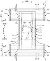
FIG. 4 is a sectional view of IVa-Iva and IVb-IVb of FIG. 3.
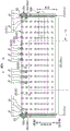
Fig. 5 is a schematic plan view of the abdominal belt member 31 in the developed state, as viewed from the non-skin side.
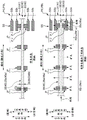
Fig. 6A and 6B are explanatory views illustrating the function of attaching the elastic thread 35(45) to the weld j.
Fig. 7 is a schematic plan view of the abdominal-side belt member 31(41) without the overlap weld jr as a comparative example, as viewed from the non-skin side.
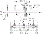
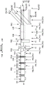
Fig. 8 is a schematic plan view showing a state in which the diaper 1 is manufactured in a production line in a partially perspective manner.
Fig. 9A, 9B, and 9C are a schematic enlarged view of a portion a, a schematic enlarged view of a portion B, and a schematic enlarged view of a portion C in fig. 8, respectively.
Fig. 10 is an enlarged schematic view of an example in which the formation pitch Pj of the welded portions j and j … in the conveyance direction is smaller than the size LSS of the side seal SS in the conveyance direction.
Fig. 11A is a schematic diagram for explaining an example of the overlapping state of the repeat welded portion jr and the side seal portion SS in detail.
Fig. 11B is a schematic diagram for explaining an example of the overlapping state of the repeat welded portion jr and the side seal portion SS in detail.
Fig. 12A is a schematic view of a case where a weld portion j (j1) other than the repeated weld portion jr is provided at a position between the side seal portion SS and the cutting target position PC in the conveyance direction.
Fig. 12B is a schematic view of a case where a welded portion j (j2) other than the repeated welded portion jr is provided so as to straddle the cutting target position PC in the conveying direction.
Fig. 13 is a schematic view of a case where the weld portion j (j3) is provided on one side of the weld portion SSk1 located on the most one side in the CD direction out of the weld portions SSk and SSk … of the side seal SS.
Fig. 14 is a schematic view of the aforementioned fig. 13 in which the end 31aeu in the CD direction of the two continuous pieces 32a, 33a of the abdomen-side belt member 31 protrudes to one side in the CD direction from the end 41aeu in the CD direction of the two continuous pieces 42a, 43a of the back-side belt member 41.
Fig. 15 is a schematic explanatory view of a positional relationship between the repeatedly welded portions jr of the continuous sheets 32a, 33a of the abdominal-side belt member 31 and the repeatedly welded portions jr of the continuous sheets 42a, 43a of the back-side belt member 41.
Detailed Description
At least the following matters will be made clear from the description of the present specification and the drawings.
A method for manufacturing an absorbent article having side seals formed by welding a 1 st sheet member and a 2 nd sheet member in a state of being overlapped in a thickness direction intersecting with the lateral direction, the 1 st sheet member and the 2 nd sheet member each having an elastic member attached thereto and being given lateral stretchability, the method comprising:
a placement step of placing a continuous body of the elastic member, which is continuous in the conveyance direction and is arranged in a state of being elongated in the conveyance direction, between a pair of opposing surfaces of the continuous body of the 1 st sheet-like member, the pair of opposing surfaces being opposed to each other, the continuous body of the 1 st sheet-like member being continuous in the conveyance direction, the continuous body of the elastic member being arranged in a plurality of rows at intervals in a CD direction intersecting both the conveyance direction and the thickness direction;
a joining portion forming step of forming a plurality of joining portions that join the pair of opposing surfaces of the continuous body of the 1 st sheet member to each other at intervals in the conveyance direction and the CD direction;
a superposing step of superposing a continuous body of the 2 nd sheet-like member continuous in the conveying direction on a continuous body of the 1 st sheet-like member on which the joining portions are formed in the thickness direction;
a side seal portion forming step of forming the side seal portions on both sides of a cutting target position, the side seal portions welding a continuous body of the 1 st sheet member and a continuous body of the 2 nd sheet member overlapped in the thickness direction, the cutting target position being set at a predetermined pitch in the conveying direction; and
a cutting step of cutting the continuous body of the 1 st sheet member, the continuous body of the elastic member, and the continuous body of the 2 nd sheet member at the cutting target position after the side seal portion forming step to produce the absorbent article having the elastic member, the 1 st sheet member, and the 2 nd sheet member,
in the joined portion forming step, the joined portions are formed at positions on both sides of the continuous body of the elastic member in the CD direction while maintaining a state in which the continuous body of the elastic member is stretched in the conveyance direction,
after the cutting step, the elastic member contracted in the conveying direction and expanded in the CD direction is attached to the 1 st sheet member by being pressed in the CD direction by the joining portions on both sides,
when the continuous body of the 1 st sheet member is viewed from the thickness direction, a part of at least one of the plurality of joining portions overlaps with at least a part of the side seal portion.
According to such a method of manufacturing an absorbent article, a part of at least one of the plurality of joint portions is provided so as to overlap at least a part of the side seal portion. The elastic member is attached to the 1 st sheet member based on the nipping and pressing of the joining portions. This can suppress the occurrence of a portion to which no stretchability is imparted in the 1 st sheet member in a range inward in the lateral direction in the conveying direction from the side seal portion.
In the method of manufacturing an absorbent article, it is preferable that at least one of the plurality of joint portions is provided at a position between the side seal portion and the cutting target position in the conveying direction.
According to the method of manufacturing an absorbent article, at least one joint is provided at a position between the side seal and the cutting target position in the conveyance direction. Thus, the elastic member is attached to the 1 st sheet member not only by the overlapping joint portions but also by the nipping and pressing of the joint portions. This makes it possible to more reliably prevent the occurrence of a portion to which no stretchability is imparted in the 1 st sheet member in a range inward in the lateral direction of the conveyance direction with respect to the side seal portion.
In the method of manufacturing an absorbent article, it is preferable that, when the joint portion overlapping the side seal portion among the plurality of joint portions is an overlapped joint portion,
at least one of the plurality of joining portions other than the overlapping joining portion is provided across the cutting target position in the conveying direction.
According to the method of manufacturing an absorbent article, at least one joint is provided across the position to be cut in the conveyance direction. Thus, the elastic member is attached to the 1 st sheet member not only by the overlapping joint portions but also by the nipping and pressing of the joint portions. This makes it possible to more reliably prevent the occurrence of a portion to which no stretchability is imparted in the 1 st sheet member in a range inward in the lateral direction of the conveyance direction with respect to the side seal portion.
In the method of manufacturing an absorbent article, it is preferable that the joining portions are provided for each of the continuous bodies of the elastic member,
the continuous body of at least one elastic member among the continuous bodies of the plurality of elastic members and the joining portion provided corresponding to the continuous body of the at least one elastic member are provided on the one side of the side seal portion on the most one side in the CD direction.
According to such a method of manufacturing an absorbent article, the joining portion provided corresponding to the continuous body of the at least one elastic member is provided on one side of the portion located on the most one side in the CD direction in the side seal portion. This can prevent the portion of the pair of opposing surfaces of the 1 st sheet member that is not joined to each other from being formed to be large at the end in the CD direction. This can prevent the pair of opposing surfaces from widely separating from each other by starting at the portion.
In the method of manufacturing an absorbent article, it is preferable that, when the joining portion provided on the one side of the side seal portion is a side joining portion, as compared with a portion of the side seal portion located on the most one side in the CD direction,
the portion of the 1 st sheet member where the one side joining portion is provided is a portion of the 1 st sheet member that protrudes to one side in the CD direction than the 2 nd sheet member.
According to the method of manufacturing an absorbent article, the one side joint portion is provided in the 1 st sheet-like member at a portion protruding to one side in the CD direction from the 2 nd sheet-like member. This can suppress the occurrence of a large portion in which the pair of opposing surfaces are not joined to each other even in a portion protruding in the CD direction in the 1 st sheet member. This can prevent the pair of opposing surfaces from widely separating from each other by starting at the portion.
In the method of manufacturing an absorbent article, it is preferable that no adhesive is provided in a portion of the continuous body of the 1 st sheet member and the continuous body of the 2 nd sheet member where the side seal portion is formed.
According to the method of manufacturing an absorbent article, no adhesive is provided at the portion where the side seal portion is formed. This can prevent a problem that may occur when the adhesive is provided in this portion, that is, a problem that the welding strength of the side seal portion is reduced due to the influence of the component of the adhesive.
In the method of manufacturing an absorbent article, it is preferable that the 2 nd sheet member is attached with a 2 nd elastic member to be provided with stretchability in the lateral direction,
the method for manufacturing the absorbent article comprises the following steps:
a 2 nd arranging step of arranging a continuous body of the 2 nd elastic member, which is continuous in the conveyance direction and is arranged in a state of being elongated in the conveyance direction, between a pair of opposing surfaces of the continuous body of the 2 nd sheet-like member, the pair of opposing surfaces opposing each other, wherein a plurality of the continuous bodies of the 2 nd elastic member are arranged at intervals in the CD direction; and
a 2 nd joining portion forming step of forming a plurality of 2 nd joining portions at intervals in the conveying direction and the CD direction, the plurality of 2 nd joining portions joining the pair of opposing surfaces of the continuous body of the 2 nd sheet-like member to each other,
in the overlapping step, the continuous body of the 2 nd sheet member on which the 2 nd joining portion is formed is overlapped with the continuous body of the 1 st sheet member on which the joining portion is formed in the thickness direction,
in the cutting step, the continuous body of the 1 st sheet-like member, the continuous body of the elastic member, the continuous body of the 2 nd sheet-like member, and the continuous body of the 2 nd elastic member are cut at the cutting target position to produce the absorbent article having the elastic member, the 1 st sheet-like member, the 2 nd elastic member, and the 2 nd sheet-like member,
in the 2 nd bonded part forming step, the 2 nd bonded parts are formed at positions on both sides of the 2 nd elastic member continuous body in the CD direction while maintaining a state in which the 2 nd elastic member continuous body is stretched in the conveyance direction,
after the cutting step, the 2 nd elastic member contracted in the conveying direction and expanded in the CD direction is attached to the 2 nd sheet member by being pressed in the CD direction by the 2 nd joining portions on both sides,
a part of at least one 2 nd joining part of the plurality of 2 nd joining parts overlaps with at least a part of the side seal part when the 2 nd sheet member continuum is viewed from the thickness direction.
According to the method of manufacturing such an absorbent article, the 2 nd elastic member and the 2 nd joint portion are provided in the 2 nd sheet-like member. This can provide the 1 st sheet member with lateral stretchability as well as the 2 nd sheet member with lateral stretchability.
In addition, a part of at least one 2 nd joint part among the plurality of 2 nd joint parts is provided so as to overlap with the side seal part. The elastic member is attached to the 2 nd sheet member based on the 2 nd joint portions being pressed against each other. This can suppress the occurrence of a portion to which no stretchability is imparted in the 2 nd sheet member in a range on the inner side in the lateral direction in the conveying direction than the side seal portion.
In the method of manufacturing an absorbent article, it is preferable that when the joint portion overlapping at least a part of the side seal portion in the continuous body of the 1 st sheet member is a 1 st overlap joint portion and the 2 nd joint portion overlapping at least a part of the side seal portion in the continuous body of the 2 nd sheet member is a 2 nd overlap joint portion,
in the overlapping step, the continuous body of the 1 st sheet-like member and the continuous body of the 2 nd sheet-like member are overlapped so that at least one 1 st repeating joint portion of the 1 st repeating joint portions is displaced in the conveyance direction or the CD direction with respect to a 2 nd repeating joint portion closest to the 1 st repeating joint portion of the 2 nd repeating joint portions.
According to such a method of manufacturing an absorbent article, at least one 1 st overlap joint portion is displaced in the conveyance direction or the CD direction with respect to a 2 nd overlap joint portion located closest to the 1 st overlap joint portion in the CD direction. This can prevent a problem that may occur when the 1 st overlap joint portion and the 2 nd overlap joint portion completely overlap each other, that is, a problem that a variation in rigidity of the side seal portion of the absorbent article becomes large and a person in contact with the side seal portion is likely to feel discomfort.
In the method of manufacturing an absorbent article, it is preferable that the overlapped joint portion is overlapped with the downstream side seal portion when the joint portion overlapped with the side seal portion among the plurality of joint portions is an overlapped joint portion and a side seal portion formed on a downstream side in the conveying direction among the side seal portions formed on both sides is a downstream side seal portion,
an upstream end of the overlap joint portion in the conveying direction is located on a downstream side in the conveying direction than an upstream end of the downstream side seal portion in the conveying direction.
According to such a method of manufacturing an absorbent article, the upstream end of the overlap joint section in the conveyance direction is located on the downstream side of the upstream end of the downstream side seal section in the conveyance direction. This can prevent the end of the elastic member, which moves downstream in the conveyance direction with contraction of the elastic member in the conveyance direction after cutting at the cutting target position, from protruding upstream in the conveyance direction relative to the downstream side sealing portion. This can maintain the appearance of the downstream side seal portion satisfactorily.
According to this method for manufacturing an absorbent article, it is preferable that the upstream end of the overlap joint section in the conveyance direction is located downstream in the conveyance direction from the center position of the downstream side seal section in the conveyance direction.
According to such a method of manufacturing an absorbent article, the upstream end of the overlap joint section in the conveyance direction is located downstream of the center position of the downstream side seal section in the conveyance direction. This can prevent the end of the elastic member, which moves downstream in the conveyance direction with contraction of the elastic member in the conveyance direction after cutting at the cutting target position, from protruding upstream in the conveyance direction from the position of the downstream side seal portion. Further, this can maintain the appearance of the downstream side seal portion satisfactorily.
In the method of manufacturing an absorbent article, it is preferable that at least some of the joint sections are provided at a predetermined formation pitch in the conveyance direction so as to straddle the side seal section and the position to be cut in the conveyance direction,
the size of the forming pitch is smaller than the size of the side seal portion in the conveying direction.
According to such a method of manufacturing an absorbent article, the size of the formation pitch of the joint section is smaller than the size of the side seal section in the conveyance direction. Thereby, at least one joint portion can be overlapped with the side seal portion.
Further, an apparatus for manufacturing an absorbent article having a side seal portion formed by welding a 1 st sheet member and a 2 nd sheet member in a state of being overlapped in a thickness direction intersecting with the lateral direction, the 1 st sheet member and the 2 nd sheet member being respectively attached with an elastic member and given lateral stretchability, the apparatus comprising:
a placement device configured to convey the continuous body of the elastic member, which is continuous in the conveyance direction, between a pair of opposing surfaces of the continuous body of the 1 st sheet-like member, which are opposed to each other, in a state where the continuous body of the elastic member, which is continuous in the conveyance direction, is stretched in the conveyance direction, and a plurality of the continuous bodies of the elastic member are arranged at intervals in a CD direction intersecting both the conveyance direction and the thickness direction;
a joining section forming device that forms a plurality of joining sections that join the pair of opposing surfaces of the continuous body of the 1 st sheet member to each other at intervals in the conveyance direction and the CD direction;
a superimposing device that superimposes a continuous body of the 2 nd sheet-like member that is continuous in the conveyance direction on a continuous body of the 1 st sheet-like member on which the joining portions are formed in the thickness direction;
a side seal forming device that forms the side seals on both sides of a position to be cut, the side seals welding a continuous body of the 1 st sheet member and a continuous body of the 2 nd sheet member that overlap each other in the thickness direction, the position to be cut being set at a predetermined pitch in the conveyance direction; and
a cutting device that cuts the continuous body of the 1 st sheet-like member, the continuous body of the elastic member, and the continuous body of the 2 nd sheet-like member at the position to be cut at a position downstream of the side seal portion forming device in the conveying direction to produce the absorbent article having the elastic member, the 1 st sheet-like member, and the 2 nd sheet-like member,
the joint forming device forms the joints at positions on both sides of the continuous body of the elastic member in the CD direction while maintaining a state in which the continuous body of the elastic member is stretched in the conveyance direction,
the elastic member that contracts in the conveyance direction and expands in the CD direction is attached to the 1 st sheet member by being pressed in the CD direction by the joining portions on both sides at a position downstream of the cutting device in the conveyance direction,
when the continuous body of the 1 st sheet member is viewed from the thickness direction, a part of at least one of the plurality of joining portions overlaps with at least a part of the side seal portion.
According to the apparatus for manufacturing an absorbent article, the same operational effects as those in the case of the manufacturing method can be obtained.
Further, an absorbent article having mutually orthogonal lateral, longitudinal and front-to-back directions, comprising:
a 1 st sheet member;
a 2 nd sheet member;
a plurality of elastic members interposed between a pair of opposing surfaces of the 1 st sheet member facing each other in the transverse direction and arranged at intervals in the longitudinal direction;
a plurality of engaging portions provided at intervals in the lateral direction and the longitudinal direction so as to engage the pair of opposing surfaces with each other;
a side seal portion formed by welding the 1 st sheet member and the 2 nd sheet member at each end in the lateral direction in a state of being overlapped in the front-rear direction,
the absorbent article is characterized in that,
the engaging portions are formed at positions on both sides of the elastic member in the longitudinal direction, respectively, and are brought into a state in which the elastic member is pinched by the engaging portions on both sides,
a part of at least one of the plurality of joining portions overlaps with at least a part of the side seal portion when the 1 st sheet member is viewed from the front-rear direction.
According to such an absorbent article, a part of at least one of the joint portions is provided so as to overlap at least a part of the side seal portion. The elastic member is attached to the 1 st sheet member based on the nipping and pressing of the joining portions. This can suppress the occurrence of a portion to which no stretchability is imparted in the 1 st sheet member in a range inward in the lateral direction in the conveying direction from the side seal portion.
In this embodiment, the present invention is not limited to the embodiment
The method and apparatus for manufacturing an absorbent article according to the present embodiment are used, for example, in a production line of a disposable diaper 1 as an example of an absorbent article. Fig. 2 is a schematic perspective view of a three-piece diaper 1 as an example of the diaper 1.
The diaper 1 has a "longitudinal direction", a "lateral direction" perpendicular to the longitudinal direction, and a "front-back direction" perpendicular to the longitudinal direction and the lateral direction in a pants-type state before being worn as shown in fig. 2. In addition, the diaper 1 is often worn with the longitudinal direction oriented in the vertical direction. Therefore, the longitudinal direction is also referred to as "vertical direction" hereinafter.
In the vertical direction, the upper side corresponds to the waist side of the wearer, and the lower side corresponds to the crotch side of the wearer. In the front-rear direction, the front side corresponds to the abdomen side of the wearer, and the rear side corresponds to the back side of the wearer. In the lateral direction, one side corresponds to the left side of the wearer, and the other side corresponds to the right side of the wearer.
In the pants-type state of fig. 2, the diaper 1 has: a ventral belt member 31 in the transverse direction; a back side belt member 41 located on the back side of the abdominal side belt member 31 in the transverse direction, the back side belt member 41 being for forming a waistline opening BH in the longitudinal direction side together with the abdominal side belt member 31; and an absorbent body 10 as a crotch part provided between the abdominal-side belt member 31 and the back-side belt member 41. The absorbent body 10 is positioned to protrude longitudinally downward from the abdominal-side belt member 31 and the back-side belt member 41.
The lateral end portions 31e and 31e of the abdominal-side belt member 31 and the corresponding lateral end portions 41e and 41e of the back-side belt member 41 are joined by a side seal portion SS. Thus, the abdominal-side belt member 31 and the back-side belt member 41 form the leg-surrounding openings LH and LH on the lower side and both lateral sides of the absorbent body 10.
Fig. 3 is a schematic plan view of the diaper 1 in an unfolded state as viewed from the skin side of the wearer. In addition, FIG. 4 is a sectional view of IVa-Iva in FIG. 3, and is also a sectional view of IVb-IVb in this FIG. 3.
Here, the developed state refers to a state in which the joining of the side seal portions SS provided on both lateral sides of the pants-type diaper 1 shown in fig. 2 is broken, the abdominal-side belt member 31 is separated from the back-side belt member 41, and the diaper 1 is developed in a plane by opening the diaper 1 in the longitudinal direction.
In the developed state, the diaper 1 is shown in a virtual state in which all the members constituting the diaper 1 are not stretchable. For example, in this example, the diaper 1 is provided with a plurality of elastic members 17, 18, 35, 45 for the purpose of imparting stretchability to the diaper 1, but in the developed state, the diaper 1 is shown in a virtual state in which all of the elastic members 17, 18, 35, 45 are non-stretchable (contractive force).
In the developed state, the diaper 1 has a longitudinal direction, a lateral direction, and a thickness direction (direction passing through the paper surface in fig. 3) which are three directions orthogonal to each other. Further, the longitudinal direction is along the aforementioned longitudinal direction. One side in the longitudinal direction corresponds to the ventral side, and the other side corresponds to the dorsal side. The longitudinal outer side corresponds to the longitudinal upper side, and the longitudinal inner side corresponds to the longitudinal lower side. In addition, since the longitudinal direction and the longitudinal direction are similar to each other in this manner, for convenience of description, the longitudinal direction may be used instead of the longitudinal direction in the expanded state. On the other hand, the lateral direction is synonymous with the lateral direction in the pants-type state. In the thickness direction, one side corresponds to a skin side that contacts the body of the wearer, and the other side corresponds to a non-skin side opposite thereto. Further, the thickness direction is along the aforementioned front-rear direction.
In the developed state of fig. 3, the abdominal-side belt member 31 is disposed along the lateral direction, and the back-side belt member 41 is disposed along the lateral direction at a position spaced apart from the abdominal-side belt member 31 by a predetermined distance in the longitudinal direction. The absorbent main body 10 is stretched between the abdominal-side belt member 31 and the back-side belt member 41 along the longitudinal direction, and the respective ends 10ea and 10eb in the longitudinal direction of the absorbent main body 10 are joined and fixed to the nearest respective belt members 31 and 41, respectively, whereby the appearance shape thereof is substantially H-shaped in plan view. Further, when the diaper 1 is folded in two from this state with the predetermined position CL1 in the longitudinal direction of the absorbent main body 10 (the center position CL1 in the longitudinal direction of the diaper 1) as the folded position, and the end portions 31e, 41e in the lateral direction of the belt members 31, 41 which are opposed to each other are joined to each other by the side seal portions SS in this folded-in state, the belt members 31, 41 are connected to each other in a loop shape, and thereby the pants-type diaper 1 in which the waist opening BH and the pair of leg openings LH, LH are formed as shown in fig. 2 is obtained.
The absorbent main body 10 has a substantially rectangular shape in a plan view in the developed state of fig. 3. The longitudinal direction of the absorbent main body 10 is arranged along the longitudinal direction of the diaper 1. As shown in fig. 4, the absorbent main body 10 includes an absorbent body 11, a liquid-permeable top sheet 13 covering the absorbent body 11 from the skin side and serving as the skin-side surface of the absorbent main body 10, and a liquid-impermeable back sheet 15 covering the absorbent body 11 from the non-skin side and serving as the non-skin-side surface of the absorbent main body 10.
The absorber 11 has a liquid-absorbent core 11c and a core covering sheet, not shown, covering the outer peripheral surface of the core 11 c. The absorbent core 11c is a molded body formed by molding a liquid-absorbent material such as pulp fibers or a super absorbent polymer into a substantially hourglass shape in a plan view, which is an example of a predetermined shape. In addition, a liquid permeable sheet such as a tissue or a nonwoven fabric may be used for the core covering sheet, but the core covering sheet may not be provided. The shape of the absorbent core 11c is not limited to the substantially hourglass shape in the plan view, and may be other shapes.
The top sheet 13 is a liquid-permeable flexible sheet such as a nonwoven fabric. The back sheet 15 is a liquid-impermeable flexible sheet. As an example of the backsheet 15, there is a laminate sheet 15 having a two-layer structure, and the laminate sheet 15 has a liquid-impermeable leakproof sheet such as a polyethylene film or a polypropylene film, and an exterior sheet made of a nonwoven fabric attached to the non-skin side of the leakproof sheet.
As shown in fig. 3, at least the back sheet 15 is a flat sheet protruding in the longitudinal direction and the lateral direction from the absorbent body 11. In addition, leg gathers LG that extend and contract in the longitudinal direction are formed in the portions that protrude in the lateral direction. That is, the elastic thread 17 as an elastic member extending in the longitudinal direction is fixed to the protruding portion in a state of being stretched in the longitudinal direction, and thereby, the stretchable leg gathers LG are formed in the portion.
As shown in fig. 3 and 4, the absorbent body 10 has three-dimensional gathers LSG and LSG as leakage-preventing walls at each end in the lateral direction for the purpose of preventing side leakage. That is, the elastic members 18 are provided at the respective ends in the lateral direction of the absorbent main body 10 as a structure in which the elastic threads 18 along the longitudinal direction are attached to the sheet-like portions that become the three-dimensional gathers LSG in a state of being stretched in the longitudinal direction.
As shown in fig. 3, the abdominal belt member 31 is a sheet-like member having a substantially rectangular shape in plan view, made of two nonwoven fabrics 32 and 33. That is, as shown in fig. 4, the two nonwoven fabrics 32 and 33 are overlapped with each other in the thickness direction, and a pair of opposing surfaces facing each other are joined by a plurality of fusion portions j and j … (corresponding to joining portions) discretely arranged in the longitudinal direction (longitudinal direction) and the lateral direction as shown in fig. 5 described later. As shown in fig. 3, the abdominal belt member 31 is disposed so as to protrude laterally on both sides of the absorbent body 10, and is joined to the abdominal end 10ea of the absorbent body 10 so as to overlap from the non-skin side.
In this example, a spunbond nonwoven fabric is used for both the two nonwoven fabrics 32 and 33 of the abdominal belt member 31. However, the present invention is not limited to this, and other types of nonwoven fabrics such as SMS (spunbond/meltblown/spunbond) nonwoven fabrics may be used. In this example, a single fiber of polypropylene (PP), which is a typical example of thermoplastic resins, is used as the constituent fiber of the nonwoven fabric, but the present invention is not limited to this. For example, a single fiber of another thermoplastic resin such as Polyethylene (PE) may be used, and a composite fiber having a sheath-core structure such as PE and PP may be used. The same applies to the back side belt member 41 described later.
The back belt member 41 is a sheet-like member having a substantially rectangular shape in plan view, which is made of two nonwoven fabrics 42 and 43, as in the abdominal belt member 31. That is, as shown in fig. 4, the two nonwoven fabrics 42 and 43 are overlapped with each other in the thickness direction, and a pair of opposing surfaces facing each other are joined by discretely disposing a plurality of welded portions j and j … (corresponding to the 2 nd joined portion) in the longitudinal direction (longitudinal direction) and the lateral direction, as in the case of the abdominal-side belt member 31 in fig. 5. As shown in fig. 3, the back-side belt member 41 is disposed so as to protrude laterally on both sides of the absorbent body 10, and is joined to the back-side end portion 10eb of the absorbent body 10 so as to overlap from the non-skin side.
In the following description, the abdominal belt member 31 will be described as a representative of the common contents of both the abdominal belt member 31 and the back belt member 41, and the back belt member 41 will be indicated by the reference numerals of the corresponding members and the like in parentheses.
Fig. 5 is a schematic plan view of the abdominal belt member 31 in the developed state, as viewed from the non-skin side.
As shown in fig. 5, the side seal portions SS are provided at the respective ends 31e and 31e (41e and 41e) of the abdominal-side band member 31(41) in the lateral direction. In this example, the side seal portion SS has a plurality of weld portions SSk, SSk … arranged in a straight line along the longitudinal direction and having the same shape as each other. The fusion-bonded portions SSk fuse the nonwoven fabric 33 of the abdominal-side belt member 31 and the nonwoven fabric 43 of the back-side belt member 41, fuse a pair of opposing surfaces of the two nonwoven fabrics 32 and 33 of the abdominal-side belt member 31 that face each other, and fuse a pair of opposing surfaces of the two nonwoven fabrics 42 and 43 of the back-side belt member 41 that face each other.
As shown in fig. 5, a plurality of elastic threads 35, 35 … (45, 45 …) as elastic members (2 nd elastic members) extending in the transverse direction are interposed between the pair of facing surfaces of the two nonwoven fabrics 32, 33(42, 43) of the abdominal belt member 31(41) in a longitudinally aligned manner, and the elastic threads 35, 35 … (45, 45 …) are attached to the nonwoven fabrics 32, 33(42, 43) by the fusion portions j, j …. Thereby, the abdominal belt member 31(41) is given lateral stretchability. That is, the welded portions j and j … have not only a function of joining a pair of opposing surfaces of the two nonwoven fabrics 32 and 33(42 and 43) to each other, but also a function of attaching the elastic threads 35(45) to the two nonwoven fabrics 32 and 33(42 and 43).
Fig. 6A and 6B are explanatory views of the latter function of the welded portion j, i.e., the function of attaching the elastic thread 35(45), and are schematic enlarged views of the VI portion in fig. 5.
As shown in fig. 5, the welded portions j and j … are provided for each of the elastic threads 35(45) arranged in the transverse direction. The fusion-bonded portion j is formed in a pair on both sides of the corresponding elastic thread 35 in the longitudinal direction, that is, a pair of fusion-bonded portions j, j arranged on both sides in the longitudinal direction are formed as a fusion-bonded portion pair jP. The pair of fusion-spliced portions jP is formed in a plurality of pairs aligned in the transverse direction with a space between the pair of fusion-spliced portions jP adjacent in the transverse direction. On the other hand, as shown in fig. 6A, the pair of fusion-bonded portions j, j forming the pair of fusion-bonded portions jP are arranged at a distance Dj in the longitudinal direction, and the distance Dj is set to be equal to or slightly larger than the dimension D35t (D45t) in the longitudinal direction of the elastic thread 35(45) in a state of being stretched in the lateral direction to the target stretch ratio. In the pants-type diaper 1 of fig. 2, the elastic threads 35(45) relax from the extended state at the above-described extension ratio. Accordingly, in this pants-type state, as shown in fig. 6B, the elastic threads 35(45) attempt to contract in the lateral direction and expand in the longitudinal direction, but here, expansion in the longitudinal direction of the elastic threads 35(45) is restricted by the pair of welded portions j, j based on the dimensional relationship. Accordingly, the elastic thread 35(45) is substantially longitudinally compressed by the fusion-bonded portions j and j, and as a result, the elastic thread 35(45) is attached to the abdominal-side belt member 31 (41).
The extension ratio is a value R (L1/L0) representing that the entire length L1 of the elastic strand 35(45) is extended to several times the entire length L0 in an unloaded state, which is a natural length. The target extension ratio is selected from, for example, 1.5 to 4.0 times.
As shown in fig. 5 and 6B, when the abdominal belt member 31(41) is viewed in the thickness direction, a part of at least one welded portion j of the plurality of welded portions j, j … overlaps with the welded portion SSk (corresponding to a part of the side seal portion) of the side seal portion SS. Hereinafter, the welding portion j thus overlapped is also referred to as a "overlapped welding portion jr (corresponding to an overlapped joint portion)", and the above-described problem, that is, the following problem can be suppressed by the overlapped welding portion jr.
First, as shown in fig. 5, in the abdominal belt member 31(41), a range R31(R41) laterally inward of the weld portion SSk of the side seal portion SS is a portion that comes into contact with the body of the wearer from the abdominal side. Therefore, it is preferable that substantially the entire region in the lateral direction in the inner range R31(R41) has elasticity.
On the other hand, in the case where the above-described repeatedly welded portion jr is not present as in the comparative example of fig. 7, when the elastic thread 35(45) contracts in the lateral direction while the extended state is relaxed from the state of fig. 6A to the state of fig. 6B, the end portion 35e in the lateral direction of the elastic thread 35 may move to the above-described inner range R31(R41) in the abdominal-side belt member 31(41) and enter the range R31(R41) as in fig. 7. Then, in the inner range R31(R41), the transverse end portion R31e (R41e) is in a state where the elastic thread 35(45) is not present, and as a result, the end portion R31e (R41e) is not provided with stretchability.
However, in this regard, if the repeatedly welded portion jr is provided as in the example of fig. 5, when the extended state of the elastic wire 35(45) is relaxed from the state of fig. 6A to the state of fig. 6B, the repeatedly welded portions jr and jr are pressed against each other at the position of the welded portion SSk of the side seal portion SSk, thereby preventing the end portion 35e (45e) of the elastic wire 35(45) from moving into the inner range R31 (R41). This can suppress the occurrence of a portion to which no stretchability is imparted in the inner region R31 (R41).
In the example of fig. 5, the repeatedly welded portions jr are provided to all the elastic threads 35 and 35 … (45 and 45 …) provided in the abdominal-side belt member 31(41), but the present invention is not limited to this. For example, if the repeatedly welded portions jr are provided to at least one, preferably one-third or more, more preferably one-half or more, and even more preferably two-thirds or more of the elastic threads 35(45) in all the elastic threads 35(45) of the abdominal belt member 31(41), the above-described problems can be suppressed at least in the elastic threads 35(45) provided with the repeatedly welded portions jr. Therefore, the elastic threads 35(45) having no repeating weld jr may be present in all the elastic threads 35(45) of the abdominal-side belt member 31 (41).
In this production line, for example, the two nonwoven fabrics 32 and 33 (corresponding to the 1 st sheet member) of the abdominal-side belt member 31 are conveyed in the form of continuous sheets 32a and 33a (corresponding to the 1 st sheet member) that are continuous in the conveyance direction, and similarly, the two nonwoven fabrics 42 and 43 (corresponding to the 2 nd sheet member) of the back-side belt member 41 are conveyed in the form of continuous sheets 42a and 43a (corresponding to the 2 nd sheet member) that are continuous in the conveyance direction. Then, each time the two continuous sheets 32a, 33a, 42a, and 43a pass through a plurality of processing positions PK1 to PK5 set in the conveyance direction, the two continuous sheets 32a, 33a, 42a, and 43a are subjected to processing corresponding to the processing positions PK1 and PK2 …, respectively.
Here, when the direction orthogonal to both the thickness direction and the conveyance direction of the continuous sheets 32a, 33a, 42a, and 43a is defined as the "CD direction", in this example, the two continuous sheets 32a, 33a, 42a, and 43a, that is, the two continuous sheets 32a and 33a of the abdomen-side belt member 31 and the two continuous sheets 42a and 43a of the back-side belt member 41 are conveyed so as to be aligned with each other in the CD direction. However, the present invention is not limited to this.
In this example, the 1 st processing position PK1 to the 5 th processing position PK5 are set as the plurality of processing positions in order from the upstream side to the downstream side in the conveying direction. The processing at each of the processing positions PK1 and PK2 … is substantially the same as the processing of the two continuous sheets 32a and 33a of the abdomen-side belt member 31 and the processing of the two continuous sheets 42a and 43a of the back-side belt member 41.
Therefore, the common contents will be described below without distinguishing the abdominal-side belt member 31 and the back-side belt member 41. For example, only the "tape member 31 (41)" or only the "two continuous sheets 32a and 33a (42a and 43 a)" will be described. In this case, like the " continuous pieces 32a, 33a (42a, 43 a)", "elastic thread 35 (45)", "continuous body of elastic thread 35a (45 a)", and the like, the reference numerals following the terms indicating the respective members are those of the abdominal-side band member 31, and the reference numerals in parentheses following the same are those of the back-side band member 41.
As shown in fig. 8, the two continuous sheets 32a and 33a (42a and 43a) of each belt member 31(41) are conveyed in a so-called lateral conveying manner. That is, the two continuous sheets 32a and 33a (42a and 43a) are conveyed in a posture in which the direction corresponding to the lateral direction of the diaper 1 is oriented in the conveyance direction. Therefore, in the two continuous sheets 32a and 33a (42a and 43a), the boundary position PBL between the diapers 1 and 1 adjacent in the transverse direction is virtually set at the product pitch P1 in the transport direction. Then, at the 5 th processing position PK5 located at the tail end of the production line, the two continuous sheets 32a and 33a (42a and 43a) are cut at the boundary position PBL as the cutting target position PC, thereby producing the diaper 1 in a single sheet form.
The two continuous pieces 32a and 33a (42a and 43a) of each belt member 31(41) are conveyed by an appropriate conveying device (not shown) such as a belt conveyor and/or a conveying roller. Accordingly, unless otherwise specified, the two continuous sheets 32a and 33a (42a and 43a) are conveyed in the conveying direction by these conveying devices. Examples of the belt conveyor include a normal belt conveyor having an endless belt driven in a circumferential direction as a conveying surface, a suction belt conveyor having a suction function on an outer circumferential surface of the endless belt, and the like.
In this example, the stretchability of the continuous sheets 32a, 33a, 42a, and 43a is very small and negligible compared to the stretchability of the elastic threads 35 and 45. The continuous sheets 32a, 33a, 42a, and 43a are conveyed in a stretched state in the conveyance direction in the range from the 1 st processing position PK1 to the 5 th processing position PK 5.
Hereinafter, the process for manufacturing the diaper 1 will be described in detail.
As shown in fig. 8, first, the two continuous sheets 32a and 33a (42a and 43a) of each belt member 31(41) pass through the 1 st processing position PK 1. In this passage, as shown in fig. 8 and 9A, the two continuous sheets 32a and 33a (42a and 43a) overlap each other in the thickness direction. In addition, at the time of overlapping, the continuous bodies 35a, 35a … (45a, 45a …) of elastic threads that are continuous in the conveyance direction as continuous bodies of elastic members (continuous bodies of the 2 nd elastic member) are interposed between a pair of opposing surfaces that oppose each other in the two continuous sheets 32a, 33a (42a, 43a) in a plurality of rows in the CD direction in a state of being extended in the conveyance direction at the target extension ratio (corresponding to the disposing step and the 2 nd disposing step).
The continuous body 35a (45a) of elastic thread is disposed on the pair of opposing surfaces by a conveying device (corresponding to a disposing device) such as a conveying roller (not shown).
At the same time as or immediately after the overlapping, as shown in fig. 9B, the fusion portions j, j … as the joint portions (2 nd joint portions) are formed on the two continuous sheets 32a, 33a (42a, 43a), whereby the pair of opposing surfaces of the two continuous sheets 32a, 33a (42a, 43a) are joined to each other by the fusion portions j, j … (corresponding to the joint portion forming step and the 2 nd joint portion forming step).
Here, as described above, in this production line, the lateral direction of the diaper 1 is along the conveyance direction, and the longitudinal direction of the diaper 1 is along the CD direction. Therefore, the welded portions j are formed as a pair on both sides in the CD direction of the continuous body 35a (45a) of elastic thread. That is, as shown in fig. 9B, a pair of fusion-bonded portions j, j arranged on both sides of the continuous body 35a (45a) in the CD direction are a fusion-bonded portion pair jP. The pair of welding portions jP is arranged in a plurality of pairs in the conveying direction with a space between adjacent welding portion pairs jP in the conveying direction.
The pair of fusion-bonded portions j, j forming the pair of fusion-bonded portions jP are arranged at an interval Dj in the CD direction as shown in fig. 6A, where the interval Dj is equal to or slightly larger than the dimension D35t (D45t) in the CD direction of the continuous body 35a (45a) of the elastic thread in a state of being elongated in the conveyance direction to the target elongation magnification, that is, in a state of being at the 1 st processing position PK 1.
Therefore, when the continuous body 35a (45a) of elastic threads is cut at the later-described 5 th processing position PK5 and the extension state of the elastic threads 35(45) is relaxed, as shown in fig. 6B, the pair of fusion-bonded portions j, j sandwich the elastic threads 35(45) which attempt to contract in the conveyance direction and expand in the CD direction from each other, thereby bringing the elastic threads 35(45) into a state of being attached to the two nonwoven fabrics 32, 33(42, 43) of the belt member 31 (41).
As is clear from a comparison between fig. 9B and 9C, when the continuous sheets 32a and 33a (42a and 43a) are viewed in the thickness direction, a part of at least one welded portion j of the plurality of welded portions j and j … overlaps with a welded portion SSk of the side seal SS formed later. That is, the aforementioned repeatedly welded portion jr (j) is provided. Thus, when the continuous bodies 35a, 35a … (45a, 45a …) of elastic threads are cut together with the two continuous sheets 32a, 33a (42a, 43a) at the cutting target position PC at the later-described 5 th processing position PK5, the end portion 35e (45e) of the elastic thread 35(45) whose elongation state is relaxed can be suppressed by repeating the nipping pressure of the welded portions jr (j), and the like, and thus, as shown in fig. 5, the end portion 35e (45e) can be left substantially at the position of the side seal SS. As a result, the end portion 35e (45e) can be prevented from entering the range R31(R41) laterally inward of the weld portion SSk of the side seal portion SS in each of the tape members 31 (41).
Further, such reliable installation of the repeated fusion portion jr (j) can be achieved as follows, for example. That is, as shown in fig. 10, first, a plurality of welded portions j, j … are provided at a predetermined formation pitch Pj in the conveying direction so as to straddle the position of the side seal SS and the cutting target position PC in the direction. In this example, the welded portions j and j … are provided at the above formation pitch Pj over the entire length in the conveyance direction. When the 4 th processing position PK4 compares the size of the formation pitch Pj with the size LSS of the side seal SS in the conveyance direction, the size of the former formation pitch Pj is set smaller than the size LSS of the latter side seal SS. In this example, the size LSSk is smaller than the size LSSk in the conveyance direction of the welded portion SSk of the side seal SS. In this way, a part of at least one welded portion j can be reliably overlapped with the side seal portion SS, that is, the repeated welded portion jr can be reliably formed.
In this example, as shown in fig. 9C, the side seal portion SS is formed of a plurality of weld portions SSk and SSk … having the same shape and arranged on a straight line in the CD direction. Therefore, the positions of the upstream end SSeu and the downstream end SSed in the conveying direction in the side seal SS coincide with the positions of the upstream end SSkeu and the downstream end SSked in the conveying direction in the welding portion SSk, respectively, and thus the size LSS in the conveying direction of the side seal SS and the size LSSk in the conveying direction of the welding portion SSk are equal to each other as shown in fig. 10. Thus, as described above, the comparison target of the formation pitch Pj can be the size LSSk of the weld portion SSk instead of the size LSS of the side seal portion SS.
However, although not shown, if the side seal section SS includes a plurality of welding sections SSk and SSk … in the conveyance direction, the above cannot be achieved. That is, in this case, the upstream end SSkeu of the fusion-spliced portion SSk located most upstream in the conveyance direction among the plurality of fusion-spliced portions SSk, SSk … of the side seal SS becomes the upstream end SSeu of the side seal SS, while the downstream end SSked of the fusion-spliced portion SSk located most downstream in the conveyance direction among the plurality of fusion-spliced portions SSk, SSk … of the side seal SS becomes the downstream end SSed of the side seal SS. Thus, the size LSS of the side seal portion SS is equal to the interval in the conveyance direction between the upstream end SSkeu of the welding portion SSk located most upstream and the downstream end SSked of the welding portion SSk located most downstream. Note that, the midpoint between the upstream end SSkeu of the welding portion SSk located most upstream and the downstream end SSked of the welding portion SSk located most downstream in the central position CSS in the conveyance direction of the side seal SS in this case is referred to, and the definitions of the upstream end SSeu, the downstream end SSed, and the central position CSS of the side seal SS are the same in the case of each example described later with reference to fig. 11A and 11B.
The formation of the welded portion j including the overlapped welded portion jr can be performed using, for example, a heat sealing device or an ultrasonic sealing device (corresponding to a joint portion forming device), which are not shown. The heat sealing device includes, for example, a pair of rollers that heat while rotating in the conveyance direction. One roll is a heated embossing roll having a convex portion corresponding to each welded portion j on the outer peripheral surface, and the other roll is an anvil roll receiving the convex portion on a smooth outer peripheral surface. In addition, the ultrasonic sealing device includes: the horn has an oscillating surface that oscillates in, for example, a normal direction, and the anvil roller rotates in the conveyance direction. The anvil roll has a convex portion corresponding to each welded portion j on the outer circumferential surface so as to receive the vibration surface.
Next, as shown in fig. 8, both the two continuous sheets 32a, 33a of the abdomen-side belt member 31 and the two continuous sheets 42a, 43a of the back-side belt member 41 pass through the second processing position PK 2. In this passage, the single-piece absorbent body 10 produced in another step, not shown, is stretched and fixed between the two continuous pieces 32a, 33a of the abdominal-side belt member 31 and the two continuous pieces 42a, 43a of the back-side belt member 41, thereby forming a continuous body 1hs of a substantially ladder-shaped diaper formed by the diapers 1H, 1H … developed into a substantially H-shape and continuing.
The absorbent main body 10 can be fixed by using, for example, a rotary drum device not shown. The rotary drum device includes a rotary drum that rotates in, for example, a conveyance direction, and has a plurality of holding portions that detachably hold the absorbent body 10 on an outer circumferential surface.
Subsequently, the continuous body 1hs of the substantially ladder-shaped diaper passes through the 3 rd processing position PK 3. At the time of this passage, the absorbent body 10 is folded in two at a predetermined position CL1 in the CD direction in the absorbent body 10, and thereby the two continuous sheets 32a, 33a of the abdomen-side belt member 31 and the two continuous sheets 42a, 43a of the back-side belt member 41 are overlapped in the thickness direction (corresponding to the overlapping step).
This folding-in-half process can be performed using, for example, a folding guide device (corresponding to a superimposing device) not shown. The bending guide device includes a guide plate and a guide roller arranged at predetermined positions in the conveyance direction, for example. The guide plates and the guide rollers guide the continuous body 1hs of the substantially ladder-shaped diaper passing through the arrangement position so that the continuous body 1hs is folded in two.
Subsequently, the continuous body 1hsb of the diaper in the folded state passes through the 4 th processing position PK 4. In this passage, the two continuous pieces 32a and 33a of the abdominal-side belt member 31 and the two continuous pieces 42a and 43a of the back-side belt member 41, which are overlapped in the thickness direction, are welded at respective positions on both sides of the cutting target position PC in the conveyance direction to form a pair of side seal portions SS and SS (corresponding to the side seal portion forming step), whereby the continuous body 1hsb of the diaper is fixed in a folded-back state. As a result, a continuous body 1s of a plurality of pants- type diapers 1, 1 … joined in the transverse direction is formed.
Here, since the CD direction is along the longitudinal direction of the diaper 1, the side seal SS has a plurality of welds SSk and SSk … arranged in the CD direction as shown in fig. 9C. The respective welding portions SSk weld the continuous sheet 33a of the abdominal-side belt member 31 and the continuous sheet 43a of the back-side belt member 41 to each other, weld a pair of facing surfaces of the continuous sheets 32a and 33a of the abdominal-side belt member 31 to each other, and weld a pair of facing surfaces of the continuous sheets 42a and 43a of the back-side belt member 41 to each other (fig. 8).
In the example of fig. 9C, the planar shape of each welding portion SSk is a horizontally long rectangular shape that is longer in the lateral direction, i.e., the CD direction, than in the longitudinal direction, i.e., the conveyance direction. But is not at all limited thereto. For example, the shape may be a parallelogram shape or an elliptical shape, or may be other shapes. In this example, the longitudinal direction of each weld portion SSk is along the lateral direction, which is the conveying direction, but the present invention is not limited to this. That is, the longitudinal direction of each fusion-spliced portion SSk may be along the longitudinal direction, which is the CD direction, or may be oriented in a direction intersecting both the lateral direction and the longitudinal direction.
In this example, no adhesive is provided on the portions of the continuous sheets 32a and 33a of the abdomen-side belt member 31 and the continuous sheets 42a and 43a of the back-side belt member 41 where the side seal portions SS are formed, that is, the portions where the fusion-bonded portions SSk and SSk … are formed. This can prevent a problem that may occur when the adhesive is provided in this portion, that is, a problem that the welding strength of the side seal SS is reduced due to the influence of the components of the adhesive.
The side seal SS can be formed using, for example, a heat sealing device (not shown) or an ultrasonic sealing device (corresponding to a side seal forming device). The heat sealing device includes, for example, a pair of rollers that heat while rotating in the conveyance direction. One roller is a heated embossing roller having convex portions on the outer peripheral surface thereof corresponding to the respective welding portions SSk of the side seal portions SS, and the other roller is an anvil roller receiving the convex portions on the smooth outer peripheral surface thereof. Further, the ultrasonic sealing device includes: the horn has an oscillating surface that oscillates in, for example, a normal direction, and the anvil roller rotates in the conveyance direction. The anvil roll has a convex portion corresponding to each welded portion SSk on the outer circumferential surface thereof to receive the vibration surface.
Subsequently, as shown in fig. 8, the continuous body 1s of the pants-type diaper passes through a 5 th processing position PK 5. Then, during the passage, the continuous body 1s is cut at the cutting target position PC located between the pair of side seal portions SS, SS (corresponding to a cutting step), thereby manufacturing the diaper 1.
In this cutting operation, the two continuous pieces 32a and 33a (42a and 43a) and the continuous bodies 35a and 35a … (45a and 45a …) of the elastic threads of the abdominal-side belt member 31 and the back-side belt member 41 are cut at the cutting target position PC. Then, by relaxing the extended state of the elastic thread 35(45) due to this, the elastic thread 35(45) is attached to each of the belt members 31 and 41 by the nipping of the pair of fusion portions j and j of the fusion portion pair jP, as described in the description of the processing position PK1 of fig. 1.
This cutting can be performed using, for example, a cutting device (corresponding to a cutting device) not shown. The cutting device has a pair of rollers that rotate in, for example, a conveyance direction. One of the rollers is a cutter roller having a cutter blade on its outer peripheral surface, and the other roller is an anvil roller receiving the cutter blade on its outer peripheral surface.
Fig. 11A and 11B are schematic views for explaining an example of the overlapping state of the repeated fusion portion jr and the side seal portion SS in detail. Each of these figures is a schematic plan view of a portion in the vicinity of the cutting target position PC in the continuous body 1s of the pants-type diaper immediately before cutting at the 5 th processing position PK5, as viewed in the thickness direction.
The following description is common to both the overlap weld jr of the abdomen-side belt member 31 and the overlap weld jr of the back-side belt member 41. Therefore, only the former will be described herein as representative of the two, and the latter will not be described.
As described above with reference to fig. 6A and 6B, after the continuous body 1s of diapers is cut at the cutting target position PC, the end portions 35e and 35e of the elastic thread 35 are formed on both sides of the cutting target position PC in the conveyance direction. As a result, as shown in fig. 11A, in the continuous body 35a of elastic wire, the parts 35ae serving as the end portions 35e of the elastic wire 35 are positioned on both sides of the cutting target position PC in the conveying direction. On the other hand, the repeated welding portions jr finally attach the end portions 35e to the pair of opposing surfaces of the continuous sheets 32a and 33 a. Therefore, in each of the examples of fig. 11A and 11B, the overlapped fusion-spliced portions jr are formed on both sides of the cutting target position PC in the conveying direction.
The repeated welding portions jr and jr on both sides are substantially line-symmetric with respect to the cutting position PC. Similarly, the side seal portions SS and SS formed on both sides of the cutting target position PC are also formed substantially in line symmetry with respect to the cutting target position PC. Therefore, only the overlapped fusion splices jr and the side seals SS located on the downstream side in the conveying direction from the cutting target position PC will be described below, and the overlapped fusion splices jr and the side seals SS located on the upstream side will not be described.
In the following description, of the pair of side seals SS, SS formed on both sides of the cutting target position PC in the conveying direction, the side seal SS located on the downstream side in the conveying direction is also referred to as a "downstream side seal SSd", and the side seal SS located on the upstream side is also referred to as an "upstream side seal SSu".
In the example of fig. 11A, the welding portion j at the position closest to the cutting target position PC among the plurality of welding portions j, j … is the overlap welding portion jr. Further, the upstream end jreu of the overlap fusion-spliced portion jr in the conveyance direction is located downstream in the conveyance direction from the upstream end SSdeu of the downstream side seal SSd in the conveyance direction. More specifically, in this example, the upstream end SSkreu in the conveyance direction of the fusion bonded portion SSkr where the repeated fusion bonded portion jr overlaps among the fusion bonded portions SSk and SSk … of the downstream side sealing portion SSd is located downstream in the conveyance direction.
This can suppress the end 35e of the elastic thread 35, which moves downstream in the conveyance direction with the contraction of the elastic thread 35 in the conveyance direction after cutting at the cutting target position PC, from protruding upstream in the conveyance direction from the position of the downstream side seal SSd. Further, this can improve the appearance of the downstream side sealing portion SSd.
However, the present invention is not limited to this. For example, as shown in fig. 12A described later, the weld j closest to the cutting target position PC among the plurality of welds j, j … may not be the repeated weld jr, and this is also the case in fig. 11B described later.
The above-described operational effects can be obtained by the repeated welding portions jr of the continuous body 35a of at least one elastic thread having the above-described positional relationship. Therefore, it is not necessary to make the overlapped fusion portions jr, jr … of the continuous bodies 35a, 35a … of all elastic threads in fig. 9C have the positional relationship as described above. For example, the repeated welded portions jr, jr … of the continuous bodies 35a, 35a … of one-third or more, or one-half or more, or two-thirds or more of the continuous bodies 35a, 35a … of all elastic threads may be in the above-described positional relationship, which is the same in the example of fig. 11B described later.
Further, the positional relationship as shown in fig. 11A between the repeatedly welded portion jr and the side seal portion SS can be realized by setting the arrangement pattern of the convex portions on the outer peripheral surface of the roller of the heat sealing device or the ultrasonic sealing device arranged at the 1 st processing position PK1 and the arrangement pattern of the convex portions on the outer peripheral surface of the roller of the heat sealing device or the ultrasonic sealing device arranged at the 4 th processing position PK4, for example. This is also the same for the implementation of the examples of fig. 11B to 12B described below.
On the other hand, in the example of fig. 11B, the welding portion j at the position closest to the cutting target position PC among the plurality of welding portions j, j … is the overlap welding portion jr. The upstream end jreu of the overlap fusion-bonded portion jr in the conveyance direction is located downstream in the conveyance direction from the center position CSS of the downstream side seal portion SSd in the conveyance direction. More specifically, in this example, the welded portion SSkr overlapped by the overlapped welded portion jr among the plurality of welded portions SSk and SSk … of the downstream side seal SSd is located on the downstream side in the conveying direction from the central position CSSkr in the conveying direction. This can more reliably suppress the protrusion of the end 35e of the elastic thread 35.
As shown in fig. 12A, at least one welded portion j (j1) may be provided between the side seal SS and the cutting target position PC in the conveyance direction. In this manner, after the cutting step at the 5 th processing position PK5, the elastic thread 35 is attached to the two nonwoven fabrics 32 and 33 of the abdominal belt member 31 not only by the repeated fusion j r but also by the compression of the fusion j1 and j 1. This can more reliably prevent the two nonwoven fabrics 32 and 33 from having a portion to which no stretchability is imparted in the range R31 laterally inward of the side seal SS in the conveying direction.
More preferably, as shown in fig. 12B, at least one welded portion j (j2) other than the repeated welded portion jr may be provided across the cutting target position PC in the conveying direction. This also provides the same suppression effect as described above.
In this example, as shown in fig. 9B, a plurality of elastic cord continuous bodies 35a, 35a … are arranged in a line in the CD direction, and the above-described fusion portions j, j are provided for each of the elastic cord continuous bodies 35a, and here, preferably, as shown in fig. 13, at least one of the elastic cord continuous bodies 35a, 35a … may be provided on one side of a fusion portion SSk1 (corresponding to "a portion located on the most side in the CD direction in the side seal portion") located on the most side in the CD direction among the fusion portions SSk, SSk … of the side seal portion SS, and the fusion portions j, j provided in correspondence with the elastic cord continuous body 35a may be provided on one side of the fusion portion SSk1 located on the most side. Hereinafter, this welded portion j is also referred to as "one side welded portion j3 (corresponding to one side joined portion)", and in the example of fig. 13, one side in the CD direction corresponds to the upper side in the longitudinal direction of the diaper 1. Therefore, the one side welded portion j3 is formed in the portion where the waistline opening BH is formed in the two continuous sheets 32a and 33a of the abdominal-side belt member 31.
In this manner, the occurrence of a large portion in the end portion in the CD direction in the non-bonded state of the pair of opposing surfaces of the two nonwoven fabrics 32 and 33 of the abdominal-side belt member 31 after the cutting step at the 5 th processing position PK5 can be suppressed by the one-side welded portion j 3. This makes it possible to prevent the pair of opposing surfaces from separating from each other over a wide range starting from the portion in the non-joined state.
In this regard, in the folding process at the 3 rd processing position PK3 in fig. 8, the two continuous sheets 32a and 33a of the abdominal-side belt member 31 and the two continuous sheets 42a and 43a of the back-side belt member 41 are overlapped in the thickness direction so that the upper end portion 31eu in the longitudinal direction of the abdominal-side belt member 31 and the upper end portion 41eu in the longitudinal direction of the back-side belt member 41 in fig. 2 are designed to coincide with each other in the longitudinal direction, but due to the folding accuracy of the folding process, as shown in fig. 14, the end portion 31aeu corresponding to the upper end portion 31eu in the former continuous sheets 32a and 33a and the end portion 41aeu corresponding to the upper end portion 41eu in the latter continuous sheets 42a and 43a may be displaced in the CD direction.
For example, the end portions 31aeu of the two continuous pieces 32a, 33a of the abdominal-side belt member 31 may protrude further toward one side in the CD direction (i.e., upward in the longitudinal direction) than the two continuous pieces 42a, 43a of the back-side belt member 41. In this case, as shown in fig. 14, the one-side welded part j3 may be provided in the portion 31aeup protruding from the end 31 aeu.
Even when the end portions 31aeu of the two continuous pieces 32a, 33a of the abdominal-side belt member 31 project to one side in the CD direction due to the folding accuracy, the projecting portions 31aeup of the end portions 31aeu can suppress the occurrence of a large portion in the CD direction in a state where the pair of opposing surfaces of the continuous pieces 32a, 33a are not bonded to each other.
Fig. 15 is a schematic explanatory view of a positional relationship between the repeatedly welded portions jr of the continuous sheets 32a, 33a of the abdominal-side belt member 31 and the repeatedly welded portions jr of the continuous sheets 42a, 43a of the back-side belt member 41. That is, fig. 15 is a schematic plan view of the continuous body 1s of the pants-type diapers conveyed at a position between the 4 th processing position PK4 and the 5 th processing position PK5 in the production line (fig. 8). More specifically, the cutting target position PC and the vicinity thereof in the continuous body 1s are schematic views as seen from the abdominal belt member 31 side in the thickness direction.
As shown in fig. 15, first, at several positions in the CD direction, the continuous body 35a of the elastic thread of the abdominal-side belt member 31 and the continuous body 45a of the elastic thread of the back-side belt member 41 overlap in the thickness direction, but at several other positions, only the continuous body 35a of the elastic thread of the abdominal-side belt member 31 exists, and at other positions, only the continuous body 45a of the elastic thread of the back-side belt member 41 exists.
In this example, when the fusion-spliced portion jr of the continuous pieces 32a and 33a formed in the abdominal-side belt member 31 is referred to as a "1 st fusion-spliced portion jr 1" (corresponding to a 1 st fusion-spliced portion), and the fusion-spliced portion jr of the continuous pieces 42a and 43a formed in the back-side belt member 41 is referred to as a "2 nd fusion-spliced portion jr 2" (corresponding to a 2 nd fusion-spliced portion), all the 1 st fusion-spliced portions jr1 are displaced in the conveying direction or the CD direction with respect to the 2 nd fusion-spliced portion jr2 located closest to the 1 st fusion-spliced portion jr1, as shown in fig. 15.
Specifically, in this example, all the 1 st repeating fusion portions jr1 and jr1 … are displaced from the nearest 2 nd repeating fusion portion jr2 in the conveyance direction. Further, among the 1 st repeated fusion portions jr1 and jr1 …, the corresponding 2 nd repeated fusion portion jr2 is displaced in the CD direction, and among the 1 st repeated fusion portions, the corresponding 2 nd repeated fusion portion jr2 is not overlapped at all.
In addition, in this way, it is possible to suppress a problem that the 1 st repeating fusion part jr1 and the 2 nd repeating fusion part jr2 may completely overlap each other, that is, a problem that the side seal SS of the diaper 1 has a large variation in rigidity and a person who comes into contact with the side seal SS easily feels a sense of incongruity.
However, the present invention is not limited to this. That is, if at least one 1 st repeating fusion portion jr1, or one-third or more, half or more, or two-thirds or more of the 1 st repeating fusion portions jr1 and jr1 … of all the 1 st repeating fusion portions jr1 and jr1 … are displaced in the conveyance direction or CD direction from the 2 nd repeating fusion portion jr2 closest thereto, the above-described effect of suppressing the variation in rigidity can be exhibited accordingly. The 1 st overlapped fusion portion jr1 that is displaced does not need to be displaced in both the conveyance direction and the CD direction. That is, the 1 st repeatedly welded part jr1 may be displaced only in the conveying direction without being displaced in the CD direction, or conversely may be displaced only in the CD direction without being displaced in the conveying direction, and the 1 st repeatedly welded part jr1 is also shown in the example of fig. 15.
The above-described displacement in the CD direction of the 1 st repeatedly welded portion jr1 can be achieved by adjusting the predetermined position in the CD direction when the continuous body 1hs of the substantially ladder-shaped diaper is folded in two with the predetermined position in the CD direction set as the folded position at the 3 rd processing position PK 3. That is, by adjusting the predetermined position in the CD direction, the above-described misalignment can be reliably achieved by adjusting the relative positions of the continuous pieces 42a, 43a of the back belt member 41 with respect to the continuous pieces 32a, 33a of the abdominal belt member 31 in the CD direction.
The above-described displacement in the conveyance direction of the 1 st repeating fusion part jr1 can be achieved by adjusting the phase in the rotation direction between the roller having the convex part of the heat sealing device or the ultrasonic sealing device disposed at the 1 st processing position PK1 and the roller having the convex part of the heat sealing device or the ultrasonic sealing device disposed at the 4 th processing position PK 4.
Other embodiments are also possible
The embodiments of the present invention have been described above, but the above embodiments are for easy understanding of the present invention and are not intended to be restrictive. It is needless to say that the present invention can be modified and/or improved without departing from the gist thereof, and the present invention includes equivalents thereof. For example, the following modifications can be realized.
In the above embodiment, as shown in fig. 5, the welded portion j is exemplified as an example of a joining portion (2 nd joining portion) joining a pair of opposing surfaces opposing each other in the two nonwoven fabrics 32 and 33(42 and 43), but the present invention is not limited to this. For example, the joint portion (2 nd joint portion) may also be formed with an adhesive, in which case the adhesive is selectively applied to a formation target position where the joint portion (2 nd joint portion) is to be formed in at least one of the pair of opposing surfaces.
In the above embodiment, as shown in fig. 8, two continuous sheets 32a and 33a (42a and 43a) are exemplified as an example of a continuous body of the 1 st sheet member (a continuous body of the 2 nd sheet member), but the present invention is not limited to this. For example, the continuous body of the 1 st sheet member (the continuous body of the 2 nd sheet member) may be a single continuous sheet. In this case, the one continuous sheet is folded back at a predetermined position in the CD direction to form a pair of opposing surfaces, and the continuous body 35a (45a) of the elastic thread is interposed between the pair of opposing surfaces.
In the above embodiment, the elastic thread 35(45) is exemplified as the elastic member (the 2 nd elastic member), and the continuous body of the elastic member (the continuous body of the 2 nd elastic member) is exemplified as the continuous body of the elastic thread 35a (45a), but Spandex (Spandex) and the like can be exemplified as a specific example of the elastic thread 35(45), and LYCRA (trademark) and the like can be exemplified as a commercial example. The fineness of the elastic thread 35(45) can be, for example, 400dtex to 1000 dtex. In other words, a rubber tape may be used as the elastic member (the 2 nd elastic member), and a continuous body of the rubber tape may be used as a continuous body of the elastic member (a continuous body of the 2 nd elastic member).
In the above embodiment, as shown in fig. 5, all the elastic threads 35, 35 … provided on the abdominal-side belt member 31 are continuously arranged over substantially the entire length in the lateral direction, but the present invention is not limited to this. For example, it is also possible that several of the total elastic strands 35, 35 … are discontinuous at, for example, the laterally central position. The same applies to the elastic threads 45, 45 … of the back side belt member 41.
In the above embodiment, as shown in fig. 3, the disposable diaper 1 of the three-piece type is exemplified as an example of the absorbent article, but the present invention is not limited to this. For example, the method of the present invention may be used when an elastic member such as an elastic thread is attached to a sheet member used in a two-piece disposable diaper. The two-piece disposable diaper is a diaper in which an outer sheet having a double-layer structure including a front side portion, a crotch portion, and a back side portion is a 1 st member, and an absorbent body 10 fixed to a skin-side surface of the outer sheet is a 2 nd member.
In the above embodiment, as shown in fig. 6, a welded portion j having a substantially square shape in a plan view is exemplified as a joint portion (2 nd joint portion), but the shape of the welded portion j is not limited to this. For example, the shape may be circular, rectangular, elliptical, or the like. In the case where the latter has a longitudinal shape, the longitudinal direction may be along the conveyance direction (lateral direction), may be along the CD direction (longitudinal direction), or may be along a direction intersecting both the conveyance direction and the CD direction.
In the above embodiment, as shown in fig. 5, the fusion joints j and j … including the repeated fusion joints jr and jr … are provided in a predetermined so-called lattice-like arrangement in the lateral and vertical directions (longitudinal directions). That is, the fusion-spliced portions j and j … are provided at the intersections of the virtual straight lines along the lateral direction and the vertical direction, but the present invention is not limited to this. For example, the fusion-bonded portions j, j … may be provided at positions laterally shifted from the intersection, and the fusion-bonded portions j, j … may be provided in a so-called staggered arrangement. In fig. 5, the welded portions j and j … are arranged in parallel in the vertical direction, but the present invention is not limited to this. For example, the substrates may be arranged in parallel in an oblique direction intersecting both the longitudinal direction and the lateral direction.
In the example of fig. 5, the two repeat welded portions jr and jr forming the repeat welded portion pair jrP are provided at the same positions with respect to the lateral direction (conveying direction) as each other, but the present invention is not limited to this. For example, the positions of the two repeatedly welded portions jr and jr may be shifted in the lateral direction (conveying direction) within the range of the compressible elastic threads 35 (45). The virtual straight lines on which the repeated welds jr and jr … are arranged may be inclined at a predetermined angle other than 90 ° with respect to the CD direction, not along the CD direction. The same applies to the welded portions j and j … other than the repeated welded portion jr.
In the above embodiment, as shown in fig. 5, the fusion-bonded portion j is not provided between the fusion-bonded portion pairs jP and jP adjacent to each other in the longitudinal direction (CD direction), but the present invention is not limited to this. For example, one or more welded portions j may be provided between the pair of welded portions jP, jP. The welded portion j does not contribute to attachment of the elastic thread 35(45) to the nonwoven fabrics 32 and 33(42 and 43), but contributes only to joining of the nonwoven fabrics 32 and 33(42 and 43).
In the above embodiment, the elastic threads 35(45) which attempt to contract in the conveyance direction and expand in the CD direction by cutting at the cutting step at the 5 th processing position PK5 are sandwiched in the CD direction by the welding portions j, j on both sides, and thereby the elastic threads 35(45) are attached to the two nonwoven fabrics 32, 33(42, 43), but the present invention is not limited to this. That is, the continuous body 35a (45a) of the elastic thread inserted between the pair of opposing surfaces of the continuous sheets 32a, 33a (42a, 43a) of the two nonwoven fabrics 32, 33(42, 43) may be attached by compressing the continuous body 35a (45a) in the CD direction by the welding portions j, j on both sides by relaxing the elongation state of the continuous body 35a (45a) in the conveyance direction. For example, in the continuous body 1s of the pants-type diaper of fig. 8, the extension state of the continuous body 35a (45a) of the elastic thread is relaxed, and then the continuous body 35a (45a) is contracted in the conveyance direction, whereby the continuous body 35a (45a) is sandwiched and pressed in the CD direction by the welding portions j, j on both sides to be attached. Then, the continuous body 1s of the pants-type diaper can be cut in the cutting step to produce the diaper 1.
In the above embodiment, the elastic threads 45 as the 2 nd elastic member are attached by the pressure of the welded portions j, j as the 2 nd joined portions not only to the nonwoven fabrics 32, 33 cut from the two continuous sheets 32a, 33a as an example of the 1 st sheet member continuum but also to the nonwoven fabrics 42, 43 cut from the two continuous sheets 42a, 43a as an example of the 2 nd sheet member continuum, but not limited to this. That is, the elastic threads 45 can be attached to the latter nonwoven fabrics 42 and 43 with an adhesive without using the pressure between the welded portions j and j. In the latter nonwoven fabrics 42 and 43, the repeatedly welded portions jr may not be provided, and in other words, the 2 nd elastic members such as the elastic threads 45 may be omitted from the nonwoven fabrics 42 and 43.
Description of the reference numerals
1a disposable diaper (absorbent article),
1hs of a continuous body of a somewhat ladder-shaped diaper,
a continuum of diapers in a 1 hsb-folded state,
a continuous body of a pants-type diaper for 1s,
10 absorbent main body, 10ea end, 10eb end,
11 an absorbent body, 11c an absorbent core,
13 a top sheet, 15 a bottom sheet,
17 elastic threads (elastic members), 18 elastic threads (elastic members),
31 ventral belt member, 31e end, 31eu upper end,
31aeu, 31aeup projection,
32 of nonwoven fabric, 32a of continuous sheet,
33a nonwoven fabric, 33a continuous sheet,
35 elastic threads (elastic members), 35e end portions,
35a continuum of elastic strands (continuum of elastic members), part 35ae,
41 back side band member, 41e end portion, 41eu upper end portion,
41aeu at the end of the tube,
42 nonwoven fabric, 42a continuous sheet,
43a nonwoven fabric, 43a continuous sheet,
45 elastic threads (No. 2 elastic member), 45e end portions,
45a continuum of elastic strands (continuum of elastic members No. 2),
j a weld (joint, 2 nd joint),
jr repeat weld (repeat join), jreu upstream end,
jr1 repeat weld 1 (repeat 1) and join,
jr2 repeat weld 2 (repeat 2 joint),
jP the pair of fusion splices,
j1 weld (joint), j2 weld (joint),
j3 one side welded part (one side joined part),
BH waist opening, LH leg opening,
LG leg circumference folds, LSG three-dimensional folds,
an SS side seal, an upstream end of SSeu, a downstream end of SSed,
SSd, a downstream side sealing portion, an upstream end of SSdeu,
an upstream side sealing portion of the SSu,
an SSk fusion, an SSkeu upstream end, an SSked downstream end,
an SSkr weld, an SSkreu upstream end, an SSk1 weld,
CL1 center position (prescribed position), CSSkr center position,
the PC cut-off object location, the PBL boundary location,
PK4, processing station 4, PK5, processing station 5,
r31 range, R31e end, R41 range, R41e end.
Claims (12)
1. A method for manufacturing an absorbent article having side seals at respective ends in a transverse direction, the side seals being formed by welding a 1 st sheet member and a 2 nd sheet member in a state of being overlapped in a thickness direction intersecting with the transverse direction, the 1 st sheet member and the 2 nd sheet member being respectively attached with elastic members to be given transverse stretchability, the method comprising:
a placement step of placing a continuous body of the elastic member, which is continuous in the conveyance direction and is arranged in a state of being elongated in the conveyance direction, between a pair of opposing surfaces of the continuous body of the 1 st sheet-like member, the pair of opposing surfaces being opposed to each other, the continuous body of the 1 st sheet-like member being continuous in the conveyance direction, the continuous body of the elastic member being arranged in a plurality of rows at intervals in a CD direction intersecting both the conveyance direction and the thickness direction;
a joining portion forming step of forming a plurality of joining portions that join the pair of opposing surfaces of the continuous body of the 1 st sheet member to each other at intervals in the conveyance direction and the CD direction;
a superposing step of superposing a continuous body of the 2 nd sheet-like member continuous in the conveying direction on a continuous body of the 1 st sheet-like member on which the joining portions are formed in the thickness direction;
a side seal portion forming step of forming the side seal portions on both sides of a cutting target position, the side seal portions welding a continuous body of the 1 st sheet member and a continuous body of the 2 nd sheet member overlapped in the thickness direction, the cutting target position being set at a predetermined pitch in the conveying direction; and
a cutting step of cutting the continuous body of the 1 st sheet member, the continuous body of the elastic member, and the continuous body of the 2 nd sheet member at the cutting target position after the side seal portion forming step to produce the absorbent article having the elastic member, the 1 st sheet member, and the 2 nd sheet member,
in the joined portion forming step, the joined portions are formed at positions on both sides of the continuous body of the elastic member in the CD direction while maintaining a state in which the continuous body of the elastic member is stretched in the conveyance direction,
after the cutting step, the elastic member contracted in the conveying direction and expanded in the CD direction is attached to the 1 st sheet member by being pressed in the CD direction by the joining portions on both sides,
a part of at least one of the plurality of joining portions overlaps with at least a part of the side seal portion when the continuous body of the 1 st sheet member is viewed from the thickness direction,
in a case where the joining portion overlapping the side seal portion among the plurality of joining portions is a repeat joining portion, and a side seal portion formed on a downstream side in the conveying direction among the side seal portions formed on both sides is a downstream side seal portion, the repeat joining portion overlaps the downstream side seal portion,
an upstream end of the overlap joint portion in the conveying direction is located on a downstream side in the conveying direction than an upstream end of the downstream side seal portion in the conveying direction.
2. The method of manufacturing an absorbent article according to claim 1,
at least one of the plurality of joining portions is provided at a position between the side seal portion and the cutting target position in the conveying direction.
3. The method of manufacturing an absorbent article according to claim 1 or 2,
in the case where the joint portion overlapping the side seal portion among the plurality of joint portions is set as a repeated joint portion,
at least one of the plurality of joining portions other than the overlapping joining portion is provided across the cutting target position in the conveying direction.
4. The method of manufacturing an absorbent article according to claim 1,
the engaging portions are provided respectively correspondingly to the continuous body of each of the elastic members,
the continuous body of at least one elastic member among the continuous bodies of the plurality of elastic members and the joining portion provided corresponding to the continuous body of the at least one elastic member are provided on the one side of the side seal portion on the most one side in the CD direction.
5. The method of manufacturing an absorbent article according to claim 4,
in the case where the joining portion provided on the one side of the side seal portion is defined as a side joining portion with respect to a portion of the side seal portion located on the most one side in the CD direction,
the portion of the 1 st sheet member where the one side joining portion is provided is a portion of the 1 st sheet member that protrudes to one side in the CD direction than the 2 nd sheet member.
6. The method of manufacturing an absorbent article according to claim 1,
no adhesive is provided in a portion of the continuous body of the 1 st sheet member and the continuous body of the 2 nd sheet member where the side seal portion is formed.
7. The method of manufacturing an absorbent article according to claim 1,
the 2 nd sheet member is attached with a 2 nd elastic member to be given stretchability in the lateral direction,
the method for manufacturing the absorbent article comprises the following steps:
a 2 nd arranging step of arranging a continuous body of the 2 nd elastic member, which is continuous in the conveyance direction and is arranged in a state of being elongated in the conveyance direction, between a pair of opposing surfaces of the continuous body of the 2 nd sheet-like member, the pair of opposing surfaces opposing each other, wherein a plurality of the continuous bodies of the 2 nd elastic member are arranged at intervals in the CD direction; and
a 2 nd joining portion forming step of forming a plurality of 2 nd joining portions at intervals in the conveying direction and the CD direction, the plurality of 2 nd joining portions joining the pair of opposing surfaces of the continuous body of the 2 nd sheet-like member to each other,
in the overlapping step, the continuous body of the 2 nd sheet member on which the 2 nd joining portion is formed is overlapped with the continuous body of the 1 st sheet member on which the joining portion is formed in the thickness direction,
in the cutting step, the continuous body of the 1 st sheet-like member, the continuous body of the elastic member, the continuous body of the 2 nd sheet-like member, and the continuous body of the 2 nd elastic member are cut at the cutting target position to produce the absorbent article having the elastic member, the 1 st sheet-like member, the 2 nd elastic member, and the 2 nd sheet-like member,
in the 2 nd bonded part forming step, the 2 nd bonded parts are formed at positions on both sides of the 2 nd elastic member continuous body in the CD direction while maintaining a state in which the 2 nd elastic member continuous body is stretched in the conveyance direction,
after the cutting step, the 2 nd elastic member contracted in the conveying direction and expanded in the CD direction is mounted to the 2 nd sheet member by being pressed in the CD direction by the 2 nd joining portions on both sides,
a part of at least one 2 nd joining part of the plurality of 2 nd joining parts overlaps with at least a part of the side seal part when the 2 nd sheet member continuum is viewed from the thickness direction.
8. The method of manufacturing an absorbent article according to claim 7,
in the case where the joint portion overlapping at least a part of the side seal portion in the continuous body of the 1 st sheet member is a 1 st overlapped joint portion, and the 2 nd joint portion overlapping at least a part of the side seal portion in the continuous body of the 2 nd sheet member is a 2 nd overlapped joint portion,
in the overlapping step, the continuous body of the 1 st sheet-like member and the continuous body of the 2 nd sheet-like member are overlapped so that at least one 1 st repeating joint portion of the 1 st repeating joint portions is displaced in the conveyance direction or the CD direction with respect to a 2 nd repeating joint portion closest to the 1 st repeating joint portion of the 2 nd repeating joint portions.
9. The method of manufacturing an absorbent article according to claim 1,
an upstream end of the overlap joint portion in the conveyance direction is located downstream in the conveyance direction from a center position of the downstream side seal portion in the conveyance direction.
10. The method of manufacturing an absorbent article according to claim 1,
at least some of the plurality of bonding portions are provided at a predetermined formation pitch in the conveying direction so as to straddle the side seal portion and the cutting target position in the conveying direction,
the size of the forming pitch is smaller than the size of the side seal portion in the conveying direction.
11. An apparatus for manufacturing an absorbent article having side seals formed by welding a 1 st sheet member and a 2 nd sheet member in a state of being overlapped in a thickness direction intersecting with a lateral direction, the 1 st sheet member and the 2 nd sheet member being respectively attached with elastic members to be given lateral stretchability, the apparatus comprising:
a placement device configured to convey the continuous body of the elastic member, which is continuous in the conveyance direction, between a pair of opposing surfaces of the continuous body of the 1 st sheet-like member, which are opposed to each other, in a state where the continuous body of the elastic member, which is continuous in the conveyance direction, is stretched in the conveyance direction, and a plurality of the continuous bodies of the elastic member are arranged at intervals in a CD direction intersecting both the conveyance direction and the thickness direction;
a joining section forming device that forms a plurality of joining sections that join the pair of opposing surfaces of the continuous body of the 1 st sheet member to each other at intervals in the conveyance direction and the CD direction;
a superimposing device that superimposes a continuous body of the 2 nd sheet-like member that is continuous in the conveyance direction on a continuous body of the 1 st sheet-like member on which the joining portions are formed in the thickness direction;
a side seal forming device that forms the side seals on both sides of a position to be cut, the side seals welding a continuous body of the 1 st sheet member and a continuous body of the 2 nd sheet member that overlap each other in the thickness direction, the position to be cut being set at a predetermined pitch in the conveyance direction; and
a cutting device that cuts the continuous body of the 1 st sheet-like member, the continuous body of the elastic member, and the continuous body of the 2 nd sheet-like member at the position to be cut at a position downstream of the side seal portion forming device in the conveying direction to produce the absorbent article having the elastic member, the 1 st sheet-like member, and the 2 nd sheet-like member,
the joint forming device forms the joints at positions on both sides of the continuous body of the elastic member in the CD direction while maintaining a state in which the continuous body of the elastic member is stretched in the conveyance direction,
the elastic member contracted in the conveyance direction and expanded in the CD direction is attached to the 1 st sheet member by being pressed in the CD direction by the joining portions on both sides at a position downstream of the cutting device in the conveyance direction,
a part of at least one of the plurality of joining portions overlaps with at least a part of the side seal portion when the continuous body of the 1 st sheet member is viewed from the thickness direction,
in a case where the joining portion overlapping the side seal portion among the plurality of joining portions is a repeat joining portion, and a side seal portion formed on a downstream side in the conveying direction among the side seal portions formed on both sides is a downstream side seal portion, the repeat joining portion overlaps the downstream side seal portion,
an upstream end of the overlap joint portion in the conveying direction is located on a downstream side in the conveying direction than an upstream end of the downstream side seal portion in the conveying direction.
12. An absorbent article having mutually orthogonal transverse, longitudinal and front-to-back directions, comprising:
a 1 st sheet member;
a 2 nd sheet member;
a plurality of elastic members interposed between a pair of opposing surfaces of the 1 st sheet member facing each other in the transverse direction and arranged at intervals in the longitudinal direction;
a plurality of engaging portions provided at intervals in the lateral direction and the longitudinal direction so as to engage the pair of opposing surfaces with each other;
a side seal portion formed by welding the 1 st sheet member and the 2 nd sheet member at each end in the lateral direction in a state of being overlapped in the front-rear direction,
the absorbent article is characterized in that,
the engaging portions are formed at positions on both sides of the elastic member in the longitudinal direction, respectively, and are brought into a state in which the elastic member is pinched by the engaging portions on both sides,
a part of at least one of the plurality of joining portions overlaps with at least a part of the side seal portion when the 1 st sheet member is viewed from the front-rear direction,
wherein the joint portion overlapping the side seal portion among the plurality of joint portions is a repeat joint portion, and a side seal portion formed on an end portion side on one side in the lateral direction among side seal portions formed on each end portion in the lateral direction overlaps the repeat joint portion,
an end portion on the one lateral side of the repeat joint portion is located on the other lateral side than an end portion on the one lateral side of a side seal portion formed on an end portion side on the one lateral side.
Applications Claiming Priority (1)
| Application Number | Priority Date | Filing Date | Title |
|---|---|---|---|
| PCT/JP2017/006897 WO2018154684A1 (en) | 2017-02-23 | 2017-02-23 | Method and device for producing absorbent article, and absorbent article |
Publications (2)
| Publication Number | Publication Date |
|---|---|
| CN110366400A CN110366400A (en) | 2019-10-22 |
| CN110366400B true CN110366400B (en) | 2022-03-11 |
Family
ID=63253549
Family Applications (1)
| Application Number | Title | Priority Date | Filing Date |
|---|---|---|---|
| CN201780087106.1A Active CN110366400B (en) | 2017-02-23 | 2017-02-23 | Method and apparatus for manufacturing absorbent article, and absorbent article |
Country Status (5)
| Country | Link |
|---|---|
| US (1) | US11712376B2 (en) |
| EP (1) | EP3572052B1 (en) |
| JP (1) | JP6839102B2 (en) |
| CN (1) | CN110366400B (en) |
| WO (1) | WO2018154684A1 (en) |
Families Citing this family (21)
| Publication number | Priority date | Publication date | Assignee | Title |
|---|---|---|---|---|
| US10792194B2 (en) | 2014-08-26 | 2020-10-06 | Curt G. Joa, Inc. | Apparatus and methods for securing elastic to a carrier web |
| US11642249B2 (en) | 2016-12-20 | 2023-05-09 | The Procter & Gamble Company | Methods and apparatuses for making elastomeric laminates with elastic strands provided with a spin finish |
| US11147718B2 (en) | 2017-09-01 | 2021-10-19 | The Procter & Gamble Company | Beamed elastomeric laminate structure, fit, and texture |
| US11925537B2 (en) | 2017-09-01 | 2024-03-12 | The Procter & Gamble Company | Beamed elastomeric laminate structure, fit, and texture |
| JP7366884B2 (en) | 2017-09-01 | 2023-10-23 | ザ プロクター アンド ギャンブル カンパニー | Method and apparatus for making elastic laminates |
| EP3649997B1 (en) * | 2017-11-07 | 2021-11-03 | Unicharm Corporation | Absorbent article production method, absorbent article production device, and absorbent article |
| US11547613B2 (en) | 2017-12-05 | 2023-01-10 | The Procter & Gamble Company | Stretch laminate with beamed elastics and formed nonwoven layer |
| CA3088550A1 (en) | 2018-01-29 | 2019-08-01 | Curt G. Joa, Inc. | Apparatus and method of manufacturing an elastic composite structure for an absorbent sanitary product |
| USD938019S1 (en) * | 2019-03-27 | 2021-12-07 | Timothy Camerl | Surgical infant diaper |
| JP7125884B2 (en) | 2018-10-04 | 2022-08-25 | ユニ・チャーム株式会社 | elastic sheet |
| US11925538B2 (en) | 2019-01-07 | 2024-03-12 | Curt G. Joa, Inc. | Apparatus and method of manufacturing an elastic composite structure for an absorbent sanitary product |
| US20200260800A1 (en) * | 2019-02-14 | 2020-08-20 | The Procter & Gamble Company | Pant-type wearable article |
| US11819393B2 (en) | 2019-06-19 | 2023-11-21 | The Procter & Gamble Company | Absorbent article with function-formed topsheet, and method for manufacturing |
| US20220265484A1 (en) * | 2019-07-26 | 2022-08-25 | Zuiko Corporation | Method for manufacturing underpants-type wearable article |
| US11173072B2 (en) | 2019-09-05 | 2021-11-16 | Curt G. Joa, Inc. | Curved elastic with entrapment |
| WO2021225170A1 (en) * | 2020-05-08 | 2021-11-11 | 株式会社瑞光 | Method for manufacturing wearable article |
| JP7321974B2 (en) * | 2020-05-28 | 2023-08-07 | ユニ・チャーム株式会社 | Pants-type absorbent article |
| CN116322588A (en) * | 2020-10-06 | 2023-06-23 | 金伯利-克拉克环球有限公司 | Apparatus and method for forming and applying segments to a moving web with side-shifting discs |
| JP7066900B1 (en) * | 2021-07-20 | 2022-05-13 | ユニ・チャーム株式会社 | Pants type absorbent article |
| WO2023153474A1 (en) * | 2022-02-14 | 2023-08-17 | 株式会社瑞光 | Disposable wearable article |
| JP2023180989A (en) * | 2022-06-10 | 2023-12-21 | ユニ・チャーム株式会社 | Stretchable sheet and underpants-type absorbent article |
Citations (5)
| Publication number | Priority date | Publication date | Assignee | Title |
|---|---|---|---|---|
| JP2009148447A (en) * | 2007-12-21 | 2009-07-09 | Kao Corp | Elastic composite sheet and method for producing the same |
| CN105853067A (en) * | 2015-02-11 | 2016-08-17 | 法麦凯尼柯数据股份公司 | An elastic structure for absorbent sanitary products, and a method and apparatus for production thereof |
| CN106029029A (en) * | 2014-02-28 | 2016-10-12 | 尤妮佳股份有限公司 | Method for manufacturing absorbent article |
| CN106029030A (en) * | 2014-02-28 | 2016-10-12 | 尤妮佳股份有限公司 | Manufacturing method for absorbent article |
| CN106137542A (en) * | 2015-05-12 | 2016-11-23 | 法麦凯尼柯数据股份公司 | Manufacture method and apparatus and the absorbent article of absorbent article |
Family Cites Families (10)
| Publication number | Priority date | Publication date | Assignee | Title |
|---|---|---|---|---|
| FR2745987B1 (en) * | 1996-03-15 | 1998-06-12 | GATHERING SLIDE AND MANUFACTURING METHOD THEREOF | |
| JP5124188B2 (en) | 2006-11-30 | 2013-01-23 | 大王製紙株式会社 | Disposable diapers |
| JP4986585B2 (en) * | 2006-11-27 | 2012-07-25 | 花王株式会社 | Absorbent articles |
| WO2008065953A2 (en) * | 2006-11-27 | 2008-06-05 | Kao Corporation | Absorbent article |
| JP5106990B2 (en) | 2007-10-31 | 2012-12-26 | 大王製紙株式会社 | Pants-type disposable diaper and stretchable part structure in disposable absorbent article |
| EP2450015B1 (en) | 2009-07-01 | 2017-11-01 | Kao Corporation | Pants type absorptive article and method of manufacturing same |
| JP6192003B2 (en) | 2013-03-29 | 2017-09-06 | 大王製紙株式会社 | Elastic structure of absorbent articles |
| JP6044802B2 (en) * | 2014-03-31 | 2016-12-14 | 大王製紙株式会社 | Method for manufacturing elastic structure of absorbent article |
| JP5997404B1 (en) | 2016-03-30 | 2016-09-28 | 大王製紙株式会社 | Stretch structure of absorbent article and manufacturing method thereof |
| CN110325156B (en) * | 2017-02-23 | 2022-05-17 | 尤妮佳股份有限公司 | Method and apparatus for manufacturing absorbent article, and absorbent article |
-
2017
- 2017-02-23 WO PCT/JP2017/006897 patent/WO2018154684A1/en unknown
- 2017-02-23 JP JP2017565882A patent/JP6839102B2/en active Active
- 2017-02-23 CN CN201780087106.1A patent/CN110366400B/en active Active
- 2017-02-23 EP EP17897472.1A patent/EP3572052B1/en active Active
-
2019
- 2019-08-22 US US16/548,609 patent/US11712376B2/en active Active
Patent Citations (5)
| Publication number | Priority date | Publication date | Assignee | Title |
|---|---|---|---|---|
| JP2009148447A (en) * | 2007-12-21 | 2009-07-09 | Kao Corp | Elastic composite sheet and method for producing the same |
| CN106029029A (en) * | 2014-02-28 | 2016-10-12 | 尤妮佳股份有限公司 | Method for manufacturing absorbent article |
| CN106029030A (en) * | 2014-02-28 | 2016-10-12 | 尤妮佳股份有限公司 | Manufacturing method for absorbent article |
| CN105853067A (en) * | 2015-02-11 | 2016-08-17 | 法麦凯尼柯数据股份公司 | An elastic structure for absorbent sanitary products, and a method and apparatus for production thereof |
| CN106137542A (en) * | 2015-05-12 | 2016-11-23 | 法麦凯尼柯数据股份公司 | Manufacture method and apparatus and the absorbent article of absorbent article |
Also Published As
| Publication number | Publication date |
|---|---|
| CN110366400A (en) | 2019-10-22 |
| EP3572052B1 (en) | 2021-07-21 |
| JP6839102B2 (en) | 2021-03-03 |
| EP3572052A4 (en) | 2020-01-22 |
| US20190374404A1 (en) | 2019-12-12 |
| US11712376B2 (en) | 2023-08-01 |
| WO2018154684A1 (en) | 2018-08-30 |
| JPWO2018154684A1 (en) | 2019-12-12 |
| EP3572052A1 (en) | 2019-11-27 |
Similar Documents
| Publication | Publication Date | Title |
|---|---|---|
| CN110366400B (en) | Method and apparatus for manufacturing absorbent article, and absorbent article | |
| CN110325156B (en) | Method and apparatus for manufacturing absorbent article, and absorbent article | |
| JP6171120B1 (en) | Manufacturing method and manufacturing apparatus for sheet-like member according to absorbent article | |
| JP6975645B2 (en) | Manufacturing method and manufacturing equipment for sheet-shaped members related to absorbent articles | |
| WO2015129296A1 (en) | Manufacturing method for absorbent article | |
| WO2015129299A1 (en) | Manufacturing method for absorbent article | |
| CN105517519B (en) | Method for manufacturing disposable diaper and disposable diaper | |
| JP6019172B1 (en) | Absorbent article manufacturing method and manufacturing apparatus | |
| JP5953331B2 (en) | Absorbent article manufacturing method | |
| WO2020241300A1 (en) | Production method for wearable article | |
| JP6393503B2 (en) | Pants-type absorbent article | |
| JP6019175B1 (en) | Absorbent article manufacturing method and manufacturing apparatus | |
| WO2015166672A1 (en) | Production method for composite sheet for absorbent article, and production device | |
| WO2022259570A1 (en) | Method for manufacturing absorbent article | |
| JP6343588B2 (en) | Absorbent article manufacturing method and manufacturing apparatus | |
| JP5879379B2 (en) | Absorbent article manufacturing equipment | |
| WO2023248818A1 (en) | Underpants-type absorbent article | |
| WO2015129298A1 (en) | Manufacturing method for absorbent article | |
| JP6438845B2 (en) | Absorbent article manufacturing method and absorbent article manufacturing apparatus |
Legal Events
| Date | Code | Title | Description |
|---|---|---|---|
| PB01 | Publication | ||
| PB01 | Publication | ||
| SE01 | Entry into force of request for substantive examination | ||
| SE01 | Entry into force of request for substantive examination | ||
| GR01 | Patent grant | ||
| GR01 | Patent grant |