WO2020241300A1 - Production method for wearable article - Google Patents
Production method for wearable article Download PDFInfo
- Publication number
- WO2020241300A1 WO2020241300A1 PCT/JP2020/019396 JP2020019396W WO2020241300A1 WO 2020241300 A1 WO2020241300 A1 WO 2020241300A1 JP 2020019396 W JP2020019396 W JP 2020019396W WO 2020241300 A1 WO2020241300 A1 WO 2020241300A1
- Authority
- WO
- WIPO (PCT)
- Prior art keywords
- web
- elastic member
- sheet
- divided
- continuous
- Prior art date
Links
Images


Classifications
-
- A—HUMAN NECESSITIES
- A61—MEDICAL OR VETERINARY SCIENCE; HYGIENE
- A61F—FILTERS IMPLANTABLE INTO BLOOD VESSELS; PROSTHESES; DEVICES PROVIDING PATENCY TO, OR PREVENTING COLLAPSING OF, TUBULAR STRUCTURES OF THE BODY, e.g. STENTS; ORTHOPAEDIC, NURSING OR CONTRACEPTIVE DEVICES; FOMENTATION; TREATMENT OR PROTECTION OF EYES OR EARS; BANDAGES, DRESSINGS OR ABSORBENT PADS; FIRST-AID KITS
- A61F13/00—Bandages or dressings; Absorbent pads
- A61F13/15—Absorbent pads, e.g. sanitary towels, swabs or tampons for external or internal application to the body; Supporting or fastening means therefor; Tampon applicators
- A61F13/15577—Apparatus or processes for manufacturing
- A61F13/15585—Apparatus or processes for manufacturing of babies' napkins, e.g. diapers
- A61F13/15593—Apparatus or processes for manufacturing of babies' napkins, e.g. diapers having elastic ribbons fixed thereto; Devices for applying the ribbons
-
- A—HUMAN NECESSITIES
- A61—MEDICAL OR VETERINARY SCIENCE; HYGIENE
- A61F—FILTERS IMPLANTABLE INTO BLOOD VESSELS; PROSTHESES; DEVICES PROVIDING PATENCY TO, OR PREVENTING COLLAPSING OF, TUBULAR STRUCTURES OF THE BODY, e.g. STENTS; ORTHOPAEDIC, NURSING OR CONTRACEPTIVE DEVICES; FOMENTATION; TREATMENT OR PROTECTION OF EYES OR EARS; BANDAGES, DRESSINGS OR ABSORBENT PADS; FIRST-AID KITS
- A61F13/00—Bandages or dressings; Absorbent pads
- A61F13/15—Absorbent pads, e.g. sanitary towels, swabs or tampons for external or internal application to the body; Supporting or fastening means therefor; Tampon applicators
- A61F13/15577—Apparatus or processes for manufacturing
- A61F13/15699—Forming webs by bringing together several webs, e.g. by laminating or folding several webs, with or without additional treatment of the webs
-
- A—HUMAN NECESSITIES
- A61—MEDICAL OR VETERINARY SCIENCE; HYGIENE
- A61F—FILTERS IMPLANTABLE INTO BLOOD VESSELS; PROSTHESES; DEVICES PROVIDING PATENCY TO, OR PREVENTING COLLAPSING OF, TUBULAR STRUCTURES OF THE BODY, e.g. STENTS; ORTHOPAEDIC, NURSING OR CONTRACEPTIVE DEVICES; FOMENTATION; TREATMENT OR PROTECTION OF EYES OR EARS; BANDAGES, DRESSINGS OR ABSORBENT PADS; FIRST-AID KITS
- A61F13/00—Bandages or dressings; Absorbent pads
- A61F13/15—Absorbent pads, e.g. sanitary towels, swabs or tampons for external or internal application to the body; Supporting or fastening means therefor; Tampon applicators
- A61F13/15577—Apparatus or processes for manufacturing
- A61F13/15707—Mechanical treatment, e.g. notching, twisting, compressing, shaping
- A61F13/15739—Sealing, e.g. involving cutting
-
- A—HUMAN NECESSITIES
- A61—MEDICAL OR VETERINARY SCIENCE; HYGIENE
- A61F—FILTERS IMPLANTABLE INTO BLOOD VESSELS; PROSTHESES; DEVICES PROVIDING PATENCY TO, OR PREVENTING COLLAPSING OF, TUBULAR STRUCTURES OF THE BODY, e.g. STENTS; ORTHOPAEDIC, NURSING OR CONTRACEPTIVE DEVICES; FOMENTATION; TREATMENT OR PROTECTION OF EYES OR EARS; BANDAGES, DRESSINGS OR ABSORBENT PADS; FIRST-AID KITS
- A61F13/00—Bandages or dressings; Absorbent pads
- A61F13/15—Absorbent pads, e.g. sanitary towels, swabs or tampons for external or internal application to the body; Supporting or fastening means therefor; Tampon applicators
- A61F13/15577—Apparatus or processes for manufacturing
- A61F13/15707—Mechanical treatment, e.g. notching, twisting, compressing, shaping
- A61F13/15747—Folding; Pleating; Coiling; Stacking; Packaging
-
- A—HUMAN NECESSITIES
- A61—MEDICAL OR VETERINARY SCIENCE; HYGIENE
- A61F—FILTERS IMPLANTABLE INTO BLOOD VESSELS; PROSTHESES; DEVICES PROVIDING PATENCY TO, OR PREVENTING COLLAPSING OF, TUBULAR STRUCTURES OF THE BODY, e.g. STENTS; ORTHOPAEDIC, NURSING OR CONTRACEPTIVE DEVICES; FOMENTATION; TREATMENT OR PROTECTION OF EYES OR EARS; BANDAGES, DRESSINGS OR ABSORBENT PADS; FIRST-AID KITS
- A61F13/00—Bandages or dressings; Absorbent pads
- A61F13/15—Absorbent pads, e.g. sanitary towels, swabs or tampons for external or internal application to the body; Supporting or fastening means therefor; Tampon applicators
- A61F13/15577—Apparatus or processes for manufacturing
- A61F13/15804—Plant, e.g. involving several steps
Definitions
- the present invention relates to a method for manufacturing a worn article, and more particularly to a method for manufacturing an elastic sheet to be a waistline of disposable diapers and pants.
- this type of telescopic sheet is provided with a waist elastic member arranged parallel to each other along the circumference of the body and a leg elastic member curved along the base of the leg.
- the elastic member around the waist is arranged parallel to the circumference of the body to fit the elastic sheet to the body.
- the elastic members around the legs are arranged so as to be curved along the base of the legs to prevent urine leakage and the like.
- Patent Document 1 As a method of arranging the elastic members in parallel with each other, a method of sandwiching an elastic member in a stretched state between two continuous webs and intermittently welding the three in the transport direction (longitudinal direction) of the continuous webs has been proposed. .. (Patent Document 1)
- the process of arranging the linearly arranged elastic member and the curved elastic member is a separate process. Therefore, at least three webs for sandwiching the elastic member are required, which increases the cost of the raw fabric, increases the number of devices for sending and connecting the raw fabric, and increases the equipment cost.
- an object of the present invention is to provide a manufacturing method having a low raw fabric cost and low equipment cost for a worn article having elastic members around the waist and legs.
- the method for manufacturing a worn article of the present invention includes a step of transporting the first and second continuous webs W1 and W2 in a predetermined transport direction, and A first slit step of slitting the first continuous web W1 along a virtual first cutting line C1 extending in the transport direction to divide the first continuous web W1 into a wide first split web W11 and a narrow second split web W12. , A step of sandwiching a waist elastic member FT extending in the waist direction between the wide first split web W11 and the second continuous web W2, A welding step of intermittently welding the first divided web W11, the second continuous web W2, and the waistline elastic member FT in the transport direction to form a laminated sheet S. Adhesion that sandwiches the leg circumference elastic member FL that extends while meandering in the transport direction between the laminated sheet S and the narrow second divided web W12 and joins them with an adhesive to generate an elastic continuous sheet S0. It has a process.
- the first divided web W11 for sandwiching the waist elastic member FT and the second divided web W12 for sandwiching the leg elastic member FL are obtained by slitting one first continuous web W1. .. Therefore, the number of raw fabrics of the continuous web can be reduced by one. Therefore, the cost of the original fabric itself and the cost of the device for replacing or succeeding the original fabric are also reduced.
- the waistline elastic member FT is sandwiched between the first split web W11 and the second continuous web W2 and welded to them. Therefore, the stretchable continuous sheet S0 is less likely to be stiff.
- the leg elastic member FL is sandwiched between the second split web W12 and the laminated sheet S, and is adhered to these by an adhesive. Therefore, the leg elastic member FL can be arranged in a wave shape curved along the base of the leg.
- the transport direction means the longitudinal direction in which the web or the sheet is transported along the longitudinal direction, and the transport direction changes when the web or the sheet is turned.
- FIG. 1 (a) is a schematic plan view showing an example of a worn article produced by an embodiment of the method for manufacturing a worn article of the present invention
- FIG. 1 (b) is a schematic vertical sectional view of the worn article
- FIG. 1C is a schematic plan view of a front waist circumference portion and a rear waist circumference portion shown in a state where the absorbent main body is removed.
- 2 (a) to 2 (k) are cross-sectional views showing each step of the method of manufacturing the worn article in a vertical sectional view of the worn article. In FIG. 2, in order to make it easier to recognize the second divided web, the second divided web is shown by a broken line.
- FIG. 2 (a) is a schematic plan view showing an example of a worn article produced by an embodiment of the method for manufacturing a worn article of the present invention
- FIG. 1 (b) is a schematic vertical sectional view of the worn article
- FIG. 1C is a schematic plan view of a front waist circumference portion and a rear waist circumference
- FIG. 3A is a schematic plan view showing a part of the first half of the method of manufacturing a worn article from a perspective
- FIGS. 3B and 3C are schematic side views showing a welding process and an bonding process, respectively.
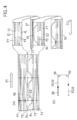
- FIG. 4A is a schematic plan view showing the middle stage of the manufacturing method of the worn article with a partial perspective
- FIG. 4B is a side view showing a turn roller that turns the transport direction.
- FIG. 5 is a schematic plan view showing a part of the latter stage of the manufacturing method of the worn article from a perspective view.
- the width D11 of the wide first split web W11 is smaller than the width D2 of the second continuous web W2, and the first split web W11 has first and second side edges along the transport direction. It has parts E1 and E2 Further provided is a folding step of bending each pair of third side edge portions E3 along the transport direction of the second continuous web W2 to wrap the first and second side edge portions E1 and E2 of the laminated sheet S.
- the side edges of the web are often bent at the upper end of each waistline.
- the width of the first continuous web W1 before the division becomes significantly large, and the equipment becomes bulky. Become.
- the second continuous web W2 is laminated on the first surface 31 of the first divided web W11.
- each of the third side edge portions E3 of the second continuous web W2 is bent so as to overlap the second surface 32 of the first divided web W11.
- the second split web W12 is bonded to the second surface 32 of the first split web W11.
- both the third side edge portion E3 of the second continuous web W2 and the edge of the second split web W12 appear on the second surface 32 of the first split web W11. Therefore, by setting the second surface 32 to the skin surface side, the appearance (texture) of the non-skin surface of the worn article is improved.
- the waistline elastic member FT is arranged on the first and second side edge portions E1 and E2 along the transport direction of the laminated sheet S.
- the leg elastic member FL is arranged in the central region between the first side edge portion E1 and the second side edge portion E2 of the laminated sheet S.
- the stretchable continuous sheet S0 is slit along a virtual second cutting line C2 along the transport direction to form a part of the leg elastic member FL, a part of the waist elastic member FT, and the first side edge.
- a second slit step for generating the two-divided sheet S2 is further provided.
- both the front waist circumference portion T1 and the rear waist circumference portion T2 can be generated from the two first and second continuous webs.
- an absorbent main body C that connects the front waist circumference portion T1 and the rear waist circumference portion T2 and serves as a crotch portion is intermittently erected between the first divided sheet S1 and the second divided sheet S2. Further erection process is provided.
- the leg elastic member FL is periodically arranged in a wavy shape.
- Another waistline elastic member F2 extending linearly along the transport direction is further sandwiched between the laminated sheet S and the narrow second divided web W12, and is joined by the adhesive to form the stretchable continuous sheet S0.
- Another waistline elastic member F2 extending linearly along the transport direction is further sandwiched between the laminated sheet S and the narrow second divided web W12, and is joined by the adhesive to form the stretchable continuous sheet S0.
- the first and second continuous webs W1 and W2 are formed of a thermoplastic resin.
- the welding step is performed by ultrasonic welding or heat sealing.
- each web may be a thermoplastic non-woven fabric in which a large number of thermoplastic fibers are laminated.
- the worn article 1 of this embodiment has a symmetrical shape and structure, and includes an absorbent main body C and front and rear waist circumferences T1 and T2.
- the front waist circumference portion T1 covers the front body of the wearer and extends in the waist circumference direction X.
- the rear waist circumference portion T2 covers the rear waist of the wearer and extends in the waist circumference direction X.
- the absorbent main body C is erected on both waist circumferences T1 and T2, and has a crotch portion 22 that covers the wearer's crotch.
- the absorbent body C extends in the vertical direction Y orthogonal to the waist circumference direction X.
- the absorbent body C constitutes part or all of the crotch 22.
- the worn article may be a pants-type worn article in which the ends of the front and rear waistline portions T1 and T2 in the waistline direction X are joined (sealed) so as to overlap each other.
- the absorbent body C is provided with an absorbent core (not shown). This absorption core absorbs body fluids.
- the absorption core is sandwiched between the top sheet and the back sheet. Each sheet and absorption core are laminated to each other.
- the top sheet consists of a thin, permeable non-woven fabric that covers the skin surface of the absorbent core.
- a cuff (not shown) may be provided on the top sheet.
- the back sheet covers the non-skin surface of the absorbent core and consists of a liquid-impermeable resin sheet.
- Each end portion of the absorbent body C in the vertical direction Y is attached to each waist circumference portion T1 and T2.
- the waist circumference portions T1 and T2 project from the absorbent main body C in the waist circumference direction X.
- the waist circumference portions T1 and T2 are provided with waist circumference and leg circumference elastic members FT, F2, and FL for fitting the worn article 1 to the wearer.
- the elastic member may be linear or cord-shaped.
- the elastic member may be a multi-strand in which a plurality of rubber threads (fibrous elastic bodies) are assembled in a bundle. Examples of the material of the rubber thread include polyurethane.
- the first waistline elastic member FT and the second (other) waistline elastic member F2 may be linear and extend in the waistline direction X in parallel with each other.
- the elastic members FT and F2 arranged in a straight line and in parallel may be invalidated (there is no contraction force) at the portion overlapping with the absorbent body C.
- the plurality of leg elastic members FL are arranged in a wavy shape parallel to each other and along the outline 10E at the lower ends of the waist circumference portions T1 and T2.
- the outline 10E at the lower end becomes the lower end when worn.
- the waist circumference portions T1 and T2 are formed of the telescopic sheet 10.
- the absorbent body C of FIG. 1A may be formed with a constricted portion (not shown) constricted along the wearer's crotch.
- the crotch portion 22 may be provided with another leg circumference elastic member made of, for example, thread rubber, along the leg circumference of the wearer.
- the absorbent main body C is attached to the skin surface of the waist circumferences T1 and T2.
- the "skin surface” refers to the surface facing the wearer's skin when the worn article 1 is worn
- the “non-skin surface” refers to the surface opposite to the skin surface.
- the stretchable sheet 10 of the worn article has a skin surface in contact with the wearer's skin and a non-skin surface on the opposite side.
- the telescopic sheet 10 has webs 11 and 12 for the first and second waist circumferences, webs 13 for the leg circumferences, and elastic members FT, F2, and FL laminated.
- the first waist circumference elastic member FT is welded and fixed between the first waist circumference web 11 and the second waist circumference web 12.
- the second waist circumference elastic member F2 and the leg circumference elastic member FL are adhered and fixed between the first waist circumference web 11 and the leg circumference web 13.
- a plurality of first waist elastic members FT are arranged between a pair of webs 11 and 12, and are arranged apart from each other as shown by a broken line in FIG. 1 (c).
- the elastic sheet 10 Due to the contraction force of each elastic member, the elastic sheet 10 forms a large number of folds in a state where each elastic member is contracted, and fits the wearer's skin.
- the first waist circumference elastic member FT of FIG. 1B is arranged between the non-skin surface, which is the first surface 31 of the first waist circumference web 11, and the second waist circumference web 12.
- the portion serving as the upper edge of the second waist circumference web 12 is folded back and adhered to the skin surface which is the second surface 32 of the first waist circumference web 11.
- the second waist elastic member 32 and the leg elastic member FL of FIG. 1 (b) are arranged between the pair of webs 11 and 13, and are separated from each other as shown by the broken line of FIG. 1 (c). ing.
- the second waist circumference elastic member 32 and the leg circumference elastic member FL are arranged between the skin surface, which is the second surface 32 of the first waist circumference web 11 of FIG. 1 (b), and the leg circumference web 13.
- the three webs 11 to 13 are laminated, so that the folded edge 12E of the second waistline web 12 and the upper edge 13E of the leg circumference web 13 do not appear on the non-skin surface of the worn article. , Looks good.
- the absorbent main body C in FIG. 1A is erected between the front waist circumference portion T1 and the rear waist circumference portion T2 so as to cover a part of the upper edge 13E of the leg circumference web 13. Therefore, the upper edge 13E of the leg circumference web 13 does not come into contact with the front and rear torso of the wearer, so that the skin feels good (feeling of wearing).
- FIGS. 3 to 5 the unit is indicated by a chain double-dashed line so that the unit of each worn article can be seen in the width direction orthogonal to the transport direction of the semi-finished product.
- the first and second continuous webs W1 and W2 are continuously transported in a predetermined transport direction (girth direction) X1.
- the first continuous web W1 is slit along a virtual first cutting line C1 extending in the transport direction X1 to divide the first continuous web W1 into a wide first split web W11 and a narrow second split web W12.
- One slit process is performed.
- the width D11 of the first split web W11 is larger than the width D12 of the second split web W12.
- the width D2 of the second continuous web W2 is larger than the width D11 of the first divided web W11.
- the first split web W11 in an extended state extending in the waist circumference direction X (conveyance direction X1) is sandwiched between the wide first split web W11 and the second continuous web W2, and the first split web W11 and the first split web W11 A welding step is executed in which the second continuous web W2 and the first waistline elastic member FT are intermittently welded in the transport direction X1 to form the laminated sheet S.
- both webs W11 and W2 and the first waistline elastic member FT are introduced between the ultrasonic horn 50 and the anvil roll 51.
- the horn 50 cooperates with the anvil roll 51 to ultrasonically weld a pair of webs W11 and W2 to each other, and weld a waist elastic member FT to the pair of webs to hold the waist elastic member FT by the pair of webs.
- the welding step may be performed by heat sealing instead of ultrasonic welding.
- the width D11 of the wide first split web W11 in FIG. 3A is smaller than the width D2 of the second continuous web W2, and the first split web W11 has first and second side edges along the transport direction X1. It has E1 and E2.
- a folding step of bending each pair of third side edge portions E3 along the transport direction X1 of the second continuous web W2 to wrap the first and second side edge portions E1 and E2 of the first divided web W11 is executed. To do.
- a plurality of second waist elastic members F2 and leg elastic members FL which are different from the first waist elastic member FT, are sandwiched and adhered between the laminated sheet S and the narrow second split web W12 in an extended state.
- An adhesive step of joining with an agent to produce an elastic continuous sheet S0 is performed.
- a plurality of second waistline elastic members F2 extend linearly along the transport direction X1 and parallel to each other.
- the leg elastic member FL extends along a predetermined waveform while meandering in the transport direction X1, and is arranged in a periodic, wavy shape as described later.
- the laminated sheet S and the second split web W12 are coated with an adhesive from the coating machine 52, and then the leg elastic member FL is applied to the laminated sheet. It is introduced between the pair of nip rolls 53, 53 in a state of being arranged between the S and the second split web W12.
- the introduction machine 54 guides the leg-rotating elastic member FL while repeatedly reciprocating in the axial direction of the nip rolls 53 and 53, and the leg-rotating elastic member FL extends while meandering in a predetermined wave shape as shown in FIG. 3A. Arranged like this.
- the first waist circumference elastic member FT is arranged at the first and second side edge portions E1 and E2 along the transport direction X1 of the laminated sheet S.
- the second waistline elastic member F2 and the leg circumference elastic member FL are located in the central region between the first side edge portion E1 and the second side edge portion E2 of the laminated sheet S. Is placed.
- the stretchable continuous sheet S0 of FIG. 4A is slit along the virtual second cutting line C2 along the transport direction X1 to generate the first and second divided sheets S1 and S2.
- the first divided sheet S1 is a front waist circumference portion T1 (FIG. 1 (c)) including a part of the leg circumference elastic member FL, a part of the waist circumference elastic members FT and F2, and the first side edge portion E1.
- the second split sheet S2 is a rear waist circumference portion T2 (FIG. 1 (c)) including the rest of the leg circumference elastic member FL, the rest of the waist circumference elastic members FT and F2, and the second side edge portion E2.
- the first elastic member FT and the second elastic member F2 of the stretchable continuous sheet S0 obtained by the welding and bonding steps described above have a region in which the absorbent body C (FIG. 5) is arranged. It may be invalidated by being disconnected or the like.
- the second continuous web W2 is laminated on the first surface 31 of the first divided web W11. Further, as shown in FIG. 2F, in the above-mentioned folding step, each third side edge portion E3 of the second continuous web W2 is bent so as to overlap the second surface 32 of the first divided web W11. On the other hand, as shown in FIG. 2 (g), in the above-mentioned bonding step, the second split web W12 is bonded to the second surface 32 of the first split web W11.
- a widening step of transporting the first and second split sheets S1 and S2 is executed so that the pair of split sheets S1 and S2 are separated from each other. As a result, the two divided sheets S1 and S2 are separated from each other.
- the two split sheets S1 and S2 may be turned by the turning roller 55 and conveyed upside down as shown in FIG. 4A, for example.
- the absorbent main body C to be the crotch portion 22 is intermittently erected between the first divided sheet S1 and the second divided sheet S2.
- the leg elastic member FL is periodically arranged in a wavy shape as described below.
- the leg elastic member FL arranged on the first divided sheet S1 and the leg elastic member FL arranged on the second divided sheet S2 of FIG. 4A.
- the leg elastic member FL and the second divided sheet S2 arranged on the first divided sheet S1 are arranged in a wavy shape so as to be separated from each other.
- the edge (outline 10E at the lower end) at the lower end when worn is trimmed to a shape along the curvature of the leg elastic member FL and is continuous.
- the laminated body S3 is generated. It should be noted that this trimming does not necessarily have to be performed.
- the laminated sheet S of FIG. 3A may be divided into two along a wavy cutting line, and the leg elastic member FL may be arranged along the corrugated shape. Further, the timing of trimming may be performed at any time as long as the expansion / contraction continuous sheet S0 is generated.
- the continuous laminate S3 is folded in two in the absorbent body C. After this folding step, the continuous laminated body S3 is cut at the virtual third cutting line C3 indicated by the alternate long and short dash line, and the first divided sheet S1 and the second divided sheet S2 are cut in the vicinity of the third cut line C3. And are welded together to form a so-called seal.
- this example is an example of a pants-type worn item, it may be a diaper-type worn item provided with a fastener or tape on the worn item of FIG. 1 (a).
- this worn item does not have to have a cuff or the like.
- the tension of the elastic member may be invalidated at a portion other than the portion that wraps with the absorbent main body in the waist circumference portion.
- the waist circumference portion does not have to be formed by being slit in two. Therefore, such changes and amendments are construed as being within the scope of the invention as defined by the claims.
- the present invention can be applied to various worn items such as pants type and diaper type.
Abstract
This method comprises: a step for conveying a first continuous web and a second continuous web in a prescribed conveying direction; a first slitting step for slitting the first continuous web along a first virtual cutting line extending in the conveying direction so as to divide said web into a first divided web having a wider width and a second divided web having a narrower width; a step for tucking down a girth elastic member extending in the girth direction between the wider first divided web and the second continuous web; a welding step for forming a laminated sheet by intermittently welding the first divided web, the second continuous web, and the girth elastic member in the conveying direction; and a bonding step for forming a stretchable continuous sheet by tucking down and bonding, with an adhesive, a leg-wrapping elastic member, which extends in the conveying direction in a meandering fashion, between the laminated sheet and the narrower second divided web.
Description
本発明は着用物品の製造方法に係り、より詳しくは使い捨てオムツやパンツの胴回り部となる伸縮シートの製造方法に関する。
The present invention relates to a method for manufacturing a worn article, and more particularly to a method for manufacturing an elastic sheet to be a waistline of disposable diapers and pants.
この種の伸縮シートには、胴体の周囲に沿って互いに平行に配置される胴回り弾性部材と、脚の付け根に沿って湾曲して配置される脚回り弾性部材とが設けられるのが望ましい。
胴回り弾性部材は胴体の周囲に平行に配置されていることで、伸縮シートを胴体にフィットさせる。一方、脚回り弾性部材は脚の付け根に沿って湾曲して配置されていることで、尿漏れなどを防止する。 It is desirable that this type of telescopic sheet is provided with a waist elastic member arranged parallel to each other along the circumference of the body and a leg elastic member curved along the base of the leg.
The elastic member around the waist is arranged parallel to the circumference of the body to fit the elastic sheet to the body. On the other hand, the elastic members around the legs are arranged so as to be curved along the base of the legs to prevent urine leakage and the like.
弾性部材を互いに平行に配置する方法として、2枚の連続ウェブの間に伸張状態の弾性部材を挟み込み連続ウェブの搬送方向(長手方向)に間欠的に3者を溶着する方法が提案されている。(特許文献1)
As a method of arranging the elastic members in parallel with each other, a method of sandwiching an elastic member in a stretched state between two continuous webs and intermittently welding the three in the transport direction (longitudinal direction) of the continuous webs has been proposed. .. (Patent Document 1)
この先行技術において、弾性部材とウェブとを溶着する場合、溶着加工時に弾性部材が切断されないように、溶着装置のアンビルに形成した溝に弾性部材を案内する必要がある。したがって、ウェブに溶着する弾性部材は、搬送方向に平行な直線的に配置せざるを得ず、湾曲した軌跡で配置することは、困難である。
In this prior art, when the elastic member and the web are welded, it is necessary to guide the elastic member to the groove formed in the anvil of the welding device so that the elastic member is not cut during the welding process. Therefore, the elastic member welded to the web has to be arranged in a straight line parallel to the transport direction, and it is difficult to arrange it in a curved locus.
このようなことから、前記直線的に配置された弾性部材と湾曲した弾性部材の配置工程とは別工程となる。そのため、弾性部材を挟み込むウェブが少なくとも3枚必要となり、原反コストが高くなるとともに、その原反を送り出したり、継ぐ装置も増加し、設備コストもアップする。
For this reason, the process of arranging the linearly arranged elastic member and the curved elastic member is a separate process. Therefore, at least three webs for sandwiching the elastic member are required, which increases the cost of the raw fabric, increases the number of devices for sending and connecting the raw fabric, and increases the equipment cost.
したがって、本発明の目的は、胴回りおよび脚回り弾性部材を有する着用物品について、原反コストや設備コストの安い製造方法を提供することである。
Therefore, an object of the present invention is to provide a manufacturing method having a low raw fabric cost and low equipment cost for a worn article having elastic members around the waist and legs.
本発明の着用物品の製造方法は第1および第2連続ウェブW1,W2を所定の搬送方向に搬送する工程と、
前記第1連続ウェブW1を前記搬送方向に延びる仮想の第1切断線C1に沿ってスリットして、幅広の第1分割ウェブW11と幅狭の第2分割ウェブW12に分割する第1スリット工程と、
幅広の前記第1分割ウェブW11と前記第2連続ウェブW2との間に胴回り方向に延びる胴回り弾性部材FTを挟み込む工程と、
前記第1分割ウェブW11と前記第2連続ウェブW2と前記胴回り弾性部材FTとを前記搬送方向に間欠的に溶着して積層シートSを生成する溶着工程と、
前記積層シートSと幅狭の前記第2分割ウェブW12との間に前記搬送方向に対して蛇行しながら延びる脚回り弾性部材FLを挟み込むと共に接着剤により接合して伸縮連続シートS0を生成する接着工程とを備える。 The method for manufacturing a worn article of the present invention includes a step of transporting the first and second continuous webs W1 and W2 in a predetermined transport direction, and
A first slit step of slitting the first continuous web W1 along a virtual first cutting line C1 extending in the transport direction to divide the first continuous web W1 into a wide first split web W11 and a narrow second split web W12. ,
A step of sandwiching a waist elastic member FT extending in the waist direction between the wide first split web W11 and the second continuous web W2,
A welding step of intermittently welding the first divided web W11, the second continuous web W2, and the waistline elastic member FT in the transport direction to form a laminated sheet S.
Adhesion that sandwiches the leg circumference elastic member FL that extends while meandering in the transport direction between the laminated sheet S and the narrow second divided web W12 and joins them with an adhesive to generate an elastic continuous sheet S0. It has a process.
本発明によれば、胴回り弾性部材FTを挟むための第1分割ウェブW11と脚回り弾性部材FLを挟むための第2分割ウェブW12とが、1つの第1連続ウェブW1をスリットして得られる。そのため、連続ウェブの原反の数を1つ減らすことができる。したがって、原反自体のコストや原反を掛け替えたり、継いだりする装置に関するコストも安価になる。
According to the present invention, the first divided web W11 for sandwiching the waist elastic member FT and the second divided web W12 for sandwiching the leg elastic member FL are obtained by slitting one first continuous web W1. .. Therefore, the number of raw fabrics of the continuous web can be reduced by one. Therefore, the cost of the original fabric itself and the cost of the device for replacing or succeeding the original fabric are also reduced.
前記胴回り弾性部材FTは第1分割ウェブW11と第2連続ウェブW2との間に挟まれて、これらに溶着される。そのため、伸縮連続シートS0にゴワツキが生じにくい。
The waistline elastic member FT is sandwiched between the first split web W11 and the second continuous web W2 and welded to them. Therefore, the stretchable continuous sheet S0 is less likely to be stiff.
一方、脚回り弾性部材FLは第2分割ウェブW12と積層シートSとの間に挟まれて、これらに接着剤により接着される。そのため、脚の付け根に沿って湾曲した波形状に脚回り弾性部材FLを配置することができる。
On the other hand, the leg elastic member FL is sandwiched between the second split web W12 and the laminated sheet S, and is adhered to these by an adhesive. Therefore, the leg elastic member FL can be arranged in a wave shape curved along the base of the leg.
本発明において、搬送方向とはウェブやシートが長手方向に沿って搬送される長手方向を意味し、当該搬送方向はウェブやシートが転向(ターン)されることで変化する。
In the present invention, the transport direction means the longitudinal direction in which the web or the sheet is transported along the longitudinal direction, and the transport direction changes when the web or the sheet is turned.
本発明において好ましくは、幅広の前記第1分割ウェブW11の幅D11は前記第2連続ウェブW2の幅D2よりも小さく、前記第1分割ウェブW11は搬送方向に沿った第1および第2側縁部E1,E2を有し、
前記第2連続ウェブW2の搬送方向に沿った一対の各第3側縁部E3を折り曲げて前記積層シートSの第1および第2側縁部E1,E2を包む折り返し工程を更に備える。 In the present invention, preferably, the width D11 of the wide first split web W11 is smaller than the width D2 of the second continuous web W2, and the first split web W11 has first and second side edges along the transport direction. It has parts E1 and E2
Further provided is a folding step of bending each pair of third side edge portions E3 along the transport direction of the second continuous web W2 to wrap the first and second side edge portions E1 and E2 of the laminated sheet S.
着用物品の見栄えを良くするために、各胴回り部の上端の部位は、ウェブの側縁部が折り曲げられる場合が多い。ここで、第1連続ウェブW1を分割して得られた第1分割ウェブW11の側縁部を折り曲げるようにした場合、分割前の第1連続ウェブW1の幅が著しく大きくなり、設備が嵩高くなる。
In order to improve the appearance of the worn items, the side edges of the web are often bent at the upper end of each waistline. Here, when the side edge portion of the first divided web W11 obtained by dividing the first continuous web W1 is bent, the width of the first continuous web W1 before the division becomes significantly large, and the equipment becomes bulky. Become.
これに対し、本例では第2連続ウェブW2の各第3側縁部E3を折り曲げるので、分割前の第1連続ウェブW1の幅が著しく大きくなるのを抑制できる。
On the other hand, in this example, since each third side edge E3 of the second continuous web W2 is bent, it is possible to prevent the width of the first continuous web W1 before division from becoming significantly large.
より好ましくは、前記溶着工程において、前記第1分割ウェブW11の第1面31に前記第2連続ウェブW2が積層され、
前記折り返し工程において、前記第2連続ウェブW2の前記各第3側縁部E3が前記第1分割ウェブW11の第2面32に重なるように折り曲げられ、
前記接着工程において、前記第1分割ウェブW11の前記第2面32に前記第2分割ウェブW12が接着される。 More preferably, in the welding step, the second continuous web W2 is laminated on thefirst surface 31 of the first divided web W11.
In the folding step, each of the third side edge portions E3 of the second continuous web W2 is bent so as to overlap thesecond surface 32 of the first divided web W11.
In the bonding step, the second split web W12 is bonded to thesecond surface 32 of the first split web W11.
前記折り返し工程において、前記第2連続ウェブW2の前記各第3側縁部E3が前記第1分割ウェブW11の第2面32に重なるように折り曲げられ、
前記接着工程において、前記第1分割ウェブW11の前記第2面32に前記第2分割ウェブW12が接着される。 More preferably, in the welding step, the second continuous web W2 is laminated on the
In the folding step, each of the third side edge portions E3 of the second continuous web W2 is bent so as to overlap the
In the bonding step, the second split web W12 is bonded to the
この場合、第2連続ウェブW2の第3側縁部E3および第2分割ウェブW12の縁の双方が第1分割ウェブW11の第2面32に表われる。そのため、第2面32を肌面側に設定することで、着用物品の非肌面の見栄え(風合い)が向上する。
In this case, both the third side edge portion E3 of the second continuous web W2 and the edge of the second split web W12 appear on the second surface 32 of the first split web W11. Therefore, by setting the second surface 32 to the skin surface side, the appearance (texture) of the non-skin surface of the worn article is improved.
好ましくは、前記溶着工程において前記積層シートSの搬送方向に沿った第1および第2側縁部E1,E2に前記胴回り弾性部材FTが配置され、
前記伸縮連続シートS0を生成する接着工程において、前記積層シートSの前記第1側縁部E1と前記第2側縁部E2との間の中央領域に前記脚回り弾性部材FLが配置され、
前記伸縮連続シートS0を前記搬送方向に沿った仮想の第2切断線C2に沿ってスリットして、前記脚回り弾性部材FLの一部、前記胴回り弾性部材FTの一部および前記第1側縁部E1を含む前胴回り部T1となる第1分割シートS1と、前記脚回り弾性部材FLの残部、前記胴回り弾性部材FTの残部および前記第2側縁部E2を含む後胴回り部T2となる第2分割シートS2とを生成する第2スリット工程を更に備える。 Preferably, in the welding step, the waistline elastic member FT is arranged on the first and second side edge portions E1 and E2 along the transport direction of the laminated sheet S.
In the bonding step of producing the stretchable continuous sheet S0, the leg elastic member FL is arranged in the central region between the first side edge portion E1 and the second side edge portion E2 of the laminated sheet S.
The stretchable continuous sheet S0 is slit along a virtual second cutting line C2 along the transport direction to form a part of the leg elastic member FL, a part of the waist elastic member FT, and the first side edge. A first divided sheet S1 to be a front waist circumference portion T1 including a portion E1, a second portion to be a rear waist circumference portion T2 including the remaining portion of the leg circumference elastic member FL, the remainder of the waist circumference elastic member FT, and the second side edge portion E2. A second slit step for generating the two-divided sheet S2 is further provided.
この場合、2枚の第1および第2連続ウェブから前胴回り部T1および後胴回り部T2の双方を生成することができる。
In this case, both the front waist circumference portion T1 and the rear waist circumference portion T2 can be generated from the two first and second continuous webs.
好ましくは、前記前胴回り部T1と前記後胴回り部T2との間を連ね股部となる吸収性本体Cが前記第1分割シートS1と前記第2分割シートS2との間に間欠的に架設される架設工程を更に備える。
Preferably, an absorbent main body C that connects the front waist circumference portion T1 and the rear waist circumference portion T2 and serves as a crotch portion is intermittently erected between the first divided sheet S1 and the second divided sheet S2. Further erection process is provided.
更に好ましくは、前記吸収性本体Cが架設された部位において、前記第1分割シートS1に配置された前記脚回り弾性部材FLと前記第2分割シートS2に配置された前記脚回り弾性部材FLとが互いに接近するように、かつ、互いに隣り合う前記吸収性本体Cの間の部位において、前記第1分割シートS1に配置された前記脚回り弾性部材FLと前記第2分割シートS2に配置された前記脚回り弾性部材FLとが互いに遠ざかるように、
前記伸縮連続シートS0を生成する接着工程において前記脚回り弾性部材FLが周期的に波形状に配置される。 More preferably, at the portion where the absorbent main body C is erected, the leg elastic member FL arranged on the first divided sheet S1 and the leg elastic member FL arranged on the second divided sheet S2. Are arranged on the leg-rotating elastic member FL and the second divided sheet S2 arranged on the first divided sheet S1 at a portion between the absorbent main bodies C adjacent to each other so as to approach each other. So that the elastic members FL around the legs are separated from each other.
In the bonding step of producing the stretchable continuous sheet S0, the leg elastic member FL is periodically arranged in a wavy shape.
この場合、脚の付け根に沿って脚周り弾性部材FLが配置された着用物品が得られる。
In this case, a worn article in which the elastic member FL around the leg is arranged along the base of the leg is obtained.
好ましくは、前記伸縮連続シートS0を生成する接着工程において、
前記積層シートSと幅狭の前記第2分割ウェブW12との間に前記搬送方向に沿って直線状に延びる別の胴回り弾性部材F2を更に挟み込むと共に前記接着剤により接合して前記伸縮連続シートS0を生成する。 Preferably, in the bonding step of producing the stretchable continuous sheet S0,
Another waistline elastic member F2 extending linearly along the transport direction is further sandwiched between the laminated sheet S and the narrow second divided web W12, and is joined by the adhesive to form the stretchable continuous sheet S0. To generate.
この場合、脚回りに近い胴回りの下部に前記別の弾性部材F2が配置されることで、胴回り部のフィット性能が高まる。
In this case, by arranging the other elastic member F2 in the lower part of the waistline close to the leg circumference, the fitting performance of the waistline portion is improved.
好ましくは、前記第1および第2連続ウェブW1,W2が熱可塑性樹脂で形成され、
前記溶着工程が超音波溶着またはヒートシールで実行される。 Preferably, the first and second continuous webs W1 and W2 are formed of a thermoplastic resin.
The welding step is performed by ultrasonic welding or heat sealing.
前記溶着工程が超音波溶着またはヒートシールで実行される。 Preferably, the first and second continuous webs W1 and W2 are formed of a thermoplastic resin.
The welding step is performed by ultrasonic welding or heat sealing.
熱可塑性の第1および第2ウェブは弾性部材と溶着され易い。
なお、各ウェブは多数の熱可塑性の繊維が積層された熱可塑性の不織布であってもよい。 The thermoplastic first and second webs are easily welded to the elastic member.
In addition, each web may be a thermoplastic non-woven fabric in which a large number of thermoplastic fibers are laminated.
なお、各ウェブは多数の熱可塑性の繊維が積層された熱可塑性の不織布であってもよい。 The thermoplastic first and second webs are easily welded to the elastic member.
In addition, each web may be a thermoplastic non-woven fabric in which a large number of thermoplastic fibers are laminated.
1つの前記各実施態様または下記の実施例に関連して説明/およびまたは図示した特徴は、1つまたはそれ以上の他の実施態様または他の実施例において同一または類似な形で、および/または他の実施態様または実施例の特徴と組み合わせて、または、その代わりに利用することができる。
The features described / and / or illustrated in connection with each of the above embodiments or the following embodiments are the same or similar in one or more other embodiments or other embodiments, and / or It can be used in combination with or in place of features of other embodiments or examples.
本発明は、添付の図面を参考にした以下の好適な実施例の説明からより明瞭に理解されるであろう。しかし、実施例および図面は単なる図示および説明のためのものであり、本発明の範囲を定めるために利用されるべきものではない。本発明の範囲は請求の範囲によってのみ定まる。添付図面において、複数の図面における同一の部品番号は、同一または相当部分を示す。
The present invention will be more clearly understood from the following description of preferred embodiments with reference to the accompanying drawings. However, the examples and drawings are for illustration and illustration purposes only and should not be used to define the scope of the invention. The scope of the present invention is determined only by the claims. In the accompanying drawings, the same part number in a plurality of drawings indicates the same or equivalent part.
まず、本発明の製造方法の説明に先立って着用物品1の構造の一例が図面にしたがって説明される。なお、各図は弾性部材が伸張した状態で図示されている。
First, an example of the structure of the worn article 1 will be described with reference to the drawings prior to the description of the manufacturing method of the present invention. In addition, each figure is shown in the state where the elastic member is stretched.
図1(a)および(b)に示すように、本実施例の着用物品1は、左右対称の形状および構造を有し、吸収性本体Cおよび前後の胴回り部T1,T2を備えている。前胴回り部T1は着用者の前胴を覆い胴回り方向Xに延びる。後胴回り部T2は着用者の後胴を覆い胴回り方向Xに延びる。吸収性本体Cは両胴回り部T1,T2に架設され、着用者の股間を覆う股部22を有している。
As shown in FIGS. 1A and 1B, the worn article 1 of this embodiment has a symmetrical shape and structure, and includes an absorbent main body C and front and rear waist circumferences T1 and T2. The front waist circumference portion T1 covers the front body of the wearer and extends in the waist circumference direction X. The rear waist circumference portion T2 covers the rear waist of the wearer and extends in the waist circumference direction X. The absorbent main body C is erected on both waist circumferences T1 and T2, and has a crotch portion 22 that covers the wearer's crotch.
吸収性本体Cは前記胴回り方向Xに直交する縦方向Yに延びる。吸収性本体Cは股部22の一部又は全部を構成する。
The absorbent body C extends in the vertical direction Y orthogonal to the waist circumference direction X. The absorbent body C constitutes part or all of the crotch 22.
図示していないが、完成品の状態では、股部22は胴回り方向Xに平行なラインにおいて2つに折られている。これにより、着用物品は、前後の胴回り部T1,T2の胴回り方向Xの端部同士が互いに重なった状態で接合(シール)されたパンツ型の着用物品であってもよい。
Although not shown, in the finished product state, the crotch portion 22 is folded in two at a line parallel to the waist circumference direction X. As a result, the worn article may be a pants-type worn article in which the ends of the front and rear waistline portions T1 and T2 in the waistline direction X are joined (sealed) so as to overlap each other.
吸収性本体Cには図示しない吸収コアが設けられている。この吸収コアは体液を吸収する。吸収コアは、トップシートとバックシートとの間で挟まれている。各シートおよび吸収コアは互いに積層されている。
The absorbent body C is provided with an absorbent core (not shown). This absorption core absorbs body fluids. The absorption core is sandwiched between the top sheet and the back sheet. Each sheet and absorption core are laminated to each other.
トップシートは透液性の薄い不織布からなり、吸収コアの肌面を覆う。このトップシートの上には、図示しないカフが設けられていてもよい。
The top sheet consists of a thin, permeable non-woven fabric that covers the skin surface of the absorbent core. A cuff (not shown) may be provided on the top sheet.
バックシートは吸収コアの非肌面を覆い、液不透過性の樹脂シートからなる。吸収性本体Cの前記縦方向Yの各端部は、各胴回り部T1,T2に貼り付けられている。各胴回り部T1,T2は、吸収性本体Cから胴回り方向Xに突出している。
The back sheet covers the non-skin surface of the absorbent core and consists of a liquid-impermeable resin sheet. Each end portion of the absorbent body C in the vertical direction Y is attached to each waist circumference portion T1 and T2. The waist circumference portions T1 and T2 project from the absorbent main body C in the waist circumference direction X.
図1(c)に明示するように、各胴回り部T1,T2には、着用物品1を着用者にフィットさせるための胴回りおよび脚回り弾性部材FT,F2,FLが設けられている。弾性部材は、線状または索状であってもよい。例えば、弾性部材は、複数の糸ゴム(繊維状弾性体)が束状に集合したマルチストランドであってもよい。糸ゴムの材質としては、例えば、ポリウレタンが挙げられる。
As is clearly shown in FIG. 1 (c), the waist circumference portions T1 and T2 are provided with waist circumference and leg circumference elastic members FT, F2, and FL for fitting the worn article 1 to the wearer. The elastic member may be linear or cord-shaped. For example, the elastic member may be a multi-strand in which a plurality of rubber threads (fibrous elastic bodies) are assembled in a bundle. Examples of the material of the rubber thread include polyurethane.
第1胴回り弾性部材FTおよび第2(別の)胴回り弾性部材F2は直線状で互いに平行に胴回り方向Xに延びていてもよい。直線状かつ平行に配置された弾性部材FT,F2は吸収性本体Cと重なる部分において、無効化され(収縮力がない状態とされ)ていてもよい。
The first waistline elastic member FT and the second (other) waistline elastic member F2 may be linear and extend in the waistline direction X in parallel with each other. The elastic members FT and F2 arranged in a straight line and in parallel may be invalidated (there is no contraction force) at the portion overlapping with the absorbent body C.
図1(c)に明示するように、複数本の脚回り弾性部材FLは、互いに平行に、かつ、各胴回り部T1,T2の下端のアウトライン10Eに沿って波形状に配置されている。下端のアウトライン10Eは着用時に下端となる。
なお、各胴回り部T1,T2は伸縮シート10で形成されている。 As is clearly shown in FIG. 1 (c), the plurality of leg elastic members FL are arranged in a wavy shape parallel to each other and along theoutline 10E at the lower ends of the waist circumference portions T1 and T2. The outline 10E at the lower end becomes the lower end when worn.
The waist circumference portions T1 and T2 are formed of thetelescopic sheet 10.
なお、各胴回り部T1,T2は伸縮シート10で形成されている。 As is clearly shown in FIG. 1 (c), the plurality of leg elastic members FL are arranged in a wavy shape parallel to each other and along the
The waist circumference portions T1 and T2 are formed of the
図1(a)の吸収性本体Cには、着用者の股に沿って括れた括れ部(図示せず)が形成されてもよい。股部22には、着用者の脚回りに沿うように、たとえば、糸ゴムなどからなる別の脚回り弾性部材が設けられていてもよい。
The absorbent body C of FIG. 1A may be formed with a constricted portion (not shown) constricted along the wearer's crotch. The crotch portion 22 may be provided with another leg circumference elastic member made of, for example, thread rubber, along the leg circumference of the wearer.
吸収性本体Cは胴回り部T1,T2の肌面に付着されている。
本明細書において、「肌面」とは着用物品1の着用時において着用者の肌に対面する側の面をいい、「非肌面」とは肌面とは反対の面をいう。 The absorbent main body C is attached to the skin surface of the waist circumferences T1 and T2.
In the present specification, the "skin surface" refers to the surface facing the wearer's skin when theworn article 1 is worn, and the "non-skin surface" refers to the surface opposite to the skin surface.
本明細書において、「肌面」とは着用物品1の着用時において着用者の肌に対面する側の面をいい、「非肌面」とは肌面とは反対の面をいう。 The absorbent main body C is attached to the skin surface of the waist circumferences T1 and T2.
In the present specification, the "skin surface" refers to the surface facing the wearer's skin when the
つぎに、伸縮シート10で形成された胴回り部T1,T2の詳細が説明される。
着用物品の伸縮シート10は着用者の肌に接する肌面と、その反対側の非肌面とを有する。 Next, the details of the waist circumference portions T1 and T2 formed of thetelescopic sheet 10 will be described.
Thestretchable sheet 10 of the worn article has a skin surface in contact with the wearer's skin and a non-skin surface on the opposite side.
着用物品の伸縮シート10は着用者の肌に接する肌面と、その反対側の非肌面とを有する。 Next, the details of the waist circumference portions T1 and T2 formed of the
The
伸縮シート10は第1および第2胴回り用のウェブ11,12と、脚回り用のウェブ13と、弾性部材FT,F2,FLとが積層されている。第1胴回りウェブ11と第2胴回りウェブ12との間に第1胴回り弾性部材FTが溶着されて固定されている。一方、第1胴回りウェブ11と脚回りウェブ13との間に第2胴回り弾性部材F2および脚回り弾性部材FLが接着剤により接着されて固定されている。
The telescopic sheet 10 has webs 11 and 12 for the first and second waist circumferences, webs 13 for the leg circumferences, and elastic members FT, F2, and FL laminated. The first waist circumference elastic member FT is welded and fixed between the first waist circumference web 11 and the second waist circumference web 12. On the other hand, the second waist circumference elastic member F2 and the leg circumference elastic member FL are adhered and fixed between the first waist circumference web 11 and the leg circumference web 13.
複数本の第1胴回り弾性部材FTは一対のウェブ11,12の間に配置され、かつ、図1(c)の破線で示すように互いに離間して配置されている。
A plurality of first waist elastic members FT are arranged between a pair of webs 11 and 12, and are arranged apart from each other as shown by a broken line in FIG. 1 (c).
各弾性部材の収縮力により、伸縮シート10は各弾性部材が収縮した状態で多数の襞を形成し、着用者の肌にフィットする。図1(b)の第1胴回り弾性部材FTは第1胴回り用ウェブ11の第1面31である非肌面と第2胴回りウェブ12との間に配置されている。第2胴回りウェブ12の上縁となる部位は第1胴回り用ウェブ11の第2面32である肌面に折り返されて接着されている。
Due to the contraction force of each elastic member, the elastic sheet 10 forms a large number of folds in a state where each elastic member is contracted, and fits the wearer's skin. The first waist circumference elastic member FT of FIG. 1B is arranged between the non-skin surface, which is the first surface 31 of the first waist circumference web 11, and the second waist circumference web 12. The portion serving as the upper edge of the second waist circumference web 12 is folded back and adhered to the skin surface which is the second surface 32 of the first waist circumference web 11.
図1(b)の前記第2胴回り弾性部材32および脚回り弾性部材FLは、前記一対のウェブ11,13の間に配置され、かつ、図1(c)の破線で示すように互いに離間している。第2胴回り弾性部材32および脚回り弾性部材FLは図1(b)の第1胴回り用ウェブ11の第2面32である肌面と脚回りウェブ13との間に配置されている。
The second waist elastic member 32 and the leg elastic member FL of FIG. 1 (b) are arranged between the pair of webs 11 and 13, and are separated from each other as shown by the broken line of FIG. 1 (c). ing. The second waist circumference elastic member 32 and the leg circumference elastic member FL are arranged between the skin surface, which is the second surface 32 of the first waist circumference web 11 of FIG. 1 (b), and the leg circumference web 13.
このように前記3枚のウェブ11~13が積層されており、そのため、着用物品の非肌面には第2胴回りウェブ12の折り返した縁12Eや脚回りウェブ13の上縁13Eが表われず、見栄えが良い。
In this way, the three webs 11 to 13 are laminated, so that the folded edge 12E of the second waistline web 12 and the upper edge 13E of the leg circumference web 13 do not appear on the non-skin surface of the worn article. , Looks good.
一方、図1(a)の吸収性本体Cは脚回りウェブ13の上縁13Eの一部を覆うように、前胴回り部T1と後胴回り部T2との間に架設されている。そのため、脚回りウェブ13の上縁13Eが着用者の前後の胴に接触しないから、肌当り(着用感)が良い。
On the other hand, the absorbent main body C in FIG. 1A is erected between the front waist circumference portion T1 and the rear waist circumference portion T2 so as to cover a part of the upper edge 13E of the leg circumference web 13. Therefore, the upper edge 13E of the leg circumference web 13 does not come into contact with the front and rear torso of the wearer, so that the skin feels good (feeling of wearing).
つぎに、着用物品の製造方法の一例が図2~図5を用いて説明される。
なお、図3~図5において、半製品の搬送方向に直交する幅方向に個々の着用物品の単位が分かるように、当該単位を二点鎖線で示している。 Next, an example of a method for manufacturing a worn article will be described with reference to FIGS. 2 to 5.
In addition, in FIGS. 3 to 5, the unit is indicated by a chain double-dashed line so that the unit of each worn article can be seen in the width direction orthogonal to the transport direction of the semi-finished product.
図3(a)に示すように、まず、第1および第2連続ウェブW1,W2を所定の搬送方向(胴回り方向)X1に連続搬送する。この搬送中に、第1連続ウェブW1を搬送方向X1に延びる仮想の第1切断線C1に沿ってスリットして、幅広の第1分割ウェブW11と幅狭の第2分割ウェブW12に分割する第1スリット工程が実行される。この第1分割ウェブW11の幅D11は第2分割ウェブW12の幅D12よりも大きい。また、第2連続ウェブW2の幅D2は第1分割ウェブW11の幅D11よりも大きい。
As shown in FIG. 3A, first, the first and second continuous webs W1 and W2 are continuously transported in a predetermined transport direction (girth direction) X1. During this transport, the first continuous web W1 is slit along a virtual first cutting line C1 extending in the transport direction X1 to divide the first continuous web W1 into a wide first split web W11 and a narrow second split web W12. One slit process is performed. The width D11 of the first split web W11 is larger than the width D12 of the second split web W12. Further, the width D2 of the second continuous web W2 is larger than the width D11 of the first divided web W11.
幅広の前記第1分割ウェブW11と第2連続ウェブW2との間には、胴回り方向X(搬送方向X1)に延びる伸長状態の第1胴回り弾性部材FTが挟み込まれると共に、第1分割ウェブW11と第2連続ウェブW2と第1胴回り弾性部材FTとが搬送方向X1に間欠的に溶着されて積層シートSを生成する溶着工程が実行される。
The first split web W11 in an extended state extending in the waist circumference direction X (conveyance direction X1) is sandwiched between the wide first split web W11 and the second continuous web W2, and the first split web W11 and the first split web W11 A welding step is executed in which the second continuous web W2 and the first waistline elastic member FT are intermittently welded in the transport direction X1 to form the laminated sheet S.
図3(b)に示すように、両ウェブW11,W2と第1胴回り弾性部材FTは、超音波ホーン50とアンビルロール51との間に導入される。前記ホーン50はアンビルロール51と協働して一対のウェブW11,W2を互いに超音波溶着すると共に一対のウェブに胴回り弾性部材FTを溶着して一対のウェブで胴回り弾性部材FTを保持させる。なお、超音波溶着に代えてヒートシールで溶着工程を実行しても良い。
As shown in FIG. 3B, both webs W11 and W2 and the first waistline elastic member FT are introduced between the ultrasonic horn 50 and the anvil roll 51. The horn 50 cooperates with the anvil roll 51 to ultrasonically weld a pair of webs W11 and W2 to each other, and weld a waist elastic member FT to the pair of webs to hold the waist elastic member FT by the pair of webs. The welding step may be performed by heat sealing instead of ultrasonic welding.
図3(a)の幅広の前記第1分割ウェブW11の幅D11は第2連続ウェブW2の幅D2よりも小さく、第1分割ウェブW11は搬送方向X1に沿った第1および第2側縁部E1,E2を有する。
溶着工程後に第2連続ウェブW2の搬送方向X1に沿った一対の各第3側縁部E3を折り曲げて第1分割ウェブW11の第1および第2側縁部E1,E2を包む折り返し工程を実行する。 The width D11 of the wide first split web W11 in FIG. 3A is smaller than the width D2 of the second continuous web W2, and the first split web W11 has first and second side edges along the transport direction X1. It has E1 and E2.
After the welding step, a folding step of bending each pair of third side edge portions E3 along the transport direction X1 of the second continuous web W2 to wrap the first and second side edge portions E1 and E2 of the first divided web W11 is executed. To do.
一方、積層シートSと幅狭の第2分割ウェブW12との間に第1胴回り弾性部材FTとは別の複数本の第2胴回り弾性部材F2および脚回り弾性部材FLを伸長状態で挟み込むと共に接着剤により接合して伸縮連続シートS0を生成する接着工程を実行する。
On the other hand, a plurality of second waist elastic members F2 and leg elastic members FL, which are different from the first waist elastic member FT, are sandwiched and adhered between the laminated sheet S and the narrow second split web W12 in an extended state. An adhesive step of joining with an agent to produce an elastic continuous sheet S0 is performed.
複数本の第2胴回り弾性部材F2は搬送方向X1に沿って直線状に、かつ、互いに平行に延びる。一方、脚回り弾性部材FLは搬送方向X1に対して蛇行しながら所定の波形に沿って延び、後述するように、周期的な、波形状に配置される。
A plurality of second waistline elastic members F2 extend linearly along the transport direction X1 and parallel to each other. On the other hand, the leg elastic member FL extends along a predetermined waveform while meandering in the transport direction X1, and is arranged in a periodic, wavy shape as described later.
図3(c)に示すように、前述の接着工程に先立って、積層シートSおよび第2分割ウェブW12には、塗布機52から接着剤が塗布され、その後、脚回り弾性部材FLが積層シートSと第2分割ウェブW12との間に配置された状態で一対のニップロール53,53の間に導入される。導入機54はニップロール53,53の軸方向に繰り返し往復移動しながら脚回り弾性部材FLを案内して、脚回り弾性部材FLが図3(a)のように所定の波形状に蛇行しながら延びるように配置される。
As shown in FIG. 3C, prior to the above-mentioned bonding step, the laminated sheet S and the second split web W12 are coated with an adhesive from the coating machine 52, and then the leg elastic member FL is applied to the laminated sheet. It is introduced between the pair of nip rolls 53, 53 in a state of being arranged between the S and the second split web W12. The introduction machine 54 guides the leg-rotating elastic member FL while repeatedly reciprocating in the axial direction of the nip rolls 53 and 53, and the leg-rotating elastic member FL extends while meandering in a predetermined wave shape as shown in FIG. 3A. Arranged like this.
図3の前述の溶着工程においては積層シートSの搬送方向X1に沿った第1および第2側縁部E1,E2に第1胴回り弾性部材FTが配置される。一方、伸縮連続シートS0を生成する接着工程においては、積層シートSの第1側縁部E1と第2側縁部E2との間の中央領域に第2胴回り弾性部材F2および脚回り弾性部材FLが配置される。
In the above-mentioned welding step of FIG. 3, the first waist circumference elastic member FT is arranged at the first and second side edge portions E1 and E2 along the transport direction X1 of the laminated sheet S. On the other hand, in the bonding step of producing the stretchable continuous sheet S0, the second waistline elastic member F2 and the leg circumference elastic member FL are located in the central region between the first side edge portion E1 and the second side edge portion E2 of the laminated sheet S. Is placed.
接着工程後、図4(a)の伸縮連続シートS0を搬送方向X1に沿った仮想の第2切断線C2に沿ってスリットして、第1および第2分割シートS1,S2を生成する第2スリット工程を実行する。第1分割シートS1は脚回り弾性部材FLの一部、胴回り弾性部材FT,F2の一部および第1側縁部E1を含む前胴回り部T1(図1(c))となる。一方、第2分割シートS2は脚回り弾性部材FLの残部、胴回り弾性部材FT,F2の残部および第2側縁部E2を含む後胴回り部T2(図1(c))となる。
After the bonding step, the stretchable continuous sheet S0 of FIG. 4A is slit along the virtual second cutting line C2 along the transport direction X1 to generate the first and second divided sheets S1 and S2. Perform the slit process. The first divided sheet S1 is a front waist circumference portion T1 (FIG. 1 (c)) including a part of the leg circumference elastic member FL, a part of the waist circumference elastic members FT and F2, and the first side edge portion E1. On the other hand, the second split sheet S2 is a rear waist circumference portion T2 (FIG. 1 (c)) including the rest of the leg circumference elastic member FL, the rest of the waist circumference elastic members FT and F2, and the second side edge portion E2.
前述の溶着および接着工程により得られた伸縮連続シートS0の第1胴回り弾性部材FTおよび第2胴回り弾性部材F2は、周知のように、吸収性本体C(図5)が配置される領域について、切断等されて無効化されてもよい。
As is well known, the first elastic member FT and the second elastic member F2 of the stretchable continuous sheet S0 obtained by the welding and bonding steps described above have a region in which the absorbent body C (FIG. 5) is arranged. It may be invalidated by being disconnected or the like.
図3(b)および図2(e)に示すように、前述の溶着工程においては、第1分割ウェブW11の第1面31に第2連続ウェブW2が積層される。また、図2(f)に示すように、前述の折り返し工程において、第2連続ウェブW2の各第3側縁部E3が第1分割ウェブW11の第2面32に重なるように折り曲げられる。一方、図2(g)に示すように、前述の接着工程においては、第1分割ウェブW11の第2面32に第2分割ウェブW12が接着される。
As shown in FIGS. 3 (b) and 2 (e), in the above-mentioned welding step, the second continuous web W2 is laminated on the first surface 31 of the first divided web W11. Further, as shown in FIG. 2F, in the above-mentioned folding step, each third side edge portion E3 of the second continuous web W2 is bent so as to overlap the second surface 32 of the first divided web W11. On the other hand, as shown in FIG. 2 (g), in the above-mentioned bonding step, the second split web W12 is bonded to the second surface 32 of the first split web W11.
図4(a)の第2スリット工程の後に、一対の分割シートS1,S2が互いに遠ざかるように、第1および第2分割シートS1,S2を搬送する拡幅工程が実行される。これにより、両分割シートS1,S2は互いに離間される。
After the second slit step of FIG. 4A, a widening step of transporting the first and second split sheets S1 and S2 is executed so that the pair of split sheets S1 and S2 are separated from each other. As a result, the two divided sheets S1 and S2 are separated from each other.
図4(b)に示すように、両分割シートS1,S2は、転向ローラ55により転向されて、例えば、図4(a)のように、上下が逆になって搬送されてもよい。
As shown in FIG. 4B, the two split sheets S1 and S2 may be turned by the turning roller 55 and conveyed upside down as shown in FIG. 4A, for example.
拡幅工程の後に以下の架設工程が実行される。図5に示す架設工程においては、股部22となる吸収性本体Cが第1分割シートS1と第2分割シートS2との間に間欠的に架設される。
The following erection process is executed after the widening process. In the erection step shown in FIG. 5, the absorbent main body C to be the crotch portion 22 is intermittently erected between the first divided sheet S1 and the second divided sheet S2.
図3の伸縮連続シートS0を生成する接着工程において、脚回り弾性部材FLは、以下に説明するように周期的に波形状に配置される。
図5Cの前記吸収性本体Cが架設された部位において、図4(a)の第1分割シートS1に配置された脚回り弾性部材FLと第2分割シートS2に配置された脚回り弾性部材FLとが互いに接近するように、かつ、互いに隣り合う吸収性本体C(図5)の間の部位において、第1分割シートS1に配置された脚回り弾性部材FLと第2分割シートS2に配置された脚回り弾性部材FLとが互いに遠ざかるように波形状に配置される。 In the bonding step of generating the stretchable continuous sheet S0 of FIG. 3, the leg elastic member FL is periodically arranged in a wavy shape as described below.
At the portion where the absorbent body C of FIG. 5C is erected, the leg elastic member FL arranged on the first divided sheet S1 and the leg elastic member FL arranged on the second divided sheet S2 of FIG. 4A. Are arranged on the leg elastic member FL and the second divided sheet S2 arranged on the first divided sheet S1 at a portion between the absorbent bodies C (FIG. 5) adjacent to each other so as to be close to each other. The elastic members FL around the legs are arranged in a wavy shape so as to be separated from each other.
図5の各分割シートS1,S2は、隣り合う吸収性本体Cの間において、着用時に下端となる縁(下端のアウトライン10E)が脚回り弾性部材FLの湾曲に沿った形状にトリミングされて連続積層体S3が生成される。なお、このトリミングは必ずしも行う必要はない。
In each of the divided sheets S1 and S2 of FIG. 5, between adjacent absorbent bodies C, the edge (outline 10E at the lower end) at the lower end when worn is trimmed to a shape along the curvature of the leg elastic member FL and is continuous. The laminated body S3 is generated. It should be noted that this trimming does not necessarily have to be performed.
例えば、図3(a)の積層シートSを波形状の切断線に沿って2つに分割し、当該波形に沿うように脚回り弾性部材FLを配置してもよい。また、トリミングを行うタイミングは伸縮連続シートS0の生成後であれば、いつ行われてもよい。
For example, the laminated sheet S of FIG. 3A may be divided into two along a wavy cutting line, and the leg elastic member FL may be arranged along the corrugated shape. Further, the timing of trimming may be performed at any time as long as the expansion / contraction continuous sheet S0 is generated.
図5において、前述の架設工程後、前記第1分割シートS1と第2分割シートS2とが互いに重なるように、かつ、第1側縁部E1と第2側縁部E2とが互いに重なるように、吸収性本体Cにおいて連続積層体S3が2つに折られる。この折り工程後に、二点鎖線で示す仮想の第3切断線C3において、連続積層体S3が切断されると共に、当該第3切断線C3の近傍において、第1分割シートS1と第2分割シートS2とが互いに溶着されて、いわゆるシールがなされる。
In FIG. 5, after the above-mentioned erection step, the first divided sheet S1 and the second divided sheet S2 are overlapped with each other, and the first side edge portion E1 and the second side edge portion E2 are overlapped with each other. , The continuous laminate S3 is folded in two in the absorbent body C. After this folding step, the continuous laminated body S3 is cut at the virtual third cutting line C3 indicated by the alternate long and short dash line, and the first divided sheet S1 and the second divided sheet S2 are cut in the vicinity of the third cut line C3. And are welded together to form a so-called seal.
こうして、個々の着用物品が生成される。なお、本例はパンツ型の着用物品の例であるが、図1(a)の着用物品にファスナやテープを設けたオムツ型の着用物品であってもよい。
In this way, individual wear items are generated. Although this example is an example of a pants-type worn item, it may be a diaper-type worn item provided with a fastener or tape on the worn item of FIG. 1 (a).
以上のとおり、図面を参照しながら好適な実施例を説明したが、当業者であれば、本明細書を見て、自明な範囲内で種々の変更および修正を容易に想定するであろう。
たとえば、本着用物品は、カフなどを有していなくてもよい。また、胴回り部における吸収性本体とラップする部位以外の部位についても、弾性部材の張力が無効化されてもよい。
また、胴回り部は2つにスリットされて生成されなくてもよい。
したがって、そのような変更および修正は、請求の範囲から定まる本発明の範囲内のものと解釈される。 As described above, a suitable embodiment has been described with reference to the drawings, but those skilled in the art will easily assume various changes and modifications within a self-evident range by looking at the present specification.
For example, this worn item does not have to have a cuff or the like. Further, the tension of the elastic member may be invalidated at a portion other than the portion that wraps with the absorbent main body in the waist circumference portion.
Further, the waist circumference portion does not have to be formed by being slit in two.
Therefore, such changes and amendments are construed as being within the scope of the invention as defined by the claims.
本発明はパンツタイプやオムツタイプなどの種々の着用物品に適用できる。
The present invention can be applied to various worn items such as pants type and diaper type.
W1:第1連続ウェブ W2:第2連続ウェブ
W11:第1分割ウェブ W12:第2分割ウェブ
C:吸収性本体 C1:第1切断線 C2:第2切断線 C3:第3切断線
D11,D12,D2:幅
E1:第1側縁部 E2:第2側縁部 E3:第3側縁部
FL:脚回り弾性部材 FT:(第1)胴回り弾性部材 F2:別の(第2)胴回り弾性部材
S:積層シート S0:伸縮連続シート
S1:第1分割シート S2:第2分割シート S3:連続積層体
T1:前胴回り部 T2:後胴回り部 X:胴回り方向 X1:搬送方向
1:着用物品 10:伸縮シート 10E:下端のアウトライン
11:第1胴回りウェブ 12:第2胴回りウェブ 12E:縁
13:脚回りウェブ 13E:上縁
22:股部 31:第1面 32:第2面
50:ホーン 51:アンビルロール
52:塗布機 53:ニップロール 54:導入機 55転向ローラ W1: 1st continuous web W2: 2nd continuous web W11: 1st split web W12: 2nd split web C: Absorbent body C1: 1st cutting line C2: 2nd cutting line C3: 3rd cutting line D11, D12 , D2: Width E1: 1st side edge E2: 2nd side edge E3: 3rd side edge FL: Leg elastic member FT: (1st) waist elastic member F2: Another (2nd) waist elastic Member S: Laminated sheet S0: Telescopic continuous sheet
S1: 1st split sheet S2: 2nd split sheet S3: Continuous laminate T1: Front waist circumference T2: Rear waist circumference X: Waist circumference direction X1: Transport direction 1: Wearing article 10:Telescopic sheet 10E: Lower end outline 11: 1st waistline web 12: 2nd waistline web 12E: Edge 13: Leg circumference web 13E: Upper edge 22: Crotch 31: 1st surface 32: 2nd surface 50: Horn 51: Anvil roll 52: Coating machine 53: Nip roll 54: Introducing machine 55 Turning roller
W11:第1分割ウェブ W12:第2分割ウェブ
C:吸収性本体 C1:第1切断線 C2:第2切断線 C3:第3切断線
D11,D12,D2:幅
E1:第1側縁部 E2:第2側縁部 E3:第3側縁部
FL:脚回り弾性部材 FT:(第1)胴回り弾性部材 F2:別の(第2)胴回り弾性部材
S:積層シート S0:伸縮連続シート
S1:第1分割シート S2:第2分割シート S3:連続積層体
T1:前胴回り部 T2:後胴回り部 X:胴回り方向 X1:搬送方向
1:着用物品 10:伸縮シート 10E:下端のアウトライン
11:第1胴回りウェブ 12:第2胴回りウェブ 12E:縁
13:脚回りウェブ 13E:上縁
22:股部 31:第1面 32:第2面
50:ホーン 51:アンビルロール
52:塗布機 53:ニップロール 54:導入機 55転向ローラ W1: 1st continuous web W2: 2nd continuous web W11: 1st split web W12: 2nd split web C: Absorbent body C1: 1st cutting line C2: 2nd cutting line C3: 3rd cutting line D11, D12 , D2: Width E1: 1st side edge E2: 2nd side edge E3: 3rd side edge FL: Leg elastic member FT: (1st) waist elastic member F2: Another (2nd) waist elastic Member S: Laminated sheet S0: Telescopic continuous sheet
S1: 1st split sheet S2: 2nd split sheet S3: Continuous laminate T1: Front waist circumference T2: Rear waist circumference X: Waist circumference direction X1: Transport direction 1: Wearing article 10:
Claims (8)
- 第1および第2連続ウェブW1,W2を所定の搬送方向に搬送する工程と、
前記第1連続ウェブW1を前記搬送方向に延びる仮想の第1切断線C1に沿ってスリットして、幅広の第1分割ウェブW11と幅狭の第2分割ウェブW12に分割する第1スリット工程と、
幅広の前記第1分割ウェブW11と前記第2連続ウェブW2との間に胴回り方向に延びる胴回り弾性部材FTを挟み込む工程と、
前記第1分割ウェブW11と前記第2連続ウェブW2と前記胴回り弾性部材FTとを前記搬送方向に間欠的に溶着して積層シートSを生成する溶着工程と、
前記積層シートSと幅狭の前記第2分割ウェブW12との間に前記搬送方向に対して蛇行しながら延びる脚回り弾性部材FLを挟み込むと共に接着剤により接合して伸縮連続シートS0を生成する接着工程とを備える、着用物品の製造方法。 A process of transporting the first and second continuous webs W1 and W2 in a predetermined transport direction, and
A first slit step of slitting the first continuous web W1 along a virtual first cutting line C1 extending in the transport direction to divide the first continuous web W1 into a wide first split web W11 and a narrow second split web W12. ,
A step of sandwiching a waistline elastic member FT extending in the waistline direction between the wide first split web W11 and the second continuous web W2.
A welding step of intermittently welding the first divided web W11, the second continuous web W2, and the waistline elastic member FT in the transport direction to form a laminated sheet S.
Adhesion that sandwiches the leg circumference elastic member FL that extends while meandering in the transport direction between the laminated sheet S and the narrow second divided web W12 and joins them with an adhesive to generate an elastic continuous sheet S0. A method of manufacturing a worn article, comprising a process. - 請求項1の製造方法において、
幅広の前記第1分割ウェブW11の幅D11は前記第2連続ウェブW2の幅D2よりも小さく、前記第1分割ウェブW11は搬送方向に沿った第1および第2側縁部E1,E2を有し、
前記第2連続ウェブW2の搬送方向に沿った一対の各第3側縁部E3を折り曲げて前記積層シートSの第1および第2側縁部E1,E2を包む折り返し工程を更に備える、着用物品の製造方法。 In the manufacturing method of claim 1,
The width D11 of the wide first split web W11 is smaller than the width D2 of the second continuous web W2, and the first split web W11 has first and second side edges E1 and E2 along the transport direction. And
A worn article further comprising a folding step of bending each pair of third side edge portions E3 along the transport direction of the second continuous web W2 to wrap the first and second side edge portions E1 and E2 of the laminated sheet S. Manufacturing method. - 請求項2の製造方法において、
前記溶着工程において、前記第1分割ウェブW11の第1面31に前記第2連続ウェブW2が積層され、
前記折り返し工程において、前記第2連続ウェブW2の前記各第3側縁部E3が前記第1分割ウェブW11の第2面32に重なるように折り曲げられ、
前記接着工程において、前記第1分割ウェブW11の前記第2面32に前記第2分割ウェブW12が接着される、着用物品の製造方法。 In the manufacturing method of claim 2,
In the welding step, the second continuous web W2 is laminated on the first surface 31 of the first divided web W11.
In the folding step, each of the third side edge portions E3 of the second continuous web W2 is bent so as to overlap the second surface 32 of the first divided web W11.
A method for manufacturing a worn article, in which the second divided web W12 is adhered to the second surface 32 of the first divided web W11 in the bonding step. - 請求項1の製造方法において、
前記溶着工程において前記積層シートSの搬送方向に沿った第1および第2側縁部E1,E2に前記胴回り弾性部材FTが配置され、
前記伸縮連続シートS0を生成する接着工程において、前記積層シートSの前記第1側縁部E1と前記第2側縁部E2との間の中央領域に前記脚回り弾性部材FLが配置され、
前記伸縮連続シートS0を前記搬送方向に沿った仮想の第2切断線C2に沿ってスリットして、前記脚回り弾性部材FLの一部、前記胴回り弾性部材FTの一部および前記第1側縁部E1を含む前胴回り部T1となる第1分割シートS1と、前記脚回り弾性部材FLの残部、前記胴回り弾性部材FTの残部および前記第2側縁部E2を含む後胴回り部T2となる第2分割シートS2とを生成する第2スリット工程を更に備える、着用物品の製造方法。 In the manufacturing method of claim 1,
In the welding step, the waistline elastic member FT is arranged on the first and second side edge portions E1 and E2 along the transport direction of the laminated sheet S.
In the bonding step of producing the stretchable continuous sheet S0, the leg elastic member FL is arranged in the central region between the first side edge portion E1 and the second side edge portion E2 of the laminated sheet S.
The stretchable continuous sheet S0 is slit along a virtual second cutting line C2 along the transport direction to form a part of the leg elastic member FL, a part of the waist elastic member FT, and the first side edge. A first divided sheet S1 to be a front waist circumference portion T1 including a portion E1, a second portion to be a rear waist circumference portion T2 including the remaining portion of the leg circumference elastic member FL, the remainder of the waist circumference elastic member FT, and the second side edge portion E2. A method for manufacturing a worn article, further comprising a second slit step for producing the two-divided sheet S2. - 請求項4の製造方法において、
前記前胴回り部T1と前記後胴回り部T2との間を連ね股部となる吸収性本体Cが前記第1分割シートS1と前記第2分割シートS2との間に間欠的に架設される架設工程を更に備える、着用物品の製造方法。 In the manufacturing method of claim 4,
An erection step in which an absorbent main body C, which is a crotch portion connecting between the front waist circumference portion T1 and the rear waist circumference portion T2, is intermittently erected between the first divided sheet S1 and the second divided sheet S2. A method of manufacturing a worn article. - 請求項5の製造方法において、
前記吸収性本体Cが架設された部位において、前記第1分割シートS1に配置された前記脚回り弾性部材FLと前記第2分割シートS2に配置された前記脚回り弾性部材FLとが互いに接近するように、かつ、互いに隣り合う前記吸収性本体Cの間の部位において、前記第1分割シートS1に配置された前記脚回り弾性部材FLと前記第2分割シートS2に配置された前記脚回り弾性部材FLとが互いに遠ざかるように、
前記伸縮連続シートS0を生成する接着工程において前記脚回り弾性部材FLが周期的に波形状に配置される、着用物品の製造方法。 In the manufacturing method of claim 5,
At the site where the absorbent body C is erected, the leg-rotating elastic member FL arranged on the first divided sheet S1 and the leg-rotating elastic member FL arranged on the second divided sheet S2 approach each other. As described above, and at a portion between the absorbent main bodies C adjacent to each other, the leg elastic member FL arranged on the first divided sheet S1 and the leg elastic member arranged on the second divided sheet S2. So that the members FL are separated from each other
A method for manufacturing a worn article, in which the leg elastic member FL is periodically arranged in a wavy shape in the bonding step for producing the stretchable continuous sheet S0. - 請求項1~6のいずれか1項の製造方法において、
前記伸縮連続シートS0を生成する接着工程において、
前記積層シートSと幅狭の前記第2分割ウェブW12との間に前記搬送方向に沿って直線状に延びる別の胴回り弾性部材F2を更に挟み込むと共に前記接着剤により接合して前記伸縮連続シートS0を生成する、着用物品の製造方法。 In the manufacturing method according to any one of claims 1 to 6,
In the bonding step of producing the stretchable continuous sheet S0,
Another waistline elastic member F2 extending linearly along the transport direction is further sandwiched between the laminated sheet S and the narrow second divided web W12, and is joined by the adhesive to join the stretchable continuous sheet S0. A method of manufacturing a worn article. - 請求項1~7のいずれか1項の製造方法において、
前記第1および第2連続ウェブW1,W2が熱可塑性樹脂で形成され、
前記溶着工程が超音波溶着またはヒートシールで実行される、着用物品の製造方法。 In the manufacturing method according to any one of claims 1 to 7.
The first and second continuous webs W1 and W2 are formed of a thermoplastic resin,
A method of manufacturing a worn article, wherein the welding step is performed by ultrasonic welding or heat sealing.
Priority Applications (4)
| Application Number | Priority Date | Filing Date | Title |
|---|---|---|---|
| US17/613,167 US11648154B2 (en) | 2019-05-31 | 2020-05-15 | Method for manufacturing worn article |
| CN202080035061.5A CN113811273B (en) | 2019-05-31 | 2020-05-15 | Method for manufacturing wearing article |
| JP2021522215A JP7277578B2 (en) | 2019-05-31 | 2020-05-15 | Wearing article manufacturing method |
| EP20815400.5A EP3977970B1 (en) | 2019-05-31 | 2020-05-15 | Production method for wearable article |
Applications Claiming Priority (2)
| Application Number | Priority Date | Filing Date | Title |
|---|---|---|---|
| JP2019102313 | 2019-05-31 | ||
| JP2019-102313 | 2019-05-31 |
Publications (1)
| Publication Number | Publication Date |
|---|---|
| WO2020241300A1 true WO2020241300A1 (en) | 2020-12-03 |
Family
ID=73552887
Family Applications (1)
| Application Number | Title | Priority Date | Filing Date |
|---|---|---|---|
| PCT/JP2020/019396 WO2020241300A1 (en) | 2019-05-31 | 2020-05-15 | Production method for wearable article |
Country Status (5)
| Country | Link |
|---|---|
| US (1) | US11648154B2 (en) |
| EP (1) | EP3977970B1 (en) |
| JP (1) | JP7277578B2 (en) |
| CN (1) | CN113811273B (en) |
| WO (1) | WO2020241300A1 (en) |
Families Citing this family (1)
| Publication number | Priority date | Publication date | Assignee | Title |
|---|---|---|---|---|
| CN114983679B (en) * | 2022-05-23 | 2023-07-07 | 瑞光(上海)电气设备有限公司 | Method and apparatus for manufacturing disposable diaper |
Citations (4)
| Publication number | Priority date | Publication date | Assignee | Title |
|---|---|---|---|---|
| JP2005065971A (en) * | 2003-08-22 | 2005-03-17 | Livedo Corporation | Method for manufacturing disposable pants type diaper |
| JP2014064627A (en) * | 2012-09-25 | 2014-04-17 | Kao Corp | Production method for absorbent article |
| JP2015198915A (en) * | 2014-03-31 | 2015-11-12 | 大王製紙株式会社 | Method for manufacturing telescopic structure of absorbent article, method for manufacturing underpants-type disposable diaper, and underpants-type disposable diaper |
| JP2018530376A (en) * | 2015-09-09 | 2018-10-18 | エスセーアー・ハイジーン・プロダクツ・アーベー | Disposable pants-type absorbent article with hem |
Family Cites Families (12)
| Publication number | Priority date | Publication date | Assignee | Title |
|---|---|---|---|---|
| JP2757932B2 (en) * | 1993-05-26 | 1998-05-25 | 株式会社日本吸収体技術研究所 | Tapeless absorber product and method of manufacturing the same |
| JP3916878B2 (en) * | 2001-04-12 | 2007-05-23 | ユニ・チャーム株式会社 | Disposable pants-type diapers |
| US6979380B2 (en) * | 2002-10-01 | 2005-12-27 | Kimberly-Clark Worldwide, Inc. | Three-piece disposable undergarment and method for the manufacture thereof |
| CN1829491B (en) * | 2003-08-06 | 2012-09-26 | 株式会社瑞光 | Disposable wearing manufacturing method |
| CN101087575B (en) * | 2004-12-24 | 2010-09-15 | 株式会社瑞光 | Method of manufacturing disposable wearing article |
| WO2007069496A1 (en) * | 2005-12-16 | 2007-06-21 | Zuiko Corporation | Method for producing wearing article |
| JP4987967B2 (en) * | 2006-05-12 | 2012-08-01 | エスセーアー・ハイジーン・プロダクツ・アーベー | Pant-type absorbent article and method for manufacturing a pant-type absorbent article |
| US8622983B2 (en) * | 2009-12-31 | 2014-01-07 | Kimberly-Clark Worldwide, Inc. | Method of incorporating leg elastics in a pant-like disposable absorbent garment, and garment made thereby |
| US9039855B2 (en) * | 2012-03-30 | 2015-05-26 | The Procter & Gamble Company | Apparatuses and methods for making absorbent articles |
| JP5616952B2 (en) * | 2012-12-20 | 2014-10-29 | 花王株式会社 | Manufacturing method of pant-type absorbent article |
| CN107848244B (en) | 2015-06-22 | 2020-06-16 | 株式会社瑞光 | Composite stretch member, wearing article, and method for manufacturing wearing article |
| AU2018225179B2 (en) * | 2017-02-22 | 2022-02-03 | Dsg Technology Holdings Ltd. | Article with chassis having an elastic distribution, absorbent core and system and method for making same |
-
2020
- 2020-05-15 JP JP2021522215A patent/JP7277578B2/en active Active
- 2020-05-15 WO PCT/JP2020/019396 patent/WO2020241300A1/en unknown
- 2020-05-15 US US17/613,167 patent/US11648154B2/en active Active
- 2020-05-15 CN CN202080035061.5A patent/CN113811273B/en active Active
- 2020-05-15 EP EP20815400.5A patent/EP3977970B1/en active Active
Patent Citations (4)
| Publication number | Priority date | Publication date | Assignee | Title |
|---|---|---|---|---|
| JP2005065971A (en) * | 2003-08-22 | 2005-03-17 | Livedo Corporation | Method for manufacturing disposable pants type diaper |
| JP2014064627A (en) * | 2012-09-25 | 2014-04-17 | Kao Corp | Production method for absorbent article |
| JP2015198915A (en) * | 2014-03-31 | 2015-11-12 | 大王製紙株式会社 | Method for manufacturing telescopic structure of absorbent article, method for manufacturing underpants-type disposable diaper, and underpants-type disposable diaper |
| JP2018530376A (en) * | 2015-09-09 | 2018-10-18 | エスセーアー・ハイジーン・プロダクツ・アーベー | Disposable pants-type absorbent article with hem |
Also Published As
| Publication number | Publication date |
|---|---|
| EP3977970B1 (en) | 2023-10-11 |
| US20220202625A1 (en) | 2022-06-30 |
| EP3977970A1 (en) | 2022-04-06 |
| EP3977970A4 (en) | 2022-08-24 |
| JPWO2020241300A1 (en) | 2020-12-03 |
| CN113811273B (en) | 2022-04-15 |
| JP7277578B2 (en) | 2023-05-19 |
| EP3977970C0 (en) | 2023-10-11 |
| CN113811273A (en) | 2021-12-17 |
| US11648154B2 (en) | 2023-05-16 |
Similar Documents
| Publication | Publication Date | Title |
|---|---|---|
| CN110366400B (en) | Method and apparatus for manufacturing absorbent article, and absorbent article | |
| CN110325156B (en) | Method and apparatus for manufacturing absorbent article, and absorbent article | |
| RU2654995C2 (en) | Apparatus and method for making side seams on absorbent articles | |
| JP5913594B2 (en) | Wearing article using composite elastic member and method for manufacturing the wearing article | |
| JP7090028B2 (en) | Disposable items and manufacturing methods | |
| WO2013080852A1 (en) | Disposable clothing article and manufacturing method therefor | |
| CN107405228B (en) | Pants-type wearing article and method for manufacturing same | |
| WO2007145130A1 (en) | Method of manufacturing disposable wearing article | |
| WO2020241300A1 (en) | Production method for wearable article | |
| JP6019172B1 (en) | Absorbent article manufacturing method and manufacturing apparatus | |
| WO2015056711A1 (en) | Disposable diaper manufacturing method and disposable diaper | |
| JP6618192B2 (en) | Method for producing disposable wearing article | |
| CN114948438A (en) | Transversely extensible continuous elastic laminate and method for producing the same | |
| JP6393503B2 (en) | Pants-type absorbent article | |
| JP5830570B2 (en) | Method and apparatus for producing composite sheet for absorbent article | |
| JP2009273922A (en) | Method for manufacturing disposable wearing article | |
| WO2021251286A1 (en) | Method for producing cuffs for wearable article | |
| WO2022259570A1 (en) | Method for manufacturing absorbent article | |
| WO2022071604A1 (en) | Wearable article manufacturing method and wearable article manufactured therewith | |
| JP7225497B2 (en) | Method for manufacturing underpants-type absorbent article | |
| WO2023248818A1 (en) | Underpants-type absorbent article | |
| JP2016220948A (en) | Absorbent article production method and production device | |
| CN115105300A (en) | Transversely stretchable continuous elastic laminate and method for producing the same | |
| JP2016220949A (en) | Absorbent article production method, absorbent article production device and absorbent article |
Legal Events
| Date | Code | Title | Description |
|---|---|---|---|
| 121 | Ep: the epo has been informed by wipo that ep was designated in this application |
Ref document number: 20815400 Country of ref document: EP Kind code of ref document: A1 |
|
| ENP | Entry into the national phase |
Ref document number: 2021522215 Country of ref document: JP Kind code of ref document: A |
|
| NENP | Non-entry into the national phase |
Ref country code: DE |
|
| ENP | Entry into the national phase |
Ref document number: 2020815400 Country of ref document: EP Effective date: 20220103 |