WO2017017795A1 - 走行制御装置の制御方法および走行制御装置 - Google Patents
走行制御装置の制御方法および走行制御装置 Download PDFInfo
- Publication number
- WO2017017795A1 WO2017017795A1 PCT/JP2015/071412 JP2015071412W WO2017017795A1 WO 2017017795 A1 WO2017017795 A1 WO 2017017795A1 JP 2015071412 W JP2015071412 W JP 2015071412W WO 2017017795 A1 WO2017017795 A1 WO 2017017795A1
- Authority
- WO
- WIPO (PCT)
- Prior art keywords
- lane
- lane change
- vehicle
- range
- host vehicle
- Prior art date
Links
- 238000000034 method Methods 0.000 title claims abstract description 103
- 230000008859 change Effects 0.000 claims abstract description 535
- 238000012937 correction Methods 0.000 claims abstract description 30
- 230000007423 decrease Effects 0.000 claims description 4
- 230000006870 function Effects 0.000 description 227
- 230000008569 process Effects 0.000 description 58
- 230000008034 disappearance Effects 0.000 description 22
- 230000001133 acceleration Effects 0.000 description 17
- 238000001514 detection method Methods 0.000 description 15
- 238000013459 approach Methods 0.000 description 10
- 238000012508 change request Methods 0.000 description 9
- 238000004891 communication Methods 0.000 description 9
- 230000004044 response Effects 0.000 description 7
- 238000004904 shortening Methods 0.000 description 6
- 238000010586 diagram Methods 0.000 description 5
- 238000012545 processing Methods 0.000 description 5
- 238000010276 construction Methods 0.000 description 4
- 208000019901 Anxiety disease Diseases 0.000 description 3
- 230000036506 anxiety Effects 0.000 description 3
- 230000033228 biological regulation Effects 0.000 description 2
- 238000002485 combustion reaction Methods 0.000 description 2
- 230000003247 decreasing effect Effects 0.000 description 2
- 230000007246 mechanism Effects 0.000 description 2
- 238000012546 transfer Methods 0.000 description 2
- 230000004397 blinking Effects 0.000 description 1
- 238000013461 design Methods 0.000 description 1
- 238000005516 engineering process Methods 0.000 description 1
- 239000000725 suspension Substances 0.000 description 1
Images


Classifications
-
- B—PERFORMING OPERATIONS; TRANSPORTING
- B60—VEHICLES IN GENERAL
- B60W—CONJOINT CONTROL OF VEHICLE SUB-UNITS OF DIFFERENT TYPE OR DIFFERENT FUNCTION; CONTROL SYSTEMS SPECIALLY ADAPTED FOR HYBRID VEHICLES; ROAD VEHICLE DRIVE CONTROL SYSTEMS FOR PURPOSES NOT RELATED TO THE CONTROL OF A PARTICULAR SUB-UNIT
- B60W30/00—Purposes of road vehicle drive control systems not related to the control of a particular sub-unit, e.g. of systems using conjoint control of vehicle sub-units, or advanced driver assistance systems for ensuring comfort, stability and safety or drive control systems for propelling or retarding the vehicle
- B60W30/18—Propelling the vehicle
- B60W30/18009—Propelling the vehicle related to particular drive situations
- B60W30/18163—Lane change; Overtaking manoeuvres
-
- B—PERFORMING OPERATIONS; TRANSPORTING
- B60—VEHICLES IN GENERAL
- B60K—ARRANGEMENT OR MOUNTING OF PROPULSION UNITS OR OF TRANSMISSIONS IN VEHICLES; ARRANGEMENT OR MOUNTING OF PLURAL DIVERSE PRIME-MOVERS IN VEHICLES; AUXILIARY DRIVES FOR VEHICLES; INSTRUMENTATION OR DASHBOARDS FOR VEHICLES; ARRANGEMENTS IN CONNECTION WITH COOLING, AIR INTAKE, GAS EXHAUST OR FUEL SUPPLY OF PROPULSION UNITS IN VEHICLES
- B60K31/00—Vehicle fittings, acting on a single sub-unit only, for automatically controlling vehicle speed, i.e. preventing speed from exceeding an arbitrarily established velocity or maintaining speed at a particular velocity, as selected by the vehicle operator
-
- B—PERFORMING OPERATIONS; TRANSPORTING
- B60—VEHICLES IN GENERAL
- B60R—VEHICLES, VEHICLE FITTINGS, OR VEHICLE PARTS, NOT OTHERWISE PROVIDED FOR
- B60R21/00—Arrangements or fittings on vehicles for protecting or preventing injuries to occupants or pedestrians in case of accidents or other traffic risks
-
- B—PERFORMING OPERATIONS; TRANSPORTING
- B60—VEHICLES IN GENERAL
- B60W—CONJOINT CONTROL OF VEHICLE SUB-UNITS OF DIFFERENT TYPE OR DIFFERENT FUNCTION; CONTROL SYSTEMS SPECIALLY ADAPTED FOR HYBRID VEHICLES; ROAD VEHICLE DRIVE CONTROL SYSTEMS FOR PURPOSES NOT RELATED TO THE CONTROL OF A PARTICULAR SUB-UNIT
- B60W30/00—Purposes of road vehicle drive control systems not related to the control of a particular sub-unit, e.g. of systems using conjoint control of vehicle sub-units, or advanced driver assistance systems for ensuring comfort, stability and safety or drive control systems for propelling or retarding the vehicle
- B60W30/08—Active safety systems predicting or avoiding probable or impending collision or attempting to minimise its consequences
- B60W30/095—Predicting travel path or likelihood of collision
- B60W30/0956—Predicting travel path or likelihood of collision the prediction being responsive to traffic or environmental parameters
-
- B—PERFORMING OPERATIONS; TRANSPORTING
- B60—VEHICLES IN GENERAL
- B60W—CONJOINT CONTROL OF VEHICLE SUB-UNITS OF DIFFERENT TYPE OR DIFFERENT FUNCTION; CONTROL SYSTEMS SPECIALLY ADAPTED FOR HYBRID VEHICLES; ROAD VEHICLE DRIVE CONTROL SYSTEMS FOR PURPOSES NOT RELATED TO THE CONTROL OF A PARTICULAR SUB-UNIT
- B60W40/00—Estimation or calculation of non-directly measurable driving parameters for road vehicle drive control systems not related to the control of a particular sub unit, e.g. by using mathematical models
- B60W40/02—Estimation or calculation of non-directly measurable driving parameters for road vehicle drive control systems not related to the control of a particular sub unit, e.g. by using mathematical models related to ambient conditions
-
- B—PERFORMING OPERATIONS; TRANSPORTING
- B60—VEHICLES IN GENERAL
- B60W—CONJOINT CONTROL OF VEHICLE SUB-UNITS OF DIFFERENT TYPE OR DIFFERENT FUNCTION; CONTROL SYSTEMS SPECIALLY ADAPTED FOR HYBRID VEHICLES; ROAD VEHICLE DRIVE CONTROL SYSTEMS FOR PURPOSES NOT RELATED TO THE CONTROL OF A PARTICULAR SUB-UNIT
- B60W40/00—Estimation or calculation of non-directly measurable driving parameters for road vehicle drive control systems not related to the control of a particular sub unit, e.g. by using mathematical models
- B60W40/10—Estimation or calculation of non-directly measurable driving parameters for road vehicle drive control systems not related to the control of a particular sub unit, e.g. by using mathematical models related to vehicle motion
-
- G—PHYSICS
- G08—SIGNALLING
- G08G—TRAFFIC CONTROL SYSTEMS
- G08G1/00—Traffic control systems for road vehicles
- G08G1/16—Anti-collision systems
-
- B—PERFORMING OPERATIONS; TRANSPORTING
- B60—VEHICLES IN GENERAL
- B60W—CONJOINT CONTROL OF VEHICLE SUB-UNITS OF DIFFERENT TYPE OR DIFFERENT FUNCTION; CONTROL SYSTEMS SPECIALLY ADAPTED FOR HYBRID VEHICLES; ROAD VEHICLE DRIVE CONTROL SYSTEMS FOR PURPOSES NOT RELATED TO THE CONTROL OF A PARTICULAR SUB-UNIT
- B60W2420/00—Indexing codes relating to the type of sensors based on the principle of their operation
- B60W2420/40—Photo or light sensitive means, e.g. infrared sensors
- B60W2420/403—Image sensing, e.g. optical camera
-
- B60W2420/408—
-
- B—PERFORMING OPERATIONS; TRANSPORTING
- B60—VEHICLES IN GENERAL
- B60W—CONJOINT CONTROL OF VEHICLE SUB-UNITS OF DIFFERENT TYPE OR DIFFERENT FUNCTION; CONTROL SYSTEMS SPECIALLY ADAPTED FOR HYBRID VEHICLES; ROAD VEHICLE DRIVE CONTROL SYSTEMS FOR PURPOSES NOT RELATED TO THE CONTROL OF A PARTICULAR SUB-UNIT
- B60W2552/00—Input parameters relating to infrastructure
- B60W2552/53—Road markings, e.g. lane marker or crosswalk
-
- B—PERFORMING OPERATIONS; TRANSPORTING
- B60—VEHICLES IN GENERAL
- B60W—CONJOINT CONTROL OF VEHICLE SUB-UNITS OF DIFFERENT TYPE OR DIFFERENT FUNCTION; CONTROL SYSTEMS SPECIALLY ADAPTED FOR HYBRID VEHICLES; ROAD VEHICLE DRIVE CONTROL SYSTEMS FOR PURPOSES NOT RELATED TO THE CONTROL OF A PARTICULAR SUB-UNIT
- B60W2554/00—Input parameters relating to objects
- B60W2554/80—Spatial relation or speed relative to objects
- B60W2554/801—Lateral distance
-
- B—PERFORMING OPERATIONS; TRANSPORTING
- B60—VEHICLES IN GENERAL
- B60W—CONJOINT CONTROL OF VEHICLE SUB-UNITS OF DIFFERENT TYPE OR DIFFERENT FUNCTION; CONTROL SYSTEMS SPECIALLY ADAPTED FOR HYBRID VEHICLES; ROAD VEHICLE DRIVE CONTROL SYSTEMS FOR PURPOSES NOT RELATED TO THE CONTROL OF A PARTICULAR SUB-UNIT
- B60W2554/00—Input parameters relating to objects
- B60W2554/80—Spatial relation or speed relative to objects
- B60W2554/802—Longitudinal distance
Definitions
- the present invention relates to a control method and a travel control device for a travel control device that controls the travel of the host vehicle.
- a travel control device that automatically changes the lane of a vehicle is known.
- it is determined whether there is a space where the lane can be changed in the adjacent lane adjacent to the lane in which the host vehicle is traveling, and if there is a space where the lane can be changed in the adjacent lane, the lane change is performed.
- a technique to be executed is known (for example, Patent Document 1).
- the problem to be solved by the present invention is to provide a control method for a travel control device that can appropriately determine whether or not a lane can be changed.
- the present invention includes a first detector that detects an obstacle around the host vehicle traveling in the first lane, and a second detector that detects a second lane adjacent to the first lane, and the second lane.
- a first range that is larger than the size occupied by the host vehicle on the road surface is set as a target position for lane change in the vehicle, and a range that is located on the side of the host vehicle and that has no obstacles in the second lane is
- the degree of necessity of the lane change in the travel scene of the host vehicle is a predetermined value or more. In some cases, the above problem is solved by reducing the first range or increasing the second range as compared with the case where the degree of necessity is less than a predetermined value.
- the lane change when the degree of necessity of lane change in the travel scene of the host vehicle is high, the lane change is easily permitted. Therefore, whether or not the lane change is possible can be appropriately determined according to the travel scene.
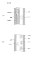
- FIG. (1) for demonstrating the detection method of a target range.
- FIG. (2) for demonstrating the detection method of a target range.
- FIG. (3) for demonstrating the detection method of a target range.
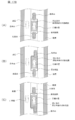
- FIG. 1 is a diagram illustrating a configuration of a travel control device 100 according to the present embodiment.
- the travel control device 100 includes a sensor 110, a vehicle position detection device 120, a map database 130, an in-vehicle device 140, a notification device 150, an input device 160,
- the communication device 170 includes a drive control device 180 and a control device 190. These devices are connected by a CAN (Controller Area Network) or other in-vehicle LAN in order to exchange information with each other.
- CAN Controller Area Network
- Sensor 110 detects the traveling state of the host vehicle.
- a front camera that images the front of the host vehicle
- a rear camera that images the rear of the host vehicle
- a front radar that detects an obstacle ahead of the host vehicle
- a rear that detects an obstacle behind the host vehicle.
- Examples include a radar, a side radar that detects an obstacle present on the side of the host vehicle, a vehicle speed sensor that detects the vehicle speed of the host vehicle, and an in-vehicle camera that images the driver.
- the sensor 110 may be configured to use one of the plurality of sensors described above, or may be configured to use two or more types of sensors in combination.
- the detection result of the sensor 110 is output to the control device 190.
- the own vehicle position detection device 120 includes a GPS unit, a gyro sensor, a vehicle speed sensor, and the like, detects radio waves transmitted from a plurality of satellite communications by the GPS unit, and obtains position information of the target vehicle (own vehicle). The current position of the target vehicle is detected based on the acquired position information of the target vehicle, the angle change information acquired from the gyro sensor, and the vehicle speed acquired from the vehicle speed sensor. The position information of the target vehicle detected by the own vehicle position detection device 120 is output to the control device 190.
- the map database 130 stores map information including position information of various facilities and specific points. Specifically, location information such as a junction, a branch point, a toll gate, a reduced number of lanes, a service area (SA) / a parking area (PA), and the like are stored together with map information.
- location information such as a junction, a branch point, a toll gate, a reduced number of lanes, a service area (SA) / a parking area (PA), and the like are stored together with map information.
- SA service area
- PA parking area
- the map information stored in the map database can be referred to by the control device 190.
- the in-vehicle device 140 is various devices mounted on the vehicle and operates when operated by a driver. Examples of such in-vehicle devices include a steering, an accelerator pedal, a brake pedal, a navigation device, an audio device, an air conditioner, a hands-free switch, a power window, a wiper, a light, a direction indicator, and a horn. When the in-vehicle device 140 is operated by a driver, the information is output to the control device 190.
- the notification device 150 is a device such as a display provided in a navigation device, a display incorporated in a room mirror, a display incorporated in a meter unit, a head-up display projected on a windshield, or a speaker provided in an audio device. .
- the notification device 150 notifies the driver of notification information described later under the control of the control device 190.
- the input device 160 is, for example, a device such as a dial switch that can be manually input by the driver, a touch panel disposed on the display screen, or a microphone that can be input by the driver's voice.
- the driver can input response information for the notification information notified by the notification device 150 by operating the input device 160.
- a direction indicator or other on-vehicle device switch can be used as the input device 160, and the driver gives a direction indication to the controller 190 whether or not to automatically change lanes. It is also possible to enter a lane change permission by turning on the switch. Note that the response information input by the input device 160 is output to the control device 190.
- the communication device 170 communicates with a communication device outside the vehicle.
- the communication device 170 performs vehicle-to-vehicle communication with other vehicles, performs road-to-vehicle communication with devices installed on the road shoulder, or wirelessly communicates with an information server installed outside the vehicle.
- various information can be acquired from the external device.
- Information acquired by the communication device is output to the control device 190.
- the drive control device 180 controls the traveling of the host vehicle. For example, when the own vehicle follows the preceding vehicle (hereinafter also referred to as follow-up running control), the drive control device 180 adjusts the acceleration / deceleration and the vehicle speed so that the distance between the own vehicle and the preceding vehicle becomes a constant distance. Operation of the drive mechanism to realize (in the case of an engine vehicle, the operation of an internal combustion engine, in the case of an electric vehicle system, the operation of an electric motor, and in the case of a hybrid vehicle, the torque distribution between the internal combustion engine and the electric motor is also included. ) And brake operation.
- the operation of the steering actuator is controlled to control the operation of the wheels.
- the drive control device 180 controls the traveling of the host vehicle according to an instruction from the control device 190 described later. Further, as a traveling control method by the drive control device 180, other well-known methods can be used.
- the control device 190 is a ROM (Read Only Memory) that stores a program for controlling the traveling of the host vehicle, a CPU (Central Processing Unit) that executes the program stored in the ROM, and an accessible storage device. It consists of a functioning RAM (Random Access Memory).
- ROM Read Only Memory
- CPU Central Processing Unit
- RAM Random Access Memory
- As an operation circuit instead of or together with a CPU (Central Processing Unit), an MPU (Micro Processing Unit), a DSP (Digital Signal Processor), an ASIC (Application Specific Integrated Circuit), an FPGA (Field Programmable Gate Array), or the like. Can be used.
- the control device 190 executes a program stored in the ROM by the CPU, thereby obtaining a travel information acquisition function for acquiring information related to the travel state of the host vehicle, a travel scene determination function for determining the travel scene of the host vehicle, A travel control function for controlling the travel of the vehicle and a lane change control function for determining whether a lane change is possible and controlling the lane change are realized.
- a travel information acquisition function for acquiring information related to the travel state of the host vehicle
- a travel scene determination function for determining the travel scene of the host vehicle
- a travel control function for controlling the travel of the vehicle
- a lane change control function for determining whether a lane change is possible and controlling the lane change are realized.
- the traveling information acquisition function of the control device 190 acquires traveling information related to the traveling state of the host vehicle.
- the travel information acquisition function can acquire image information outside the vehicle captured by the front camera and the rear camera, and detection results by the front radar, the rear radar, and the side radar as the travel information.
- the travel information acquisition function can also acquire vehicle speed information of the host vehicle detected by the vehicle speed sensor and image information of the driver's face captured by the in-vehicle camera as the travel information.
- the travel information acquisition function can acquire information on the current position of the host vehicle as travel information from the host vehicle position detection device 120, and also includes a junction, a branch point, a toll booth, a decreased number of lanes, a service Position information such as area (SA) / parking area (PA) can be acquired from the map database 130 as travel information.
- SA area
- PA parking area
- the travel information acquisition function can also acquire operation information of the in-vehicle device 140 by the driver from the in-vehicle device 140 as travel information.
- the traveling scene determination function of the control device 190 refers to the table stored in the ROM of the control device 190 to determine the traveling scene in which the host vehicle is traveling.
- FIG. 2 is a diagram illustrating an example of a table used for determination of a traveling scene. As shown in FIG. 2, the table stores a travel scene suitable for lane change and its determination condition for each travel scene.
- the traveling scene determination function refers to the table shown in FIG. 2 and determines whether or not the traveling scene of the host vehicle is a traveling scene suitable for lane change.
- the determination conditions of “catch-up scene to the preceding vehicle” include “detect the preceding vehicle ahead”, “vehicle speed of preceding vehicle ⁇ vehicle speed of own vehicle”, and “arrival to the preceding vehicle”
- Four conditions of “within a predetermined time” and “the direction of lane change is not a lane change prohibition condition” are set.
- the traveling scene determination function also determines whether the host vehicle satisfies the above conditions based on, for example, the detection result of the front camera or the front radar, the vehicle speed of the host vehicle detected by the vehicle speed sensor, and the position information of the host vehicle. If the above condition is satisfied, it is determined that the host vehicle is a “catch-up scene to the preceding vehicle”. Similarly, the traveling scene determination function determines whether or not the determination condition is satisfied for all the traveling scenes registered in the scene determination table.
- the lane change prohibition conditions include, for example, “traveling in a lane change prohibited area”, “there is an obstacle in the lane change direction”, “every time crossing the center line (road center line)”, And “entering the road shoulder or straddling the edge of the road”.
- a configuration that permits the condition “entering the road shoulder or straddling the road edge” in the “emergency evacuation scene” It can also be.
- the lane change necessity, the time limit, and the lane change direction will be described later.
- the traveling scene determination function can determine the traveling scene with the higher necessity of lane change as the traveling scene of the own vehicle when the traveling scene of the own vehicle corresponds to a plurality of traveling scenes. For example, in the example illustrated in FIG. 2, it is assumed that the traveling scene of the host vehicle corresponds to a “catch-up scene of a preceding vehicle” and a “lane transfer scene to a destination”. In this case, it is assumed that the lane change necessity X1 in the “catch-up scene of the preceding vehicle” is lower than the lane change necessity X8 in the “lane change scene to the destination” (X1 ⁇ X8). In this case, the travel scene determination function can determine a “lane transfer scene to the destination” having a higher degree of necessity of lane change as the travel scene of the host vehicle.
- the traveling control function of the control device 190 controls traveling of the host vehicle.
- the travel control function detects the lane mark of the lane (hereinafter also referred to as the own lane) on which the host vehicle travels based on the detection result of the sensor 110 so that the host vehicle travels in the own lane.
- Lane keep control is performed to control the traveling position of the host vehicle in the width direction.
- the travel control function can cause the drive control device 180 to control the operation of the steering actuator or the like so that the host vehicle travels at an appropriate travel position.
- the traveling control function can also perform follow-up traveling control that automatically follows the preceding vehicle with a certain distance between the preceding vehicle and the vehicle.
- the travel control function can cause the drive control device 180 to control the operation of the drive mechanism such as the engine and the brake so that the host vehicle and the preceding vehicle travel at a constant inter-vehicle distance.
- the drive control device 180 can control the operation of the drive mechanism such as the engine and the brake so that the host vehicle and the preceding vehicle travel at a constant inter-vehicle distance.
- the lane change control function of the control device 190 determines whether or not to change the lane based on the traveling scene of the host vehicle and information on obstacles around the host vehicle. Further, the lane change control function can cause the drive control device 180 to control the operation of the steering actuator when it is determined to change the lane. The details of the lane change control method by the lane change control function will be described later.
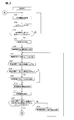
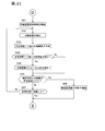
- FIGS. 3 to 5 are flowcharts showing the lane change control process according to the first embodiment.
- the lane change control process described below is executed by the control device 190. In the following description, it is assumed that the following traveling control in which the host vehicle follows the preceding vehicle is performed by the traveling control function of the control device 190.
- step S101 travel information relating to the travel state of the host vehicle is acquired by the travel information acquisition function.
- step S102 the travel scene determination function determines the travel scene of the host vehicle based on the travel information acquired in step S101.
- step S103 the travel scene determination function determines whether the travel scene of the host vehicle determined in step S102 is a travel scene suitable for lane change. Specifically, the travel scene determination function determines that the travel scene of the host vehicle is a travel scene suitable for lane change when the travel scene of the host vehicle is one of the travel scenes shown in FIG. To do. If the traveling scene of the host vehicle is not a traveling scene suitable for lane change, the process returns to step S101, and the determination of the traveling scene is repeated. On the other hand, if the traveling scene of the host vehicle is a traveling scene suitable for lane change, the process proceeds to step S104.
- the target range is detected by the lane change control function.
- the lane change control function is based on image information outside the vehicle imaged by the front camera and the rear camera, and traveling information including detection results by the front radar, the rear radar, and the side radar. Detect obstacles in the vicinity.
- a lane change control function detects the range which is located in the side of the own vehicle, and an obstruction does not exist as a target range.
- the target range is a relative range based on the travel position when the host vehicle travels at the current speed, and when other vehicles existing around the host vehicle go straight at the same speed as the host vehicle. In this case, the target range does not change.
- the “side of the host vehicle” refers to the target position of the lane change when the host vehicle changes lanes (the target position is also relative to the driving position when the host vehicle travels at the current speed).
- the range (direction, width, angle, etc.) can be set as appropriate.
- a method for detecting a target range will be described with reference to FIGS. 6A to 6C.
- 6A to 6C are diagrams for explaining the target range.
- the lane change control function can detect this adjacent lane as the target range.
- the road shoulder is excluded from the target range because it is a range where the lane cannot be changed.
- the shoulder can be included in the target range (the same applies hereinafter).
- the lane change control function can detect this range as the target range.
- the scene example shown in FIG. 6A (C) there is a range where there is no other vehicle in the adjacent lane as in the scene shown in FIG. 6A (B), and the lane next to the adjacent lane (hereinafter referred to as the adjacent lane).
- the adjacent lane Also in the lane), there is a range in which no other vehicle exists between the other vehicles in the front and rear.
- the lane change control function can detect, as target ranges, a range in which no other vehicle exists in the adjacent lane and a range in which no other vehicle exists in the adjacent adjacent lane.
- the lane change control function detects a target range by excluding a range where the host vehicle cannot travel, such as a construction section, from the target range.
- the range in which the host vehicle cannot travel includes, in addition to the construction section, a range in which other vehicles are parked or stopped, a range in which the vehicle is prohibited from traveling due to traffic regulations, and the like.
- the range in which the vehicle cannot travel due to the construction section or the like is, for example, more than half of the adjacent lane (half or more in the width direction), the range less than the remaining half is set. It can also be set as the structure which is not detected as an object range. *
- the lane change control function determines that the target range cannot be detected. can do.
- the lane change control function detects, as a target range, a range in which no obstacle exists in an adjacent lane in which the lane can be changed. That is, in this case, the adjacent adjacent lane where the lane change cannot be performed is not detected as the target range.
- working the road which has an oncoming lane is illustrated.
- the lane change control function detects the target range only in the lane on the traveling side of the host vehicle where the host vehicle can travel. That is, in this case, the target range is not detected in the oncoming lane.
- the lane change control function detects the target range in a direction suitable for lane change in the traveling scene of the host vehicle in the left-right direction.
- directions suitable for lane change in each traveling scene are stored in advance in the table shown in FIG.
- the lane change control function refers to the table shown in FIG. 2 and acquires “lane change direction” information in the traveling scene of the host vehicle. For example, when the traveling scene of the host vehicle is a “catch-up scene to the preceding vehicle”, the lane change control function acquires “passing lane side” as the “lane change direction” with reference to FIG. Then, the lane change control function detects the target range in the acquired “direction of lane change”.
- the lane change control function is “passing lane side”, that is, the lane side where traveling of the passing vehicle is recommended (for example, FIG. 6A to FIG. 6)
- the target range is detected.
- the lane change control function can detect the target range in the direction of lane change suitable for the traveling scene of the host vehicle.
- the lane change control function detects the target range on the side of the host vehicle. For example, even when a range where no obstacle exists in the adjacent lane is detected, if the range is more than a predetermined distance away from the current position of the host vehicle and is positioned on the rear side or the front side of the host vehicle, Since it is difficult to change the lane to such a range, it is not detected as the target range.
- the lane change target position is set by the lane change control function.
- the lane change control function is a position within the target range of the adjacent lane detected in step S104, and a position shifted slightly backward from the position of the host vehicle is set as a target position for lane change.
- the target position for lane change is a relative position with respect to the position where the host vehicle travels. That is, when the position when the host vehicle travels at the current speed is used as the reference position, a position slightly behind the reference position can be set as the target position for lane change.
- FIG. 7 is a figure for demonstrating the setting method of the target position of a lane change.
- the lane change control function is a lane, such as that there is a range where the host vehicle can move within the target range of the adjacent lane, and that there is no other vehicle that may enter the target range around the host vehicle.
- the target position for lane change can be set in consideration of the ease of change.
- the lane change control function can be used when the other vehicle around the target range is making a blinker in the direction of the target range or when the vehicle is traveling closer to the target range. It is determined that there is a possibility of entering the vehicle, and another position within the target range that is less likely to enter another vehicle can be set as the target position.
- step S105 a target route for changing lanes may be set instead of the target position for changing lanes.
- the lane change required time T1 is predicted by the lane change control function.
- the lane change control function can predict the time required for movement from the current position of the host vehicle to the target position for lane change as the required time T1 based on the vehicle speed and acceleration of the host vehicle.
- step S107 the target range after the predetermined time T1 predicted in step S106 is predicted by the lane change control function.
- the lane change control function predicts the travel position of the other vehicle after a predetermined time T1 based on the speed and acceleration of the other vehicle existing around the host vehicle. For example, the lane change control function repeatedly detects the position information of the other vehicle, thereby measuring the speed vector v0, the acceleration vector a0, and the position vector p0 of the other vehicle as shown in FIG.
- the speed vector v0 of the other vehicle is expressed by the following equation (1).
- v0 vx0i + vy0j (1)
- vx0 is a speed component in the X-axis direction of the speed vector of the other vehicle
- vy0 is a speed component in the Y-axis direction of the speed vector of the other vehicle.
- i is a unit vector in the X-axis direction
- j is a unit vector in the Y-axis direction (the same applies to the following formulas (2), (3), and (6)).
- the acceleration vector a0 of the other vehicle can be obtained as shown in the following equation (2)
- the position vector p0 of the other vehicle can be obtained as shown in the following equation (3).
- a0 ax0i + ay0j
- p0 px0i + py0j (3)
- ax0 is the acceleration component in the X-axis direction of the acceleration vector of the other vehicle
- ay0 is the acceleration component in the Y-axis direction of the acceleration vector of the other vehicle.
- px0 is a position component in the X-axis direction of the position vector of the other vehicle
- py0 is a position component in the Y-axis direction of the position vector of the other vehicle.
- the lane change control function calculates a position vector pT1 of another vehicle after a predetermined time T1. Specifically, the lane change control function calculates a position vector pT1 of another vehicle after a predetermined time T1 based on the following equations (4) to (6).
- pxT1 px0 + vx0T1 + 1/2 (ax0T1) 2
- pyT1 py0 + vy0T1 + 1/2 (ay0T1) 2
- pT1 pxT1i + pyT1j (6)
- vx0T1 is the moving speed of the other vehicle in the X-axis direction after a predetermined time T1
- vy0T1 is the moving speed of the other vehicle in the Y-axis direction after the predetermined time T1.
- ax0T1 is the acceleration in the X-axis direction of the other vehicle after the predetermined time T1
- ay0T1 is the acceleration in the Y-axis direction of the other vehicle after the predetermined time T1.
- the lane change control function predicts positions after a predetermined time T1 for all other vehicles existing around the host vehicle.
- the lane change control function predicts the target range after the predetermined time T1 based on the position of the other vehicle after the predetermined time T1.
- the lane change control function is determined in advance by taking into account the lane regulation status after a predetermined time T1, the presence of obstacles on the road, the presence or absence of blockage of adjacent lanes, and the presence of sections where the vehicle cannot move such as construction sections.
- the target range after time T1 can be predicted. Note that the lane change control function can predict the target range after the predetermined time T1 as in step S104.
- step S108 the target range in the adjacent lane after a predetermined time T1 based on the current target range detected in step S104 and the target range after the predetermined time T1 predicted in step S107 by the lane change control function.
- a prediction is made as to whether or not.
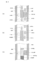
- FIG. 9 is a figure for demonstrating the prediction method of whether an object range will become small.
- the lane change control function compares the current target range (A) with the target range (B) after the predetermined time T1, and determines whether the target range in the adjacent lane becomes smaller after the predetermined time T1. to decide. Specifically, the lane change control function superimposes the current target range (A) and the target range (B) after the predetermined time T1, and the size of the target range of the current adjacent lane is equal to the predetermined time T1.
- the process proceeds to step S109, and notification information that the target range decreases after the predetermined time T1 is notified.
- the lane change control function can notify a warning that the target range becomes smaller after a predetermined time T1 using a display or a speaker included in the notification device 150.
- step S108 the lane change control function compares the current target range (A) with the target range (B) after the predetermined time T1, and after the predetermined time T1, as shown in FIG. 9C.
- a range that disappears from the range that is, a range that is included in the current target range (A) but is not included in the target range (B) after the predetermined time T1 is specified as the disappearance range.
- the lane change control function compares the current target range (A) with the target range (B) after the predetermined time T1, and is added to the target range after the predetermined time T1, as shown in FIG. 9C.
- a range that is not included in the current target range (A) but is included in the target range (B) after the predetermined time T1 is specified as an additional range.
- the lane change control function can be configured to notify the driver of notification information including information on the disappearance range or the additional range in step S109 when the disappearance range or the additional range is specified.
- the lane change control function can display the disappearance range and the additional range in different display modes on the display of the notification device 150 as shown in FIG. As a result, the driver can appropriately grasp the disappearance range and the additional range.
- FIG. 10 is a diagram illustrating an example of notification information displayed on the display of the notification device 150.
- the lane change control function can be configured to notify the notification information that the target range is reduced only when the size of the target range becomes smaller than the predetermined range after the predetermined time T1. Further, the lane change control function can be configured to notify the disappearance range and the additional range when the disappearance range and the additional range are larger than a predetermined size. Further, the lane change control function can also change the display mode of the disappearance range or the target range after the predetermined time T1 according to the size of the disappearance range. For example, the lane change control function determines whether the erasure range or the target range after a predetermined time T1 when the size of the disappearance range is greater than or equal to a predetermined range and when the size of the disappearance range is less than the predetermined range.
- the display mode can be changed. For example, when the size of the disappearance range is less than a predetermined range, the lane change control function displays the disappearance range or the target range after the predetermined time T1 in green or the like, and the size of the disappearance range is the predetermined range. In the case described above, the disappearance range or the target range after the predetermined time T1 can be highlighted and displayed in red or the like. Further, the lane change control function may be configured to blink the disappearance range or the target range after the predetermined time T1 when the size of the disappearance range is equal to or larger than the predetermined range. In addition, when the size of the disappearance range is greater than or equal to a predetermined range, a predetermined warning lamp provided on the indicator may be turned on.
- the notification device 150 when the size of the disappearance range is equal to or greater than the predetermined range, the driver's attention is drawn compared to the case where the size of the disappearance range is less than the predetermined range. It is good also as a structure which outputs the sound of a timbre or a volume.
- the lane change control function can also change the display mode of the disappearance range according to the speed at which the target range becomes smaller. For example, the lane change control function may be configured to highlight the disappearance range or the target range after a predetermined time T1 with red or blinking display when the speed at which the target range becomes smaller than a predetermined speed. .
- the required range information is acquired by the lane change control function.
- the required range is a range of a size that is necessary when the host vehicle changes lanes, and is a range that has at least a size that the host vehicle occupies on the road surface.
- the required range when the required range is set at the target position for lane change, and the target range of the adjacent lane includes the required range, the space corresponding to the required range in the target range of the adjacent lane Lane change is permitted.
- information including the shape and size of the required range is stored in the memory of the control device 190, and the lane change control function can acquire the required range information from the memory of the control device 190.
- step S111 the required range acquired in step S110 is corrected by the lane change control function.
- the lane change control function can correct the required range by combining any one of the conditions described below or a combination of two or more conditions.
- the lane change control function can correct the required range according to the necessity of lane change in the traveling scene of the host vehicle.
- the degree of necessity of lane change in each travel scene is stored in advance in the table shown in FIG.
- the lane change control function refers to the table shown in FIG. 2 and acquires the degree of necessity of lane change in the traveling scene of the host vehicle. For example, in the “catch-up scene to the preceding vehicle”, the lane change control function can obtain “X1” as the degree of necessity of lane change with reference to the table shown in FIG.
- the required range can be reduced in the traveling direction of the host vehicle by shortening the length of the required range in the traveling direction of the host vehicle.
- the lane change control function in the example shown in FIG. 11, when (A) is the required range before correction, the lane change necessity X1 is high (the lane change necessity is equal to or greater than a predetermined value st1). In some cases, as shown in (B), the required range can be reduced in the traveling direction of the host vehicle.
- the lane change control function corrects the required range in a range where the required range is not smaller than the range in which the host vehicle occupies the road surface. Further, the lane change control function can be configured to reduce the required range as the degree of necessity of lane change in the traveling scene of the host vehicle is larger. Further, although not shown, the lane change control function is a required range before correction when the lane change necessity X1 is low (the lane change necessity is less than a predetermined value st2 (st1> st2)). Compared to the above, the required range can be increased in the traveling direction of the host vehicle.
- the lane change control function detects a target range where no other vehicle exists in a lane that is further adjacent to the adjacent lane (adjacent adjacent lane), and corrects the required range based on the detected target range of the adjacent lane. can do.
- the lane change control function detects a space (for example, a space corresponding to the required range) in which another vehicle (hereinafter also referred to as an adjacent vehicle) traveling in the adjacent lane can change the lane within the target range of the adjacent adjacent lane.
- an adjacent vehicle traveling in the adjacent lane can change the lane within the target range of the adjacent adjacent lane.
- the lane change control function reduces the required range by reducing the length of the required range in the traveling direction of the host vehicle when the adjacent vehicle can detect a space in the adjacent adjacent lane where the lane can be changed. Reduce in the direction of travel of the vehicle.
- the lane change control function when (A) is the required range before correction, the lane change control function, as shown in (B), creates a space in the adjacent adjacent lane where the adjacent vehicle can change lanes. If it can be detected, the required range can be reduced in the traveling direction of the host vehicle by shortening the length of the required range in the traveling direction of the host vehicle.
- the lane change control function can be configured to reduce the required range in the traveling direction of the host vehicle as the space in which the adjacent vehicle can change lanes in the adjacent adjacent lane increases.
- the lane change control function can correct the required range based on the travel position in the width direction of another vehicle (adjacent vehicle) traveling in the adjacent lane. Specifically, the lane change control function detects the travel position in the width direction of the adjacent vehicle, and requests when the travel position in the width direction of the adjacent vehicle is closer to the own lane side than the center of the adjacent lane.
- the required range is increased by increasing the range in the traveling direction of the host vehicle. More specifically, when the adjacent vehicle travels ahead of the own vehicle, the lane change control function increases the length of the required range in the forward direction of the own vehicle, and the adjacent vehicle is behind the own vehicle. When traveling, the length of the required range is increased in the rear direction of the host vehicle. For example, in the example shown in FIG.
- the lane change control function indicates that the adjacent vehicle is ahead of the host vehicle from the center of the adjacent lane, as shown in (B). However, when driving closer to the own lane, the required range is increased forward, and as shown in (C), the adjacent vehicle is closer to the own lane than the center of the adjacent lane, behind the own vehicle. When traveling, the required range can be increased backward.
- the lane change control function increases the required range of the vehicle as the adjacent vehicle is closer to the own lane (the shorter the distance in the width direction from the lane mark on the adjacent lane to the adjacent vehicle is). It can also be configured to increase in the direction.
- the lane change control function when the traveling position in the width direction of the adjacent vehicle is closer to the opposite side of the own lane than the center of the adjacent lane, by shortening the required range in the traveling direction of the own vehicle, Reduce the required range. More specifically, the lane change control function reduces the required range from the front when the adjacent vehicle travels ahead of the host vehicle, and when the adjacent vehicle travels behind the host vehicle, Reduce the required range from the rear. For example, in the example shown in FIG. 13B, when (A) is the required range before correction, as shown in (B), the lane change control function indicates that the adjacent vehicle is ahead of the host vehicle and the adjacent lane.
- the required range When traveling closer to the opposite side of the own lane than the center, the required range is made smaller from the front, and as shown in (C), the adjacent vehicle is behind the own vehicle and behind the center of the adjacent lane. When traveling near the opposite side of the own lane, the required range can be reduced from the rear.
- the lane change control function allows the required range to be set as the adjacent vehicle approaches the opposite side of the own lane (the longer the distance in the width direction from the lane mark on the own vehicle side of the adjacent lane to the adjacent vehicle). It can also be set as the structure made small in the advancing direction.
- the lane change control function can correct the required range based on the lighting state of the blinker of another vehicle (adjacent vehicle) traveling in the adjacent lane. Specifically, the lane change control function detects the lighting state of the blinker of the adjacent vehicle, and when the blinker on the own lane side is lit, by extending the required range in the traveling direction of the own vehicle, Increase the required range. More specifically, the lane change control function increases the length of the required range in the forward direction of the host vehicle when an adjacent vehicle traveling ahead of the host vehicle lights the blinker on the host lane side. When the adjacent vehicle that travels behind the host vehicle is lit with the blinker on the host lane side, the length of the required range is increased in the rear direction of the host vehicle.
- the lane change control function when (A) is the required range before correction, the lane change control function, as shown in (B), indicates that the adjacent vehicle is ahead of the own vehicle and the winker on the own lane side. When traveling while lighting up, the required range can be increased forward. Further, as shown in (C), the lane change control function can increase the required range rearward when an adjacent vehicle travels behind the host vehicle while lighting the winker on the own lane side. .
- the lane change control function reduces the required range by shortening the required range in the traveling direction of the own vehicle when the adjacent vehicle lights the blinker on the side opposite to the own lane. More specifically, the lane change control function reduces the required range from the front when an adjacent vehicle traveling ahead of the host vehicle lights a blinker on the opposite side of the host vehicle, However, if the adjacent vehicle traveling behind lights up the blinker on the side opposite to the own lane, the required range is reduced from the rear. For example, in the example shown in FIG. 14B, when (A) is the required range before correction, the lane change control function indicates that the adjacent vehicle is ahead of the own vehicle and opposite to the own lane, as shown in (B).
- the required range can be reduced from the front.
- the lane change control function reduces the required range from the rear when an adjacent vehicle travels behind the own vehicle while turning on the blinker on the side opposite to the own lane. Can do.
- the lane change control function can correct the required range based on the speed and acceleration of another vehicle (adjacent vehicle) traveling in the adjacent lane. Specifically, the lane change control function detects the speed and acceleration of the adjacent vehicle, and predicts whether the adjacent vehicle moves away from the own vehicle from the speed and acceleration of the adjacent vehicle, for example, as shown in FIG. . The lane change control function reduces the required range in the traveling direction of the subject vehicle by shortening the requested range in the traveling direction of the subject vehicle when the adjacent vehicle is predicted to move away from the own vehicle.
- the lane change control function is such that when an adjacent vehicle traveling ahead of the own vehicle moves away from the own vehicle, the required range is reduced from the front, and the adjacent vehicle traveling behind the own vehicle When moving away from the host vehicle, the required range is reduced from the rear.
- the lane change control function increases the required range in the traveling direction of the host vehicle by increasing the required range in the traveling direction of the host vehicle when the adjacent vehicle is predicted to approach the host vehicle. More specifically, the lane change control function is configured such that when an adjacent vehicle traveling ahead of the host vehicle approaches the host vehicle, the required range is increased forward, and the adjacent vehicle traveling rearward of the host vehicle is When approaching the host vehicle, the required range can be increased backward.
- the lane change control function may be configured to correct the target range of the adjacent lane instead of the configuration to correct the required range.
- the lane change control function replaces the configuration in which the required range is corrected according to the necessity of lane change in the travel scene of the own vehicle, as shown in FIG. 15. It can be set as the structure which correct
- the lane change control function when the lane change necessity is high (when the lane change necessity is a predetermined value or more), the lane change necessity is low (the lane change necessity degree).
- the target range in the adjacent lane can be increased in the traveling direction of the host vehicle by increasing the target range in the adjacent lane in the traveling direction of the host vehicle. For example, in the example shown in FIG.
- the lane change necessity is high (the lane change necessity is equal to or greater than a predetermined value).
- the target range of the adjacent lane can be increased in the traveling direction of the host vehicle.
- the lane change control function may be configured to increase the target range of the adjacent lane in the traveling direction of the host vehicle as the necessity of lane change in the traveling scene of the host vehicle is higher.
- the lane change control function is based on the target range in the adjacent adjacent lane as shown in FIG. 16, instead of the configuration in which the required range is corrected based on the target range in the adjacent adjacent lane. It can be set as the structure which correct
- the lane change control function indicates that the adjacent vehicle is within the target range of the adjacent adjacent lane as shown in (B). If a lane changeable space (for example, a space corresponding to the required range) can be detected, the target range of the adjacent lane is made longer by moving the target range of the adjacent lane in the traveling direction of the host vehicle. Can be larger in the direction.
- the lane change control function may be configured to increase the target range of the adjacent lane in the traveling direction of the host vehicle as the target range in the adjacent adjacent lane is larger.
- the lane change control function is replaced with a configuration in which the required range is corrected based on the travel position in the width direction of another vehicle (adjacent vehicle) traveling in the adjacent lane.
- it can be set as the structure which correct
- the lane change control function detects the travel position in the width direction of the adjacent vehicle, and if the travel position in the width direction of the adjacent vehicle is closer to the own lane side than the center of the adjacent lane, Decrease the target range of the lane in the traveling direction of the host vehicle.
- the lane change control function reduces the target range of the adjacent lane from the front direction of the own vehicle, and the adjacent vehicle is behind the own vehicle.
- the target range of the adjacent lane is reduced from the rear direction of the host vehicle.
- the lane change control function indicates that the adjacent vehicle is ahead of the own vehicle as shown in (B).
- the target range of the adjacent lane can be reduced from the front.
- the lane change control function can reduce the target range of the adjacent lane from behind when the adjacent vehicle travels behind the own vehicle toward the own lane. .
- the lane change control function automatically adjusts the target range of the adjacent lane as the adjacent vehicle is closer to the own lane (the shorter the distance in the width direction from the lane mark on the adjacent lane to the adjacent vehicle is). It can also be set as the structure made small in the advancing direction of a vehicle.
- the lane change control function is configured to increase the target range in the traveling direction of the own vehicle when the traveling position in the width direction of the adjacent vehicle is closer to the opposite side of the own lane than the center of the adjacent lane. be able to. More specifically, when the adjacent vehicle travels ahead of the host vehicle, the lane change control function increases the target range in the forward direction of the host vehicle, and the adjacent vehicle travels behind the host vehicle. In this case, the target range is increased in the rear direction of the host vehicle. For example, in the example shown in FIG. 17B, when (A) is the target range of the adjacent lane before correction, the lane change control function indicates that the adjacent vehicle is ahead of the own vehicle as shown in (B).
- the target range of the adjacent lane When traveling near the opposite side of the vehicle, the target range of the adjacent lane is enlarged forward, and as shown in (C), the adjacent vehicle travels behind the own vehicle closer to the opposite side of the own lane. In this case, the target range of the adjacent lane can be increased backward.
- the lane change control function allows the target range of the adjacent lane to increase as the adjacent vehicle moves closer to the opposite side of the own lane (the longer the distance in the width direction from the lane mark on the own vehicle side of the adjacent lane to the adjacent vehicle). It can also be set as the structure which enlarges to the advancing direction of the own vehicle.
- the lane change control function is replaced with a configuration that corrects the required range based on the lighting state of the blinker of the adjacent vehicle, as shown in FIG. 18A and FIG. 18B. It can be set as the structure which correct
- the lane change control function when the adjacent vehicle lights the blinker on the own lane, shortens the target range of the adjacent lane in the traveling direction of the own vehicle, thereby Is reduced in the traveling direction of the host vehicle.
- the lane change control function is configured to reduce the target range of the adjacent lane from the front when the adjacent vehicle traveling ahead of the own vehicle lights up the blinker on the own lane. If the adjacent vehicle running behind the vehicle lights the blinker on the own lane side, the target range of the adjacent lane is reduced from the rear.
- the lane change control function indicates that the adjacent vehicle is ahead of the own vehicle as shown in (B).
- the target range of the adjacent lane can be reduced from the front.
- the lane change control function reduces the target range of the adjacent lane from the rear when the adjacent vehicle travels behind the own vehicle while turning on the blinker on the own lane side. be able to.
- the lane change control function can increase the target range of the adjacent lane in the traveling direction of the own vehicle when the adjacent vehicle lights up the blinker on the opposite side of the own lane. More specifically, the lane change control function increases the target range of the adjacent lane forward when the adjacent vehicle traveling ahead of the own vehicle lights up the blinker on the opposite side of the own lane, When the adjacent vehicle that travels behind the host vehicle lights the blinker on the side opposite to the host vehicle lane, the target range is increased rearward. For example, in the example shown in FIG. 18B, when (A) is the target range of the adjacent lane before correction, the lane change control function indicates that the adjacent vehicle is ahead of the own vehicle as shown in (B).
- the target range of the adjacent lane can be enlarged forward.
- the lane change control function sets the target range of the adjacent lane to the rear. Can be bigger.
- the lane change control function may be configured to correct the target range of the adjacent lane based on the speed and acceleration of the adjacent vehicle, instead of the configuration of correcting the required range based on the speed and acceleration of the adjacent vehicle. .
- the lane change control function predicts whether or not the adjacent vehicle moves away from the own vehicle from the speed and acceleration of the adjacent vehicle, and if the adjacent vehicle is predicted to move away from the own vehicle, the adjacent lane changes.
- the target range of the adjacent lane is increased by making the target range of the vehicle longer in the traveling direction of the host vehicle. More specifically, the lane change control function increases the target range of the adjacent lane forward and travels behind the own vehicle when an adjacent vehicle traveling ahead of the own vehicle moves away from the own vehicle. When the adjacent vehicle moves away from the host vehicle, the target range of the adjacent lane is increased backward.
- the lane change control function reduces the target range of the adjacent lane in the traveling direction of the host vehicle by shortening the target range of the adjacent lane in the traveling direction of the host vehicle when the adjacent vehicle approaches the own lane. be able to. More specifically, the lane change control function reduces the target range of the adjacent lane from the front and travels behind the host vehicle when an adjacent vehicle traveling ahead of the host vehicle approaches the host vehicle. When the adjacent vehicle approaches the host vehicle, the target range of the adjacent lane can be reduced from the rear.
- step S111 it is assumed that the required range is corrected in step S111.
- step S112 the lane change control function determines whether there is a space corresponding to the required range corrected in step S111 within the target range of the adjacent lane after the predetermined time T1 predicted in step S107. Specifically, as shown in FIG. 19A, the lane change control function sets the corrected requested range to the target position for lane change set in step S105. Then, the lane change control function determines whether or not the corrected requested range is included in the target range of the adjacent lane after the predetermined time T1. For example, in the example shown in FIG. 19A, the corrected target range is not included in the target range of the adjacent lane after the predetermined time T1, and therefore the lane change control function is the target range of the adjacent lane after the predetermined time T1.
- the lane change control function when the corrected required range is included in the target range of the adjacent lane after the predetermined time T1, a space corresponding to the corrected required range within the target range of the adjacent lane after the predetermined time T1. Judge that there is. If there is a space corresponding to the corrected requested range within the target range of the adjacent lane after the predetermined time T1, the process proceeds to step S114 shown in FIG. 4, and if there is no space, the process proceeds to step S113.
- step S113 it is determined that the corrected requested range is not included in the target range of the adjacent lane after the predetermined time T1, and the space corresponding to the required range cannot be detected in the target range of the adjacent lane after the predetermined time T1. ing. Therefore, in step S113, the target position for lane change is changed by the lane change control function. Specifically, the lane change control function resets the target position for lane change so that the target range of the adjacent lane after the predetermined time T1 includes the corrected required range. For example, as shown in FIG. 19A, when the front portion of the required range is not included in the target range of the adjacent lane after the predetermined time T1, the target position for lane change is changed backward. Accordingly, as shown in FIG.
- the corrected requested range is included in the target range of the adjacent lane after the predetermined time T1, and corresponds to the required range in the target range of the adjacent lane after the predetermined time T1. It is determined that the space to be detected can be detected. After step S113, the process returns to step S106, and the target range is detected again.
- step S114 a lane change control inquiry process is performed by the lane change control function.
- the lane change control is control for executing the lane change.
- step S114 an inquiry about whether or not the lane change control can be executed is made to the driver before the lane change is actually executed.
- step S115 it is determined whether or not the driver has permitted lane change in response to the inquiry in step S114.
- the process proceeds to step S116.
- the driver does not permit the lane change, the process returns to step S101.
- step S104 the lane change control function notifies the inquiry information including the options of “follow” and “change over the lane” along with the message “What do you do with the preceding vehicle?” It can be displayed on the display of the device 150.
- the driver can select one of the options via the input device 160. For example, if the driver selects “change lane and overtake”, the lane change control function determines that the driver has permitted lane change in step S115, and proceeds to step S116. On the other hand, when the driver selects “follow”, the lane change control function determines in step S115 that the driver does not permit the lane change, and returns to step S101.
- the lane change control function presents the choices of “follow” and “change over lane” as inquiry information along with the message “What do you do with the preceding vehicle?” “If the selection button is not pressed within seconds, it will be selected automatically.” In this case, if the driver does not select one of the options within a certain period, the lane change control function automatically selects a predetermined default option between “Follow” and “Change lane and overtake”. can do.
- the default option may be a unique option or an option that can be variably set. For example, the lane change control function sets “follow” as the default option when the target range is small for a certain period of time until the default option is selected.
- the configuration may be such that “change lane and overtake” is set as a default option.
- the lane change control function may be configured to set, as a default option, an option that is frequently selected by the driver based on a past history in which the driver has selected an option. In this case as well, if the driver selects “change lane and overtake” within a certain time, the process proceeds to step S116, and if “follow” is selected within a certain time, the process returns to step S101. .
- the lane change control function cancels the lane change with a message such as "Changing the lane of the preceding vehicle and overtaking” or "Press the cancel button below if you want to cancel the lane change".
- Inquiry information including a “cancel” button can be notified to the driver via the notification device 150.
- step S114 it is treated in step S115 that the driver has permitted the lane change, and the process proceeds to step S117.
- step S117 lane change control is started. When the driver presses the “Cancel” button, the lane change control is canceled and the process returns to Step S101.
- step S116 the lane change time limit is acquired by the lane change control function.
- the time until the host vehicle approaches a point where it is difficult to change the lane in each travel scene is stored in the table as a time limit.
- the lane change control function refers to the table shown in FIG. 2 and acquires the time limit (Z) in the traveling scene of the host vehicle.
- the time limit is stored as arrival time to the preceding vehicle— ⁇ seconds.
- the travel control function refers to the table shown in FIG.
- ⁇ is a predetermined number of seconds (for example, 5 seconds) and can be set as appropriate for each traveling scene. For example, when the arrival time (TTC) to the preceding vehicle is 30 seconds and ⁇ is 5 seconds, the time limit for changing the lane is 25 seconds.
- step S117 lane change control is started by the lane change control function.
- the lane change control function causes the drive control device 180 to start controlling the operation of the steering actuator so that the host vehicle moves to the lane change target position set in step S105 or step S113.
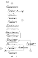
- step S123 the lane change control function determines whether there is a space corresponding to the required range corrected in step S111 within the target range of the adjacent lane after the predetermined time T2 predicted in step S120. Is called.
- the lane change control function sets the required range after correction at the target position for lane change, and the adjacent lane after the predetermined time T2 when the target range of the adjacent lane after the predetermined time T2 includes the corrected required range. It is determined that there is a space corresponding to the required range in the target range, and the process proceeds to step S124. On the other hand, if it is determined that there is no space corresponding to the required range in the target range of the adjacent lane after the predetermined time T2, the process proceeds to step S128.
- step S124 the lane change control function determines whether or not the time limit Z acquired in step S117 has elapsed since the start of lane change control in step S116.
- the process proceeds to step S127, while the elapsed time S1 after the start of the lane change control does not exceed the limit time Z. In the case, the process proceeds to step S125.
- step S125 the lane change control function determines whether the host vehicle has reached the target position for lane change. If the host vehicle has reached the target position for lane change, the lane change control is terminated in step S126, and the lane change control process is terminated. Thereby, the lane change of the own vehicle is completed. On the other hand, if the host vehicle has not reached the target position for lane change, the process returns to step S118 and lane change control is continued.
- step S124 if the elapsed time S1 since the start of the lane change control exceeds the time limit Z, that is, the target position for the lane change even if the time limit Z has elapsed since the start of the lane change control. If not reachable, the process proceeds to step S127.
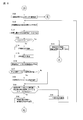
- step S127 the lane change control is canceled by the lane change control function. Specifically, the lane change control function notifies the driver of information indicating that the lane change control is to be stopped. For example, the lane change control function can notify a driver of the message “lane change will be interrupted due to timeout” via the notification device 150. Then, lane change control is complete
- the lane change control function may leave the travel position in the width direction of the host vehicle at the position at the end of the lane change control, or return to the position at the start of the lane change control. It is good also as a structure.
- a message such as “return to original position due to timeout” may be notified to the driver.
- the lane change control function confirms whether or not to continue the lane change while maintaining the current driving state, and if the driver desires to continue the lane change.
- the time limit Z can be extended.
- the lane change control function presents to the driver notification information including a message “Time-out but continue lane change?” And options of “Do not continue” and “Continue” Can do.
- the driver selects the “continue” option
- the lane change control function returns to step S118 after extending the time limit Z, while the driver selects the “do not continue” option.
- step S126 the lane change control is terminated.
- the lane change control function provides a response time when confirming whether or not to continue to change lanes to the driver, and automatically executes default options when there is no response from the driver within the response time. It is good. For example, in addition to the message “Timed out but continue lane change?”, “Do not continue” and “Continue” choices, “If the selection button is not pressed within XX seconds The message “automatically selected” can be included in the inquiry information to inform the driver.
- the answer time and the default option may be a unique time or option, or may be variably set. For example, as an example of variably setting the answer time and the default option, when the target range is small, the answer time is shortened, or “do not continue” is set as the default option. it can.
- the response time can be shortened, and an option with a large number of times the driver has selected can be set as a default option. If the “continue” option is selected, the time limit Z is extended, and then the process returns to step S118. If the “do not continue” option is selected, the lane change control is performed in step S126. Is terminated.
- the lane change control function can automatically continue the lane change and notify the driver of the method of canceling the lane change. For example, the lane change control function cancels the lane change with a message such as "Timed out but continue lane change" or "If you want to cancel lane change, please press the cancel button below.”
- the notification information including the “cancel” button for performing the notification can be notified to the driver via the notification device 150. In this case, if the “cancel” button is not pressed, after the time limit Z is extended, the process returns to step S118. On the other hand, if the “cancel” button is pressed, the lane change control is terminated in step S126.
- the time limit Z is extended within a time period during which the lane change can be continued.
- the traveling scene of the host vehicle is a “scene close to the merging point”, it is 10 seconds to the merging point, and the time limit Z is 7 seconds
- the lane change control function is the time limit Z 7 If it exceeds 2 seconds, the time limit Z can be extended to 9 seconds, for example, and the lane change can be continued. In this case, the lane change control is ended when the extended time limit Z (9 seconds) is exceeded.
- the lane change control is canceled, so that the time limit Z has elapsed since the start of the lane change control.
- the driver's intention to change the lane changes the lane change is done after the driver no longer wants the lane change, or the lane change is done when the driver forgets It is possible to effectively prevent the driver from feeling uncomfortable.
- step S123 if it is determined that there is no space corresponding to the required range in the target range of the adjacent lane after the predetermined time T2, the process proceeds to step S128.
- step S112 when the lane change control is started, there is a space corresponding to the required range in the target range of the adjacent lane, but after the start of the lane change control, it corresponds to the required range in the target range of the adjacent lane. If there is no more space, the process proceeds to step S128.
- step S123 when the target range of the adjacent lane at the time of step S112 at which the lane change control is started becomes small at the time of step S123, the process may proceed to step S128.
- step S128 a positional relationship in the width direction between the lane mark (hereinafter also referred to as a target lane mark) that the host vehicle strides in the lane change and the host vehicle is detected.
- FIG. 20 illustrates a scene where the host vehicle changes lanes in the direction indicated by the arrow in the figure (from the left lane to the right lane in the figure).
- the lane change control function is such that a part of the host vehicle does not straddle the target lane mark, as shown in FIG.
- the center line of the host vehicle does not straddle the lane mark, although the center line of the host vehicle does not straddle the lane mark.
- FIG. 20D a state where the vehicle is straddling the lane mark is determined as to whether the entire vehicle is straddling the lane mark.
- step S129 a control process for stopping or continuing the lane change is performed by the lane change control function based on the positional relationship between the target lane mark determined in step S128 and the own vehicle in the width direction.
- the lane change control function is based on the positional relationship between the target lane mark and the host vehicle in the width direction, (a) a method of presenting information to the driver when lane change is stopped or continued, (c ) Control after stopping or continuing the lane change, (d) determining the travel position of the host vehicle when the lane change is stopped or continued.
- lane change control function (a) as a method of presenting information to the driver when lane change is stopped or continued, (a1) to allow the driver to select an option to stop or continue lane change without time limit If the driver selects one of the options, control the option selected by the driver (stop or continue lane change), (a2) cancel the lane change to the driver with a time limit Or, if the driver chooses one of the options within the time limit and provides information for selecting the option to continue, control the option selected by the driver (stop or continue lane change), If the driver does not select any of the options within the time limit, a predetermined option for canceling and continuing the lane change control Control (default control), (a3) automatically canceling or continuing the lane change, clearly telling the driver how to cancel the lane change canceling or continuing automatically, and (a4) 4) It is possible to perform four methods: automatically canceling or continuing the lane change, and not showing the driver how to cancel the canceled or continued lane change automatically.
- the lane change control function includes (b) canceling lane change or continuing control, and (b1) canceling lane change and automatic driving control. (B2) canceling only lane change control and automatically Travel control continues. (B3) The lane change control is interrupted and placed in a standby state until the space corresponding to the required range is detected again in the target range of the adjacent lane, and the target range of the adjacent lane corresponds to the required range. When the space is detected again, three controls of resuming the lane change control can be executed.
- the lane change control function (c) returns the host vehicle to the position before the lane change start as the travel position of the host vehicle when the lane change control is stopped or continued, (c2) before the lane change start In the lane in which the host vehicle was traveling, three position adjustments of moving the host vehicle to a position near the target lane mark and (c3) maintaining the current position can be executed.
- the lane change control function is based on the positional relationship between the target lane mark and the host vehicle in the width direction, (a) a method of presenting information to the driver when lane change is stopped or continued, and (b) lane change.
- the control content for stopping or continuing the lane change can be performed by appropriately combining the details of the control after the stop or the continuation, and (c) the traveling position of the host vehicle when the lane change is stopped or continued.
- the lane change control function automatically (a4) cancels the lane change when a part of the host vehicle does not straddle the target lane mark, Can be configured not to explicitly indicate a method of canceling the lane change cancellation.
- the lane change control function can be configured such that (b1) the lane change is stopped and the automatic travel control is stopped, and (c1) the host vehicle is returned to the position before the lane change is started. Also, in such a case, the lane change control function will “return to the original position because the lane change space is likely to disappear.” “When the vehicle returns to the original position, the automatic travel control is canceled. As described above, the driver can be notified of the details of the control for canceling the lane change to be performed. In this case, the process proceeds to step S126, and the lane change control is terminated.
- the lane change control function has a part of the host vehicle straddling the target lane mark, but the center line of the host vehicle does not straddle the target lane mark.
- the lane change can be automatically canceled and the driver can be clearly configured to cancel the lane change.
- the lane change control function is (c2) after moving the host vehicle to a position near the target lane mark in the lane in which the host vehicle was traveling before starting the lane change, and (b2) lane change control only. Can be stopped, and automatic traveling control can be continued.
- the lane change control function will “return to the original lane because the lane change space is likely to disappear.”, “Continue with the previous automatic driving control when returning to the original position.
- the driver can be notified of the control details of the lane change cancellation to be performed.
- the lane change control function can display a button for continuing the lane change on the display together with a message “Please press the following button if you want to continue the lane change”. If the driver presses the button for continuing the lane change, the process proceeds to step S130. On the other hand, if the driver does not press the button for continuing the lane change, the process proceeds to step S126.
- the lane change control function is as follows when the entire own vehicle does not straddle the target lane mark but the center line of the own vehicle straddles the target lane mark. a4) The lane change can be continued automatically and the driver can be configured not to explicitly indicate a method for canceling the lane change. Further, in this case, the lane change control function (c3) stands by keeping the traveling position of the host vehicle at the current position, and (b3) the lane until the space corresponding to the required range is detected again in the target range of the adjacent lane. It is possible to adopt a configuration in which the lane change control is resumed when the change is interrupted and a space corresponding to the required range is detected again in the target range of the adjacent lane.
- the lane change control function will "wait at the current location because the lane change space is likely to run out", "If the lane change space seems to be free, lane change control is resumed.” As described above, it is possible to notify the driver of the control details of the lane change continuation to be performed. In this case, the process proceeds to step S130.
- the lane change control function when the entire vehicle straddles the lane mark, (a4) automatically cancels the lane change and Can be configured so as not to clearly indicate a method of canceling the suspension of the lane change control.
- the lane change control function can be configured to continue the automatic travel control by (c3) maintaining the travel position of the host vehicle at the current position, and (b2) stopping only the lane change control. .
- the lane change control function will perform the following lane, such as "I will wait at the current location because the lane change space is likely to run out" and "Continue the previous automatic driving control.” It is possible to notify the driver of the control details of the change cancellation. In this case, the process proceeds to step S126, and the travel control process is terminated.
- the positional relationship between the target lane mark and the host vehicle in the width direction is not limited to the four shown in FIGS. 20A to 20D, and may be five or more, or three or less.
- the combination of the control with respect to each positional relationship is not limited to the combination described above, (a) a method of presenting information to the driver when lane change control is stopped or continued, (b) lane change control is stopped or The control content after the continuation and (c) the traveling position of the host vehicle when the lane change is stopped or continued can be appropriately combined.
- step S130 the elapsed time S2 after the lane change control is set in the standby state in step S129 is measured by the lane change control function. That is, in this embodiment, when the lane change is continued in step S129, the lane change is interrupted until the space corresponding to the required range is detected again in the target range of the adjacent lane, and the lane change control is in the standby state. Become. In step S130, an elapsed time S2 from when the standby for lane change control is started is measured.
- step S131 the required time T3 until the host vehicle moves from the current position to the target position for lane change is predicted by the lane change control function.
- the required time T3 can be predicted in the same manner as in step S106.
- step S132 whether the total time (S2 + T3) of the elapsed time S2 measured in step S130 and the required time T3 predicted in step S131 exceeds the time limit Z acquired in step S118 by the lane change control function. A determination is made whether or not. If the total time (S2 + T3) exceeds the time limit Z, the process proceeds to step S133, where the lane change control function releases the waiting state for the lane change control, and the host vehicle moves to the travel position of the host vehicle before the start of the lane change. Moved. Then, it progresses to step S126 and lane change control is complete
- step S139 as in step S123, it is determined whether there is a space corresponding to the required range corrected in step S111 within the target range of the adjacent lane after the predetermined time T3 predicted in step S136. Is called.
- the lane change control function sets a corrected required range to the target position for lane change, and when the target range of the adjacent lane after the predetermined time T3 includes the corrected required range, the adjacent lane after the predetermined time T3 It is determined that there is a space corresponding to the required range within the target range, and the process proceeds to step S140.
- step S140 since a space corresponding to the required range is detected in the target range of the adjacent lane, the waiting state of the lane change control is canceled by the lane change control function, and the lane change control is resumed. Then, the process returns to step S118. On the other hand, if it is determined that there is no space corresponding to the required range in the target range of the adjacent lane after the predetermined time T3, the process proceeds to step S141, the standby state of the lane change control is continued, and then the process returns to step S130. .
- the travel control device 100 when determining whether or not to allow lane change, has a range that is equal to or larger than the range that the host vehicle occupies on the road surface at the target position for lane change. Is set as the required range. Further, a range where no obstacle exists at the timing when the host vehicle completes the lane change is detected as a target range. Then, when the target range of the adjacent lane includes the required range, it is determined that there is a space in the adjacent lane where the own vehicle can be changed, and the lane change is permitted.
- the present embodiment by comparing the target range in which no obstacle exists in the adjacent lane at the timing when the own vehicle completes the lane change with the required range that the own vehicle needs for the lane change, It is possible to appropriately determine whether or not the vehicle lane can be changed.
- the target range of the adjacent lane is compared with the required range and a space corresponding to the required range is detected in the target range of the adjacent lane, as shown in FIG.
- the lane change necessity in the scene is large (when the lane change necessity is greater than or equal to a predetermined value st1)
- the lane change necessity in the traveling scene of the host vehicle is small (the lane change necessity is predetermined).
- the required range is reduced or the target range of the adjacent lane is increased.
- the traveling scene of the host vehicle is a traveling scene suitable for lane change, the lane change is likely to be permitted. Therefore, whether or not the lane change is possible can be appropriately determined according to the traveling scene of the host vehicle. it can.
- the required range is increased compared to the case where the necessity of lane change in the traveling scene of the host vehicle is large (the case where the necessity of lane change is equal to or greater than the predetermined value st2).
- correction is performed to reduce the target range of the adjacent lane.
- the table for determining the travel scene stores in advance the conditions for determining the travel scene suitable for the lane change and the necessity of the lane change in each travel scene. Yes.
- the travel scene of the own vehicle can be determined by referring to the table shown in FIG. 2, and the degree of necessity of lane change in the travel scene of the own vehicle can be appropriately acquired.
- the travel control apparatus 100 according to the second embodiment has the same configuration as the travel control apparatus 100 of the first embodiment, and is the same as the first embodiment except that it operates as described below. Specifically, in the second embodiment, the travel control apparatus 100 performs a lane change control process shown in FIG. 21 instead of the lane change control process shown in FIG.
- step S201 lane change request control for slowly bringing the host vehicle close to the target lane change position is started by the lane change control function.
- this lane change request control the driver of another vehicle entering the target range of the adjacent lane is made to know that the host vehicle is changing the lane by slowly approaching the host vehicle to the target position of the lane change. This is a control for changing the lane of the host vehicle by having a lane change space including the target position for change.
- the lane change control function moves the host vehicle at a slower speed in the width direction than when performing a normal lane change.
- the lane change control function can move the host vehicle slowly toward the target position for lane change by moving the host vehicle in the width direction at half the speed compared to the case of changing the lane.
- the lane change control function can change the moving speed of the vehicle in the width direction in consideration of the degree to which the corrected required range deviates from the target range after the predetermined time T2. For example, in the lane change control function, when the degree of deviation from the target range after the predetermined time T2 is greater than or equal to a predetermined value, the lane change control function is greater in the width direction than when the degree is less than the predetermined value. The moving speed of the host vehicle can be changed to a slower speed. When the degree of deviation of the required range after the correction from the target range after the predetermined time T2 is large, there is a high possibility that the other vehicle will enter the target position for changing the lane of the own vehicle.
- the driver tends to feel uneasy when the vehicle is brought close to the target position for lane change. Therefore, the driver's anxiety about other vehicles can be reduced by slowing the moving speed of the own vehicle in the width direction (by bringing the own vehicle closer to the target position for lane change).
- the lane change control function can also change the moving speed of the host vehicle in the width direction according to the positional relationship between the target lane mark detected in step S128 and the host vehicle. For example, as shown in FIG. 20C, the lane change control function can further reduce the moving speed of the host vehicle in the width direction if the center line of the host vehicle straddles the lane mark. This reduces the driver's anxiety even when the host vehicle and the other vehicle approach each other by moving the host vehicle to the target position for lane change while the host vehicle and the other vehicle are approaching. Can do.
- the lane change control function sets the moving speed to “0” when the center line of the own vehicle straddles the target lane mark, that is, maintains the position in the width direction of the own vehicle without changing (standby) ). In this case, the driver's anxiety can be reduced because the host vehicle does not approach another vehicle.
- step S206 whether or not the distance between the host vehicle and the other vehicle has become equal to or less than a predetermined distance as a result of performing the lane change request control for slowly approaching the host vehicle to the adjacent lane in step S201 by the lane change control function. Judgment is made.
- the distance between the host vehicle and the other vehicle may be a linear distance or a distance in the width direction. If the distance between the host vehicle and the other vehicle is greater than the predetermined distance, the process proceeds to step S207, and the lane change control function determines whether the host vehicle has reached the target position for lane change. If the lane change target position has not been reached, the process returns to step S202, and the lane change request control is continued. If the host vehicle has reached the target position for lane change, the process proceeds to step S126, and the lane change control is terminated.
- step S208 the lane change request control started in step S201 is canceled by the lane change control function, and then the process proceeds to step S126, where the lane change control is released. Even if you bring your vehicle close to the target position for lane change, some drivers of other vehicles do not always free up the space required to change lanes. By canceling the change request control, the host vehicle can travel safely.
- the lane change control function can variably set the predetermined distance according to the “necessity of lane change” in the scene where the host vehicle travels.
- the lane change control function is configured such that when the “necessity of lane change” in the travel scene of the host vehicle is high (when the necessity level is equal to or greater than a predetermined value), The predetermined distance can be shortened compared to a case where “is low” (when the degree of necessity is less than a predetermined value). This makes it possible to bring the vehicle closer to the target position for lane change in a driving scene with a high degree of “need to change lanes”. This makes it easy to change lanes to adjacent lanes.
- the lane change request control for slowly bringing the host vehicle close to the target position for the lane change Is done.
- Space may be available, and lane changes may be made appropriately.
- the configuration in which the target range of the adjacent lane at the timing when the host vehicle completes the lane change is compared with the required range is exemplified, but the configuration is not limited to this configuration. It can also be set as the structure which compares this object range with a request
- the traveling scene of the host vehicle corresponds to the plurality of traveling scenes shown in FIG. 2
- the traveling scene having the highest degree of necessity for lane change is determined as the traveling scene of the host vehicle.
- the configuration in which the lane change is performed in the “lane change direction” in the travel scene is illustrated, but is not limited to this configuration.
- the travel scene of the host vehicle corresponds to a plurality of travel scenes illustrated in FIG.
- the “lane change direction” in each driving scene is specified as the right direction and the left direction, and if there are more driving scenes in which the “lane changing direction” is the right direction, the lane change is performed in the right direction.
- the configuration may be such that the lane change is performed in the left direction.
- the configuration in which the time limit Z is stored in advance in the table for each traveling scene is illustrated, but is not limited to this configuration, for example, the table illustrated in FIG. 2.
- the time limit Z can be calculated based on the lane change necessity stored in In this case, it can be set as the structure which lengthens the time limit Z, so that the necessity of a lane change is high. Moreover, it is good also as a structure which memorize
- a range in an adjacent lane where no obstacle exists is detected as a target range
- a range in an adjacent lane where no obstacle exists is also a target.
- the configuration for detecting the range is illustrated, the present invention is not limited to this configuration.
- the range in the adjacent lane where no obstacle exists is detected as the first target range
- the range in the adjacent adjacent lane where no obstacle exists It is good also as a structure which detects separately the target range in an adjacent lane, and the target range in an adjacent adjacent lane by detecting as a 2nd target range.
- the configuration in which the required range is reduced or the target range of the adjacent lane is increased when the necessity of lane change is high in the traveling scene of the host vehicle is exemplified. Is blocked in front, when an emergency vehicle is approaching, when there is a parked vehicle ahead of the adjacent lane, when the vehicle speed of the adjacent vehicle traveling in front of the adjacent lane is slower than the vehicle speed of the host vehicle, and In the case where the vehicle speed of the adjacent vehicle traveling behind the adjacent lane is faster than the vehicle speed of the own vehicle, the required range is increased even when the necessity of changing the lane in the traveling scene of the own vehicle is high. Or it can be set as the structure which makes the object range of an adjacent lane small. Thus, in a scene that is not suitable for lane change, it is possible to more appropriately determine whether or not lane change is possible according to the driving scene by increasing the required range or decreasing the target range of the adjacent lane.
- the configuration in which the host vehicle is slowly brought close to the target position for lane change is exemplified as the lane change request control.
- the present invention is not limited to this configuration. It is good also as a structure which brings a vehicle close to an adjacent lane slowly. In this case as well, the driver of the adjacent vehicle can be informed of the intention of changing the lane of the own vehicle, so that a space necessary for changing the lane may be ensured.
- the sensor 110 corresponds to the first detector and the second detector of the present invention
- the control device 190 corresponds to the traveling control device of the present invention.
Abstract
Description
図1は、本実施形態に係る走行制御装置100の構成を示す図である。図1に示すように、本実施形態に係る走行制御装置100は、センサ110と、自車位置検出装置120と、地図データベース130と、車載機器140と、報知装置150と、入力装置160と、通信装置170と、駆動制御装置180と、制御装置190とを有している。これら装置は、相互に情報の授受を行うためにCAN(Controller Area Network)その他の車載LANによって接続されている。
v0=vx0i+vy0j ・・・(1)
なお、上記式(1)において、vx0は他車両の速度ベクトルのうちX軸方向の速度成分であり、vy0は他車両の速度ベクトルのうちY軸方向の速度成分である。また、iはX軸方向の単位ベクトルであり、jはY軸方向の単位ベクトルである(下記式(2),(3),(6)においても同様。)。
a0=ax0i+ay0j ・・・(2)
p0=px0i+py0j ・・・(3)
なお、上記式(2)において、ax0は他車両の加速度ベクトルのうちX軸方向の加速度成分であり、ay0は他車両の加速度ベクトルのうちY軸方向の加速度成分である。また、上記式(3)において、px0は他車両の位置ベクトルのうちX軸方向の位置成分であり、py0は他車両の位置ベクトルのうちY軸方向の位置成分である。
pxT1=px0+vx0T1+1/2(ax0T1)2 ・・・(4)
pyT1=py0+vy0T1+1/2(ay0T1)2 ・・・(5)
pT1=pxT1i+pyT1j ・・・(6)
なお、上記式(4),(5)において、pxT1は、所定時間T1後の他車両の位置ベクトルpT1のうちX軸方向の位置成分であり、pyT1は、所定時間T1後の他車両の位置ベクトルpT1のうちY軸方向の位置成分である。また、vx0T1は所定時間T1後における他車両のX軸方向の移動速度であり、vy0T1は所定時間T1後における他車両のY軸方向の移動速度である。さらに、ax0T1は所定時間T1後における他車両のX軸方向における加速度であり、ay0T1は所定時間T1後における他車両のY軸方向における加速度である。
続いて、第2実施形態に係る走行制御装置について説明する。第2実施形態に係る走行制御装置100は、第1実施形態の走行制御装置100と同様の構成を有し、以下に説明するように動作すること以外は、第1実施形態と同様である。具体的には、第2実施形態において、走行制御装置100は、図5に示す車線変更制御処理に代えて、図21に示す車線変更制御処理を行う。
110…センサ
120…自車位置検出装置
130…地図データベース
140…車載機器
150…報知装置
160…入力装置
170…通信装置
180…駆動制御装置
190…制御装置
Claims (5)
- 第1車線を走行する自車両の周囲の障害物を検出する第1検出器と、
前記第1車線に隣接する第2車線を検出する第2検出器と、を備え、
前記第2車線内における車線変更の目標位置に、自車両が路面に占める大きさ以上の第1範囲を設定し、
自車両の側方に位置し、かつ、前記障害物が存在しない、前記第2車線内の範囲を第2範囲として検出し、
前記第2範囲が前記第1範囲を含む場合に、自車両の車線変更を許可する走行制御装置の制御方法であって、
自車両の走行状態に基づいて、自車両の走行シーンを判定する第1ステップと、
前記走行シーンにおいて予め定められた車線変更の必要度を取得する第2ステップと、
前記必要度が第1判定値以上である場合には、前記必要度が前記第1判定値未満である場合と比べて、前記第1範囲を小さくし、または、前記第2範囲を大きくする補正を行う第3ステップと、を有する制御方法。 - 請求項1に記載の制御方法であって、
前記第3ステップにおいて、前記必要度が前記第1判定値よりも小さい第2判定値未満である場合には、前記車線変更の必要度が前記第2判定値以上である場合と比べて、前記第1範囲を大きし、または、前記第2範囲を小さくする補正を行う制御方法。 - 請求項1に記載の制御方法であって、
前記走行シーンは、目的地に向かうシーン、前記第1車線が前方で閉塞するシーン、緊急車両が接近しているシーン、前記第1車線の前方に駐車車両が存在するシーン、および、前記第1車線の前方を走行する先行車両を追い越すシーンのうち、少なくとも1つのシーンを含み、
前記走行シーンごとに、前記必要度が設定されていることを特徴とする制御方法。 - 請求項1~3のいずれかに記載の制御方法であって、
所定時間後の前記第2範囲を予測し、前記所定時間後の前記第2範囲が前記第1範囲を含む場合に、自車両の車線変更を許可する制御方法。 - 第1車線を走行する自車両の周囲の障害物を検出する第1検出器と、
前記第1車線に隣接する第2車線を検出する第2検出器と、
前記第2車線内における車線変更の目標位置に自車両が路面に占める大きさ以上の第1範囲を設定し、自車両の側方に位置しかつ前記障害物が存在しない前記第2車線内の範囲を第2範囲として検出し、前記第2範囲が前記第1範囲を含む場合に自車両の車線変更を許可する制御部と、を備える走行制御装置であって、
前記制御部は、
自車両の走行状態に基づいて、自車両の走行シーンを判定し、
前記走行シーンにおいて予め定められた車線変更の必要度を取得し、
前記必要度が所定値以上である場合には、前記必要度が前記所定値未満である場合と比べて、前記第1範囲を小さくし、または、前記第2範囲を大きくする補正を行う走行制御装置。
Priority Applications (11)
| Application Number | Priority Date | Filing Date | Title |
|---|---|---|---|
| RU2018107127A RU2682685C1 (ru) | 2015-07-28 | 2015-07-28 | Способ и устройство управления движением |
| JP2017530527A JP6451853B2 (ja) | 2015-07-28 | 2015-07-28 | 走行制御装置の制御方法および走行制御装置 |
| EP15899628.0A EP3330943B1 (en) | 2015-07-28 | 2015-07-28 | Method for controlling travel control device, and travel control device |
| BR112018001633-0A BR112018001633B1 (pt) | 2015-07-28 | Método de controle de deslocamento e aparelho de controle de deslocamento | |
| MX2018001141A MX364031B (es) | 2015-07-28 | 2015-07-28 | Metodo para controlar el dispositivo de control de viaje y dispositivo de control de viaje. |
| MYPI2018700271A MY190807A (en) | 2015-07-28 | 2015-07-28 | Method for controlling travel control device, and travel control device |
| US15/747,976 US10131356B2 (en) | 2015-07-28 | 2015-07-28 | Travel control method and travel control apparatus |
| CA2993500A CA2993500C (en) | 2015-07-28 | 2015-07-28 | Travel control method and travel control apparatus |
| PCT/JP2015/071412 WO2017017795A1 (ja) | 2015-07-28 | 2015-07-28 | 走行制御装置の制御方法および走行制御装置 |
| KR1020187002703A KR101868318B1 (ko) | 2015-07-28 | 2015-07-28 | 주행 장치의 주행 제어 방법 및 주행 제어 장치 |
| CN201580081955.7A CN107924624B (zh) | 2015-07-28 | 2015-07-28 | 行驶控制方法及行驶控制装置 |
Applications Claiming Priority (1)
| Application Number | Priority Date | Filing Date | Title |
|---|---|---|---|
| PCT/JP2015/071412 WO2017017795A1 (ja) | 2015-07-28 | 2015-07-28 | 走行制御装置の制御方法および走行制御装置 |
Publications (1)
| Publication Number | Publication Date |
|---|---|
| WO2017017795A1 true WO2017017795A1 (ja) | 2017-02-02 |
Family
ID=57885426
Family Applications (1)
| Application Number | Title | Priority Date | Filing Date |
|---|---|---|---|
| PCT/JP2015/071412 WO2017017795A1 (ja) | 2015-07-28 | 2015-07-28 | 走行制御装置の制御方法および走行制御装置 |
Country Status (10)
| Country | Link |
|---|---|
| US (1) | US10131356B2 (ja) |
| EP (1) | EP3330943B1 (ja) |
| JP (1) | JP6451853B2 (ja) |
| KR (1) | KR101868318B1 (ja) |
| CN (1) | CN107924624B (ja) |
| CA (1) | CA2993500C (ja) |
| MX (1) | MX364031B (ja) |
| MY (1) | MY190807A (ja) |
| RU (1) | RU2682685C1 (ja) |
| WO (1) | WO2017017795A1 (ja) |
Cited By (1)
| Publication number | Priority date | Publication date | Assignee | Title |
|---|---|---|---|---|
| JP2021133689A (ja) * | 2020-02-21 | 2021-09-13 | 株式会社デンソー | 走行支援装置、走行支援方法、および走行支援プログラム |
Families Citing this family (17)
| Publication number | Priority date | Publication date | Assignee | Title |
|---|---|---|---|---|
| JP2017114155A (ja) * | 2015-12-21 | 2017-06-29 | 三菱自動車工業株式会社 | 運転支援装置 |
| JP6294928B1 (ja) * | 2016-09-23 | 2018-03-14 | 株式会社Subaru | 車両の走行制御装置 |
| JP6600889B2 (ja) * | 2017-12-13 | 2019-11-06 | 本田技研工業株式会社 | 車両制御装置、車両制御方法、およびプログラム |
| US10843710B2 (en) | 2018-04-11 | 2020-11-24 | Hyundai Motor Company | Apparatus and method for providing notification of control authority transition in vehicle |
| EP3569460B1 (en) | 2018-04-11 | 2024-03-20 | Hyundai Motor Company | Apparatus and method for controlling driving in vehicle |
| US11597403B2 (en) | 2018-04-11 | 2023-03-07 | Hyundai Motor Company | Apparatus for displaying driving state of vehicle, system including the same and method thereof |
| US11548509B2 (en) | 2018-04-11 | 2023-01-10 | Hyundai Motor Company | Apparatus and method for controlling lane change in vehicle |
| KR102485352B1 (ko) * | 2018-04-11 | 2023-01-05 | 현대자동차주식회사 | 차량 장치, 그를 포함한 시스템 및 그 동작 가능 범위 자동 변경 방법 |
| ES2889930T3 (es) | 2018-04-11 | 2022-01-14 | Hyundai Motor Co Ltd | Aparato y método para el control para habilitar un sistema autónomo en un vehículo |
| EP3552902A1 (en) | 2018-04-11 | 2019-10-16 | Hyundai Motor Company | Apparatus and method for providing a driving path to a vehicle |
| US10752258B2 (en) * | 2018-09-17 | 2020-08-25 | GM Global Technology Operations LLC | Apparatus and method for audible driver confirmation for maneuvers in an autonomous vehicle |
| CN110126729A (zh) * | 2019-05-30 | 2019-08-16 | 四川长虹电器股份有限公司 | 一种汽车后方来车辅助提醒方法及系统 |
| KR20200139443A (ko) * | 2019-06-04 | 2020-12-14 | 주식회사 만도 | 운전자 보조 시스템 및 그 제어 방법 |
| JP6940640B2 (ja) | 2020-03-04 | 2021-09-29 | 本田技研工業株式会社 | 車両制御装置及び車両制御方法 |
| JP2022041288A (ja) * | 2020-08-31 | 2022-03-11 | トヨタ自動車株式会社 | 車両用表示装置、表示方法及びプログラム |
| CN112277952B (zh) * | 2020-11-05 | 2021-07-23 | 吉林大学 | 一种结构化道路下关键障碍物筛选方法 |
| US11760416B2 (en) | 2021-09-01 | 2023-09-19 | Bendix Commercial Vehicle Systems Llc | Lane detection and alert system |
Citations (5)
| Publication number | Priority date | Publication date | Assignee | Title |
|---|---|---|---|---|
| JP2000235699A (ja) * | 1999-02-15 | 2000-08-29 | Denso Corp | 車間距離制御装置 |
| JP2009217492A (ja) * | 2008-03-10 | 2009-09-24 | Toyota Motor Corp | 車線区分線認識装置、車線維持支援装置、車線区分線認識方法 |
| JP2011113511A (ja) * | 2009-11-30 | 2011-06-09 | Denso Corp | 衝突回避支援装置、および衝突回避支援プログラム |
| US20110293145A1 (en) * | 2009-04-23 | 2011-12-01 | Panasonic Corporation | Driving support device, driving support method, and program |
| JP2015060300A (ja) * | 2013-09-17 | 2015-03-30 | 株式会社デンソー | 運転支援装置 |
Family Cites Families (17)
| Publication number | Priority date | Publication date | Assignee | Title |
|---|---|---|---|---|
| JP4379199B2 (ja) * | 2004-05-17 | 2009-12-09 | 日産自動車株式会社 | 車線変更支援装置および方法 |
| JP4770702B2 (ja) * | 2006-10-31 | 2011-09-14 | アイシン・エィ・ダブリュ株式会社 | 経路案内システム及び経路案内方法 |
| JP4366419B2 (ja) * | 2007-09-27 | 2009-11-18 | 株式会社日立製作所 | 走行支援装置 |
| JP5137617B2 (ja) * | 2008-02-27 | 2013-02-06 | 富士重工業株式会社 | 操舵支援装置 |
| DE112009004307B4 (de) | 2009-01-19 | 2017-03-23 | Toyota Jidosha Kabushiki Kaisha | Fahrzeugsteuervorrichtung |
| CN102449672B (zh) * | 2009-06-02 | 2013-05-01 | 丰田自动车株式会社 | 车辆用周边监视装置 |
| JP2012073925A (ja) * | 2010-09-29 | 2012-04-12 | Fuji Heavy Ind Ltd | 車両用運転支援装置 |
| US9626869B2 (en) * | 2011-01-20 | 2017-04-18 | Toyota Jidosha Kabushiki Kaisha | Drive assisting apparatus |
| WO2013031095A1 (ja) * | 2011-08-31 | 2013-03-07 | 日産自動車株式会社 | 車両運転支援装置 |
| JP6040607B2 (ja) * | 2012-07-19 | 2016-12-07 | 日産自動車株式会社 | 走行制御装置及び走行制御方法 |
| JP5970322B2 (ja) * | 2012-10-01 | 2016-08-17 | 日立オートモティブシステムズ株式会社 | 車両の運動制御装置 |
| RU2542835C1 (ru) * | 2013-09-05 | 2015-02-27 | Федеральное государственное бюджетное образовательное учреждение высшего профессионального образования "Московский государственный индустриальный университет" | Способ контроля "слепой зоны" боковых зеркал движущегося впереди автомобиля и устройство для его осуществления |
| JP6273754B2 (ja) * | 2013-10-11 | 2018-02-07 | 日産自動車株式会社 | 走行制御装置及び走行制御方法 |
| JP6441610B2 (ja) * | 2013-10-30 | 2018-12-19 | 株式会社デンソー | 走行制御装置及びサーバ |
| EP2913239B1 (en) * | 2014-02-28 | 2019-06-19 | Volvo Car Corporation | Method and unit for managing following space |
| JP6313198B2 (ja) * | 2014-11-28 | 2018-04-18 | 株式会社デンソー | 車両制御装置 |
| KR20180021159A (ko) * | 2015-07-13 | 2018-02-28 | 닛산 지도우샤 가부시키가이샤 | 신호기 인식 장치 및 신호기 인식 방법 |
-
2015
- 2015-07-28 KR KR1020187002703A patent/KR101868318B1/ko active Search and Examination
- 2015-07-28 US US15/747,976 patent/US10131356B2/en active Active
- 2015-07-28 EP EP15899628.0A patent/EP3330943B1/en active Active
- 2015-07-28 MY MYPI2018700271A patent/MY190807A/en unknown
- 2015-07-28 CN CN201580081955.7A patent/CN107924624B/zh active Active
- 2015-07-28 RU RU2018107127A patent/RU2682685C1/ru active
- 2015-07-28 CA CA2993500A patent/CA2993500C/en active Active
- 2015-07-28 JP JP2017530527A patent/JP6451853B2/ja active Active
- 2015-07-28 MX MX2018001141A patent/MX364031B/es active IP Right Grant
- 2015-07-28 WO PCT/JP2015/071412 patent/WO2017017795A1/ja active Application Filing
Patent Citations (5)
| Publication number | Priority date | Publication date | Assignee | Title |
|---|---|---|---|---|
| JP2000235699A (ja) * | 1999-02-15 | 2000-08-29 | Denso Corp | 車間距離制御装置 |
| JP2009217492A (ja) * | 2008-03-10 | 2009-09-24 | Toyota Motor Corp | 車線区分線認識装置、車線維持支援装置、車線区分線認識方法 |
| US20110293145A1 (en) * | 2009-04-23 | 2011-12-01 | Panasonic Corporation | Driving support device, driving support method, and program |
| JP2011113511A (ja) * | 2009-11-30 | 2011-06-09 | Denso Corp | 衝突回避支援装置、および衝突回避支援プログラム |
| JP2015060300A (ja) * | 2013-09-17 | 2015-03-30 | 株式会社デンソー | 運転支援装置 |
Non-Patent Citations (1)
| Title |
|---|
| See also references of EP3330943A4 * |
Cited By (2)
| Publication number | Priority date | Publication date | Assignee | Title |
|---|---|---|---|---|
| JP2021133689A (ja) * | 2020-02-21 | 2021-09-13 | 株式会社デンソー | 走行支援装置、走行支援方法、および走行支援プログラム |
| JP7283416B2 (ja) | 2020-02-21 | 2023-05-30 | 株式会社デンソー | 走行支援装置、走行支援方法、および走行支援プログラム |
Also Published As
| Publication number | Publication date |
|---|---|
| BR112018001633A2 (ja) | 2018-09-18 |
| JPWO2017017795A1 (ja) | 2018-05-24 |
| KR20180022900A (ko) | 2018-03-06 |
| JP6451853B2 (ja) | 2019-01-16 |
| EP3330943B1 (en) | 2019-10-23 |
| EP3330943A4 (en) | 2018-08-29 |
| MY190807A (en) | 2022-05-12 |
| CA2993500A1 (en) | 2017-02-02 |
| US20180215388A1 (en) | 2018-08-02 |
| US10131356B2 (en) | 2018-11-20 |
| MX2018001141A (es) | 2018-04-20 |
| EP3330943A1 (en) | 2018-06-06 |
| CN107924624A (zh) | 2018-04-17 |
| MX364031B (es) | 2019-04-11 |
| CN107924624B (zh) | 2019-06-21 |
| RU2682685C1 (ru) | 2019-03-20 |
| KR101868318B1 (ko) | 2018-06-15 |
| CA2993500C (en) | 2021-07-06 |
Similar Documents
| Publication | Publication Date | Title |
|---|---|---|
| JP6451851B2 (ja) | 走行制御装置の制御方法および走行制御装置 | |
| JP6451852B2 (ja) | 走行制御装置の制御方法および走行制御装置 | |
| JP6451854B2 (ja) | 走行制御装置の制御方法および走行制御装置 | |
| JP6451855B2 (ja) | 走行制御方法および走行制御装置 | |
| JP6451853B2 (ja) | 走行制御装置の制御方法および走行制御装置 | |
| JP6565431B2 (ja) | 走行制御装置の制御方法および走行制御装置 | |
| WO2017064798A1 (ja) | 車線変更情報の提示制御方法および提示装置 |
Legal Events
| Date | Code | Title | Description |
|---|---|---|---|
| 121 | Ep: the epo has been informed by wipo that ep was designated in this application |
Ref document number: 15899628 Country of ref document: EP Kind code of ref document: A1 |
|
| ENP | Entry into the national phase |
Ref document number: 2017530527 Country of ref document: JP Kind code of ref document: A |
|
| ENP | Entry into the national phase |
Ref document number: 2993500 Country of ref document: CA |
|
| WWE | Wipo information: entry into national phase |
Ref document number: 15747976 Country of ref document: US Ref document number: MX/A/2018/001141 Country of ref document: MX |
|
| ENP | Entry into the national phase |
Ref document number: 20187002703 Country of ref document: KR Kind code of ref document: A |
|
| NENP | Non-entry into the national phase |
Ref country code: DE |
|
| WWE | Wipo information: entry into national phase |
Ref document number: 2018107127 Country of ref document: RU Ref document number: 2015899628 Country of ref document: EP |
|
| REG | Reference to national code |
Ref country code: BR Ref legal event code: B01A Ref document number: 112018001633 Country of ref document: BR |
|
| ENP | Entry into the national phase |
Ref document number: 112018001633 Country of ref document: BR Kind code of ref document: A2 Effective date: 20180125 |