WO2017013914A1 - 両面粘着テープ、当該両面粘着テープを備える電子機器、前記両面粘着テープを備えた解体構造、接着構造 - Google Patents
両面粘着テープ、当該両面粘着テープを備える電子機器、前記両面粘着テープを備えた解体構造、接着構造 Download PDFInfo
- Publication number
- WO2017013914A1 WO2017013914A1 PCT/JP2016/062477 JP2016062477W WO2017013914A1 WO 2017013914 A1 WO2017013914 A1 WO 2017013914A1 JP 2016062477 W JP2016062477 W JP 2016062477W WO 2017013914 A1 WO2017013914 A1 WO 2017013914A1
- Authority
- WO
- WIPO (PCT)
- Prior art keywords
- adhesive
- layer
- adhesive layer
- double
- adhesive tape
- Prior art date
Links
Images


Classifications
-
- C—CHEMISTRY; METALLURGY
- C09—DYES; PAINTS; POLISHES; NATURAL RESINS; ADHESIVES; COMPOSITIONS NOT OTHERWISE PROVIDED FOR; APPLICATIONS OF MATERIALS NOT OTHERWISE PROVIDED FOR
- C09J—ADHESIVES; NON-MECHANICAL ASPECTS OF ADHESIVE PROCESSES IN GENERAL; ADHESIVE PROCESSES NOT PROVIDED FOR ELSEWHERE; USE OF MATERIALS AS ADHESIVES
- C09J5/00—Adhesive processes in general; Adhesive processes not provided for elsewhere, e.g. relating to primers
- C09J5/06—Adhesive processes in general; Adhesive processes not provided for elsewhere, e.g. relating to primers involving heating of the applied adhesive
-
- C—CHEMISTRY; METALLURGY
- C09—DYES; PAINTS; POLISHES; NATURAL RESINS; ADHESIVES; COMPOSITIONS NOT OTHERWISE PROVIDED FOR; APPLICATIONS OF MATERIALS NOT OTHERWISE PROVIDED FOR
- C09J—ADHESIVES; NON-MECHANICAL ASPECTS OF ADHESIVE PROCESSES IN GENERAL; ADHESIVE PROCESSES NOT PROVIDED FOR ELSEWHERE; USE OF MATERIALS AS ADHESIVES
- C09J7/00—Adhesives in the form of films or foils
- C09J7/30—Adhesives in the form of films or foils characterised by the adhesive composition
- C09J7/38—Pressure-sensitive adhesives [PSA]
-
- B—PERFORMING OPERATIONS; TRANSPORTING
- B32—LAYERED PRODUCTS
- B32B—LAYERED PRODUCTS, i.e. PRODUCTS BUILT-UP OF STRATA OF FLAT OR NON-FLAT, e.g. CELLULAR OR HONEYCOMB, FORM
- B32B5/00—Layered products characterised by the non- homogeneity or physical structure, i.e. comprising a fibrous, filamentary, particulate or foam layer; Layered products characterised by having a layer differing constitutionally or physically in different parts
- B32B5/18—Layered products characterised by the non- homogeneity or physical structure, i.e. comprising a fibrous, filamentary, particulate or foam layer; Layered products characterised by having a layer differing constitutionally or physically in different parts characterised by features of a layer of foamed material
- B32B5/20—Layered products characterised by the non- homogeneity or physical structure, i.e. comprising a fibrous, filamentary, particulate or foam layer; Layered products characterised by having a layer differing constitutionally or physically in different parts characterised by features of a layer of foamed material foamed in situ
-
- C—CHEMISTRY; METALLURGY
- C09—DYES; PAINTS; POLISHES; NATURAL RESINS; ADHESIVES; COMPOSITIONS NOT OTHERWISE PROVIDED FOR; APPLICATIONS OF MATERIALS NOT OTHERWISE PROVIDED FOR
- C09J—ADHESIVES; NON-MECHANICAL ASPECTS OF ADHESIVE PROCESSES IN GENERAL; ADHESIVE PROCESSES NOT PROVIDED FOR ELSEWHERE; USE OF MATERIALS AS ADHESIVES
- C09J201/00—Adhesives based on unspecified macromolecular compounds
-
- C—CHEMISTRY; METALLURGY
- C09—DYES; PAINTS; POLISHES; NATURAL RESINS; ADHESIVES; COMPOSITIONS NOT OTHERWISE PROVIDED FOR; APPLICATIONS OF MATERIALS NOT OTHERWISE PROVIDED FOR
- C09J—ADHESIVES; NON-MECHANICAL ASPECTS OF ADHESIVE PROCESSES IN GENERAL; ADHESIVE PROCESSES NOT PROVIDED FOR ELSEWHERE; USE OF MATERIALS AS ADHESIVES
- C09J7/00—Adhesives in the form of films or foils
- C09J7/20—Adhesives in the form of films or foils characterised by their carriers
-
- C—CHEMISTRY; METALLURGY
- C09—DYES; PAINTS; POLISHES; NATURAL RESINS; ADHESIVES; COMPOSITIONS NOT OTHERWISE PROVIDED FOR; APPLICATIONS OF MATERIALS NOT OTHERWISE PROVIDED FOR
- C09J—ADHESIVES; NON-MECHANICAL ASPECTS OF ADHESIVE PROCESSES IN GENERAL; ADHESIVE PROCESSES NOT PROVIDED FOR ELSEWHERE; USE OF MATERIALS AS ADHESIVES
- C09J7/00—Adhesives in the form of films or foils
- C09J7/30—Adhesives in the form of films or foils characterised by the adhesive composition
-
- C—CHEMISTRY; METALLURGY
- C09—DYES; PAINTS; POLISHES; NATURAL RESINS; ADHESIVES; COMPOSITIONS NOT OTHERWISE PROVIDED FOR; APPLICATIONS OF MATERIALS NOT OTHERWISE PROVIDED FOR
- C09J—ADHESIVES; NON-MECHANICAL ASPECTS OF ADHESIVE PROCESSES IN GENERAL; ADHESIVE PROCESSES NOT PROVIDED FOR ELSEWHERE; USE OF MATERIALS AS ADHESIVES
- C09J9/00—Adhesives characterised by their physical nature or the effects produced, e.g. glue sticks
- C09J9/02—Electrically-conducting adhesives
-
- C—CHEMISTRY; METALLURGY
- C08—ORGANIC MACROMOLECULAR COMPOUNDS; THEIR PREPARATION OR CHEMICAL WORKING-UP; COMPOSITIONS BASED THEREON
- C08K—Use of inorganic or non-macromolecular organic substances as compounding ingredients
- C08K3/00—Use of inorganic substances as compounding ingredients
- C08K3/02—Elements
- C08K3/08—Metals
-
- C—CHEMISTRY; METALLURGY
- C08—ORGANIC MACROMOLECULAR COMPOUNDS; THEIR PREPARATION OR CHEMICAL WORKING-UP; COMPOSITIONS BASED THEREON
- C08K—Use of inorganic or non-macromolecular organic substances as compounding ingredients
- C08K9/00—Use of pretreated ingredients
- C08K9/10—Encapsulated ingredients
-
- C—CHEMISTRY; METALLURGY
- C09—DYES; PAINTS; POLISHES; NATURAL RESINS; ADHESIVES; COMPOSITIONS NOT OTHERWISE PROVIDED FOR; APPLICATIONS OF MATERIALS NOT OTHERWISE PROVIDED FOR
- C09J—ADHESIVES; NON-MECHANICAL ASPECTS OF ADHESIVE PROCESSES IN GENERAL; ADHESIVE PROCESSES NOT PROVIDED FOR ELSEWHERE; USE OF MATERIALS AS ADHESIVES
- C09J2203/00—Applications of adhesives in processes or use of adhesives in the form of films or foils
- C09J2203/326—Applications of adhesives in processes or use of adhesives in the form of films or foils for bonding electronic components such as wafers, chips or semiconductors
-
- C—CHEMISTRY; METALLURGY
- C09—DYES; PAINTS; POLISHES; NATURAL RESINS; ADHESIVES; COMPOSITIONS NOT OTHERWISE PROVIDED FOR; APPLICATIONS OF MATERIALS NOT OTHERWISE PROVIDED FOR
- C09J—ADHESIVES; NON-MECHANICAL ASPECTS OF ADHESIVE PROCESSES IN GENERAL; ADHESIVE PROCESSES NOT PROVIDED FOR ELSEWHERE; USE OF MATERIALS AS ADHESIVES
- C09J2301/00—Additional features of adhesives in the form of films or foils
- C09J2301/10—Additional features of adhesives in the form of films or foils characterized by the structural features of the adhesive tape or sheet
- C09J2301/12—Additional features of adhesives in the form of films or foils characterized by the structural features of the adhesive tape or sheet by the arrangement of layers
- C09J2301/124—Additional features of adhesives in the form of films or foils characterized by the structural features of the adhesive tape or sheet by the arrangement of layers the adhesive layer being present on both sides of the carrier, e.g. double-sided adhesive tape
-
- C—CHEMISTRY; METALLURGY
- C09—DYES; PAINTS; POLISHES; NATURAL RESINS; ADHESIVES; COMPOSITIONS NOT OTHERWISE PROVIDED FOR; APPLICATIONS OF MATERIALS NOT OTHERWISE PROVIDED FOR
- C09J—ADHESIVES; NON-MECHANICAL ASPECTS OF ADHESIVE PROCESSES IN GENERAL; ADHESIVE PROCESSES NOT PROVIDED FOR ELSEWHERE; USE OF MATERIALS AS ADHESIVES
- C09J2301/00—Additional features of adhesives in the form of films or foils
- C09J2301/20—Additional features of adhesives in the form of films or foils characterized by the structural features of the adhesive itself
- C09J2301/204—Additional features of adhesives in the form of films or foils characterized by the structural features of the adhesive itself the adhesive coating being discontinuous
-
- C—CHEMISTRY; METALLURGY
- C09—DYES; PAINTS; POLISHES; NATURAL RESINS; ADHESIVES; COMPOSITIONS NOT OTHERWISE PROVIDED FOR; APPLICATIONS OF MATERIALS NOT OTHERWISE PROVIDED FOR
- C09J—ADHESIVES; NON-MECHANICAL ASPECTS OF ADHESIVE PROCESSES IN GENERAL; ADHESIVE PROCESSES NOT PROVIDED FOR ELSEWHERE; USE OF MATERIALS AS ADHESIVES
- C09J2301/00—Additional features of adhesives in the form of films or foils
- C09J2301/30—Additional features of adhesives in the form of films or foils characterized by the chemical, physicochemical or physical properties of the adhesive or the carrier
- C09J2301/302—Additional features of adhesives in the form of films or foils characterized by the chemical, physicochemical or physical properties of the adhesive or the carrier the adhesive being pressure-sensitive, i.e. tacky at temperatures inferior to 30°C
-
- C—CHEMISTRY; METALLURGY
- C09—DYES; PAINTS; POLISHES; NATURAL RESINS; ADHESIVES; COMPOSITIONS NOT OTHERWISE PROVIDED FOR; APPLICATIONS OF MATERIALS NOT OTHERWISE PROVIDED FOR
- C09J—ADHESIVES; NON-MECHANICAL ASPECTS OF ADHESIVE PROCESSES IN GENERAL; ADHESIVE PROCESSES NOT PROVIDED FOR ELSEWHERE; USE OF MATERIALS AS ADHESIVES
- C09J2301/00—Additional features of adhesives in the form of films or foils
- C09J2301/40—Additional features of adhesives in the form of films or foils characterized by the presence of essential components
- C09J2301/408—Additional features of adhesives in the form of films or foils characterized by the presence of essential components additives as essential feature of the adhesive layer
-
- C—CHEMISTRY; METALLURGY
- C09—DYES; PAINTS; POLISHES; NATURAL RESINS; ADHESIVES; COMPOSITIONS NOT OTHERWISE PROVIDED FOR; APPLICATIONS OF MATERIALS NOT OTHERWISE PROVIDED FOR
- C09J—ADHESIVES; NON-MECHANICAL ASPECTS OF ADHESIVE PROCESSES IN GENERAL; ADHESIVE PROCESSES NOT PROVIDED FOR ELSEWHERE; USE OF MATERIALS AS ADHESIVES
- C09J2301/00—Additional features of adhesives in the form of films or foils
- C09J2301/40—Additional features of adhesives in the form of films or foils characterized by the presence of essential components
- C09J2301/41—Additional features of adhesives in the form of films or foils characterized by the presence of essential components additives as essential feature of the carrier layer
-
- C—CHEMISTRY; METALLURGY
- C09—DYES; PAINTS; POLISHES; NATURAL RESINS; ADHESIVES; COMPOSITIONS NOT OTHERWISE PROVIDED FOR; APPLICATIONS OF MATERIALS NOT OTHERWISE PROVIDED FOR
- C09J—ADHESIVES; NON-MECHANICAL ASPECTS OF ADHESIVE PROCESSES IN GENERAL; ADHESIVE PROCESSES NOT PROVIDED FOR ELSEWHERE; USE OF MATERIALS AS ADHESIVES
- C09J2301/00—Additional features of adhesives in the form of films or foils
- C09J2301/40—Additional features of adhesives in the form of films or foils characterized by the presence of essential components
- C09J2301/412—Additional features of adhesives in the form of films or foils characterized by the presence of essential components presence of microspheres
-
- C—CHEMISTRY; METALLURGY
- C09—DYES; PAINTS; POLISHES; NATURAL RESINS; ADHESIVES; COMPOSITIONS NOT OTHERWISE PROVIDED FOR; APPLICATIONS OF MATERIALS NOT OTHERWISE PROVIDED FOR
- C09J—ADHESIVES; NON-MECHANICAL ASPECTS OF ADHESIVE PROCESSES IN GENERAL; ADHESIVE PROCESSES NOT PROVIDED FOR ELSEWHERE; USE OF MATERIALS AS ADHESIVES
- C09J2301/00—Additional features of adhesives in the form of films or foils
- C09J2301/50—Additional features of adhesives in the form of films or foils characterized by process specific features
- C09J2301/502—Additional features of adhesives in the form of films or foils characterized by process specific features process for debonding adherents
-
- C—CHEMISTRY; METALLURGY
- C09—DYES; PAINTS; POLISHES; NATURAL RESINS; ADHESIVES; COMPOSITIONS NOT OTHERWISE PROVIDED FOR; APPLICATIONS OF MATERIALS NOT OTHERWISE PROVIDED FOR
- C09J—ADHESIVES; NON-MECHANICAL ASPECTS OF ADHESIVE PROCESSES IN GENERAL; ADHESIVE PROCESSES NOT PROVIDED FOR ELSEWHERE; USE OF MATERIALS AS ADHESIVES
- C09J2400/00—Presence of inorganic and organic materials
- C09J2400/10—Presence of inorganic materials
- C09J2400/16—Metal
- C09J2400/163—Metal in the substrate
-
- H—ELECTRICITY
- H05—ELECTRIC TECHNIQUES NOT OTHERWISE PROVIDED FOR
- H05K—PRINTED CIRCUITS; CASINGS OR CONSTRUCTIONAL DETAILS OF ELECTRIC APPARATUS; MANUFACTURE OF ASSEMBLAGES OF ELECTRICAL COMPONENTS
- H05K1/00—Printed circuits
- H05K1/18—Printed circuits structurally associated with non-printed electric components
- H05K1/181—Printed circuits structurally associated with non-printed electric components associated with surface mounted components
-
- H—ELECTRICITY
- H05—ELECTRIC TECHNIQUES NOT OTHERWISE PROVIDED FOR
- H05K—PRINTED CIRCUITS; CASINGS OR CONSTRUCTIONAL DETAILS OF ELECTRIC APPARATUS; MANUFACTURE OF ASSEMBLAGES OF ELECTRICAL COMPONENTS
- H05K2201/00—Indexing scheme relating to printed circuits covered by H05K1/00
- H05K2201/10—Details of components or other objects attached to or integrated in a printed circuit board
- H05K2201/10007—Types of components
- H05K2201/10037—Printed or non-printed battery
-
- H—ELECTRICITY
- H05—ELECTRIC TECHNIQUES NOT OTHERWISE PROVIDED FOR
- H05K—PRINTED CIRCUITS; CASINGS OR CONSTRUCTIONAL DETAILS OF ELECTRIC APPARATUS; MANUFACTURE OF ASSEMBLAGES OF ELECTRICAL COMPONENTS
- H05K2201/00—Indexing scheme relating to printed circuits covered by H05K1/00
- H05K2201/10—Details of components or other objects attached to or integrated in a printed circuit board
- H05K2201/10007—Types of components
- H05K2201/10053—Switch
-
- Y—GENERAL TAGGING OF NEW TECHNOLOGICAL DEVELOPMENTS; GENERAL TAGGING OF CROSS-SECTIONAL TECHNOLOGIES SPANNING OVER SEVERAL SECTIONS OF THE IPC; TECHNICAL SUBJECTS COVERED BY FORMER USPC CROSS-REFERENCE ART COLLECTIONS [XRACs] AND DIGESTS
- Y02—TECHNOLOGIES OR APPLICATIONS FOR MITIGATION OR ADAPTATION AGAINST CLIMATE CHANGE
- Y02E—REDUCTION OF GREENHOUSE GAS [GHG] EMISSIONS, RELATED TO ENERGY GENERATION, TRANSMISSION OR DISTRIBUTION
- Y02E60/00—Enabling technologies; Technologies with a potential or indirect contribution to GHG emissions mitigation
- Y02E60/10—Energy storage using batteries
Definitions
- the present technology relates to a technology for bonding or peeling adherends. Concerning structure.
- an adhesive tape disclosed in Patent Document 1 is known as an adhesive tape for bonding adherends to each other.
- the pressure-sensitive adhesive tape disclosed in Patent Document 1 includes at least a thermal foaming agent-containing pressure-sensitive adhesive layer, and the thermal foaming agent is foamed by heating the heat-foaming agent-containing pressure-sensitive adhesive layer. It is the structure which peels from.
- Such an adhesive tape is used, for example, in an electronic device such as a personal computer or a mobile phone, to bond an internal power source such as a battery of the electronic device and a housing in which the internal power source is accommodated. Yes.
- Patent Document 1 When an adhesive tape as disclosed in Patent Document 1 is used for an adhesive structure between an internal power supply of an electronic device and its housing, the product reliability of the internal power supply when peeling the internal power supply from the housing When the adhesive tape is heated at a temperature higher than the guaranteed condition, the internal power supply may be deteriorated. As a result, the internal power supply may not be reused. Such an event occurs not only in a bonding structure in an electronic apparatus but also in a scene where adherends that cause product deterioration due to environmental temperature are bonded together.
- the main object of the present technology is to provide a technique capable of peeling the adherend on the premise of reuse of the adherend while satisfying the reliability guarantee temperature condition of the adherend. To do.
- the present technology includes a pair of adhesive layers and a conductive heat generating layer provided between the pair of adhesive layers, and at least one of the pair of adhesive layers includes a thermal foaming agent, An end surface provides the double-sided adhesive tape which protrudes from the end surface of at least one adhesive layer.
- the foaming start temperature of the thermal foaming agent is set higher than the guaranteed temperature of the adherend bonded to the pressure-sensitive adhesive layer, and the heat generation temperature of the conductive heat generation layer is the same as the foaming start temperature. Alternatively, it may be set higher.
- each pressure-sensitive adhesive layer may contain a thermal foaming agent.
- the present technology is an electronic device including at least an internal power source that drives the electronic device, an adherend that adheres to the internal power source, and a double-sided adhesive tape that adheres the internal power source and the adherend.
- the double-sided pressure-sensitive adhesive tape includes a first pressure-sensitive adhesive layer bonded to the internal power source, a second pressure-sensitive adhesive layer bonded to the adherend, and a space between the first pressure-sensitive adhesive layer and the second pressure-sensitive adhesive layer.
- a conductive heating layer provided, and either one of the first adhesive layer or the second adhesive layer contains a thermal foaming agent, and the end face of the conductive heating layer is formed by the first adhesive layer or the second adhesive layer.
- an electronic device that protrudes from an end face of one of the adhesive layers.
- the foaming start temperature of the thermal foaming agent contained in the double-sided pressure-sensitive adhesive tape is set higher than the guaranteed temperature of the internal power supply, and the heat generation temperature of the conductive heat generation layer is the same as the foaming start temperature or It may be set high.
- the end face of the conductive heat generating layer may protrude from the end face of the second adhesive layer and be disposed on the same plane as the end face of the first adhesive layer.
- the first adhesive layer may contain a thermal foaming agent.
- the first adhesive layer may be bonded to the inner surface of the internal power source facing the adherend and the outer surface of the internal power source facing the covering covering the internal power source. .
- the electronic device may further include a switching unit that supplies electric energy supplied from the internal power source to the electronic device to the conductive heat generation layer.
- the present technology includes a double-sided pressure-sensitive adhesive tape and a pair of adherends bonded via the double-sided pressure-sensitive adhesive tape, and the double-sided pressure-sensitive adhesive tape is provided between the pair of pressure-sensitive adhesive layers and the pair of pressure-sensitive adhesive layers.
- a conductive heat generating layer, and at least one of the pair of adhesive layers includes a thermal foaming agent, The end face of the conductive heat generating layer protrudes from the end face of at least one adhesive layer, and the end face of the conductive heat generating layer is heated to foam the adhesive layer containing the thermal foaming agent to disassemble the pair of adherends.
- a dismantling structure is also provided.
- the present technology is an adhesive structure having an adhesive layer that bonds the first adhesive body and the second adhesive body, and the adhesive layer is at least one of the first adhesive body or the second adhesive body.
- an adhesive structure having a self-decomposing adhesive layer in contact with the adhesive In this adhesion structure, a jig insertion hole communicating with the self-decomposing adhesive layer may be formed in at least one of the first adhesive body or the second adhesive body.
- the adherend can be peeled on the premise of reuse of the adherend while satisfying the reliability guarantee temperature condition of the adherend.
- the effect described here is not necessarily limited, and may be any effect described in the present technology.
- Double-sided adhesive tape 1 (1) Adhesive layer 11 (2) Thermal foaming agent 13 (3) Conductive heating layer 12 (4) Adherent Electronic device 101 (1) Internal power supply 102 (2) Substrate 103 (3) Double-sided adhesive tape 104 (4) Drive circuit 105 (5) Switching unit 106 (6) Evaluation of double-sided adhesive tape Demolition structure 4.
- Adhesive structure (1) First adhesive body 201 and second adhesive body 202 (2) Adhesive layer 203 (3) Jig 204
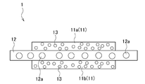
- FIG. 1 is a schematic conceptual view schematically showing the concept of a double-sided pressure-sensitive adhesive tape 1 according to the present technology (hereinafter also referred to as “pressure-sensitive adhesive tape 1”).
- the double-sided pressure-sensitive adhesive tape 1 according to the present technology is used for bonding a pair of adherends to each other, and peels off from the adherend by generating heat by heating.
- At least a conductive heat generating layer 12 provided between the adhesive layers 11 is provided.
- each layer will be described in detail.
- the pressure-sensitive adhesive tape 1 according to the present technology includes a pair of pressure-sensitive adhesive layers 11 bonded to an adherend such as an internal power source such as a battery built in an electronic device or a housing in which the internal power source is stored.
- the pressure-sensitive adhesive tape 1 according to the present technology is disposed between a pair of adherends, and a first pressure-sensitive adhesive layer 11a bonded to one adherend and a second pressure-sensitive adhesive bonded to the other adherend.
- a layer 11b is disposed between a pair of adherends, and a first pressure-sensitive adhesive layer 11a bonded to one adherend and a second pressure-sensitive adhesive bonded to the other adherend.
- each of the adhesive layers 11a and 11b a known material which is usually used for producing a double-sided adhesive tape can be used, for example, an acrylic adhesive having an alkyl (meth) acrylate as a main component. Is mentioned.
- a thermoplastic pressure-sensitive adhesive from the viewpoint of peeling by heating.
- each adhesive layer 11a, 11b is not particularly limited and can be appropriately selected according to the arrangement environment of the adherend bonded by the adhesive tape 1 according to the present technology.
- the lower limit is preferably 30 ⁇ m or more, and more preferably 100 ⁇ m or more.
- the upper limit is preferably 500 ⁇ m or less, and more preferably 300 ⁇ m or less.
- the pressure-sensitive adhesive layer 11 contains a thermal foaming agent 13.
- the thermal foaming agent 13 is foamed by heating, the pressure-sensitive adhesive tape 1 can be peeled off from the adherend. At this time, the foamed thermal foaming agent 13 also functions as a heat insulating material, and prevents heat from propagating from the adhesive layer 11 to the adherend.
- the thermal foaming agent 13 is preferably contained in at least one of the pair of adhesive layers 11. In the adhesive tape 1 shown in FIG. 1, each adhesive layer 11a, 11b An example in which the thermal foaming agent 13 is contained is shown. When the thermal foaming agent 13 is contained in one of the pair of adhesive layers 11a and 11b, the thermal foaming agent 13 is preferably contained in the adhesive layer 11 bonded to the adherend to be positively peeled off.
- the thermal foaming agent 13 is not particularly limited, and for example, a known thermal foaming agent can be appropriately selected and used.
- a known thermal foaming agent can be appropriately selected and used.
- microencapsulated foaming agents various inorganic foaming agents, and organic foaming agents can be used.
- Agents examples of microencapsulated foaming agents are those in which liquefied hydrocarbons are filled into a shell made of polyvinyl chloride, polyvinylidene, etc., and the liquefied hydrocarbons are easily gasified and expanded by heating. Is mentioned.
- representative examples of the inorganic foaming agent include ammonium carbonate, ammonium hydrogen carbonate, sodium hydrogen carbonate, and the like.
- organic foaming agent examples include chlorofluorinated alkanes such as dichloromonofluoromethane; Examples thereof include azo compounds such as isobutyronitrile.
- the expanded thermal foaming agent 13 prevents heat from propagating to the adherend bonded by the pressure-sensitive adhesive tape 1. Microencapsulated blowing agents are preferred.
- the foaming start temperature of the thermal foaming agent 13 is set higher than the temperature (hereinafter referred to as “guaranteed temperature”) equal to or higher than the product reliability guarantee condition of the adherends to be joined by the adhesive tape 1 according to the present technology. It is preferable. In addition, since the foaming start temperature of the thermal foaming agent 13 must ensure the product reliability guarantee condition of the adherend, the foamed thermal foaming agent 13 needs to function as a heat insulating material. It is preferable to set the temperature as low as possible while ensuring a margin for the guaranteed temperature of the body. More specifically, it is preferably set higher in the range of 10 to 50 ° C. than the guaranteed temperature of the adherend, and more preferably set in the range of 10 to 30 ° C. Within the numerical range, when the guaranteed temperature of the adherend is 85 ° C., the foaming start temperature of the thermal foaming agent 13 is preferably set to 100 ° C.
- the pressure-sensitive adhesive tape 1 according to the present technology includes a conductive heating layer 12 between the pair of pressure-sensitive adhesive layers 11.
- heat is transmitted to the pressure-sensitive adhesive layer 11 and the thermal foaming agent 13 is foamed by heating the conductive heat-generating layer 12 to generate heat.
- the interface between the adhesive layer 11 and the adherend is easily peeled off.
- the length of the conductive heat generating layer 12 in the longitudinal direction is the length of the pressure-sensitive adhesive layers 11a and 11b in the longitudinal direction. It is set larger than this. That is, both end surfaces in the longitudinal direction of the conductive heat generating layer 12 protrude from both end surfaces in the longitudinal direction of the adhesive layers 11a and 11b, and the front and back surfaces of the conductive heat generating layer 12 facing in the direction perpendicular to the longitudinal direction are exposed to the external atmosphere. It has been configured.
- the longitudinal length of the conductive heat generation layer 12 is set to be the same as the longitudinal length of the second adhesive layer 11 b, and both end surfaces of the conductive heat generation layer 12 are the adhesive layers. While it arrange
- the conductive heat generating layer 12 is not particularly limited, and examples thereof include a metal film and a resin film including a conductive member 12a inside.
- Examples of the conductive member 12a include heating wire, metal foil, carbon nanotube, carbon powder, and metal powder.
- the metal constituting the metal foil or metal powder is preferably aluminum, copper or the like because of its good conductivity.
- the heating wire is preferably a metal wire having a high electrical resistance, such as a nichrome wire (nickel-chromium alloy metal wire) or an iron-chromium alloy metal wire.
- the method of heating the conductive heat generating layer 12 is not particularly limited, and examples thereof include a method of directly energizing and generating heat using a jig such as a mouth clip and a contact pin, and a method using electromagnetic induction by high frequency. It is done.
- a method of heating the conductive heat generating layer 12 by supplying electric energy directly from the internal power source of the electronic device to the conductive heat generating layer 12. And so on.
- the heat generation temperature of the conductive heat generation layer 12 is preferably set equal to or higher than the foaming start temperature of the thermal foaming agent 13.
- the thermal foaming agent 13 contained in the pressure-sensitive adhesive layer 11 as the heat of the conductive heat generation layer 12 propagates to the pressure-sensitive adhesive layer 11. Therefore, in order to reliably foam the thermal foaming agent 13, it is preferable to set the heat generation temperature of the conductive heat generation layer 12 higher in the range of 10 to 50 ° C. than the foaming start temperature of the thermal foaming agent 13, More preferably, it is set high in the range of 10 to 30 ° C.
- the thickness of the conductive heat generating layer 12 is not particularly limited, and can be appropriately selected according to the arrangement environment of the adherend bonded by the pressure-sensitive adhesive tape 1 according to the present technology.
- the adherend according to the present technology is not particularly limited as long as it is bonded by a double-sided adhesive tape such as the adhesive tape 1 according to the present technology.
- a combination of a pair of adherends in an electronic device such as a personal computer or a mobile phone, a combination of an internal power source such as a battery and a housing or substrate of the electronic device that contacts the internal power source, an optical element, a lens, a prism, Conclude parts and devices that are highly reusable for cost and environmental considerations, such as LCD screens and housings, housings and LCD screens and backlights, housings and substrates and flexible wiring boards, and substrates or housings and film antennas. The part etc. can be considered.
- the adhesive tape 1 is used to bond a pair of adherends to each other.
- the adhered adherend is peeled off and reused, or when the adhered adherend is peeled and repaired, the conductive heating layer 12 protruding from the end face of the adhesive layer 11 is heated.
- the conductive heat generating layer 12 is caused to generate heat.
- the heat of the conductive heat generating layer 12 is propagated to the adhesive layer 11, and the thermal foaming agent 13 contained in the adhesive layer 11 is foamed.
- the interface between the adhesive layer 11 and the adherend can be separated from each other or the contact area of each adhesive layer 11 with respect to the adherend can be reduced. Therefore, the propagation of heat to the adherend is suppressed, and the temperature rise of the adherend can be stopped, thereby preventing the quality of the adherend from deteriorating.
- the heat generation temperature of the conductive heat generation layer 12 is set to be equal to or higher than the foaming start temperature of the thermal foaming agent 13, and the foaming start temperature of the thermal foaming agent 13 is It is set higher than the guaranteed temperature of the kimono. For this reason, by heating the conductive heat generating layer 12, the thermal foaming agent 13 contained in the adhesive layer 11 can be surely foamed, so that the interface between the adhesive layer 11 and the adherend is separated from each other. The contact area of each adhesion layer 11 with respect to a to-be-adhered body can be narrowed.
- the foaming start temperature of the thermal foaming agent 13 is set higher than the guaranteed temperature of the adherend, the thermal foaming is caused by heat being propagated to the adhesive layer 11 due to the heat generation of the conductive heating layer 12.
- the agent 13 is foamed.
- the foamed thermal foaming agent 13 functions as a heat insulating material.
- the temperature rise of the adherend can be stopped, and thus the quality of the adherend can be prevented from deteriorating.
- the conductive heating layer 12 is directly energized using a jig such as a contact pin.
- a jig such as a contact pin.
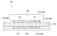
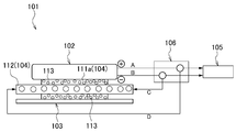
- the electronic device 101 includes an internal power source 102 for driving the electronic device 101, an adherend 103 to which the internal power source 102 is bonded, the internal power source 102 and the adherend 103, and the like. And a double-sided pressure-sensitive adhesive tape 104 for adhering. Further, as necessary, the electronic device 101 according to the present technology includes a driving circuit 105 of the electronic device 101 and a switching unit 106 for supplying electric energy of the internal power supply 102 to the driving circuit 105 or the double-sided adhesive tape 104. And a covering that covers the internal power supply 102 in a state where the internal power supply 102 is accommodated in the adherend 103. The drive circuit 105 and the switching unit 106 will be described later with reference to FIG.
- the electronic device 101 to which the present technology can be applied is not particularly limited and includes known devices such as a notebook personal computer, a PDA (personal digital assistant), a mobile phone, a cordless phone, a video movie, and a digital still camera.
- a notebook personal computer a PDA (personal digital assistant)
- PDA personal digital assistant
- mobile phone a cordless phone
- video movie a digital still camera
- digital still camera Electronic book, electronic dictionary, music player, radio, headphones, game console, navigation system, memory card, pacemaker, hearing aid, electric tool, electric shaver, refrigerator, air conditioner, TV, stereo, water heater, microwave oven, dishwasher, Examples include washing machines, dryers, lighting equipment, toys, medical equipment, robots, road conditioners, traffic lights, and the like.
- the internal power supply 102 included in the electronic device 101 is a battery that uses the electronic device 101 as a drive source.
- the type of the battery is not particularly limited, and examples thereof include a primary battery such as a dry battery, a secondary battery such as a lithium ion secondary battery and a lithium ion polymer secondary battery, and the like.
- Substrate 103 The adherend 103 provided in the electronic device 101 according to the present technology is bonded to the internal power supply 102 via the double-sided adhesive tape 104.
- the internal power supply 102 is fitted and the skeleton of the electronic device 101 is fitted. And a substrate that comes into contact with the internal power supply 102.
- Double-sided adhesive tape 104 The double-sided adhesive tape 104 provided in the electronic device 101 according to the present technology includes a first adhesive layer 111a that is bonded to the internal power supply 102, a second adhesive layer 111b that is bonded to the adherend 103, and a first adhesive layer 111b.
- the conductive heating layer 112 sandwiched between the adhesive layer 111a and the second adhesive layer 111b.
- the basic configuration of the first adhesive layer 111a and the second adhesive layer 111b is the same as that of the adhesive layer 11 included in the adhesive tape 1 according to the present technology, and thus the description thereof is omitted here.
- the thermal foaming agent 113 is contained in at least one of the first adhesive layer 111a and the second adhesive layer 111b, and the quality deterioration of the internal power supply 102 is prevented.
- the thermal foaming agent 113 is contained in the first adhesive layer 111 a that adheres to the internal power supply 102.
- the foaming start temperature of the thermal foaming agent 113 is preferably set higher than the guaranteed temperature of the internal power supply 102.
- the foaming start temperature of the thermal foaming agent 113 must ensure the product reliability guarantee condition of the internal power supply 102, the foamed thermal foaming agent 113 needs to function as a heat insulating agent. It is preferable to set the temperature as low as possible while ensuring a margin with respect to the guaranteed temperature of 102.
- the basic configuration of the conductive heat generating layer 112 is the same as the configuration of the conductive heat generating layer 12 provided in the pressure-sensitive adhesive tape 1 according to the present technology, and the description thereof is omitted here.
- the conductive heat generating layer 112 may include a conductive member 112a. Since the conductive member 112a is the same as the conductive member 12a included in the conductive heat generating layer 12, the description thereof is omitted here.
- the heat generation temperature of the conductive heat generation layer 112 is preferably set equal to or higher than the foaming start temperature of the thermal foaming agent 113.
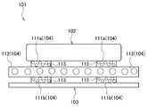
- the double-sided adhesive tape 104 is disposed between the internal power source 102 and the adherend 103, and the first adhesive layer 111 a is connected to the internal power source 102.
- the second adhesive layer 111 b is used so as to adhere to the adherend 103.
- both end surfaces of the conductive heat generating layer 112 protrude from both end surfaces of the adhesive layers 111a and 111b, and the surface of the conductive heat generating layer 112 facing the direction perpendicular to the longitudinal direction is the internal power source.
- the back surface faces the adherend 103.
- the longitudinal length of the conductive heat generating layer 112 is set to be the same as the longitudinal length of the first adhesive layer 111a, as shown in FIG.
- the both ends of the conductive heat generating layer 112 are arranged on the same plane as the both ends of the first adhesive layer 111a, but may protrude from the end surface of the second adhesive layer 111b.
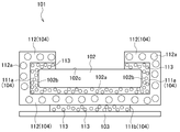
- the first adhesive layer 111a faces the adherend 103, the inner side surface 102a of the internal power source 102, a part of both side surfaces 102b of the internal power source 102, and the inner power source 102 that faces the covering. It is preferable to adhere to the outer side surface 102c.
- the conductive heat generating layer 112 since the longitudinal length of the conductive heat generating layer 112 is set to be the same as the longitudinal length of the first adhesive layer 111a, the conductive heat generating layer 112 includes the inner side surface 102a of the internal power source 102, It bends so as to cover both side surfaces 102b and the outer surface 102c, and is exposed on the outer surface 102c side of the internal power supply 102.
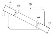
- two double-sided adhesive tapes 104 can be bonded along the longitudinal direction of the internal power supply 102 and arranged in parallel to each other.
- two internal power sources 102 can be bonded in a direction perpendicular to the longitudinal direction and arranged in parallel to each other.
- the double-sided pressure-sensitive adhesive tape 104 can be adhered to the internal power supply 102 while being inclined with respect to the longitudinal direction.
- the double-sided pressure-sensitive adhesive tape 104 shown in FIG. 7 has the form shown in FIG. 4, and the conductive heat generation layer 112 is exposed on the outer side surface 102 c side of the internal power supply 102.
- the electronic device 101 may include a drive circuit 105 for driving the electronic device 101.
- the drive circuit 105 is a normal drive circuit mounted on the electronic device 101, and a known configuration can be adopted.
- the electronic device 101 may include a switching unit 106 that switches a supply destination of the electrical energy stored in the internal power source 102.
- the switching unit 106 is configured to supply the electric energy of the internal power supply 102 to the driving circuit 105 when the electronic device 101 is driven (arrows A and B).
- the electric energy of the internal power source 102 is supplied to the conductive heat generating layer 112 of the double-sided adhesive tape 104 (arrow line). C and D).
- the configuration of the switching unit 106 is not particularly limited, and a known unit used when switching the supply destination of electrical energy in the circuit board can be applied.
- a mechanical switch such as a slide switch or a push switch can be used.
- a short land is installed in the substrate pattern portion constituting the switching unit 106, and when the electronic device 101 is driven, the short lands on the drive circuit 105 side are short-circuited with solder and electric energy is supplied, while the internal power supply 102 is peeled off. In this case, the short land solder on the drive circuit 105 side may be removed and soldered to the short land on the conductive heat generating layer 112 side.
- the inventor of the present technology manufactures an electronic device including a double-sided pressure-sensitive adhesive tape having a conductive heat generating layer between a pair of pressure-sensitive adhesive layers and a pair of pressure-sensitive adhesive layers, and heats the conductive pressure-sensitive adhesive layer.
- an evaluation was made as to whether or not the double-sided pressure-sensitive adhesive tape was peeled off from the adherend.
- a thermal foaming agent having a foaming start temperature of 100 ° C. and a thermal foaming agent contained in each adhesive layer were produced.
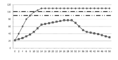
- thermocouple was provided in the interface of the said battery and the adhesion layer, and the interface of the said adhesion layer and a conductive heat generating layer, and the temperature change in each interface according to progress of heating time was measured.
- FIG. 10 The measurement results are shown in FIG. In FIG. 10, the vertical axis represents temperature, and the horizontal axis represents energization heating time (seconds). Moreover, the dashed-dotted line in FIG. 10 shows the foaming start temperature of a thermal foaming agent, and a dashed-two dotted line shows the guarantee temperature of a battery. Further, a square plot indicates the temperature at the interface between the battery and the adhesive layer, and a circle plot indicates the temperature at the interface between the adhesive layer and the conductive heat generating layer. As shown in FIG. 10, even when the conductive heat generating layer is heated and the temperature at the interface between the adhesive layer and the conductive heat generating layer becomes higher than the foaming start temperature 100 ° C.
- the temperature at the interface with the adhesive layer was lower than the guaranteed battery temperature of 85 ° C. That is, in the double-sided pressure-sensitive adhesive tape according to the present technology, it was confirmed that the battery can be peeled from the copper substrate in a temperature state where the temperature of the battery is lower than the foaming start temperature of the thermal foaming agent. Moreover, it was confirmed that the thermal foaming agent contained in the adhesive layer functions as a heat insulating agent, and the heat propagated from the conductive heat generating layer to the adhesive layer is not transmitted to the battery.
- the electronic device 101 when the internal power supply 102 is peeled off from the adherend 103, the conductive heat generating layer 112 protruding from the end face of the adhesive layer 111 is heated, thereby The heat generating layer 112 generates heat. Thereby, the heat of the conductive heat generating layer 112 is propagated to the adhesive layer 111 and the thermal foaming agent 113 contained in the adhesive layer 111 is foamed. For this reason, the interface between the adhesive layer 111 and the internal power source 102 is separated, or the contact area of each adhesive layer 111 with respect to the internal power source 102 can be reduced.
- the thermal foaming agent 113 is foamed, the heat of the conductive heat generating layer 112 can be prevented from propagating to the internal power source 102.
- the temperature rise of the internal power supply 102 can be stopped, and quality deterioration of the internal power supply 102 can be prevented.
- the electronic device 101 by providing the switching unit 106, it is not necessary to supply electric energy from the outside of the electronic device 101, and the electronic device 101 has a simple configuration correspondingly. be able to.
- one adhesive layer 111 is provided on one surface of the conductive heat generating layer 112.
- the number of layers 111 is not particularly limited, and a plurality of layers 111 can be provided.
- two adhesive layers 111 may be provided on one surface of the conductive heat generating layer 112.
- Disassembly structure The present technology also provides a structure for disassembling a pair of adhered adherends.
- This dismantling structure includes a double-sided pressure-sensitive adhesive tape and a pair of adherends bonded via the double-sided pressure-sensitive adhesive tape.
- the double-sided adhesive tape includes a pair of adhesive layers and a conductive heat generating layer provided between the pair of adhesive layers, and at least one of the pair of adhesive layers includes a thermal foaming agent, The end face of the conductive heating layer protrudes from the end face of at least one adhesive layer.
- the adhesive layer containing the said thermal foaming agent can be foam-expanded by heating the end surface of the said conductive heat generating layer, and a pair of adherend can be disassembled.
- the structure of the double-sided pressure-sensitive adhesive tape included in the disassembly structure according to the present technology is the same as the structure of the double-sided pressure-sensitive adhesive tape 1 described above, the description thereof is omitted here.
- the adherend with which the disassembly structure which concerns on this technique is provided is the same as the adherend in which the double-sided adhesive tape 1 mentioned above is used, the description is omitted here.
- Adhesive structure Conventionally, in the adhesive structure in which the first adhesive body and the second adhesive body are bonded, when peeling the first adhesive body or the second adhesive body, using a thermostatic bath or a dryer, Means for heating the entire adhesive structure is employed. In recent years, there has been a tendency to increase the demand for reuse of recycled resources. In electronic devices including an internal power source such as a battery as an adhesive or a cover glass constituting an image display surface, the manufactured battery, cover glass, etc. It is disassembled and collected for each component material. However, in the conventional heating means, the first adhesive body and / or the second adhesive body is damaged by heating, and the first adhesive body and / or the second adhesive body cannot be reused. There was a problem.
- the present technology is capable of peeling the first adhesive body and / or the second adhesive body without damaging the first adhesive body and / or the second adhesive body.
- a structure having an adhesive layer for adhering one adhesive and a second adhesive will be described with reference to FIGS.
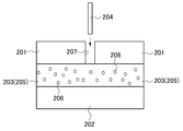
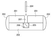
- the bonding structure includes a first bonding body 201, a second bonding body 202 bonded to the first bonding body, and an adhesive layer 203 that bonds the first bonding body 201 and the second bonding body 202. And at least.
- This adhesive structure may include a jig 204 for peeling the adhesive layer 203 from the first adhesive body 201 or the second adhesive body 202 as necessary.
- First adhesive body 201 and second adhesive body 202 It does not specifically limit as the 1st adhesive body 201 and the 2nd adhesive body 202 which concern on this technique, A well-known adhesive body can be used.
- a well-known adhesive body can be used as a combination of the first adhesive body 201 and the second adhesive body 202.
- Adhesive layer 203 The adhesive structure according to the present technology includes an adhesive layer 203 for adhering the first adhesive body 201 and the second adhesive body 202. It does not specifically limit as an adhesive agent for shape
- the self-disassembling adhesive layer 205 refers to an adhesive layer that peels itself from the first adhesive body 201 and / or the second adhesive body 202, for example, an adhesive layer containing a thermal foaming agent 206. It is done.
- the thermal foaming agent 206 is not particularly limited, and for example, a known thermal foaming agent can be appropriately selected and used.
- microencapsulated foaming agents, various inorganic foaming agents, and organic foaming agents can be used.
- Agents examples of microencapsulated foaming agents are those in which liquefied hydrocarbons are filled in a shell made of polyvinyl chloride, polyvinylidene, etc., and the liquefied carbon hydrogen expands easily by gasification by heating. Is mentioned.
- representative examples of the inorganic foaming agent include ammonium carbonate, ammonium hydrogen carbonate, sodium hydrogen carbonate, and the like.
- Representative examples of the organic foaming agent include chlorofluorinated alkanes such as dichloromonofluoromethane; Examples thereof include azo compounds such as isobutyronitrile.
- the foaming start temperature of the thermal foaming agent 206 is set to be higher than the temperature (hereinafter referred to as “guaranteed temperature”) equal to or higher than the product reliability guarantee condition of the first adhesive body 201 and / or the second adhesive body 202. It is preferable that the foaming start temperature of the thermal foaming agent 13 is such that the thermal foaming agent 206 serves as a heat insulating agent while ensuring the product reliability guarantee conditions of the first adhesive body 201 and / or the second adhesive body 202. Since it is necessary to make it function, it is preferable to set the temperature as low as possible while ensuring a margin with respect to the guaranteed temperature of the adherend. More specifically, it is preferably set higher in the range of 10 to 50 ° C. than the guaranteed temperature of the first adhesive body 201 and / or the second adhesive body 202, more preferably 10 to 30 ° C. Set higher in range.
- the thermal foaming agent 206 contained in the self-disassembling adhesive layer 205 is foamed, and the adhesive layer 203 itself is the first adhesive body. 201 and / or the second adhesive 202 is peeled off.
- the method for heating the self-decomposing adhesive layer 205 is not particularly limited, and examples thereof include a method of generating heat by directly energizing using a jig, a method using electromagnetic induction by high frequency, and the like.
- the adhesive structure according to the present technology may include a jig 204 for heating the self-decomposing adhesive layer 205.
- the jig 204 is not particularly limited as long as it is a jig that applies heat to the object, and a known jig can be used.
- Examples of the jig 204 according to the present technology include a tool provided with at least a heating part inserted into the self-decomposing adhesive layer 205 and an internal power source for supplying electric energy to the heating part.
- the heating unit is made of, for example, a thin rod-like or needle-like metal material, and is configured to be supplied with electrical energy from the internal power source.
- the heating unit generates heat by electric energy supplied from the internal power source.
- a metal member that forms such a heating unit it is preferable to use a material having high thermal conductivity, and examples thereof include copper, brass, and aluminum.
- examples of the structure for heating the heating unit include a structure in which an energized heating material such as a nichrome wire is wound around the heating unit, and a structure in which the heating unit is burned with gas.
- the tip of the heating part formed in a thin rod shape or needle shape may be configured so as to heat the self-disassembling adhesive layer 205, for example, when heating only the surface of the self-disassembling adhesive layer 205.
- the tip portion may be formed in a planar shape. Or when inserting and heating a front-end
- the tip portion is pointed and a heating part is inserted into the self-dismantling adhesive layer 205. Is preferred.
- the adhesive structure according to the present technology configured as described above, by heating the self-dismantling adhesive layer 205, the thermal foaming agent 206 contained in the self-dismantling adhesive layer 205 foams, and the adhesive layer 203 peels itself from the first adhesive body 201 and / or the second adhesive body 202. Therefore, unlike the conventional case, it is not necessary to heat the entire bonding structure, and the first bonding body 201 and / or the second bonding body 202 is not damaged without damaging the first bonding body 201 and / or the second bonding body 202. Alternatively, the second adhesive 202 can be peeled off. As a result, the first adhesive 201 and / or the second adhesive 202 can be reused.
- the entire adhesive layer 203 is formed as the self-disassembling adhesive layer 205, but the configuration of the adhesive layer 203 is not limited to this. That is, it is sufficient that the first adhesive body 201 and / or the second adhesive body 202 can be provided with an opportunity to peel the adhesive layer 203 by itself, and as described above, a part of the adhesive layer 203 is removed by the self-disassembly.
- the adhesive layer 205 can be formed. In such a case, the strength of the adhesive layer 203 as a whole can be improved by using an adhesive other than the self-disassembling adhesive layer 205 having a high hardness.
- an adhesive other than the self-decomposing adhesive layer 205 as a known adhesive, the entire adhesive layer 203 can be manufactured at low cost.
- the bonding structure according to the second embodiment is different from the first bonding body according to the first embodiment in the structure of the first bonding body 201.
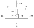
- the other configurations are common, description on the other configurations is omitted here. That is, in the bonding structure according to the second embodiment, a jig insertion hole 207 into which the jig 204 is inserted is formed in the first adhesive body 201. All the jig insertion holes 207 are opened toward the adhesive layer 203 which is the self-disassembling adhesive layer 205.
- the jig 204 is inserted into the jig insertion hole 207, and the adhesive layer 203 (self-decomposing adhesive layer 205) is heated using the jig 204. Can do.
- the thermal foaming agent 206 contained in the self-disassembling adhesive layer 205 foams, and the adhesive layer 203 peels itself from the first adhesive body 201 and / or the second adhesive body 202. . For this reason, it is not necessary to heat the whole adhesion structure like the past, and it can peel without damaging to the 1st adhesion body 201 and / or the 2nd adhesion body 202.
- the first adhesive 201 and / or the second adhesive 202 can be reused.
- the present technology when the present technology is applied as an adhesive structure in an electronic device such as a mobile phone, it may be difficult to heat the self-disassembling adhesive layer 205 from the left and right of the adhesive structure as shown in FIG. In such a case, the self-disassembling adhesive layer 205 can be heated by providing the jig insertion hole 207.
- the jig insertion hole 207 is formed in the first bonding body 201, and the jig insertion hole 207 corresponds to the first bonding body 201 or the second bonding body 201. If it is formed on at least one of the bodies 202, it does not matter. Further, in the bonding structure shown in FIG. 12, one jig insertion hole 207 is formed in the first bonding body 201, but the number of the jig insertion holes 207 is not limited, and the bonding body 201, A plurality may be formed for 202. Furthermore, in the adhesive structure shown in FIG.
- the entire adhesive layer 203 is formed as a self-disassembling adhesive layer 205, but the adhesive layer 203 is attached to the first adhesive 201 and / or the second adhesive 202.
- a part of the adhesive layer 203 continuous with the jig insertion hole 207 may be formed as the self-disassembling adhesive layer 205 as long as it can provide an opportunity to peel off itself.
- the arrangement of the adhesive layer 203 is different from the arrangement of the adhesive layer according to the first embodiment shown in FIG.
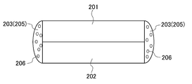
- the adhesive layers 203 are provided on both end faces of the first adhesive body 201 and both end faces of the second adhesive body 202, and the first adhesive body 201 and The second adhesive 202 is so-called potting bonded.
- Each adhesive layer 203 is formed as a self-disassembling adhesive layer 205.
- the thermal foaming agent 206 contained in the self-decomposing adhesive layer 205 is foamed, and the adhesive layer 203 is heated. Is peeled off from the first adhesive body 201 and / or the second adhesive body 202 itself. For this reason, it is not necessary to heat the whole adhesion structure like the past, and it can peel without damaging to the 1st adhesion body 201 and / or the 2nd adhesion body 202. As a result, the first adhesive 201 and / or the second adhesive 202 can be reused.
- the entire adhesive layer 203 is formed as a self-disassembling adhesive layer 205, but the configuration of the adhesive layer 203 is not limited to this, and the first adhesive 201 In addition, it is only necessary to provide an opportunity for the adhesive layer 203 to be peeled from the second adhesive body 202, and a part of the adhesive layer 203 may be used as the self-disassembling adhesive layer 205.
- the first bonding body 201 and the second bonding body 202 are so-called potting bonded.
- the self-disassembling adhesive layer 205 is separated from the first adhesive 201 and the second adhesive 202 with certainty. As shown in FIG. 15, it is preferably disposed on the interface between the first adhesive body 201 and the second adhesive body 202. In such a configuration, the first adhesive body 201 and the second adhesive body 202 can be reliably peeled off. Moreover, the strength of the adhesive layer 203 as a whole can be improved by using an adhesive other than the self-disassembling adhesive layer 205 having a high hardness. In addition, by using an adhesive other than the self-decomposing adhesive layer 205 as a known adhesive, the entire adhesive layer 203 can be manufactured at low cost.
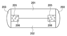
- the bonding method between the first bonding body 201 and the second bonding body 202 and the structure of the first bonding body 201 are different from the bonding structure shown in FIG.
- symbol is attached
- the first bonding body 201 and the second bonding body 202 are bonded via the bonding layer 203 and the self-disassembling bonding layer 205.
- Adhesive layers 203 are provided on both end faces of the first adhesive body 201 and both end faces of the second adhesive body 202, and the first adhesive body 201 and the second adhesive body 202 are so-called potted. .
- an adhesive layer 203 is provided on the interface between the first adhesive body 201 and the second adhesive body 202, and the adhesive layer 203 is formed as a self-disassembling adhesive layer 205.
- a jig insertion hole 207 communicating with the self-decomposing adhesive layer 205 is formed in the first adhesive body 201, and the jig 204 is inserted into the jig insertion hole 207. It has become.
- the thermal foaming agent 206 contained in the self-decomposing adhesive layer 205 is foamed, and the first The adhesive 201 and the second adhesive 202 can be peeled from each other. For this reason, it is not necessary to heat the whole adhesion structure like the past, and it can peel without damaging to the 1st adhesion body 201 and / or the 2nd adhesion body 202. As a result, the first adhesive 201 and / or the second adhesive 202 can be reused.
- This technology can also take the following composition.
- An end surface of the conductive heat generating layer is a double-sided pressure-sensitive adhesive tape protruding from an end surface of at least one adhesive layer.
- the foaming start temperature of the thermal foaming agent is set higher than the guaranteed temperature of the adherend bonded to the adhesive layer,
- An electronic device comprising at least an internal power source that drives the electronic device, an adherend that adheres to the internal power source, and a double-sided adhesive tape that adheres the internal power source and the adherend,
- the double-sided pressure-sensitive adhesive tape is provided between the first pressure-sensitive adhesive layer bonded to the internal power source, the second pressure-sensitive adhesive layer bonded to the adherend, and the first pressure-sensitive adhesive layer and the second pressure-sensitive adhesive layer.
- An electrically conductive heating layer Either one of the first adhesive layer or the second adhesive layer contains a thermal foaming agent, The electronic device, wherein an end face of the conductive heat generating layer protrudes from an end face of one of the first adhesive layer and the second adhesive layer.
- the foaming start temperature of the thermal foaming agent contained in the double-sided pressure-sensitive adhesive tape is set higher than the guaranteed temperature of the internal power supply
- the end face of the conductive heat generating layer projects from the end face of the second adhesive layer, and is disposed on the same plane as the end face of the first adhesive layer.
- the first adhesive layer is bonded to the inner surface of the internal power source facing the adherend and the outer surface of the internal power source facing the covering covering the internal power source.
- the electronic device according to any one of (10) The electronic device according to any one of (5) to (9), further including a switching unit that supplies electric energy supplied from the internal power source to the electronic device to the conductive heat generation layer.
- Double-sided adhesive tape A pair of adherends bonded via the double-sided adhesive tape
- the double-sided pressure-sensitive adhesive tape comprises a pair of adhesive layers and a conductive heat generating layer provided between the pair of adhesive layers, At least one of the pair of adhesive layers includes a thermal foaming agent, The end face of the conductive heating layer protrudes from the end face of at least one adhesive layer, A disassembly structure in which a pair of adherends are disassembled by heating and foaming the adhesive layer containing the thermal foaming agent by heating an end face of the conductive heat generating layer.
- An adhesive structure having an adhesive layer that bonds the first adhesive body and the second adhesive body, The adhesive structure has a self-disassembling adhesive layer in contact with at least one of the first adhesive body or the second adhesive body.
- a jig insertion hole communicating with the self-disassembling adhesive layer is formed in at least one of the first adhesive body or the second adhesive body.
Abstract
Description
構造に関する。
また、温度耐久性の低い部品が接着される場面では、粘着テープの剥離後、当該部品を再利用せずに廃棄することが前提とされていた。
この両面粘着テープにおいて、前記熱発泡剤の発泡開始温度は、前記粘着層に接着される被着体の保証温度よりも高く設定され、前記導電発熱層の発熱温度は、前記発泡開始温度と同一又は高く設定されていてもよい。
この両面粘着テープにおいて、前記導電発熱層の端面は、一方の粘着層の端面よりも突出し、他方の粘着層の端面と同一平面上に配されていてもよい。
この両面粘着テープにおいて、各粘着層が熱発泡剤を含んでいてもよい。
この電子機器において、前記両面粘着テープに含有される熱発泡剤の発泡開始温度は、前記内部電源の保証温度よりも高く設定され、前記導電発熱層の発熱温度は、前記発泡開始温度と同一又は高く設定されていてもよい。
この電子機器において、前記導電発熱層の端面は、前記第二の粘着層の端面よりも突出し、前記第一の粘着層の端面と同一平面上に配されていてもよい。
この電子機器において、前記第一の粘着層は熱発泡剤を含んでいてもよい。
この電子機器において、前記第一の粘着層は、前記被着体と対面する内部電源の内側面、及び前記内部電源を覆う被覆体と対面する当該内部電源の外側面に接着されていてもよい。
この電子機器において、更に、前記内部電源から前記電子機器へと供給される電気エネルギーを前記導電発熱層へと供給する切り替え部を備えていてもよい。
前記導電発熱層の端面は、少なくとも一方の粘着層の端面よりも突出し、前記導電発熱層の端面を加熱することにより、前記熱発泡剤を含む粘着層を発泡させて一対の被着体を解体させる解体構造をも提供する。
この接着構造において、前記第一の接着体又は第二の接着体の少なくとも一方には、前記自己解体性接着層に連通する治具挿入孔が形成されていてもよい。
なお、ここに記載された効果は、必ずしも限定されるものではなく、本技術中に記載されたいずれかの効果であってもよい。
1.両面粘着テープ1
(1)粘着層11
(2)熱発泡剤13
(3)導電発熱層12
(4)被着体
2.電子機器101
(1)内部電源102
(2)被着体103
(3)両面粘着テープ104
(4)駆動回路105
(5)切り替え部106
(6)両面粘着テープの評価
3.解体構造
4.接着構造
(1)第一の接着体201及び第二の接着体202
(2)接着層203
(3)治具204
図1は、本技術に係る両面粘着テープ1(以下、「粘着テープ1」ともいう)の概念を模式的に示す模式概念図である。本技術に係る両面粘着テープ1は、一対の被着体同士を接着するために用いられ、加熱により発熱することにより前記被着体から剥離するものであり、一対の粘着層11と、一対の粘着層11の間に設けられる導電発熱層12を少なくとも備える。以下、各層について詳細に説明する。
本技術に係る粘着テープ1は、例えば電子機器に内蔵されるバッテリ等の内部電源や、当該内部電源が収納される筐体などの被着体に接着される一対の粘着層11を備える。
本技術に係る粘着テープ1は、一対の被着体の間に配され、一方の被着体に接着される第一の粘着層11aと、他方の被着体に接着される第二の粘着層11bと、を備える。
知の材料を用いることができ、例えば、アルキル(メタ)アクリレートを主成分とするようなアクリル系粘着剤などが挙げられる。本技術に係る粘着テープ1では、加熱により剥離させると言う観点から、熱可塑系の粘着剤を用いることが好ましい。
着される被着体の配置環境に応じて適宜選定することができるが、被着体に対する本技術に係る粘着テープ1の剥離に要する時間を短くするため、その下限値は、好ましくは30μm以上であり、更に好ましくは100μm以上である。上限値は、好ましくは500μm以下であり、更に好ましくは300μm以下である。
また、本技術に係る両面粘着テープ1では、前記粘着層11が熱発泡剤13を含有する。加熱によりこの熱発泡剤13が発泡することにより、前記粘着テープ1が被着体から剥離することができるようになっている。この際、発泡した熱発泡剤13は断熱材としても機能し、粘着層11から被着体へ熱が伝播することを防止している。
本技術に係る粘着テープ1において、熱発泡剤13は一対の粘着層11の少なくとも一方に含有されることが好ましい。図1に示す粘着テープ1では、各粘着層11a,11b
に対して熱発泡剤13が含有された例が示されている。この熱発泡剤13を一対の粘着層11a,11bの何れか一方に含有させる場合には、積極的に剥離させたい被着体に接着
される粘着層11に含有させることが好ましい。
加えて、前記熱発泡剤13の発泡開始温度は、被着体の製品信頼性保証条件を確保しつつも、発泡した熱発泡剤13が断熱材として機能する必要があることから、前記被着体の保証温度に対して余裕度を確保しながら極力低い温度に設定することが好ましい。
より具体的には、前記被着体の保証温度よりも10~50℃の範囲で高く設定することが好ましく、より好ましくは10~30℃の範囲で高く設定する。その数値範囲の中でも、被着体の保証温度を85℃とした場合、熱発泡剤13の発泡開始温度は100℃に設定することが好ましい。
本技術に係る粘着テープ1は、前記一対の粘着層11の間に導電発熱層12を備える。本技術に係る粘着テープ1では、前記導電発熱層12を加熱し、発熱させることにより、前記粘着層11に熱が伝播して前記熱発泡剤13が発泡する。その結果、粘着層11と被着体との界面が容易に剥離される。
すなわち、前記導電発熱層12の長手方向両端面は、各粘着層11a,11bの長手方向両端面よりも突出し、長手方向と垂直な方向に面する導電発熱層12の表裏面は外部雰囲気に露出された構成となっている。
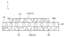
尚、図1に示す粘着テープ1では、前記導電発熱層12の端面が各粘着層11a,11bの端面よりも突出した構成となっているが、本技術に係る粘着テープ1の構成はこれに限定されず、例えば、図2に示すように、導電発熱層12の長手方向長さが第二の粘着層11bの長手方向長さと同一に設定され、当該導電発熱層12の両端面が前記粘着層11bの両端面と同一平面上に配される一方、第一の粘着層11aの端面から突出した構成としても差し支えない。
このため、前記熱発泡剤13を確実に発泡させるためには、導電発熱層12の発熱温度が前記熱発泡剤13の発泡開始温度よりも10~50℃の範囲で高く設定することが好ましく、より好ましくは10~30℃の範囲で高く設定する。
なお、導電発熱層12の発熱温度が上記範囲よりも高い温度に設定されると、導電発熱層12を発熱させた際、粘着テープ1全体の温度が被着体の保証温度を越えてしまい、前記被着体の品質劣化を招くおそれがあるため好ましくない。なお、導電発熱層12の厚さは特に限定されず、本技術に係る粘着テープ1により接着される被着体の配置環境に応じて適宜選定することができる。
本技術に係る被着体としては、本技術に係る粘着テープ1のような両面粘着テープにより接着されるものであれば特に限定されない。一対の被着体の組み合わせとしては、パソコンや携帯電話等の電子機器における、バッテリ等の内部電源と当該内部電源に接触する電子機器の筐体や基板との組み合わせや光学素子とレンズやプリズム,液晶画面と筐体,筐体や液晶画面とバックライト,筐体や基板とフレキシブル配線板,基板または筐体とフィルムアンテナなど、コストや環境面配慮で再利用する価値が高い部品・デバイスの締結部などが考えられる。
そして、接着された被着体を剥離して再利用する場合や、接着された被着体を剥離して修理する場合、前記粘着層11の端面から突出した導電発熱層12を加熱することにより、当該導電発熱層12を発熱させる。これにより、斯かる導電発熱層12の熱が粘着層11に伝播し、粘着層11に含有された熱発泡剤13が発泡することとなる。その結果、粘着層11と被着体との界面が互いに離間又は被着体に対する各粘着層11の接触面積を狭小化させることできる。それ故、被着体への熱の伝播が抑制されて被着体の温度上昇を停止させることができ、もって被着体の品質劣化を防ぐことができる。
次に、本技術を適用した電子機器について、図3及び図4を用いて説明する。図3及び4に示される電子機器101は、当該電子機器101を駆動させるための内部電源102と、当該内部電源102が接着される被着体103と、前記内部電源102と被着体103とを接着する両面粘着テープ104と、を少なくとも備える。また、必要に応じて、本技術に係る電子機器101は、当該電子機器101の駆動回路105と、前記内部電源102の電気エネルギーを駆動回路105又は両面粘着テープ104に供給するための切り替え部106と、前記被着体103に内部電源102が収容された状態で、当該内部電源102を覆う被覆体と、を備えていてもよい。尚、駆動回路105及び切り替え部106については図8を用いて後述する。
本技術に係る電子機器101が備える内部電源102は、当該電子機器101を駆動源となるバッテリである。バッテリの種類は特に限定されず、例えば、乾電池等の一次電池や、リチウムイオン二次電池やリチウムイオンポリマー二次電池等の二次電池等が挙げられる。
本技術に係る電子機器101が備える被着体103は、前記両面粘着テープ104を介して前記内部電源102と接着されるものであり、例えば、前記内部電源102が嵌ると共に前記電子機器101の骨格となる筐体や、前記内部電源102に当接される基板などが挙げられる。
本技術に係る電子機器101が備える両面粘着テープ104は、前記内部電源102に接着される第一の粘着層111aと、前記被着体103に接着される第二の粘着層111bと、第一の粘着層111aと第二の粘着層111bに挟持される導電発熱層112と、を備える。
その一方で、本技術に係る電子機器101では、第一の粘着層111a及び第二の粘着層111bの少なくとも一方に熱発泡剤113が含有されていればよく、内部電源102の品質劣化の防止等を考慮すると、前記熱発泡剤113は内部電源102に接着する第一の粘着層111aに含有されていることが好ましい。
また、前記熱発泡剤113の発泡開始温度は、前記内部電源102の保証温度よりも高く設定されていることが好ましい。加えて、前記熱発泡剤113の発泡開始温度は、内部電源102の製品信頼性保証条件を確保しつつも、発泡した熱発泡剤113が断熱剤として機能する必要があることから、前記内部電源102の保証温度に対して余裕度を確保しながら極力低い温度に設定することが好ましい。
更に、前記導電発熱層112は導電部材112aを含んでいてもよい。この導電部材112aは前記導電発熱層12に含まれる導電部材12aと同一であるため、ここではその説明を割愛する。
その一方で、導電発熱層112の発熱温度は、前記熱発泡剤113の発泡開始温度と同一又は高く設定することが好ましい。
っており、長手方向と垂直な方向に面する導電発熱層112の表面は前記内部電源102に、裏面は前記被着体103に対面するようになっている。
かかる場合、前記導電発熱層112の長手方向長さが第一の粘着層111aの長手方向長さと同一に設定されていることから、前記導電発熱層112は、前記内部電源102の内側面102a、両側面102b及び外側面102cを覆うようにして屈曲し、内部電源102の外側面102c側にて露出するようになる。
図5に示すように、前記両面粘着テープ104は、前記内部電源102の長手方向に沿って二つ接着させ、且つ、互いに平行に配置することができる。
また図6に示すように、前記内部電源102の長手方向と垂直な方向に二つ接着させ、且つ、互いに平行に配置することもできる。
更に図7に示すように、内部電源102の長手方向に対して傾斜させて前記両面粘着テープ104を接着させることも可能である。ここで、図7に示す両面粘着テープ104は、図4に示す形態であり、導電発熱層112が内部電源102の外側面102c側に露出している。
図8に示すように、本技術に係る電子機器101は、当該電子機器101を駆動させるための駆動回路105を備えていてもよい。かかる駆動回路105は、電子機器101に搭載される通常の駆動回路であって、その構成は公知のものを採用することができる。
図8に示すように、本技術に係る電子機器101は、内部電源102に蓄積されている電気エネルギーの供給先を切り替える切り替え部106を備えていてもよい。この切り替え部106では、電子機器101を駆動させる際、前記内部電源102の電気エネルギーが前記駆動回路105に供給するように構成されている(矢線A及びB)。その一方、前記内部電源102を被着体103から剥離させる際には、前記内部電源102の電気エネルギーが前記両面粘着テープ104の導電発熱層112に供給されるように構成されている(矢線C及びD)。
また、切り替え部106を構成する基板パターン部にショートランドを設置し、電子機器101の駆動時は前記駆動回路105側ショートランドをはんだでショートさせて電気エネルギーを供給する一方、内部電源102を剥離する際には前記駆動回路105側のショートランドはんだを除去し、前記導電発熱層112側へのショートランドへはんだ付けを行う構成も挙げられる。
更に、電子機器101の駆動時用の端子やコネクターと、内部電源102の剥離時用の端子やコネクターと、を設け、内部電源102からのフレキシブル配線板又はハーネスの接続先を変更する構成なども挙げられる。
本技術の発明者は、一対の粘着層及び一対の粘着層の間に導電発熱層を有する両面粘着テープを備えた電子機器を製造し、前記導電粘着層を加熱することにより、前記両面粘着テープが被着体から剥離するか否かについての評価を行った。
更に、導電粘着層の熱が粘着層を介して被着体に伝播されるか否かについて評価を行った。
前記両面粘着テープとしては、前記熱発泡剤として、その発泡開始温度が100℃であるものを用い、且つ、この熱発泡剤を各粘着層に含有させたものを製造した。
また、前記電子機器の内部電源としてバッテリを、前記被着体として銅製基板を用いた。更に、前記バッテリの保証温度を85℃と設定した。
そして、前記バッテリと粘着層との界面、及び前記粘着層と導電発熱層との界面に熱電対を設け、加熱時間の経過に応じた各界面における温度変化を測定した。
この図10に示すように、前記導電発熱層を加熱し、前記粘着層と導電発熱層との界面の温度が熱発泡剤の発泡開始温度100℃よりも高温になったとしても、前記バッテリと粘着層との界面の温度はバッテリの保証温度85℃よりも低い温度を示した。
すなわち、本技術に係る両面粘着テープでは、前記バッテリの温度が熱発泡剤の発泡開始温度を下回る温度状態において、当該バッテリを銅製基板から剥離することができる点が確認された。
また、粘着層に含有される熱発泡剤が断熱剤として機能し、導電発熱層から粘着層へと伝播した熱がバッテリに伝播されていないことが確認された。
このため、粘着層111と内部電源102との界面が離間又は内部電源102に対する各粘着層111の接触面積を狭小化させることできる。また、前記熱発泡剤113が発泡することで、前記導電発熱層112の熱が内部電源102に伝播することを防ぐことができる。
その結果、前記内部電源102を被着体103から剥離する際、当該内部電源102の温度上昇を停止させることができ、もって内部電源102の品質劣化を防ぐことができる。
本技術は、接着された一対の被着体同士を解体するための構造をも提供する。この解体構造は、両面粘着テープと、前記両面粘着テープを介して接着される一対の被着体と、を備えている。
また、前記両面粘着テープは、一対の粘着層と、一対の粘着層の間に設けられる導電発熱層と、を備えており、一対の粘着層のうち少なくとも一方は、熱発泡剤を含み、前記導電発熱層の端面は、少なくとも一方の粘着層の端面よりも突出している。
そして、本技術に係る解体構造では、前記導電発熱層の端面を加熱することにより、前記熱発泡剤を含む粘着層を発泡膨張させ、一対の被着体を解体させることができる。
また、本技術に係る解体構造が備える被着体は、前述した両面粘着テープ1が用いられる被着体と同一であるため、ここではその説明を割愛する。
従来、第一の接着体と第二の接着体とが接着された接着構造において、第一の接着体又は第二の接着体を剥離する際には、恒温槽やドライヤーを用いて、前記接着構造全体を加熱する手段が採用されている。
近年、再生資源の再利用の要求が高まる傾向にあり、接着体としてのバッテリ等の内部電源や画像表示面を構成するカバーガラスなどを備える電子機器等において、製造されたバッテリやカバーガラス等を分解して構成材料毎に回収している。
しかし、従来の加熱手段では、第一の接着体及び/又は第二の接着体に対して加熱による損傷を与え、第一の接着体及び/又は第二の接着体を再利用することができないといった課題があった。
以下、この接着構造について、図11~図16を用いて説明する。当該接着構造は、第一の接着体201と、当該第一の接着体に接着される第二の接着体202と、第一の接着体201と第二の接着体202を接着する接着層203と、を少なくとも備える。この接着構造は、必要に応じて、前記接着層203を第一の接着体201又は第二の接着体202から剥離させるための治具204を備えていてもよい。
本技術に係る第一の接着体201及び第二の接着体202としては、特に限定されず、公知の接着体を用いることができる。第一の接着体201及び第二の接着体202の組み合わせとしては、携帯電話等を骨格となる筐体と当該筐体に積層され、前記携帯電話の画像表示面を形成するカバーガラスとの組み合わせや、筐体と筐体の貼り合わせ,液晶表示画面と筐体やバックライトの貼り合わせ,基板と筐体の貼り合わせ、また、携帯電話以外の大型電気機器における筐体と筐体の貼り合わせ,筐体と各種デバイスや基板の貼り合わせなどが挙げられる。
本技術に係る接着構造は、前記第一の接着体201と第二の接着体202とを接着させるための接着層203を備える。この接着層203を成形するための接着剤としては特に限定されず、公知の接着剤を用いることができる。また、この接着層203の全部又は一部は、自己解体性接着層205として形成されており、この自己解体性接着層205は前記第一の接着体201又は第二の接着体202の少なくとも一方に接している。図11に示す形態では、前記接着層203の全部が自己解体性接着層205として形成され、且つ、当該接着層が第一の接着体201と第二の接着体202との間に配されている例を示している。
加えて、前記熱発泡剤13の発泡開始温度は、第一の接着体201及び/又は第二の接着体202の製品信頼性保証条件を確保しつつも、当該熱発泡剤206が断熱剤として機能させる必要があることから、前記被着体の保証温度に対して余裕度を確保しながら極力低い温度に設定することが好ましい。
より具体的には、第一の接着体201及び/又は第二の接着体202の保証温度よりも10~50℃の範囲で高く設定されていることが好ましく、より好ましくは10~30℃の範囲で高く設定する。
本技術に係る接着構造では、前記自己解体性接着層205を加熱することにより、当該自己解体性接着層205に含有された熱発泡剤206が発泡し、接着層203が自ら第一の接着体201及び/又は第二の接着体202から剥離するようになっている。
前記自己解体性接着層205を加熱する方法としては、特に限定されず、治具を用いて直接通電して発熱させる方法や高周波による電磁誘導を利用した方法等が挙げられる。
ここで、前記自己解体性接着層205に含有される熱発泡剤206を確実に発泡させるためには、前記先端部を尖頭状とし、自己解体性接着層205の内部に加熱部を差し込むことが好ましい。
すなわち、第一の接着体201及び/又は第二の接着体202に対して接着層203を自ら剥離させる契機を与えることができればよく、前述の如く、前記接着層203の一部を前記自己解体性接着層205とすることができる。
かかる場合には、自己解体性接着層205以外の接着剤として硬度が高いものを用いることにより接着層203全体の強度を向上させるができる。また、自己解体性接着層205以外の接着剤を公知の接着剤とすることにより、接着層203全体を安価に製造することができる。
すなわち、この第二の実施形態に係る接着構造では、前記治具204が挿入される治具挿入孔207が第一の接着体201に形成されている。前記治具挿入孔207は全部が自己解体性接着層205である接着層203に向けて開口されている。
また、携帯電話等の電子機器内の接着構造として本技術を適用する場合、図11に示すように、自己解体性接着層205を接着構造の左右から加熱することが困難となり得る。かかる場合には、前記治具挿入孔207を設けることにより、前記自己解体性接着層205を加熱することができる。
更に、図12に示す接着構造では、前記接着層203全体が自己解体性接着層205として形成されているが、第一の接着体201及び/又は第二の接着体202に対して接着層203を自ら剥離させる契機を与えることができればよく、図13に示すように、前記治具挿入孔207と連続する接着層203の一部を前記自己解体性接着層205として形成しても差し支えない。
すなわち、この第三の実施形態に係る接着構造では、第一の接着体201の両端面と第二の接着体202の両端面に対して接着層203が設けられ、第一の接着体201と第二の接着体202とが所謂ポッティング接着されている。
そして、各接着層203は全部が自己解体性接着層205として形成されている。
図14に示す接着構造では、第一の接着体201と第二の接着体202とが所謂ポッティング接着されている。この構成において前記接着層203の一部を前記自己解体性接着層205にする場合、第一の接着体201と第二の接着体202と確実に剥離させるため、自己解体性接着層205は、図15に示すように、第一の接着体201と第二の接着体202との界面上に配置されることが好ましい。
このような構成とした場合、第一の接着体201と第二の接着体202と確実に剥離させることができる。また、自己解体性接着層205以外の接着剤として硬度が高いものを用いることにより接着層203全体の強度を向上させるができる。また、自己解体性接着層205以外の接着剤を公知の接着剤とすることにより、接着層203全体を安価に製造することができる。
更に、第一の接着体201と第二の接着体202との界面上に接着層203が設けられ、当該接着層203が自己解体性接着層205として形成されている。
また、前記第一の接着体201には、前記自己解体性接着層205に連通する治具挿入孔207が形成されており、当該治具挿入孔207には前記治具204が挿入されるようになっている。
(1)
一対の粘着層と、一対の粘着層の間に設けられる導電発熱層と、を備え、
一対の粘着層のうち少なくとも一方は、熱発泡剤を含み、
前記導電発熱層の端面は、少なくとも一方の粘着層の端面よりも突出する、両面粘着テープ。
(2)
前記熱発泡剤の発泡開始温度は、前記粘着層に接着される被着体の保証温度よりも高く設定され、
前記導電発熱層の発熱温度は、前記発泡開始温度と同一又は高く設定される、(1)に記載の両面粘着テープ。
(3)
前記導電発熱層の端面は、一方の粘着層の端面よりも突出し、他方の粘着層の端面と同一平面上に配される、(1)又は(2)に記載の両面粘着テープ。
(4)
各粘着層が熱発泡剤を含む、(1)~(3)の何れか一つに記載の両面粘着テープ。
(5)
電子機器を駆動させる内部電源と、前記内部電源と接着する被着体と、前記内部電源と被着体とを接着する両面粘着テープと、を少なくとも備える電子機器であって、
前記両面粘着テープは、前記内部電源に接着される第一の粘着層と、前記被着体に接着される第二の粘着層と、第一の粘着層と第二の粘着層の間に設けられる導電発熱層と、を備え、
第一の粘着層又は第二の粘着層のいずれか一方は、熱発泡剤を含み、
前記導電発熱層の端面は、第一の粘着層又は第二の粘着層のいずれか一方の粘着層の端面よりも突出する、電子機器。
(6)
前記両面粘着テープに含有される熱発泡剤の発泡開始温度は、前記内部電源の保証温度よりも高く設定され、
前記導電発熱層の発熱温度は、前記発泡開始温度と同一又は高く設定される、(5)に記載の電子機器。
(7)
前記導電発熱層の端面は、前記第二の粘着層の端面よりも突出し、前記第一の粘着層の端面と同一平面上に配される、(5)又は(6)に記載の電子機器。
(8)
前記第一の粘着層は熱発泡剤を含む、(5)~(7)の何れか一つに記載の電子機器。(9)
前記第一の粘着層は、前記被着体と対面する内部電源の内側面、及び前記内部電源を覆う被覆体と対面する当該内部電源の外側面、に接着される、(5)~(8)の何れか一つに記載の電子機器。
(10)
更に、前記内部電源から前記電子機器へと供給される電気エネルギーを前記導電発熱層へと供給する切り替え部を備える、(5)~(9)の何れか一つに記載の電子機器。
(11)
両面粘着テープと、
前記両面粘着テープを介して接着される一対の被着体と、を備え、
前記両面粘着テープは、一対の粘着層と、一対の粘着層の間に設けられる導電発熱層と、を備え、
一対の粘着層のうち少なくとも一方は、熱発泡剤を含み、
前記導電発熱層の端面は、少なくとも一方の粘着層の端面よりも突出し、
前記導電発熱層の端面を加熱することにより、前記熱発泡剤を含む粘着層を発泡膨張させて一対の被着体を解体させる解体構造。
(12)
第一の接着体と第二の接着体とを接着する接着層を有する接着構造であって、
前記接着層は、前記第一の接着体又は第二の接着体の少なくとも一方に接する自己解体性接着層を有する、接着構造。
(13)
前記第一の接着体又は第二の接着体の少なくとも一方には、前記自己解体性接着層に連通する治具挿入孔が形成されている、(12)に記載の接着構造。
11,111,111a,111b 粘着層
12,112 導電発熱層
13,113 熱発泡剤
101 電子機器
102 内部電源
103 被着体
Claims (13)
- 一対の粘着層と、一対の粘着層の間に設けられる導電発熱層と、を備え、
一対の粘着層のうち少なくとも一方は、熱発泡剤を含み、
前記導電発熱層の端面は、少なくとも一方の粘着層の端面よりも突出する、両面粘着テープ。 - 前記熱発泡剤の発泡開始温度は、前記粘着層に接着される被着体の保証温度よりも高く設定され、
前記導電発熱層の発熱温度は、前記発泡開始温度と同一又は高く設定される、請求項1に記載の両面粘着テープ。 - 前記導電発熱層の端面は、一方の粘着層の端面よりも突出し、他方の粘着層の端面と同一平面上に配される、請求項2に記載の両面粘着テープ。
- 各粘着層が熱発泡剤を含む、請求項3に記載の両面粘着テープ。
- 電子機器を駆動させる内部電源と、前記内部電源と接着する被着体と、前記内部電源と被着体とを接着する両面粘着テープと、を少なくとも備える電子機器であって、
前記両面粘着テープは、前記内部電源に接着される第一の粘着層と、前記被着体に接着される第二の粘着層と、第一の粘着層と第二の粘着層の間に設けられる導電発熱層と、を備え、
第一の粘着層又は第二の粘着層のいずれか一方は、熱発泡剤を含み、
前記導電発熱層の端面は、第一の粘着層又は第二の粘着層のいずれか一方の粘着層の端面よりも突出する、電子機器。 - 前記両面粘着テープに含有される熱発泡剤の発泡開始温度は、前記内部電源の保証温度よりも高く設定され、
前記導電発熱層の発熱温度は、前記発泡開始温度と同一又は高く設定される、請求項5に記載の電子機器。 - 前記導電発熱層の端面は、前記第二の粘着層の端面よりも突出し、前記第一の粘着層の端面と同一平面上に配される、請求項6に記載の電子機器。
- 前記第一の粘着層は熱発泡剤を含む、請求項7に記載の電子機器。
- 前記第一の粘着層は、前記被着体と対面する内部電源の内側面、及び前記内部電源を覆う被覆体と対面する当該内部電源の外側面、に接着される、請求項8に記載の電子機器。
- 更に、前記内部電源から前記電子機器へと供給される電気エネルギーを前記導電発熱層へと供給する切り替え部を備える、請求項9に記載の電子機器。
- 両面粘着テープと、
前記両面粘着テープを介して接着される一対の被着体と、を備え、
前記両面粘着テープは、一対の粘着層と、一対の粘着層の間に設けられる導電発熱層と、を備え、
一対の粘着層のうち少なくとも一方は、熱発泡剤を含み、
前記導電発熱層の端面は、少なくとも一方の粘着層の端面よりも突出し、
前記導電発熱層の端面を加熱することにより、前記熱発泡剤を含む粘着層を発泡膨張させて一対の被着体を解体させる解体構造。 - 第一の接着体と第二の接着体とを接着する接着層を有する接着構造であって、
前記接着層は、前記第一の接着体又は第二の接着体の少なくとも一方に接する自己解体性接着層を有する接着構造。 - 前記第一の接着体又は第二の接着体の少なくとも一方には、前記自己解体性接着層に連通する治具挿入孔が形成されている、請求項12に記載の接着構造。
Priority Applications (4)
| Application Number | Priority Date | Filing Date | Title |
|---|---|---|---|
| CN201680012920.2A CN107835844A (zh) | 2015-07-21 | 2016-04-20 | 双面粘合带,具有双面粘合带的电子设备,具有双面粘合带的拆卸结构和粘合结构 |
| DE112016003292.7T DE112016003292B4 (de) | 2015-07-21 | 2016-04-20 | Doppelseitiges Klebeband und Verwendung |
| JP2017529476A JP6264509B2 (ja) | 2015-07-21 | 2016-04-20 | 両面粘着テープ、当該両面粘着テープを備える電子機器、前記両面粘着テープを備えた解体構造、接着構造 |
| US15/554,165 US11306223B2 (en) | 2015-07-21 | 2016-04-20 | Double-sided adhesive tape, electronic instrument provided with double-sided adhesive tape, disassembly structure provided with double-sided adhesive tape, and adhered structure |
Applications Claiming Priority (2)
| Application Number | Priority Date | Filing Date | Title |
|---|---|---|---|
| JP2015144213 | 2015-07-21 | ||
| JP2015-144213 | 2015-07-21 |
Publications (1)
| Publication Number | Publication Date |
|---|---|
| WO2017013914A1 true WO2017013914A1 (ja) | 2017-01-26 |
Family
ID=57834286
Family Applications (1)
| Application Number | Title | Priority Date | Filing Date |
|---|---|---|---|
| PCT/JP2016/062477 WO2017013914A1 (ja) | 2015-07-21 | 2016-04-20 | 両面粘着テープ、当該両面粘着テープを備える電子機器、前記両面粘着テープを備えた解体構造、接着構造 |
Country Status (5)
| Country | Link |
|---|---|
| US (1) | US11306223B2 (ja) |
| JP (2) | JP6264509B2 (ja) |
| CN (1) | CN107835844A (ja) |
| DE (1) | DE112016003292B4 (ja) |
| WO (1) | WO2017013914A1 (ja) |
Cited By (3)
| Publication number | Priority date | Publication date | Assignee | Title |
|---|---|---|---|---|
| WO2020023138A1 (en) * | 2018-07-23 | 2020-01-30 | Microsoft Technology Licensing, Llc | Pressure sensitive adhesive with thermally conductive release tab |
| CN111630698A (zh) * | 2017-12-18 | 2020-09-04 | 三星Sdi株式会社 | 终止带及包括其的二次电池 |
| US11611125B2 (en) * | 2018-01-17 | 2023-03-21 | Lg Energy Solution, Ltd. | Battery module housing having easily reusable, recyclable, and reworkable adhesion structure and battery module comprising same |
Families Citing this family (3)
| Publication number | Priority date | Publication date | Assignee | Title |
|---|---|---|---|---|
| US11683986B2 (en) * | 2017-11-13 | 2023-06-20 | Asahi Fr R&D Co., Ltd. | Thermoeletric conversion device |
| CN109971387B (zh) * | 2017-12-28 | 2021-01-22 | 清华大学 | 碳纳米管结构作为双面胶的应用 |
| CN112787033A (zh) * | 2021-01-29 | 2021-05-11 | 东莞新能德科技有限公司 | 热减粘保护膜及应用其的电子装置 |
Citations (3)
| Publication number | Priority date | Publication date | Assignee | Title |
|---|---|---|---|---|
| JP2012117041A (ja) * | 2010-11-12 | 2012-06-21 | Nitto Denko Corp | 粘着剤組成物、粘着剤層、及び、粘着テープ又はシート |
| JP2013045036A (ja) * | 2011-08-26 | 2013-03-04 | Seiko Instruments Inc | 粘着ラベル及びラベル発行装置 |
| JP2015074764A (ja) * | 2013-10-11 | 2015-04-20 | アキレス株式会社 | 熱剥離性粘着フィルム |
Family Cites Families (17)
| Publication number | Priority date | Publication date | Assignee | Title |
|---|---|---|---|---|
| SE439599B (sv) * | 1981-01-14 | 1985-06-24 | Kema Nord Ab | Sett att torka och expandera i vetska dispergerade, termoplastiska mikrosferer innehallande, flyktiga, flytande jesmedel |
| JPH04198289A (ja) | 1990-11-26 | 1992-07-17 | Sekisui Chem Co Ltd | 片面または両面接着発泡体テープの製造方法 |
| JP3452972B2 (ja) | 1994-04-08 | 2003-10-06 | 三福工業株式会社 | フッ素ゴム発泡体の製造方法 |
| JPH11293207A (ja) | 1998-04-03 | 1999-10-26 | Nitto Denko Corp | 加熱消失性粘着シート |
| JP2001323228A (ja) * | 2000-05-15 | 2001-11-22 | Nitto Denko Corp | 加熱剥離型粘着シート |
| JP2004099758A (ja) | 2002-09-10 | 2004-04-02 | Nitto Denko Corp | 両面粘着テープおよび接着方法 |
| JP2005101094A (ja) | 2003-09-22 | 2005-04-14 | Sekisui Chem Co Ltd | 表面に回路パターンが形成された基板及び焼結性を有するセラミックグリーンシート及び多層セラミック基板の製造方法 |
| JP4704017B2 (ja) | 2004-12-09 | 2011-06-15 | 日東電工株式会社 | 被着物の加熱剥離方法及び被着物加熱剥離装置 |
| JP2007023113A (ja) | 2005-07-14 | 2007-02-01 | Asahi Kasei Chemicals Corp | 両面接着フィルム、接着方法及び接着構造体 |
| JP5171425B2 (ja) | 2007-10-22 | 2013-03-27 | 日東電工株式会社 | 加熱発泡型再剥離性アクリル系粘着テープ又はシート、及び剥離方法 |
| JP5173753B2 (ja) | 2008-11-11 | 2013-04-03 | 日東電工株式会社 | 解体構造、解体構造を有する電気機器および非電気機器、並びに解体方法 |
| JP5546985B2 (ja) | 2010-07-28 | 2014-07-09 | 日東電工株式会社 | 半導体装置製造用フィルム、半導体装置製造用フィルムの製造方法、及び、半導体装置の製造方法。 |
| JP2013133464A (ja) | 2011-12-27 | 2013-07-08 | Nitto Denko Corp | ガラス板用粘着シート |
| JP2013159743A (ja) | 2012-02-07 | 2013-08-19 | Nitto Denko Corp | 粘着剤積層物の剥離方法およびそれに用いる粘着剤層 |
| US20140287299A1 (en) | 2013-03-25 | 2014-09-25 | Apple Inc. | Heat-Debonding Adhesives |
| JP2015034265A (ja) * | 2013-08-09 | 2015-02-19 | 日東電工株式会社 | 易解体型両面粘着シート、及びその貼付方法 |
| CN103474596B (zh) | 2013-09-16 | 2016-01-13 | 惠州Tcl移动通信有限公司 | 一种移动终端软包电池的固定装置、固定方法及移动终端 |
-
2016
- 2016-04-20 JP JP2017529476A patent/JP6264509B2/ja active Active
- 2016-04-20 WO PCT/JP2016/062477 patent/WO2017013914A1/ja active Application Filing
- 2016-04-20 DE DE112016003292.7T patent/DE112016003292B4/de active Active
- 2016-04-20 CN CN201680012920.2A patent/CN107835844A/zh active Pending
- 2016-04-20 US US15/554,165 patent/US11306223B2/en active Active
-
2017
- 2017-12-21 JP JP2017245089A patent/JP6973032B2/ja active Active
Patent Citations (3)
| Publication number | Priority date | Publication date | Assignee | Title |
|---|---|---|---|---|
| JP2012117041A (ja) * | 2010-11-12 | 2012-06-21 | Nitto Denko Corp | 粘着剤組成物、粘着剤層、及び、粘着テープ又はシート |
| JP2013045036A (ja) * | 2011-08-26 | 2013-03-04 | Seiko Instruments Inc | 粘着ラベル及びラベル発行装置 |
| JP2015074764A (ja) * | 2013-10-11 | 2015-04-20 | アキレス株式会社 | 熱剥離性粘着フィルム |
Cited By (4)
| Publication number | Priority date | Publication date | Assignee | Title |
|---|---|---|---|---|
| CN111630698A (zh) * | 2017-12-18 | 2020-09-04 | 三星Sdi株式会社 | 终止带及包括其的二次电池 |
| US11611125B2 (en) * | 2018-01-17 | 2023-03-21 | Lg Energy Solution, Ltd. | Battery module housing having easily reusable, recyclable, and reworkable adhesion structure and battery module comprising same |
| WO2020023138A1 (en) * | 2018-07-23 | 2020-01-30 | Microsoft Technology Licensing, Llc | Pressure sensitive adhesive with thermally conductive release tab |
| US11084955B2 (en) | 2018-07-23 | 2021-08-10 | Microsoft Technology Licensing, Llc | Pressure sensitive adhesive with thermally conductive release tab |
Also Published As
| Publication number | Publication date |
|---|---|
| US11306223B2 (en) | 2022-04-19 |
| CN107835844A (zh) | 2018-03-23 |
| JP6973032B2 (ja) | 2021-11-24 |
| DE112016003292T5 (de) | 2018-04-12 |
| DE112016003292B4 (de) | 2024-03-28 |
| JP2018087335A (ja) | 2018-06-07 |
| JPWO2017013914A1 (ja) | 2017-12-07 |
| JP6264509B2 (ja) | 2018-01-24 |
| US20180291237A1 (en) | 2018-10-11 |
Similar Documents
| Publication | Publication Date | Title |
|---|---|---|
| JP6264509B2 (ja) | 両面粘着テープ、当該両面粘着テープを備える電子機器、前記両面粘着テープを備えた解体構造、接着構造 | |
| US20140287299A1 (en) | Heat-Debonding Adhesives | |
| EP3128503A1 (en) | Display device, display module and display member | |
| JP5175746B2 (ja) | 多層フレキシブル回路基板 | |
| US20150289358A1 (en) | Heat radiation printed circuit board, method of manufacturing the same, backlight unit including the same, and liquid crystal display device | |
| CN101742190A (zh) | 拆卸构造、具有它的电气设备和非电气设备、及拆卸方法 | |
| CN113692130A (zh) | 一种fpc结构及其制作方法 | |
| CN106255317A (zh) | 一种方便拼接耐用型hdi柔性线路板及其加工工艺 | |
| CN107801303B (zh) | 一种柔性电路板 | |
| JP6204020B2 (ja) | 熱拡散部材および熱拡散部材を備える電子機器 | |
| JP2007234830A (ja) | フレキシブル配線基板の導通接合構造 | |
| TW200626040A (en) | Thermal bonding structure and manufacture process of flexible printed circuit (FPC) | |
| JP5525017B2 (ja) | 解体構造および解体構造を有する非電気機器 | |
| JP4202295B2 (ja) | リフローはんだ付け装置 | |
| JPWO2007023534A1 (ja) | 表示パネル装置 | |
| CN104075179A (zh) | 背光模组及使用该背光模组的显示装置 | |
| JP2004134301A (ja) | プレスフィット端子圧入方法及びその圧入用治具 | |
| CN215647605U (zh) | 一种fpc结构 | |
| CN209676599U (zh) | 一种可焊接串联的软性线路板 | |
| JP4985927B2 (ja) | 表示装置 | |
| KR100659102B1 (ko) | 플라즈마 디스플레이 장치 | |
| JP2009158833A (ja) | フレキシブルプリント配線基板の接続構造 | |
| JP2012195765A (ja) | 端子カバー | |
| JP2008158291A (ja) | 点灯検査装置 | |
| JP2014154810A (ja) | 筺体の接着構造及びそれを用いた情報端末 |
Legal Events
| Date | Code | Title | Description |
|---|---|---|---|
| 121 | Ep: the epo has been informed by wipo that ep was designated in this application |
Ref document number: 16827478 Country of ref document: EP Kind code of ref document: A1 |
|
| ENP | Entry into the national phase |
Ref document number: 2017529476 Country of ref document: JP Kind code of ref document: A |
|
| WWE | Wipo information: entry into national phase |
Ref document number: 15554165 Country of ref document: US |
|
| WWE | Wipo information: entry into national phase |
Ref document number: 112016003292 Country of ref document: DE |
|
| 122 | Ep: pct application non-entry in european phase |
Ref document number: 16827478 Country of ref document: EP Kind code of ref document: A1 |