WO2017010510A1 - 破砕機 - Google Patents
破砕機 Download PDFInfo
- Publication number
- WO2017010510A1 WO2017010510A1 PCT/JP2016/070677 JP2016070677W WO2017010510A1 WO 2017010510 A1 WO2017010510 A1 WO 2017010510A1 JP 2016070677 W JP2016070677 W JP 2016070677W WO 2017010510 A1 WO2017010510 A1 WO 2017010510A1
- Authority
- WO
- WIPO (PCT)
- Prior art keywords
- rotary
- screen
- attached
- shaft
- shafts
- Prior art date
Links
Images


Classifications
-
- B—PERFORMING OPERATIONS; TRANSPORTING
- B02—CRUSHING, PULVERISING, OR DISINTEGRATING; PREPARATORY TREATMENT OF GRAIN FOR MILLING
- B02C—CRUSHING, PULVERISING, OR DISINTEGRATING IN GENERAL; MILLING GRAIN
- B02C18/00—Disintegrating by knives or other cutting or tearing members which chop material into fragments
- B02C18/06—Disintegrating by knives or other cutting or tearing members which chop material into fragments with rotating knives
- B02C18/14—Disintegrating by knives or other cutting or tearing members which chop material into fragments with rotating knives within horizontal containers
-
- B—PERFORMING OPERATIONS; TRANSPORTING
- B02—CRUSHING, PULVERISING, OR DISINTEGRATING; PREPARATORY TREATMENT OF GRAIN FOR MILLING
- B02C—CRUSHING, PULVERISING, OR DISINTEGRATING IN GENERAL; MILLING GRAIN
- B02C18/00—Disintegrating by knives or other cutting or tearing members which chop material into fragments
- B02C18/06—Disintegrating by knives or other cutting or tearing members which chop material into fragments with rotating knives
- B02C18/16—Details
- B02C18/22—Feed or discharge means
-
- B—PERFORMING OPERATIONS; TRANSPORTING
- B02—CRUSHING, PULVERISING, OR DISINTEGRATING; PREPARATORY TREATMENT OF GRAIN FOR MILLING
- B02C—CRUSHING, PULVERISING, OR DISINTEGRATING IN GENERAL; MILLING GRAIN
- B02C18/00—Disintegrating by knives or other cutting or tearing members which chop material into fragments
- B02C18/06—Disintegrating by knives or other cutting or tearing members which chop material into fragments with rotating knives
- B02C18/16—Details
- B02C18/24—Drives
Definitions
- the present invention relates to a crusher that crushes objects to be processed such as wood and garbage.
- This application claims priority in Japanese Patent Application No. 2015-141390 for which it applied on July 15, 2015, and uses the content here.
- a crusher has been used as a means for crushing to-be-processed objects such as wood (for example, wood for biomass power generation), bamboo, and combustible / noncombustible waste.
- wood for example, wood for biomass power generation
- bamboo for example, bamboo
- combustible / noncombustible waste combustible waste.
- rotary crushers, shear crushers, biaxial shear crushers, and the like are known.
- Each crusher has a rotary blade that is attached to a rotating shaft and has a plurality of crushing blades formed in the circumferential direction.
- a crusher is also known in which a screen is provided below a rotary blade in order to make a crushed material generated by crushing an object to be processed into a predetermined size (particle size) (see, for example, Patent Document 1). ).
- a plurality of regularly formed opening holes are formed in the screen, and the crushed material continues to be crushed by a rotary blade passing on the screen to a size that can pass through the opening holes.
- An object of the present invention is to provide a crusher capable of improving the processing efficiency of a workpiece and reducing the load on a rotating shaft.
- the crusher is a pair of rotary shafts arranged in parallel to each other, and a plurality of rotary blades attached to each of the rotary shafts with an interval in the axial direction.
- a plurality of rotary blades wherein a rotary blade attached to one of the rotary shafts and a rotary blade attached to the other of the rotary shafts are attached so as to partially overlap the rotation locus when viewed from the axial direction of the rotary shaft
- a screen that receives the crushed material outside the rotation trajectory of the plurality of rotary blades attached to one of the rotating shafts and drops the crushed material having a predetermined size or less, and the pair of the screens At least a part of the end portion in the arrangement direction of the rotation shafts is arranged on the inner peripheral side with respect to the rotation locus of the rotation blade attached to the other rotation shaft.
- the crushed material that does not need to pass through the screen is discharged from the other rotating shaft side without stagnation, the crushed material is discharged compared to the case where the screens are provided on both rotating shafts.
- the processing efficiency of the processed product can be improved.
- the screen is not installed on the other rotating shaft side, the load applied to the other rotating shaft by the crushed material staying on the screen can be reduced. Further, by retaining the long object to be processed that has passed between the rotary blades on the screen, it is possible to prevent the long object to pass through.
- the crusher may include a plurality of spacers attached to the rotary shaft alternately in the axial direction with the rotary blade, and the screen may extend to an outer peripheral surface of the spacer.
- the rotation speed of one of the rotation shafts may be lower than the rotation speed of the other rotation shaft.
- surplus power of the rotating shaft with less load can be used for crushing using the rotary blade and the screen.
- the object to be processed is compared with the case where screens are provided on both rotating shafts.
- the processing efficiency can be improved.
- the screen is not installed on the other rotating shaft side, the load applied to the other rotating shaft by the crushed material staying on the screen can be reduced.
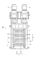
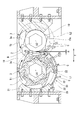
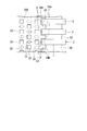
- FIG. 2 is a cross-sectional view taken along line X1-X1 in FIG. 1, showing a crusher. It is the figure which looked at the rotary blade of 1st embodiment of this invention, the spacer, and the screen from the axial direction of the rotating shaft. It is a top view of the screen of 1st embodiment of this invention. It is the figure which looked at the screen of 1st embodiment of this invention from the axial direction of the rotating shaft. It is a figure explaining the effect
- the crusher of 1st embodiment of this invention is demonstrated in detail with reference to drawings.
- the crusher of this embodiment is, for example, a biaxial shear crusher that crushes to-be-processed objects (waste) such as wood, bamboo, and garbage into a crushed material of a predetermined size (length, particle size) ( A multiaxial shearing crusher).
- the crusher of this embodiment is particularly suitable for crushing wood materials and bamboo materials that contain a large amount of long objects to be processed.
- the crusher 100 includes a casing 25, a pair of crushing mechanisms 4, a screen 20 that receives an object to be processed crushed by the crushing mechanism 4 and drops it downward. It is equipped with.
- the crushing mechanism 4 includes a pair of rotary shafts 1 and 2 arranged in parallel with each other inside the casing 25, and a plurality of rotary blades 3 attached to the rotary shafts 1 and 2 with an interval in the axial direction. And a plurality of spacers 10 attached between the rotary blades 3 adjacent to each other in the axial direction of the rotary shaft 1 and a drive device 5 such as an electric motor for rotating the rotary shafts 1 and 2.
- a drive device 5 such as an electric motor for rotating the rotary shafts 1 and 2.
- one rotating shaft 1 is referred to as a first rotating shaft 1
- the other rotating shaft is referred to as a second rotating shaft 2.
- the first rotating shaft 1 and the second rotating shaft 2 of the present embodiment are each driven by a driving device 5.
- the first rotating shaft 1 is set to rotate in the T1 direction in FIG. 3, and the second rotating shaft 2 is set to rotate in the T2 direction in FIG.
- the 1st rotating shaft 1 and the 2nd rotating shaft 2 can rotate not only in the T1 direction of FIG. 3, but the T2 direction, and a reverse direction. For example, when a large load is applied to the driving device 5 during crushing, it can be rotated in the reverse direction.
- the drive device 5 can arbitrarily set the rotation speed of the output shaft. That is, the first rotating shaft 1 and the second rotating shaft 2 can be rotated at a desired rotational speed. In the crusher 100 of the present embodiment, the first rotating shaft 1 is rotated at a low speed, and the second rotating shaft 2 is rotated at a higher speed than the first rotating shaft 1. That is, the rotation speed of the first rotation shaft 1 and the rotation speed of the second rotation shaft 2 are different, and the rotation speed of the first rotation shaft 1 is lower than the rotation speed of the second rotation shaft 2. It should be noted that, using one driving device 5 and a gear mechanism that transmits the driving force of the driving device 5 to the two rotating shafts 1 and 2, the two rotating shafts 1 and 2 are connected using one driving device 5. It may be configured to drive.
- the first rotating shaft 1 and the second rotating shaft 2 have a hexagonal cross-sectional shape as shown in FIG. 3, and are rotated around the axes O 1 and O 2 by the driving device 5.
- the cross-sectional shape of the 1st rotating shaft 1 and the 2nd rotating shaft 2 should just be a cross-sectional polygonal shape, for example, is good also as square shape.
- the rotary shafts 1 and 2 may have a circular cross section and may be fixed using the spacer 10 and the rotary blade 3 and a key.
- the scraper 21 is provided from the side wall of the casing 25 toward a position facing the rotary blade 3 and the spacer 10.
- the scraper 21 prevents the object to be processed from falling between the rotary blade 3 and the casing 25 or scrapes off the object to be processed sandwiched between the rotary blades 3.
- the scraper 21 is formed in a comb-teeth shape when viewed from above so as to allow passage of the rotary blade 3.
- the tip of the scraper 21 is formed in a semicircular arc shape so as to be close to the peripheral surfaces of the rotary blade 3 and the spacer 10.
- the axes O1 and O2 of the first rotating shaft 1 and the second rotating shaft 2 are parallel.
- the direction along the axes O1 and O2 is simply referred to as an axial direction A.
- a horizontal direction orthogonal to the axial direction A is referred to as a width direction Y of the rotary shafts 1 and 2.
- the width direction Y is an arrangement direction in which the rotation axes 1 and 2 are arranged.
- the rotary blades 3 and the spacers 10 are alternately arranged in the axial direction A.
- the width (thickness) in the axial direction A of the rotary blade 3 and the width in the axial direction A of the spacer 10 are the same.
- the rotary blades 3 and the spacers 10 attached to the first rotary shaft 1 and the rotary blades 3 and the spacers 10 attached to the second rotary shaft 2 are arranged so as to alternate in the axial direction A. .
- the rotary blade 3 attached to the first rotary shaft 1 and the spacer 10 attached to the second rotary shaft 2 adjacent to the first rotary shaft 1 have the same position in the axial direction A. It is arranged to be.
- a part of the rotation locus of the rotary blade 3 attached to the first rotary shaft 1 and a part of the rotation locus of the rotary blade 3 attached to the second rotary shaft 2 are overlapped when viewed from the axial direction A. ing.
- the crusher 100 shears and crushes the workpiece by rotating the rotary blade 3 around the axes O1 and O2 together with the rotary shafts 1 and 2 of each crushing mechanism 4.
- the rotary blade 3 is inserted into the polygonal center hole 3a with the rotary shafts 1 and 2 fitted therein, and is fixed to the rotary shafts 1 and 2 while being coaxially arranged on the rotary shafts 1 and 2.
- a crushing blade 7 which is detachably attached to the outer periphery of the blade receiving base 6 with a cutting blade portion 9 disposed radially outside the centers of the axes O1 and O2 and arranged in parallel in the circumferential direction of the centers of the axes O1 and O2. It is configured with.
- the trajectory drawn by the tip of the cutting edge portion 9 of the rotary blade 3 attached to the rotary shafts 1 and 2 is referred to as rotation trajectories L1 and L2.
- a semi-cylindrical screen 20 having a plurality of opening holes 22 through which the pulverized material crushed to a predetermined size is passed. . Only the crushed material that has been crushed to such a size as to pass through the opening hole 22 falls downward through the screen 20.
- the screen 20 receives the crushed material crushed by the crushing mechanism 4 outside the rotation locus L1 of the plurality of rotary blades 3 provided on the first rotary shaft 1.
- the screen 20 includes a curved surface portion 30 having a curved plate shape, a bracket portion 26 provided on one side in the width direction Y of the curved surface portion 30, and the other side in the width direction Y of the curved surface portion 30. And a plurality of extensions 24 provided in the.
- a side of the curved surface portion 30 opposite to the bracket portion 26 is supported by a predetermined support member 27.
- the curved surface portion 30 extends in the axial direction A and has a cross-sectional shape that forms an arc shape when viewed from the axial direction A.
- the curved curvature of the curved surface portion 30 is smaller than the curvature of the rotation locus L1.
- the center of curvature of the main surface 30 a of the curved surface portion 30 of the present embodiment substantially coincides with the central axis O ⁇ b> 1 of the first rotation shaft 1.
- a gap G is formed between the curved surface portion 30 and the rotation locus L1.
- the gap G is appropriately set depending on the size (length, desired size) of the desired crushed material.
- the dimension of the gap G can be set to about 1 ⁇ 2 of the size of the crushed material. Note that the gap G between the curved surface portion 30 and the rotation locus L1 does not have to be constant, and may gradually increase toward the outside in the width direction Y, for example.
- a plurality of opening holes 22 are formed in the curved surface portion 30.
- the plurality of opening holes 22 are regularly arranged in the curved surface portion 30.
- the arrangement of the plurality of opening holes 22 may be, for example, a staggered arrangement or a grid-like arrangement. Further, the arrangement of the plurality of opening holes 22 is not necessarily regular, and the number may be gradually reduced toward the end in the width direction Y.
- the opening hole 22 of this embodiment has a square shape.
- size of the opening hole 22 is suitably set with the size of the desired crushed material.
- the length of one side can be set to the same level as the size of the crushed material.
- the shape of the opening hole 22 is not limited to a square shape, and can be changed according to a crushed object such as a rectangular shape, a hexagonal shape, or a circular shape.
- the aperture ratio of the entire curved surface portion 30 can also be set as appropriate.
- the opening ratio of the curved surface portion 30 can be about 50%.
- a plurality of crushing protrusions 23 are formed on the curved surface portion 30.
- the crushing protrusion 23 has a pyramid shape having a sharp apex. That is, the plurality of crushing protrusions 23 have such a shape that the crushing matter staying on the screen 20 is cut by the crushing protrusions 23 when moving on the screen 20 as the rotary blade 3 rotates.
- the shape of the crushing protrusion 23 is not limited to this, and may be a knife shape (a plate shape having a sharp blade).
- the bracket portion 26 is a member that protrudes in the width direction Y from one side in the width direction Y of the curved surface portion 30, and is provided at a plurality of positions at intervals in the axial direction A.
- the bracket portion 26 is fixed to the scraper 21 using a fastening member such as a bolt 28.
- the bracket portion 26 (screen 20) may be fixed to the casing 25.
- the plurality of extending portions 24 are formed on the other side 30 b in the width direction Y of the curved surface portion 30 (end portions in the arrangement direction of the pair of rotating shafts 1 and 2).
- the other side 20a in the width direction Y of the screen 20 has a rectangular wave shape when viewed from above.
- the screen 20 has a shape along the rotation trajectory of the spacer 10 and the rotary blade 3 when viewed from above. That is, since the rotation locus of the spacer 10 and the rotary blade 3 viewed from above has a rectangular wave shape, the side 20a of the screen 20 also has a rectangular wave shape.
- the extension portion 24 is disposed on the inner peripheral side of the rotation locus L2 of the rotary blade 3 of the second rotary shaft 2.
- at least a part of the screen 20 is extended to the inner peripheral side of the rotation locus L2 of the rotary blade 3 of the second rotary shaft 2.
- the gap between the tip of the extension 24 and the spacer 10 is set to be as small as possible. That is, the screen 20 extends to the extent that it does not contact the outer peripheral surface 10 a of the spacer 10.
- the side 30b of the curved surface portion 30 is formed so as not to interfere with the rotation locus L2 of the rotary blade 3.
- the gap between the side 30b of the curved surface portion 30 and the rotation locus L2 is set to be as small as possible.
- the screen 20 is disposed only below the first rotating shaft 1, and no screen is disposed below the second rotating shaft 2.
- below the rotary blade 3 of the second rotary shaft 2 is a passage for crushed material without a screen.
- action of the crusher 100 of this embodiment is demonstrated.
- the first rotating shaft 1 is rotated in one direction (T1 direction) at a low speed
- the second rotating shaft 2 is rotated in another direction (T2 direction) at a high speed.
- T1 direction the first rotating shaft 1
- T2 direction another direction
- T2 direction another direction
- the workpiece B is introduced from the insertion port 19 that opens above the rotary shafts 1 and 2, the rotary blade 3 fitted to the first rotary shaft 1 and the rotary blade 3 fitted to the second rotary shaft 2.
- the workpiece B is sheared and crushed.
- the gap between the spacer 10 fitted to the first rotary shaft 1 and the rotary blade 3 fitted to the second rotary shaft 2, and the spacer 10 fitted to the second rotary shaft 2 and the first The workpieces enter the gaps H between the rotary blades 3 fitted to the rotary shaft 1, and the workpiece B is crushed by the rotary blades 3 at a size corresponding to the size of the gaps H. C falls downward.
- the crushed material C falls on the screen 20, is discharged through the opening hole 22 of the screen 20, or is discharged from the space S (see FIG. 4) between the extensions 24 adjacent in the axial direction. .
- the crushed material C crushed to a size that can pass through the opening hole is discharged through the opening hole 22.
- the object to be processed B which is a long object to be processed B, which has passed through between the spacer 10 and the rotary blade 3, and the object to be crushed to a size that can pass through the opening hole 22, are screened.
- Stay on top of 20 The processing object B and the crushed material C staying on the screen 20 are continuously crushed by the rotary blade 3 and the crushing protrusion 23.
- the crushed material C crushed to an appropriate size by the rotary blade 3 and the crushing protrusion 23 falls below the opening hole 22.
- the crushed material C is also discharged from the space S between the extension portions 24 adjacent to each other in the axial direction A. That is, among the crushed material C crushed by the pair of rotary blades 3, the crushed material C scraped by the rotary blade 3 of the second rotary shaft 2 falls below the space S instead of the opening hole 22. As described above, since no screen is installed below the second rotary shaft 2, the crushed material C scraped by the rotary blade 3 of the second rotary shaft 2 is quickly discharged.
- the first rotating shaft 1 rotates at a lower speed than the second rotating shaft 2.
- the crushed material C that does not need to pass through the screen is discharged without stagnation from the second rotating shaft 2 side, compared with the case where the screens are provided on both the rotating shafts 1 and 2.
- the processing efficiency of the workpiece B can be improved.
- no screen is installed on the second rotating shaft 2 side, the load applied to the second rotating shaft 2 by the crushed material C staying on the screen can be reduced.
- by retaining the long object to be processed passing through between the spacer 10 and the rotary blade 3 on the screen 20 it is possible to prevent the long object from slipping through.
- the screen 20 is provided below the first rotary shaft 1 that rotates at a lower speed than the second rotary shaft 2, surplus power of the first rotary shaft 1 that is not loaded compared to the second rotary shaft 2 is obtained. By using this, the crushed material C staying on the screen 20 can be crushed. That is, the driving force of the driving device 5 that drives the first rotating shaft 1 can be used more efficiently. Further, since the screen 20 is fixed using a fastening member such as a bolt 28, the screen 20 can be easily replaced.
- the rotational speed of the first rotary shaft 1 on the side where the screen 20 is provided is slower than the rotational speed of the second rotary shaft 2, but the present invention is not limited to this, and the side on which the screen 20 is provided.
- the rotation speed of the first rotation shaft 1 may be faster than the rotation speed of the second rotation shaft 2.
- the screen 20 may be installed below the rotation axis on the high speed side. By installing the screen 20 below the rotary shaft on the high speed side, the crushing efficiency may be improved because the crushing by the crushing protrusions 23 of the rotary blade 3 and the screen 20 is performed faster.
- the spacer 10 ⁇ / b> B of the present embodiment includes a bearing 32 that is coaxially attached to the rotary shaft 2, and a cylindrical shape that is coaxially attached to the rotary shaft 2 on the outer peripheral surface of the bearing 32.
- the spacer main body 34 is provided.
- a second spacer 33 is interposed between the bearing 32 and the rotating shaft 2 having a hexagonal cross section.
- the outer peripheral surface of the rotating shaft 2 where the bearing 32 is attached can be made cylindrical by matching the bearing 32. Good. That is, the spacer 10 ⁇ / b> B of the present embodiment is attached to the rotating shaft 2 so as to be rotatable.
- the extension portion 24B of the screen 20B of the present embodiment is connected to the spacer main body 34 (spacer 10B) at the connection portion 24a. That is, there is no radial gap between the spacer 10B of this embodiment and the extension 24B of the screen 20B.
- the other side in the width direction Y of the screen 20B can be firmly fixed. That is, the extension 24B can be prevented from being deformed and coming into contact with the rotary blade 3.
- the embodiment of the present invention has been described in detail above, but various modifications can be made without departing from the technical idea of the present invention.
- the rotational speeds of the pair of rotating shafts 1 and 2 are different, but the rotating speeds of the rotating shafts 1 and 2 may be the same.
- the rotary blade 3 shall have the some crushing blade 7 divided
Landscapes
- Engineering & Computer Science (AREA)
- Food Science & Technology (AREA)
- Crushing And Pulverization Processes (AREA)
Priority Applications (2)
| Application Number | Priority Date | Filing Date | Title |
|---|---|---|---|
| MYPI2017704918A MY186746A (en) | 2015-07-15 | 2016-07-13 | Crushing machine |
| CN201680032204.0A CN107614109B (zh) | 2015-07-15 | 2016-07-13 | 破碎机 |
Applications Claiming Priority (2)
| Application Number | Priority Date | Filing Date | Title |
|---|---|---|---|
| JP2015-141390 | 2015-07-15 | ||
| JP2015141390A JP6025929B1 (ja) | 2015-07-15 | 2015-07-15 | 破砕機 |
Publications (1)
| Publication Number | Publication Date |
|---|---|
| WO2017010510A1 true WO2017010510A1 (ja) | 2017-01-19 |
Family
ID=57326540
Family Applications (1)
| Application Number | Title | Priority Date | Filing Date |
|---|---|---|---|
| PCT/JP2016/070677 WO2017010510A1 (ja) | 2015-07-15 | 2016-07-13 | 破砕機 |
Country Status (5)
| Country | Link |
|---|---|
| JP (1) | JP6025929B1 (zh) |
| CN (1) | CN107614109B (zh) |
| MY (1) | MY186746A (zh) |
| TW (1) | TWI626994B (zh) |
| WO (1) | WO2017010510A1 (zh) |
Families Citing this family (4)
| Publication number | Priority date | Publication date | Assignee | Title |
|---|---|---|---|---|
| WO2020017073A1 (ja) * | 2018-07-17 | 2020-01-23 | 株式会社松井製作所 | 粉砕機 |
| JP7225834B2 (ja) * | 2019-01-24 | 2023-02-21 | セイコーエプソン株式会社 | 粗砕装置 |
| JP2022082311A (ja) * | 2020-11-20 | 2022-06-01 | 住友重機械エンバイロメント株式会社 | 破砕装置 |
| JP2022082316A (ja) * | 2020-11-20 | 2022-06-01 | 住友重機械エンバイロメント株式会社 | 破砕装置 |
Citations (2)
| Publication number | Priority date | Publication date | Assignee | Title |
|---|---|---|---|---|
| US5799884A (en) * | 1997-04-22 | 1998-09-01 | Alavi; Kamal | Universal shredder |
| JP2004267944A (ja) * | 2003-03-10 | 2004-09-30 | Endo Kogyo Kk | 二軸剪断式破砕機 |
Family Cites Families (8)
| Publication number | Priority date | Publication date | Assignee | Title |
|---|---|---|---|---|
| US6727508B1 (en) * | 1999-10-12 | 2004-04-27 | Toyo Ink Manufacturing Co., Ltd. | Method and apparatus for irradiating active energy ray |
| JP2001198485A (ja) * | 2000-01-20 | 2001-07-24 | Nippon Spindle Mfg Co Ltd | 粗大物の破砕装置 |
| CN2442750Y (zh) * | 2000-07-27 | 2001-08-15 | 崔允哲 | 一种加工豆浆用的剥皮研磨机 |
| ATE325658T1 (de) * | 2002-03-25 | 2006-06-15 | Alpinit Patentverwertungs Anst | Zerkleinerungsvorrichtung |
| CN201279478Y (zh) * | 2008-08-26 | 2009-07-29 | 李军 | 一种单侧进口粉碎机 |
| US7938347B2 (en) * | 2009-01-07 | 2011-05-10 | Fellowes, Inc. | Shredder having a dual stage cutting mechanism |
| CN201726834U (zh) * | 2010-08-16 | 2011-02-02 | 金乡县金得利食品有限公司 | 双级破碎装置 |
| CN102742425A (zh) * | 2012-07-25 | 2012-10-24 | 章丘市宇龙机械有限公司 | 一种大型切碎机 |
-
2015
- 2015-07-15 JP JP2015141390A patent/JP6025929B1/ja active Active
-
2016
- 2016-07-13 CN CN201680032204.0A patent/CN107614109B/zh active Active
- 2016-07-13 MY MYPI2017704918A patent/MY186746A/en unknown
- 2016-07-13 WO PCT/JP2016/070677 patent/WO2017010510A1/ja active Application Filing
- 2016-07-14 TW TW105122241A patent/TWI626994B/zh active
Patent Citations (2)
| Publication number | Priority date | Publication date | Assignee | Title |
|---|---|---|---|---|
| US5799884A (en) * | 1997-04-22 | 1998-09-01 | Alavi; Kamal | Universal shredder |
| JP2004267944A (ja) * | 2003-03-10 | 2004-09-30 | Endo Kogyo Kk | 二軸剪断式破砕機 |
Also Published As
| Publication number | Publication date |
|---|---|
| TW201718096A (zh) | 2017-06-01 |
| MY186746A (en) | 2021-08-17 |
| CN107614109B (zh) | 2019-05-10 |
| CN107614109A (zh) | 2018-01-19 |
| JP2017023887A (ja) | 2017-02-02 |
| JP6025929B1 (ja) | 2016-11-16 |
| TWI626994B (zh) | 2018-06-21 |
Similar Documents
| Publication | Publication Date | Title |
|---|---|---|
| WO2017010510A1 (ja) | 破砕機 | |
| EP3006111A1 (en) | Hammer crusher | |
| US20050242221A1 (en) | Two-shaft industrial shredder | |
| KR102471807B1 (ko) | 이축 파쇄기 | |
| US7422172B1 (en) | Paper shredder cutting tool having multiple cutting edges (-) | |
| JP4453102B2 (ja) | 破砕機 | |
| JP6933362B2 (ja) | 二軸破砕機 | |
| JP2011156446A (ja) | 石膏ボードの破砕装置 | |
| JP5314641B2 (ja) | 粉砕機 | |
| JP6656863B2 (ja) | 回転刃体及び粉砕機 | |
| KR101245027B1 (ko) | 파쇄기 | |
| JP3220525U (ja) | 二軸破砕機及び刃部 | |
| JP5903722B2 (ja) | 破砕装置 | |
| JP2018069151A (ja) | 破砕機 | |
| JP6382177B2 (ja) | 剪断式破砕機の切断刃及びそれを具備する剪断式破砕機 | |
| JP6244596B2 (ja) | 破砕機用の回転刃及び破砕機 | |
| JP6139307B2 (ja) | 破砕機 | |
| JP6460442B2 (ja) | 水中の夾雑物を破砕する二軸差動型破砕機、二軸差動型破砕機のカッターの交換方法 | |
| JP6868067B2 (ja) | 破砕機 | |
| JP2958303B1 (ja) | 粗大物破砕装置 | |
| KR101217144B1 (ko) | 파쇄기 | |
| JP2015211935A (ja) | 剪断式破砕機用の回転刃及び二軸剪断式破砕機 | |
| JP2023172005A (ja) | 回転刃及び二軸回転式破砕装置 | |
| JP2006026538A (ja) | 破砕機 | |
| JP2020093185A (ja) | 二軸破砕機 |
Legal Events
| Date | Code | Title | Description |
|---|---|---|---|
| 121 | Ep: the epo has been informed by wipo that ep was designated in this application |
Ref document number: 16824490 Country of ref document: EP Kind code of ref document: A1 |
|
| NENP | Non-entry into the national phase |
Ref country code: DE |
|
| 122 | Ep: pct application non-entry in european phase |
Ref document number: 16824490 Country of ref document: EP Kind code of ref document: A1 |