WO2017010510A1 - Crushing machine - Google Patents
Crushing machine Download PDFInfo
- Publication number
- WO2017010510A1 WO2017010510A1 PCT/JP2016/070677 JP2016070677W WO2017010510A1 WO 2017010510 A1 WO2017010510 A1 WO 2017010510A1 JP 2016070677 W JP2016070677 W JP 2016070677W WO 2017010510 A1 WO2017010510 A1 WO 2017010510A1
- Authority
- WO
- WIPO (PCT)
- Prior art keywords
- rotary
- screen
- attached
- shaft
- shafts
- Prior art date
Links
Images


Classifications
-
- B—PERFORMING OPERATIONS; TRANSPORTING
- B02—CRUSHING, PULVERISING, OR DISINTEGRATING; PREPARATORY TREATMENT OF GRAIN FOR MILLING
- B02C—CRUSHING, PULVERISING, OR DISINTEGRATING IN GENERAL; MILLING GRAIN
- B02C18/00—Disintegrating by knives or other cutting or tearing members which chop material into fragments
- B02C18/06—Disintegrating by knives or other cutting or tearing members which chop material into fragments with rotating knives
- B02C18/14—Disintegrating by knives or other cutting or tearing members which chop material into fragments with rotating knives within horizontal containers
-
- B—PERFORMING OPERATIONS; TRANSPORTING
- B02—CRUSHING, PULVERISING, OR DISINTEGRATING; PREPARATORY TREATMENT OF GRAIN FOR MILLING
- B02C—CRUSHING, PULVERISING, OR DISINTEGRATING IN GENERAL; MILLING GRAIN
- B02C18/00—Disintegrating by knives or other cutting or tearing members which chop material into fragments
- B02C18/06—Disintegrating by knives or other cutting or tearing members which chop material into fragments with rotating knives
- B02C18/16—Details
- B02C18/22—Feed or discharge means
-
- B—PERFORMING OPERATIONS; TRANSPORTING
- B02—CRUSHING, PULVERISING, OR DISINTEGRATING; PREPARATORY TREATMENT OF GRAIN FOR MILLING
- B02C—CRUSHING, PULVERISING, OR DISINTEGRATING IN GENERAL; MILLING GRAIN
- B02C18/00—Disintegrating by knives or other cutting or tearing members which chop material into fragments
- B02C18/06—Disintegrating by knives or other cutting or tearing members which chop material into fragments with rotating knives
- B02C18/16—Details
- B02C18/24—Drives
Definitions
- the present invention relates to a crusher that crushes objects to be processed such as wood and garbage.
- This application claims priority in Japanese Patent Application No. 2015-141390 for which it applied on July 15, 2015, and uses the content here.
- a crusher has been used as a means for crushing to-be-processed objects such as wood (for example, wood for biomass power generation), bamboo, and combustible / noncombustible waste.
- wood for example, wood for biomass power generation
- bamboo for example, bamboo
- combustible / noncombustible waste combustible waste.
- rotary crushers, shear crushers, biaxial shear crushers, and the like are known.
- Each crusher has a rotary blade that is attached to a rotating shaft and has a plurality of crushing blades formed in the circumferential direction.
- a crusher is also known in which a screen is provided below a rotary blade in order to make a crushed material generated by crushing an object to be processed into a predetermined size (particle size) (see, for example, Patent Document 1). ).
- a plurality of regularly formed opening holes are formed in the screen, and the crushed material continues to be crushed by a rotary blade passing on the screen to a size that can pass through the opening holes.
- An object of the present invention is to provide a crusher capable of improving the processing efficiency of a workpiece and reducing the load on a rotating shaft.
- the crusher is a pair of rotary shafts arranged in parallel to each other, and a plurality of rotary blades attached to each of the rotary shafts with an interval in the axial direction.
- a plurality of rotary blades wherein a rotary blade attached to one of the rotary shafts and a rotary blade attached to the other of the rotary shafts are attached so as to partially overlap the rotation locus when viewed from the axial direction of the rotary shaft
- a screen that receives the crushed material outside the rotation trajectory of the plurality of rotary blades attached to one of the rotating shafts and drops the crushed material having a predetermined size or less, and the pair of the screens At least a part of the end portion in the arrangement direction of the rotation shafts is arranged on the inner peripheral side with respect to the rotation locus of the rotation blade attached to the other rotation shaft.
- the crushed material that does not need to pass through the screen is discharged from the other rotating shaft side without stagnation, the crushed material is discharged compared to the case where the screens are provided on both rotating shafts.
- the processing efficiency of the processed product can be improved.
- the screen is not installed on the other rotating shaft side, the load applied to the other rotating shaft by the crushed material staying on the screen can be reduced. Further, by retaining the long object to be processed that has passed between the rotary blades on the screen, it is possible to prevent the long object to pass through.
- the crusher may include a plurality of spacers attached to the rotary shaft alternately in the axial direction with the rotary blade, and the screen may extend to an outer peripheral surface of the spacer.
- the rotation speed of one of the rotation shafts may be lower than the rotation speed of the other rotation shaft.
- surplus power of the rotating shaft with less load can be used for crushing using the rotary blade and the screen.
- the object to be processed is compared with the case where screens are provided on both rotating shafts.
- the processing efficiency can be improved.
- the screen is not installed on the other rotating shaft side, the load applied to the other rotating shaft by the crushed material staying on the screen can be reduced.
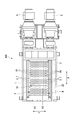
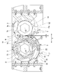
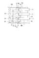
- FIG. 2 is a cross-sectional view taken along line X1-X1 in FIG. 1, showing a crusher. It is the figure which looked at the rotary blade of 1st embodiment of this invention, the spacer, and the screen from the axial direction of the rotating shaft. It is a top view of the screen of 1st embodiment of this invention. It is the figure which looked at the screen of 1st embodiment of this invention from the axial direction of the rotating shaft. It is a figure explaining the effect
- the crusher of 1st embodiment of this invention is demonstrated in detail with reference to drawings.
- the crusher of this embodiment is, for example, a biaxial shear crusher that crushes to-be-processed objects (waste) such as wood, bamboo, and garbage into a crushed material of a predetermined size (length, particle size) ( A multiaxial shearing crusher).
- the crusher of this embodiment is particularly suitable for crushing wood materials and bamboo materials that contain a large amount of long objects to be processed.
- the crusher 100 includes a casing 25, a pair of crushing mechanisms 4, a screen 20 that receives an object to be processed crushed by the crushing mechanism 4 and drops it downward. It is equipped with.
- the crushing mechanism 4 includes a pair of rotary shafts 1 and 2 arranged in parallel with each other inside the casing 25, and a plurality of rotary blades 3 attached to the rotary shafts 1 and 2 with an interval in the axial direction. And a plurality of spacers 10 attached between the rotary blades 3 adjacent to each other in the axial direction of the rotary shaft 1 and a drive device 5 such as an electric motor for rotating the rotary shafts 1 and 2.
- a drive device 5 such as an electric motor for rotating the rotary shafts 1 and 2.
- one rotating shaft 1 is referred to as a first rotating shaft 1
- the other rotating shaft is referred to as a second rotating shaft 2.
- the first rotating shaft 1 and the second rotating shaft 2 of the present embodiment are each driven by a driving device 5.
- the first rotating shaft 1 is set to rotate in the T1 direction in FIG. 3, and the second rotating shaft 2 is set to rotate in the T2 direction in FIG.
- the 1st rotating shaft 1 and the 2nd rotating shaft 2 can rotate not only in the T1 direction of FIG. 3, but the T2 direction, and a reverse direction. For example, when a large load is applied to the driving device 5 during crushing, it can be rotated in the reverse direction.
- the drive device 5 can arbitrarily set the rotation speed of the output shaft. That is, the first rotating shaft 1 and the second rotating shaft 2 can be rotated at a desired rotational speed. In the crusher 100 of the present embodiment, the first rotating shaft 1 is rotated at a low speed, and the second rotating shaft 2 is rotated at a higher speed than the first rotating shaft 1. That is, the rotation speed of the first rotation shaft 1 and the rotation speed of the second rotation shaft 2 are different, and the rotation speed of the first rotation shaft 1 is lower than the rotation speed of the second rotation shaft 2. It should be noted that, using one driving device 5 and a gear mechanism that transmits the driving force of the driving device 5 to the two rotating shafts 1 and 2, the two rotating shafts 1 and 2 are connected using one driving device 5. It may be configured to drive.
- the first rotating shaft 1 and the second rotating shaft 2 have a hexagonal cross-sectional shape as shown in FIG. 3, and are rotated around the axes O 1 and O 2 by the driving device 5.
- the cross-sectional shape of the 1st rotating shaft 1 and the 2nd rotating shaft 2 should just be a cross-sectional polygonal shape, for example, is good also as square shape.
- the rotary shafts 1 and 2 may have a circular cross section and may be fixed using the spacer 10 and the rotary blade 3 and a key.
- the scraper 21 is provided from the side wall of the casing 25 toward a position facing the rotary blade 3 and the spacer 10.
- the scraper 21 prevents the object to be processed from falling between the rotary blade 3 and the casing 25 or scrapes off the object to be processed sandwiched between the rotary blades 3.
- the scraper 21 is formed in a comb-teeth shape when viewed from above so as to allow passage of the rotary blade 3.
- the tip of the scraper 21 is formed in a semicircular arc shape so as to be close to the peripheral surfaces of the rotary blade 3 and the spacer 10.
- the axes O1 and O2 of the first rotating shaft 1 and the second rotating shaft 2 are parallel.
- the direction along the axes O1 and O2 is simply referred to as an axial direction A.
- a horizontal direction orthogonal to the axial direction A is referred to as a width direction Y of the rotary shafts 1 and 2.
- the width direction Y is an arrangement direction in which the rotation axes 1 and 2 are arranged.
- the rotary blades 3 and the spacers 10 are alternately arranged in the axial direction A.
- the width (thickness) in the axial direction A of the rotary blade 3 and the width in the axial direction A of the spacer 10 are the same.
- the rotary blades 3 and the spacers 10 attached to the first rotary shaft 1 and the rotary blades 3 and the spacers 10 attached to the second rotary shaft 2 are arranged so as to alternate in the axial direction A. .
- the rotary blade 3 attached to the first rotary shaft 1 and the spacer 10 attached to the second rotary shaft 2 adjacent to the first rotary shaft 1 have the same position in the axial direction A. It is arranged to be.
- a part of the rotation locus of the rotary blade 3 attached to the first rotary shaft 1 and a part of the rotation locus of the rotary blade 3 attached to the second rotary shaft 2 are overlapped when viewed from the axial direction A. ing.
- the crusher 100 shears and crushes the workpiece by rotating the rotary blade 3 around the axes O1 and O2 together with the rotary shafts 1 and 2 of each crushing mechanism 4.
- the rotary blade 3 is inserted into the polygonal center hole 3a with the rotary shafts 1 and 2 fitted therein, and is fixed to the rotary shafts 1 and 2 while being coaxially arranged on the rotary shafts 1 and 2.
- a crushing blade 7 which is detachably attached to the outer periphery of the blade receiving base 6 with a cutting blade portion 9 disposed radially outside the centers of the axes O1 and O2 and arranged in parallel in the circumferential direction of the centers of the axes O1 and O2. It is configured with.
- the trajectory drawn by the tip of the cutting edge portion 9 of the rotary blade 3 attached to the rotary shafts 1 and 2 is referred to as rotation trajectories L1 and L2.
- a semi-cylindrical screen 20 having a plurality of opening holes 22 through which the pulverized material crushed to a predetermined size is passed. . Only the crushed material that has been crushed to such a size as to pass through the opening hole 22 falls downward through the screen 20.
- the screen 20 receives the crushed material crushed by the crushing mechanism 4 outside the rotation locus L1 of the plurality of rotary blades 3 provided on the first rotary shaft 1.
- the screen 20 includes a curved surface portion 30 having a curved plate shape, a bracket portion 26 provided on one side in the width direction Y of the curved surface portion 30, and the other side in the width direction Y of the curved surface portion 30. And a plurality of extensions 24 provided in the.
- a side of the curved surface portion 30 opposite to the bracket portion 26 is supported by a predetermined support member 27.
- the curved surface portion 30 extends in the axial direction A and has a cross-sectional shape that forms an arc shape when viewed from the axial direction A.
- the curved curvature of the curved surface portion 30 is smaller than the curvature of the rotation locus L1.
- the center of curvature of the main surface 30 a of the curved surface portion 30 of the present embodiment substantially coincides with the central axis O ⁇ b> 1 of the first rotation shaft 1.
- a gap G is formed between the curved surface portion 30 and the rotation locus L1.
- the gap G is appropriately set depending on the size (length, desired size) of the desired crushed material.
- the dimension of the gap G can be set to about 1 ⁇ 2 of the size of the crushed material. Note that the gap G between the curved surface portion 30 and the rotation locus L1 does not have to be constant, and may gradually increase toward the outside in the width direction Y, for example.
- a plurality of opening holes 22 are formed in the curved surface portion 30.
- the plurality of opening holes 22 are regularly arranged in the curved surface portion 30.
- the arrangement of the plurality of opening holes 22 may be, for example, a staggered arrangement or a grid-like arrangement. Further, the arrangement of the plurality of opening holes 22 is not necessarily regular, and the number may be gradually reduced toward the end in the width direction Y.
- the opening hole 22 of this embodiment has a square shape.
- size of the opening hole 22 is suitably set with the size of the desired crushed material.
- the length of one side can be set to the same level as the size of the crushed material.
- the shape of the opening hole 22 is not limited to a square shape, and can be changed according to a crushed object such as a rectangular shape, a hexagonal shape, or a circular shape.
- the aperture ratio of the entire curved surface portion 30 can also be set as appropriate.
- the opening ratio of the curved surface portion 30 can be about 50%.
- a plurality of crushing protrusions 23 are formed on the curved surface portion 30.
- the crushing protrusion 23 has a pyramid shape having a sharp apex. That is, the plurality of crushing protrusions 23 have such a shape that the crushing matter staying on the screen 20 is cut by the crushing protrusions 23 when moving on the screen 20 as the rotary blade 3 rotates.
- the shape of the crushing protrusion 23 is not limited to this, and may be a knife shape (a plate shape having a sharp blade).
- the bracket portion 26 is a member that protrudes in the width direction Y from one side in the width direction Y of the curved surface portion 30, and is provided at a plurality of positions at intervals in the axial direction A.
- the bracket portion 26 is fixed to the scraper 21 using a fastening member such as a bolt 28.
- the bracket portion 26 (screen 20) may be fixed to the casing 25.
- the plurality of extending portions 24 are formed on the other side 30 b in the width direction Y of the curved surface portion 30 (end portions in the arrangement direction of the pair of rotating shafts 1 and 2).
- the other side 20a in the width direction Y of the screen 20 has a rectangular wave shape when viewed from above.
- the screen 20 has a shape along the rotation trajectory of the spacer 10 and the rotary blade 3 when viewed from above. That is, since the rotation locus of the spacer 10 and the rotary blade 3 viewed from above has a rectangular wave shape, the side 20a of the screen 20 also has a rectangular wave shape.
- the extension portion 24 is disposed on the inner peripheral side of the rotation locus L2 of the rotary blade 3 of the second rotary shaft 2.
- at least a part of the screen 20 is extended to the inner peripheral side of the rotation locus L2 of the rotary blade 3 of the second rotary shaft 2.
- the gap between the tip of the extension 24 and the spacer 10 is set to be as small as possible. That is, the screen 20 extends to the extent that it does not contact the outer peripheral surface 10 a of the spacer 10.
- the side 30b of the curved surface portion 30 is formed so as not to interfere with the rotation locus L2 of the rotary blade 3.
- the gap between the side 30b of the curved surface portion 30 and the rotation locus L2 is set to be as small as possible.
- the screen 20 is disposed only below the first rotating shaft 1, and no screen is disposed below the second rotating shaft 2.
- below the rotary blade 3 of the second rotary shaft 2 is a passage for crushed material without a screen.
- action of the crusher 100 of this embodiment is demonstrated.
- the first rotating shaft 1 is rotated in one direction (T1 direction) at a low speed
- the second rotating shaft 2 is rotated in another direction (T2 direction) at a high speed.
- T1 direction the first rotating shaft 1
- T2 direction another direction
- T2 direction another direction
- the workpiece B is introduced from the insertion port 19 that opens above the rotary shafts 1 and 2, the rotary blade 3 fitted to the first rotary shaft 1 and the rotary blade 3 fitted to the second rotary shaft 2.
- the workpiece B is sheared and crushed.
- the gap between the spacer 10 fitted to the first rotary shaft 1 and the rotary blade 3 fitted to the second rotary shaft 2, and the spacer 10 fitted to the second rotary shaft 2 and the first The workpieces enter the gaps H between the rotary blades 3 fitted to the rotary shaft 1, and the workpiece B is crushed by the rotary blades 3 at a size corresponding to the size of the gaps H. C falls downward.
- the crushed material C falls on the screen 20, is discharged through the opening hole 22 of the screen 20, or is discharged from the space S (see FIG. 4) between the extensions 24 adjacent in the axial direction. .
- the crushed material C crushed to a size that can pass through the opening hole is discharged through the opening hole 22.
- the object to be processed B which is a long object to be processed B, which has passed through between the spacer 10 and the rotary blade 3, and the object to be crushed to a size that can pass through the opening hole 22, are screened.
- Stay on top of 20 The processing object B and the crushed material C staying on the screen 20 are continuously crushed by the rotary blade 3 and the crushing protrusion 23.
- the crushed material C crushed to an appropriate size by the rotary blade 3 and the crushing protrusion 23 falls below the opening hole 22.
- the crushed material C is also discharged from the space S between the extension portions 24 adjacent to each other in the axial direction A. That is, among the crushed material C crushed by the pair of rotary blades 3, the crushed material C scraped by the rotary blade 3 of the second rotary shaft 2 falls below the space S instead of the opening hole 22. As described above, since no screen is installed below the second rotary shaft 2, the crushed material C scraped by the rotary blade 3 of the second rotary shaft 2 is quickly discharged.
- the first rotating shaft 1 rotates at a lower speed than the second rotating shaft 2.
- the crushed material C that does not need to pass through the screen is discharged without stagnation from the second rotating shaft 2 side, compared with the case where the screens are provided on both the rotating shafts 1 and 2.
- the processing efficiency of the workpiece B can be improved.
- no screen is installed on the second rotating shaft 2 side, the load applied to the second rotating shaft 2 by the crushed material C staying on the screen can be reduced.
- by retaining the long object to be processed passing through between the spacer 10 and the rotary blade 3 on the screen 20 it is possible to prevent the long object from slipping through.
- the screen 20 is provided below the first rotary shaft 1 that rotates at a lower speed than the second rotary shaft 2, surplus power of the first rotary shaft 1 that is not loaded compared to the second rotary shaft 2 is obtained. By using this, the crushed material C staying on the screen 20 can be crushed. That is, the driving force of the driving device 5 that drives the first rotating shaft 1 can be used more efficiently. Further, since the screen 20 is fixed using a fastening member such as a bolt 28, the screen 20 can be easily replaced.
- the rotational speed of the first rotary shaft 1 on the side where the screen 20 is provided is slower than the rotational speed of the second rotary shaft 2, but the present invention is not limited to this, and the side on which the screen 20 is provided.
- the rotation speed of the first rotation shaft 1 may be faster than the rotation speed of the second rotation shaft 2.
- the screen 20 may be installed below the rotation axis on the high speed side. By installing the screen 20 below the rotary shaft on the high speed side, the crushing efficiency may be improved because the crushing by the crushing protrusions 23 of the rotary blade 3 and the screen 20 is performed faster.
- the spacer 10 ⁇ / b> B of the present embodiment includes a bearing 32 that is coaxially attached to the rotary shaft 2, and a cylindrical shape that is coaxially attached to the rotary shaft 2 on the outer peripheral surface of the bearing 32.
- the spacer main body 34 is provided.
- a second spacer 33 is interposed between the bearing 32 and the rotating shaft 2 having a hexagonal cross section.
- the outer peripheral surface of the rotating shaft 2 where the bearing 32 is attached can be made cylindrical by matching the bearing 32. Good. That is, the spacer 10 ⁇ / b> B of the present embodiment is attached to the rotating shaft 2 so as to be rotatable.
- the extension portion 24B of the screen 20B of the present embodiment is connected to the spacer main body 34 (spacer 10B) at the connection portion 24a. That is, there is no radial gap between the spacer 10B of this embodiment and the extension 24B of the screen 20B.
- the other side in the width direction Y of the screen 20B can be firmly fixed. That is, the extension 24B can be prevented from being deformed and coming into contact with the rotary blade 3.
- the embodiment of the present invention has been described in detail above, but various modifications can be made without departing from the technical idea of the present invention.
- the rotational speeds of the pair of rotating shafts 1 and 2 are different, but the rotating speeds of the rotating shafts 1 and 2 may be the same.
- the rotary blade 3 shall have the some crushing blade 7 divided
Abstract
Provided is a crushing machine that comprises: a pair of rotary shafts 1, 2 disposed parallel to each other; a plurality of rotary blades 3 attached, with intervals therebetween, to each of the rotary shafts 1, 2 in the axial direction, where rotary blades 3 attached to one rotary shaft 1 and rotary blades 3 attached to the other rotary shaft 2 are attached so that the rotation trajectories L1, L2 partially overlap as viewed from the axial direction of the rotary shafts; and a screen 20 which receives crushed material on the outside of the rotation trajectory L1 of the plurality of rotary blades 3 attached to the one rotary shaft 1 and which allows the crushed material of a prescribed size or less to fall. At least part of the end section of the screen 20 in the array direction of the pair of rotary shafts 1, 2 is disposed to the inner peripheral side from the rotation trajectory L2 of the rotary blades 3 attached to the other rotary shaft 2.
Description
本発明は、木材、ごみ等の被処理物を破砕する破砕機に関する。
本願は、2015年7月15日に出願された特願2015-141390号について優先権を主張し、その内容をここに援用する。 The present invention relates to a crusher that crushes objects to be processed such as wood and garbage.
This application claims priority in Japanese Patent Application No. 2015-141390 for which it applied on July 15, 2015, and uses the content here.
従来、木材(例えばバイオマス発電用木質材)、竹材、可燃・不燃性ごみ等の被処理物を破砕処理する手段として破砕機が用いられている。破砕機としては、回転式破砕機、せん断式破砕機、二軸せん断式破砕機等が知られている。いずれの破砕機も回転軸に取り付けられて周方向に複数の破砕刃が形成された回転刃を有している。
Conventionally, a crusher has been used as a means for crushing to-be-processed objects such as wood (for example, wood for biomass power generation), bamboo, and combustible / noncombustible waste. As crushers, rotary crushers, shear crushers, biaxial shear crushers, and the like are known. Each crusher has a rotary blade that is attached to a rotating shaft and has a plurality of crushing blades formed in the circumferential direction.
また、被処理物を破砕することによって生成される破砕物を所定のサイズ(粒度)にするために、回転刃の下方にスクリーンを設けた破砕機も知られている(例えば、特許文献1参照)。スクリーンには、規則的に形成された複数の開口孔が形成されており、破砕物は、開口孔を通過できるサイズまでスクリーン上を通過する回転刃によって破砕され続ける。
In addition, a crusher is also known in which a screen is provided below a rotary blade in order to make a crushed material generated by crushing an object to be processed into a predetermined size (particle size) (see, for example, Patent Document 1). ). A plurality of regularly formed opening holes are formed in the screen, and the crushed material continues to be crushed by a rotary blade passing on the screen to a size that can pass through the opening holes.
スクリーンを備えた破砕機の場合、破砕物のサイズを一定以下に揃えることが可能になる。しかしながら、スクリーンを備えた破砕機の場合、破砕物が排出される開口孔の数に限界がある。よって、破砕物のスクリーン上の滞留が増えてスクリーンが無い場合と比較して破砕処理量が減少するという課題がある。また、スクリーン上に滞留する破砕物は、摩擦抵抗となるため、回転軸の負荷となり、破砕能力の低下に繋がるという課題がある。
In the case of a crusher equipped with a screen, it becomes possible to make the size of the crushed material below a certain level. However, in the case of a crusher equipped with a screen, there is a limit to the number of opening holes through which crushed material is discharged. Therefore, there exists a subject that the amount of crushing processes reduces compared with the case where the residence of the crushing material on the screen increases and there is no screen. Moreover, since the crushed material staying on the screen becomes a frictional resistance, there is a problem that it becomes a load on the rotating shaft and leads to a decrease in the crushing capacity.
この発明は、被処理物の処理効率を向上させると共に、回転軸への負荷を低減することができる破砕機を提供することを目的とする。
An object of the present invention is to provide a crusher capable of improving the processing efficiency of a workpiece and reducing the load on a rotating shaft.
本発明の第一の態様によれば、破砕機は、互いに平行に配置された一対の回転軸と、各々の前記回転軸に軸方向に間隔をあけて取り付けられた複数の回転刃であって、一方の前記回転軸に取り付けられた回転刃と他方の前記回転軸に取り付けられた回転刃とが、前記回転軸の軸方向から見て回転軌跡を一部重ねて取り付けられた複数の回転刃と、一方の前記回転軸に取り付けられた複数の前記回転刃の回転軌跡の外側で破砕物を受けて所定の大きさ以下の破砕物を落下させるスクリーンと、を備え、前記スクリーンの前記一対の回転軸の配列方向の端部の少なくとも一部は、他方の前記回転軸に取り付けられた前記回転刃の回転軌跡よりも内周側に配置されていることを特徴とする。
According to the first aspect of the present invention, the crusher is a pair of rotary shafts arranged in parallel to each other, and a plurality of rotary blades attached to each of the rotary shafts with an interval in the axial direction. A plurality of rotary blades, wherein a rotary blade attached to one of the rotary shafts and a rotary blade attached to the other of the rotary shafts are attached so as to partially overlap the rotation locus when viewed from the axial direction of the rotary shaft And a screen that receives the crushed material outside the rotation trajectory of the plurality of rotary blades attached to one of the rotating shafts and drops the crushed material having a predetermined size or less, and the pair of the screens At least a part of the end portion in the arrangement direction of the rotation shafts is arranged on the inner peripheral side with respect to the rotation locus of the rotation blade attached to the other rotation shaft.
このような構成によれば、他方の回転軸側からは、スクリーンを通す必要のない破砕物が滞りなく破砕物が排出されるため、両方の回転軸にスクリーンを設ける場合と比較して、被処理物の処理効率を向上させることができる。また、他方の回転軸側には、スクリーンが設置されないため、スクリーンに滞留する破砕物によって他方の回転軸にかかる負荷を低減することができる。
また、回転刃の間をすり抜けた長尺状の被処理物をスクリーン上に滞留させることにより、長尺状の被処理物のすり抜けを防止することができる。 According to such a configuration, since the crushed material that does not need to pass through the screen is discharged from the other rotating shaft side without stagnation, the crushed material is discharged compared to the case where the screens are provided on both rotating shafts. The processing efficiency of the processed product can be improved. Moreover, since the screen is not installed on the other rotating shaft side, the load applied to the other rotating shaft by the crushed material staying on the screen can be reduced.
Further, by retaining the long object to be processed that has passed between the rotary blades on the screen, it is possible to prevent the long object to pass through.
上記破砕機において、前記回転軸に前記回転刃と軸方向に交互に取り付けられている複数のスペーサを備え、前記スクリーンは、前記スペーサの外周面まで延びていてよい。
The crusher may include a plurality of spacers attached to the rotary shaft alternately in the axial direction with the rotary blade, and the screen may extend to an outer peripheral surface of the spacer.
上記破砕機において、一方の前記回転軸の回転速度は、他方の前記回転軸の回転速度より低くしてよい。
In the crusher, the rotation speed of one of the rotation shafts may be lower than the rotation speed of the other rotation shaft.
このような構成によれば、より負荷の少ない回転軸の余剰動力を、回転刃とスクリーンとを用いた破砕に用いることができる。
According to such a configuration, surplus power of the rotating shaft with less load can be used for crushing using the rotary blade and the screen.
本発明によれば、他方の回転軸側からは、スクリーンを通す必要のない破砕物が滞りなく破砕物が排出されるため、両方の回転軸にスクリーンを設ける場合と比較して、被処理物の処理効率を向上させることができる。また、他方の回転軸側には、スクリーンが設置されないため、スクリーンに滞留する破砕物によって他方の回転軸にかかる負荷を低減することができる。
According to the present invention, since the crushed material that does not need to pass through the screen is discharged without delay from the other rotating shaft side, the object to be processed is compared with the case where screens are provided on both rotating shafts. The processing efficiency can be improved. Moreover, since the screen is not installed on the other rotating shaft side, the load applied to the other rotating shaft by the crushed material staying on the screen can be reduced.
(第一実施形態)
以下、本発明の第一実施形態の破砕機について図面を参照して詳細に説明する。
本実施形態の破砕機は、例えば木質材、竹材、ごみ等の被処理物(廃棄物)を破砕して、所定のサイズ(長さ、粒度)の破砕物にする二軸せん断式破砕機(多軸せん断式破砕機)である。本実施形態の破砕機は、特に、長尺状の被処理物を多く含む木質材、竹材の破砕に最適である。 (First embodiment)
Hereinafter, the crusher of 1st embodiment of this invention is demonstrated in detail with reference to drawings.
The crusher of this embodiment is, for example, a biaxial shear crusher that crushes to-be-processed objects (waste) such as wood, bamboo, and garbage into a crushed material of a predetermined size (length, particle size) ( A multiaxial shearing crusher). The crusher of this embodiment is particularly suitable for crushing wood materials and bamboo materials that contain a large amount of long objects to be processed.
図1、図2、及び図3に示すように、破砕機100は、ケーシング25と、一対の破砕機構4と、破砕機構4によって破砕された被処理物を受けるとともに下方に落下させるスクリーン20と、を備えている。
破砕機構4は、ケーシング25の内部に互いに平行に配置された一対の回転軸1,2と、各々の回転軸1,2に軸方向に間隔をあけて取り付けられている複数の回転刃3と、回転軸1の軸方向に隣り合う回転刃3同士の間に取り付けられている複数のスペーサ10と、回転軸1,2を回転駆動させる電動機などの駆動装置5と、を有している。以下、一方の回転軸1を第一回転軸1、他方の回転軸を第二回転軸2と呼ぶ。 As shown in FIGS. 1, 2, and 3, thecrusher 100 includes a casing 25, a pair of crushing mechanisms 4, a screen 20 that receives an object to be processed crushed by the crushing mechanism 4 and drops it downward. It is equipped with.
Thecrushing mechanism 4 includes a pair of rotary shafts 1 and 2 arranged in parallel with each other inside the casing 25, and a plurality of rotary blades 3 attached to the rotary shafts 1 and 2 with an interval in the axial direction. And a plurality of spacers 10 attached between the rotary blades 3 adjacent to each other in the axial direction of the rotary shaft 1 and a drive device 5 such as an electric motor for rotating the rotary shafts 1 and 2. Hereinafter, one rotating shaft 1 is referred to as a first rotating shaft 1, and the other rotating shaft is referred to as a second rotating shaft 2.
破砕機構4は、ケーシング25の内部に互いに平行に配置された一対の回転軸1,2と、各々の回転軸1,2に軸方向に間隔をあけて取り付けられている複数の回転刃3と、回転軸1の軸方向に隣り合う回転刃3同士の間に取り付けられている複数のスペーサ10と、回転軸1,2を回転駆動させる電動機などの駆動装置5と、を有している。以下、一方の回転軸1を第一回転軸1、他方の回転軸を第二回転軸2と呼ぶ。 As shown in FIGS. 1, 2, and 3, the
The
本実施形態の第一回転軸1及び第二回転軸2は、それぞれが駆動装置5によって駆動されている。第一回転軸1は、図3のT1方向、第二回転軸2は、図3のT2方向に回転するように設定されている。なお、第一回転軸1及び第二回転軸2は図3のT1方向、T2方向に限らず、逆方向にも回転可能である。例えば、破砕中において駆動装置5に大きな負荷がかかった場合等、逆方向に回転させることができる。
The first rotating shaft 1 and the second rotating shaft 2 of the present embodiment are each driven by a driving device 5. The first rotating shaft 1 is set to rotate in the T1 direction in FIG. 3, and the second rotating shaft 2 is set to rotate in the T2 direction in FIG. In addition, the 1st rotating shaft 1 and the 2nd rotating shaft 2 can rotate not only in the T1 direction of FIG. 3, but the T2 direction, and a reverse direction. For example, when a large load is applied to the driving device 5 during crushing, it can be rotated in the reverse direction.
駆動装置5は出力軸の回転数を任意に設定可能である。即ち、第一回転軸1及び第二回転軸2を所望の回転数で回転させることができる。本実施形態の破砕機100においては、第一回転軸1を低速で回転させ、第二回転軸2を第一回転軸1よりも高速で回転させている。即ち、第一回転軸1の回転速度と第二回転軸2の回転速度は異なり、第一回転軸1の回転速度は、第二回転軸2の回転速度よりも低い。
なお、一つの駆動装置5と、この駆動装置5の駆動力を二つの回転軸1、2に伝達する歯車機構とを用いて、一つの駆動装置5を用いて二つの回転軸1、2を駆動する構成としてもよい。 Thedrive device 5 can arbitrarily set the rotation speed of the output shaft. That is, the first rotating shaft 1 and the second rotating shaft 2 can be rotated at a desired rotational speed. In the crusher 100 of the present embodiment, the first rotating shaft 1 is rotated at a low speed, and the second rotating shaft 2 is rotated at a higher speed than the first rotating shaft 1. That is, the rotation speed of the first rotation shaft 1 and the rotation speed of the second rotation shaft 2 are different, and the rotation speed of the first rotation shaft 1 is lower than the rotation speed of the second rotation shaft 2.
It should be noted that, using onedriving device 5 and a gear mechanism that transmits the driving force of the driving device 5 to the two rotating shafts 1 and 2, the two rotating shafts 1 and 2 are connected using one driving device 5. It may be configured to drive.
なお、一つの駆動装置5と、この駆動装置5の駆動力を二つの回転軸1、2に伝達する歯車機構とを用いて、一つの駆動装置5を用いて二つの回転軸1、2を駆動する構成としてもよい。 The
It should be noted that, using one
第一回転軸1及び第二回転軸2は、図3に示すように、六角形の断面形状であり、駆動装置5によって軸線O1、O2周りに回転する。なお、第一回転軸1及び第二回転軸2の断面形状は、断面多角形状であれば良く、例えば、四角形状としてもよい。また、回転軸1、2を断面円形とし、スペーサ10及び回転刃3とキーを用いて固定してもよい。
The first rotating shaft 1 and the second rotating shaft 2 have a hexagonal cross-sectional shape as shown in FIG. 3, and are rotated around the axes O 1 and O 2 by the driving device 5. In addition, the cross-sectional shape of the 1st rotating shaft 1 and the 2nd rotating shaft 2 should just be a cross-sectional polygonal shape, for example, is good also as square shape. Alternatively, the rotary shafts 1 and 2 may have a circular cross section and may be fixed using the spacer 10 and the rotary blade 3 and a key.
ケーシング25の側壁からは、回転刃3及びスペーサ10に対向する位置に向けてスクレーパ21が設けられている。スクレーパ21は、被処理物が回転刃3とケーシング25との間に落下するのを防止したり、回転刃3に挟まった被処理物をかき取ったりする。スクレーパ21は、回転刃3の通過を許容するように、上方から見て櫛歯状に形成されている。スクレーパ21の先端部は、回転刃3及びスペーサ10の周面に近接するよう半円弧状に形成されている。
The scraper 21 is provided from the side wall of the casing 25 toward a position facing the rotary blade 3 and the spacer 10. The scraper 21 prevents the object to be processed from falling between the rotary blade 3 and the casing 25 or scrapes off the object to be processed sandwiched between the rotary blades 3. The scraper 21 is formed in a comb-teeth shape when viewed from above so as to allow passage of the rotary blade 3. The tip of the scraper 21 is formed in a semicircular arc shape so as to be close to the peripheral surfaces of the rotary blade 3 and the spacer 10.
第一回転軸1及び第二回転軸2の軸線O1、O2は平行である。以下、軸線O1、O2に沿う方向を単に軸方向Aと呼ぶ。また、軸方向Aに直交する水平方向を回転軸1,2の幅方向Yと呼ぶ。幅方向Yは、回転軸1、2が配列される方向である配列方向である。
各々の破砕機構4において、回転刃3とスペーサ10とは、軸方向Aに交互に配置されている。回転刃3の軸方向Aの幅(厚さ)と、スペーサ10の軸方向Aの幅とは、同一である。 The axes O1 and O2 of the first rotatingshaft 1 and the second rotating shaft 2 are parallel. Hereinafter, the direction along the axes O1 and O2 is simply referred to as an axial direction A. A horizontal direction orthogonal to the axial direction A is referred to as a width direction Y of the rotary shafts 1 and 2. The width direction Y is an arrangement direction in which the rotation axes 1 and 2 are arranged.
In each crushingmechanism 4, the rotary blades 3 and the spacers 10 are alternately arranged in the axial direction A. The width (thickness) in the axial direction A of the rotary blade 3 and the width in the axial direction A of the spacer 10 are the same.
各々の破砕機構4において、回転刃3とスペーサ10とは、軸方向Aに交互に配置されている。回転刃3の軸方向Aの幅(厚さ)と、スペーサ10の軸方向Aの幅とは、同一である。 The axes O1 and O2 of the first rotating
In each crushing
第一回転軸1に取り付けられている回転刃3及びスペーサ10と、第二回転軸2に取り付けられている回転刃3及びスペーサ10とは、軸方向Aに互い違いとなるように配置されている。換言すれば、第一回転軸1に取り付けられている回転刃3と、第一回転軸1と隣り合う第二回転軸2に取り付けられているスペーサ10とは、軸方向Aの位置が同じとなるように配置されている。
The rotary blades 3 and the spacers 10 attached to the first rotary shaft 1 and the rotary blades 3 and the spacers 10 attached to the second rotary shaft 2 are arranged so as to alternate in the axial direction A. . In other words, the rotary blade 3 attached to the first rotary shaft 1 and the spacer 10 attached to the second rotary shaft 2 adjacent to the first rotary shaft 1 have the same position in the axial direction A. It is arranged to be.
第一回転軸1に取り付けられている回転刃3の回転軌跡の一部と、第二回転軸2に取り付けられている回転刃3の回転軌跡の一部とは、軸方向Aから見て重なっている。破砕機100は、各々の破砕機構4の回転軸1、2とともに回転刃3を軸線O1、O2周りに回転させることによって被処理物をせん断破砕する。
A part of the rotation locus of the rotary blade 3 attached to the first rotary shaft 1 and a part of the rotation locus of the rotary blade 3 attached to the second rotary shaft 2 are overlapped when viewed from the axial direction A. ing. The crusher 100 shears and crushes the workpiece by rotating the rotary blade 3 around the axes O1 and O2 together with the rotary shafts 1 and 2 of each crushing mechanism 4.
回転刃3は、回転軸1、2を多角形状の中心孔3aに挿通して嵌着され、回転軸1、2に互いの軸線を同軸上に配した状態で固着される刃受台6と、軸線O1、O2中心の径方向外側に切刃部9を配して刃受台6の外周に着脱可能に取り付けられ、軸線O1、O2中心の周方向に複数並設される破砕刃7とを備えて構成されている。以下、回転軸1、2に取り付けられている回転刃3の切刃部9の先端が描く軌跡を回転軌跡L1、L2と呼ぶ。
The rotary blade 3 is inserted into the polygonal center hole 3a with the rotary shafts 1 and 2 fitted therein, and is fixed to the rotary shafts 1 and 2 while being coaxially arranged on the rotary shafts 1 and 2. A crushing blade 7 which is detachably attached to the outer periphery of the blade receiving base 6 with a cutting blade portion 9 disposed radially outside the centers of the axes O1 and O2 and arranged in parallel in the circumferential direction of the centers of the axes O1 and O2. It is configured with. Hereinafter, the trajectory drawn by the tip of the cutting edge portion 9 of the rotary blade 3 attached to the rotary shafts 1 and 2 is referred to as rotation trajectories L1 and L2.
第一回転軸1の下方(回転刃3の下方)には、所定のサイズまで破砕された粉砕物を通すための複数の開口孔22が形成された半円筒形状のスクリーン20が取り付けられている。開口孔22を通るほどの大きさまで破砕された破砕物のみが、スクリーン20を介して下方に落下する。
Below the first rotary shaft 1 (below the rotary blade 3) is attached a semi-cylindrical screen 20 having a plurality of opening holes 22 through which the pulverized material crushed to a predetermined size is passed. . Only the crushed material that has been crushed to such a size as to pass through the opening hole 22 falls downward through the screen 20.
スクリーン20は、第一回転軸1に設けられている複数の回転刃3の回転軌跡L1の外側で、破砕機構4によって破砕された破砕物を受ける。スクリーン20は、湾曲した板形状をなしている湾曲面部30と、湾曲面部30の幅方向Yの一方の側辺に設けられたブラケット部26と、湾曲面部30の幅方向Yの他方の側辺に設けられた複数の延長部24と、を有している。
湾曲面部30におけるブラケット部26とは反対の側は、所定の支持部材27によって支持されている。 Thescreen 20 receives the crushed material crushed by the crushing mechanism 4 outside the rotation locus L1 of the plurality of rotary blades 3 provided on the first rotary shaft 1. The screen 20 includes a curved surface portion 30 having a curved plate shape, a bracket portion 26 provided on one side in the width direction Y of the curved surface portion 30, and the other side in the width direction Y of the curved surface portion 30. And a plurality of extensions 24 provided in the.
A side of thecurved surface portion 30 opposite to the bracket portion 26 is supported by a predetermined support member 27.
湾曲面部30におけるブラケット部26とは反対の側は、所定の支持部材27によって支持されている。 The
A side of the
湾曲面部30は、軸方向Aに延在しており、軸方向Aから見て円弧状をなす断面形状を有している。湾曲面部30の湾曲曲率は、回転軌跡L1の曲率より小さく形成されている。本実施形態の湾曲面部30の主面30aの曲率中心は、第一回転軸1の中心軸O1に略一致している。
The curved surface portion 30 extends in the axial direction A and has a cross-sectional shape that forms an arc shape when viewed from the axial direction A. The curved curvature of the curved surface portion 30 is smaller than the curvature of the rotation locus L1. The center of curvature of the main surface 30 a of the curved surface portion 30 of the present embodiment substantially coincides with the central axis O <b> 1 of the first rotation shaft 1.
湾曲面部30と回転軌跡L1との間には、隙間Gが形成されている。隙間Gは、所望の破砕物のサイズ(長さ、希望する大きさ)によって適宜設定される。例えば、隙間Gの寸法は、破砕物のサイズの1/2程度に設定することができる。なお、湾曲面部30と回転軌跡L1との間の隙間Gは一定である必要はなく、例えば、幅方向Yの外側に向かうに従って漸次広がっていてもよい。
A gap G is formed between the curved surface portion 30 and the rotation locus L1. The gap G is appropriately set depending on the size (length, desired size) of the desired crushed material. For example, the dimension of the gap G can be set to about ½ of the size of the crushed material. Note that the gap G between the curved surface portion 30 and the rotation locus L1 does not have to be constant, and may gradually increase toward the outside in the width direction Y, for example.
図4に示すように、湾曲面部30には、複数の開口孔22が形成されている。複数の開口孔22は、湾曲面部30に規則的に配置されている。複数の開口孔22の配置は、例えば、千鳥配列としてもよいし、碁盤目状配列としてもよい。また、複数の開口孔22の配置は、必ずしも規則的でなくてよく、幅方向Yの端部に向かうに従って、徐々に数を減らしてもよい。
As shown in FIG. 4, a plurality of opening holes 22 are formed in the curved surface portion 30. The plurality of opening holes 22 are regularly arranged in the curved surface portion 30. The arrangement of the plurality of opening holes 22 may be, for example, a staggered arrangement or a grid-like arrangement. Further, the arrangement of the plurality of opening holes 22 is not necessarily regular, and the number may be gradually reduced toward the end in the width direction Y.
本実施形態の開口孔22は、正方形状をなしている。開口孔22の大きさは、所望の破砕物のサイズによって適宜設定される。例えば、一辺の長さを破砕物のサイズと同程度に設定することができる。開口孔22の形状は、正方形状に限ることはなく、長方形状、六角形状、円形など破砕物に合わせて変更することができる。また、湾曲面部30全体の開口率も適宜設定することができる。例えば、湾曲面部30の開口率は50%程度とすることができる。
The opening hole 22 of this embodiment has a square shape. The magnitude | size of the opening hole 22 is suitably set with the size of the desired crushed material. For example, the length of one side can be set to the same level as the size of the crushed material. The shape of the opening hole 22 is not limited to a square shape, and can be changed according to a crushed object such as a rectangular shape, a hexagonal shape, or a circular shape. Moreover, the aperture ratio of the entire curved surface portion 30 can also be set as appropriate. For example, the opening ratio of the curved surface portion 30 can be about 50%.
図5に示すように、湾曲面部30には、複数の破砕突起23が形成されている。破砕突起23は、鋭利な頂部を有する角錐形状をなしている。即ち、複数の破砕突起23は、スクリーン20上に滞留する破砕物が回転刃3の回転に伴いスクリーン20上を移動する際に、破砕突起23によって切削されるような形状を有している。破砕突起23の形状はこれに限ることはなく、ナイフ状(鋭利な刃を有する板状)としてもよい。
As shown in FIG. 5, a plurality of crushing protrusions 23 are formed on the curved surface portion 30. The crushing protrusion 23 has a pyramid shape having a sharp apex. That is, the plurality of crushing protrusions 23 have such a shape that the crushing matter staying on the screen 20 is cut by the crushing protrusions 23 when moving on the screen 20 as the rotary blade 3 rotates. The shape of the crushing protrusion 23 is not limited to this, and may be a knife shape (a plate shape having a sharp blade).
ブラケット部26は、湾曲面部30の幅方向Yの一方の側辺から幅方向Yに突出する部材であり、軸方向Aに間隔をあけて複数個所に設けられている。ブラケット部26は、ボルト28等の締結部材を用いてスクレーパ21に固定されている。なお、ブラケット部26(スクリーン20)をケーシング25に固定してもよい。
The bracket portion 26 is a member that protrudes in the width direction Y from one side in the width direction Y of the curved surface portion 30, and is provided at a plurality of positions at intervals in the axial direction A. The bracket portion 26 is fixed to the scraper 21 using a fastening member such as a bolt 28. The bracket portion 26 (screen 20) may be fixed to the casing 25.
図4及び図5に示すように、複数の延長部24は、湾曲面部30の幅方向Yの他方の側辺30b(一対の回転軸1、2の配列方向の端部)に形成されており、これにより、スクリーン20の幅方向Yの他方の側辺20aは、上方から見て矩形波状をなしている。換言すれば、スクリーン20は、上方から見てスペーサ10と回転刃3の回転軌跡に沿う形状をなしている。即ち、上方から見たスペーサ10と回転刃3の回転軌跡が矩形波状をなしているため、スクリーン20の側辺20aも矩形波状をなしている。
As shown in FIGS. 4 and 5, the plurality of extending portions 24 are formed on the other side 30 b in the width direction Y of the curved surface portion 30 (end portions in the arrangement direction of the pair of rotating shafts 1 and 2). Thus, the other side 20a in the width direction Y of the screen 20 has a rectangular wave shape when viewed from above. In other words, the screen 20 has a shape along the rotation trajectory of the spacer 10 and the rotary blade 3 when viewed from above. That is, since the rotation locus of the spacer 10 and the rotary blade 3 viewed from above has a rectangular wave shape, the side 20a of the screen 20 also has a rectangular wave shape.
延長部24は、第二回転軸2の回転刃3の回転軌跡L2の内周側に配置されている。換言すれば、スクリーン20の少なくとも一部は、第二回転軸2の回転刃3の回転軌跡L2の内周側まで延長されている。延長部24の先端とスペーサ10との間の隙間は、可能な限り小さくなるように設定されている。即ち、スクリーン20は、スペーサ10の外周面10aに接触しない程度まで延びている。
湾曲面部30の側辺30bは、回転刃3の回転軌跡L2と干渉しないように形成されている。湾曲面部30の側辺30bと回転軌跡L2との間の隙間は、可能な限り小さくなるように設定されている。 Theextension portion 24 is disposed on the inner peripheral side of the rotation locus L2 of the rotary blade 3 of the second rotary shaft 2. In other words, at least a part of the screen 20 is extended to the inner peripheral side of the rotation locus L2 of the rotary blade 3 of the second rotary shaft 2. The gap between the tip of the extension 24 and the spacer 10 is set to be as small as possible. That is, the screen 20 extends to the extent that it does not contact the outer peripheral surface 10 a of the spacer 10.
Theside 30b of the curved surface portion 30 is formed so as not to interfere with the rotation locus L2 of the rotary blade 3. The gap between the side 30b of the curved surface portion 30 and the rotation locus L2 is set to be as small as possible.
湾曲面部30の側辺30bは、回転刃3の回転軌跡L2と干渉しないように形成されている。湾曲面部30の側辺30bと回転軌跡L2との間の隙間は、可能な限り小さくなるように設定されている。 The
The
本実施形態の破砕機100においては、スクリーン20は、第一回転軸1の下方のみに配置されており、第二回転軸2の下方にはスクリーンは配置されていない。即ち、第二回転軸2の回転刃3の下方は、スクリーンの存在しない、破砕物の通路となっている。
In the crusher 100 of the present embodiment, the screen 20 is disposed only below the first rotating shaft 1, and no screen is disposed below the second rotating shaft 2. In other words, below the rotary blade 3 of the second rotary shaft 2 is a passage for crushed material without a screen.
次に、本実施形態の破砕機100の作用について説明する。
本実施形態の破砕機100においては、図6に示すように、第一回転軸1を低速で一方向(T1方向)に、第二回転軸2を高速で他方向(T2方向)に回転させている。これら回転軸1、2の上方に開口する投入口19から被処理物Bを投入すると、第一回転軸1に嵌着された回転刃3と第二回転軸2に嵌着された回転刃3によって被処理物Bがせん断破砕される。 Next, the effect | action of thecrusher 100 of this embodiment is demonstrated.
In thecrusher 100 of this embodiment, as shown in FIG. 6, the first rotating shaft 1 is rotated in one direction (T1 direction) at a low speed, and the second rotating shaft 2 is rotated in another direction (T2 direction) at a high speed. ing. When the workpiece B is introduced from the insertion port 19 that opens above the rotary shafts 1 and 2, the rotary blade 3 fitted to the first rotary shaft 1 and the rotary blade 3 fitted to the second rotary shaft 2. Thus, the workpiece B is sheared and crushed.
本実施形態の破砕機100においては、図6に示すように、第一回転軸1を低速で一方向(T1方向)に、第二回転軸2を高速で他方向(T2方向)に回転させている。これら回転軸1、2の上方に開口する投入口19から被処理物Bを投入すると、第一回転軸1に嵌着された回転刃3と第二回転軸2に嵌着された回転刃3によって被処理物Bがせん断破砕される。 Next, the effect | action of the
In the
また、第一回転軸1に嵌着されたスペーサ10と第二回転軸2に嵌着された回転刃3の間の隙間、及びに第二回転軸2に嵌着されたスペーサ10と第一回転軸1に嵌着された回転刃3の間の隙間Hにそれぞれ被処理物が入り込むとともに、回転刃3によってこの被処理物Bが隙間Hの大きさに応じたサイズで破砕され、破砕物Cとして下方に落下する。
Further, the gap between the spacer 10 fitted to the first rotary shaft 1 and the rotary blade 3 fitted to the second rotary shaft 2, and the spacer 10 fitted to the second rotary shaft 2 and the first The workpieces enter the gaps H between the rotary blades 3 fitted to the rotary shaft 1, and the workpiece B is crushed by the rotary blades 3 at a size corresponding to the size of the gaps H. C falls downward.
破砕物Cは、スクリーン20上に落下するか、スクリーン20の開口孔22を介して排出されるか、軸方向に隣り合う延長部24同士の間の空間S(図4参照)から排出される。
スクリーン20上に落下した破砕物Cのうち、開口孔を通過可能なサイズにまで破砕された破砕物Cは、開口孔22を介して排出される。 The crushed material C falls on thescreen 20, is discharged through the opening hole 22 of the screen 20, or is discharged from the space S (see FIG. 4) between the extensions 24 adjacent in the axial direction. .
Of the crushed material C falling on thescreen 20, the crushed material C crushed to a size that can pass through the opening hole is discharged through the opening hole 22.
スクリーン20上に落下した破砕物Cのうち、開口孔を通過可能なサイズにまで破砕された破砕物Cは、開口孔22を介して排出される。 The crushed material C falls on the
Of the crushed material C falling on the
一方、長尺状の被処理物Bであり、スペーサ10と回転刃3との間をすり抜けた被処理物Bや、開口孔22を通過可能なサイズまで破砕されなかった破砕物Cは、スクリーン20上に滞留する。スクリーン20上に滞留した被処理物B、破砕物Cは、回転刃3及び破砕突起23によって、引き続き破砕される。回転刃3及び破砕突起23によって、適当なサイズまで破砕された破砕物Cは、開口孔22より下方に落下する。
On the other hand, the object to be processed B, which is a long object to be processed B, which has passed through between the spacer 10 and the rotary blade 3, and the object to be crushed to a size that can pass through the opening hole 22, are screened. Stay on top of 20. The processing object B and the crushed material C staying on the screen 20 are continuously crushed by the rotary blade 3 and the crushing protrusion 23. The crushed material C crushed to an appropriate size by the rotary blade 3 and the crushing protrusion 23 falls below the opening hole 22.
また、軸方向Aに隣り合う延長部24同士の間の空間Sからも破砕物Cが排出される。即ち、一対の回転刃3によって破砕された破砕物Cのうち、第二回転軸2の回転刃3によって掻き出される破砕物Cは、開口孔22ではなく、空間Sより下方に落下する。
上述したように、第二回転軸2の下方には、スクリーンが設置されていないため、第二回転軸2の回転刃3によって掻き出される破砕物Cは、速やかに排出される。 Further, the crushed material C is also discharged from the space S between theextension portions 24 adjacent to each other in the axial direction A. That is, among the crushed material C crushed by the pair of rotary blades 3, the crushed material C scraped by the rotary blade 3 of the second rotary shaft 2 falls below the space S instead of the opening hole 22.
As described above, since no screen is installed below the secondrotary shaft 2, the crushed material C scraped by the rotary blade 3 of the second rotary shaft 2 is quickly discharged.
上述したように、第二回転軸2の下方には、スクリーンが設置されていないため、第二回転軸2の回転刃3によって掻き出される破砕物Cは、速やかに排出される。 Further, the crushed material C is also discharged from the space S between the
As described above, since no screen is installed below the second
また、本実施形態の破砕機100においては、第一回転軸1が第二回転軸2よりも低速で回転する。これにより、回転軸1、2が同じ回転数で回転する場合と比較して、被処理物によりせん断力がかけられるため、被処理物の破砕効率が高い。
Further, in the crusher 100 of the present embodiment, the first rotating shaft 1 rotates at a lower speed than the second rotating shaft 2. Thereby, compared with the case where the rotating shafts 1 and 2 rotate at the same number of rotations, a shearing force is applied by the object to be processed, so the crushing efficiency of the object to be processed is high.
上記実施形態によれば、第二回転軸2側からは、スクリーンを通す必要のない破砕物Cが滞りなく破砕物が排出されるため、両方の回転軸1,2にスクリーンを設ける場合と比較して、被処理物Bの処理効率を向上させることができる。また、第二回転軸2側には、スクリーンが設置されないため、スクリーンに滞留する破砕物Cによって第二回転軸2にかかる負荷を低減することができる。
また、スペーサ10と回転刃3との間をすり抜けた長尺状の被処理物をスクリーン20上に滞留させることにより、長尺状の被処理物のすり抜けを防止することができる。 According to the above embodiment, since the crushed material C that does not need to pass through the screen is discharged without stagnation from the secondrotating shaft 2 side, compared with the case where the screens are provided on both the rotating shafts 1 and 2. Thus, the processing efficiency of the workpiece B can be improved. Further, since no screen is installed on the second rotating shaft 2 side, the load applied to the second rotating shaft 2 by the crushed material C staying on the screen can be reduced.
Further, by retaining the long object to be processed passing through between thespacer 10 and the rotary blade 3 on the screen 20, it is possible to prevent the long object from slipping through.
また、スペーサ10と回転刃3との間をすり抜けた長尺状の被処理物をスクリーン20上に滞留させることにより、長尺状の被処理物のすり抜けを防止することができる。 According to the above embodiment, since the crushed material C that does not need to pass through the screen is discharged without stagnation from the second
Further, by retaining the long object to be processed passing through between the
また、スクリーン20が第二回転軸2よりも低速で回転する第一回転軸1の下方に設けられることによって、第二回転軸2と比較して負荷のかからない第一回転軸1の余剰動力を用いて、スクリーン20上に滞留する破砕物Cの破砕を行うことができる。即ち、第一回転軸1を駆動する駆動装置5の駆動力をより効率的に使用することができる。
また、スクリーン20がボルト28のような締結部材を用いて固定されていることによって、スクリーン20を容易に交換することができる。 Further, since thescreen 20 is provided below the first rotary shaft 1 that rotates at a lower speed than the second rotary shaft 2, surplus power of the first rotary shaft 1 that is not loaded compared to the second rotary shaft 2 is obtained. By using this, the crushed material C staying on the screen 20 can be crushed. That is, the driving force of the driving device 5 that drives the first rotating shaft 1 can be used more efficiently.
Further, since thescreen 20 is fixed using a fastening member such as a bolt 28, the screen 20 can be easily replaced.
また、スクリーン20がボルト28のような締結部材を用いて固定されていることによって、スクリーン20を容易に交換することができる。 Further, since the
Further, since the
なお、上記実施形態では、スクリーン20が設けられる側の第一回転軸1の回転速度を第二回転軸2の回転速度よりも遅くしたが、これに限ることはなく、スクリーン20が設けられる側の第一回転軸1の回転速度を第二回転軸2の回転速度よりも速くしてもよい。即ち、高速側の回転軸の下方にスクリーン20を設置してもよい。
高速側の回転軸の下方にスクリーン20を設置することによって、回転刃3とスクリーン20の破砕突起23による破砕がより速く行われるため、破砕効率が向上する場合がある。 In the above embodiment, the rotational speed of the firstrotary shaft 1 on the side where the screen 20 is provided is slower than the rotational speed of the second rotary shaft 2, but the present invention is not limited to this, and the side on which the screen 20 is provided. The rotation speed of the first rotation shaft 1 may be faster than the rotation speed of the second rotation shaft 2. In other words, the screen 20 may be installed below the rotation axis on the high speed side.
By installing thescreen 20 below the rotary shaft on the high speed side, the crushing efficiency may be improved because the crushing by the crushing protrusions 23 of the rotary blade 3 and the screen 20 is performed faster.
高速側の回転軸の下方にスクリーン20を設置することによって、回転刃3とスクリーン20の破砕突起23による破砕がより速く行われるため、破砕効率が向上する場合がある。 In the above embodiment, the rotational speed of the first
By installing the
(第二実施形態)
以下、本発明の第二実施形態の破砕機を図面に基づいて説明する。なお、本実施形態では、上述した第一実施形態との相違点を中心に述べ、同様の部分についてはその説明を省略する。
図7、図8に示すように、本実施形態のスペーサ10Bは、回転軸2と同軸状に取り付けられたベアリング32と、ベアリング32の外周面に回転軸2と同軸状に取り付けられた円筒形状のスペーサ本体34と、を備えている。ベアリング32と断面六角形状の回転軸2との間には、第二スペーサ33が介在しているが、回転軸2においてベアリング32が取り付けられる箇所の外周面をベアリング32に合わせて円筒形状としてもよい。
即ち、本実施形態のスペーサ10Bは、回転軸2に対して回転自在に取り付けられている。 (Second embodiment)
Hereinafter, the crusher of 2nd embodiment of this invention is demonstrated based on drawing. In the present embodiment, differences from the first embodiment described above will be mainly described, and description of similar parts will be omitted.
As shown in FIGS. 7 and 8, thespacer 10 </ b> B of the present embodiment includes a bearing 32 that is coaxially attached to the rotary shaft 2, and a cylindrical shape that is coaxially attached to the rotary shaft 2 on the outer peripheral surface of the bearing 32. The spacer main body 34 is provided. A second spacer 33 is interposed between the bearing 32 and the rotating shaft 2 having a hexagonal cross section. However, the outer peripheral surface of the rotating shaft 2 where the bearing 32 is attached can be made cylindrical by matching the bearing 32. Good.
That is, thespacer 10 </ b> B of the present embodiment is attached to the rotating shaft 2 so as to be rotatable.
以下、本発明の第二実施形態の破砕機を図面に基づいて説明する。なお、本実施形態では、上述した第一実施形態との相違点を中心に述べ、同様の部分についてはその説明を省略する。
図7、図8に示すように、本実施形態のスペーサ10Bは、回転軸2と同軸状に取り付けられたベアリング32と、ベアリング32の外周面に回転軸2と同軸状に取り付けられた円筒形状のスペーサ本体34と、を備えている。ベアリング32と断面六角形状の回転軸2との間には、第二スペーサ33が介在しているが、回転軸2においてベアリング32が取り付けられる箇所の外周面をベアリング32に合わせて円筒形状としてもよい。
即ち、本実施形態のスペーサ10Bは、回転軸2に対して回転自在に取り付けられている。 (Second embodiment)
Hereinafter, the crusher of 2nd embodiment of this invention is demonstrated based on drawing. In the present embodiment, differences from the first embodiment described above will be mainly described, and description of similar parts will be omitted.
As shown in FIGS. 7 and 8, the
That is, the
本実施形態のスクリーン20Bの延長部24Bは、接続部24aにてスペーサ本体34(スペーサ10B)に接続されている。即ち、本実施形態のスペーサ10Bとスクリーン20Bの延長部24Bとの間には、径方向の隙間が存在しない。
The extension portion 24B of the screen 20B of the present embodiment is connected to the spacer main body 34 (spacer 10B) at the connection portion 24a. That is, there is no radial gap between the spacer 10B of this embodiment and the extension 24B of the screen 20B.
上記実施形態によれば、スクリーン20Bの幅方向Yの他方の側辺を、強固に固定することができる。即ち、延長部24Bが変形して回転刃3に接触することを防止することができる。
According to the above embodiment, the other side in the width direction Y of the screen 20B can be firmly fixed. That is, the extension 24B can be prevented from being deformed and coming into contact with the rotary blade 3.
以上、本発明の実施形態について詳細を説明したが、本発明の技術的思想を逸脱しない範囲内において、種々の変更を加えることが可能である。
例えば、上記実施形態では、一対の回転軸1,2の回転速度を異ならせたが、回転軸1,2の回転速度は同じとしてもよい。
また、上記実施形態では、回転刃3を複数の分割された破砕刃7を有するものとしたが、破砕刃7が周方向に一体とされた回転刃3を用いてもよい。 The embodiment of the present invention has been described in detail above, but various modifications can be made without departing from the technical idea of the present invention.
For example, in the above embodiment, the rotational speeds of the pair of rotating shafts 1 and 2 are different, but the rotating speeds of the rotating shafts 1 and 2 may be the same.
Moreover, in the said embodiment, although therotary blade 3 shall have the some crushing blade 7 divided | segmented, you may use the rotary blade 3 with which the crushing blade 7 was integrated in the circumferential direction.
例えば、上記実施形態では、一対の回転軸1,2の回転速度を異ならせたが、回転軸1,2の回転速度は同じとしてもよい。
また、上記実施形態では、回転刃3を複数の分割された破砕刃7を有するものとしたが、破砕刃7が周方向に一体とされた回転刃3を用いてもよい。 The embodiment of the present invention has been described in detail above, but various modifications can be made without departing from the technical idea of the present invention.
For example, in the above embodiment, the rotational speeds of the pair of
Moreover, in the said embodiment, although the
この破砕機によれば、両方の回転軸にスクリーンを設ける場合と比較して、被処理物の処理効率を向上させることができる。また、他方の回転軸側には、スクリーンが設置されないため、スクリーンに滞留する破砕物によって他方の回転軸にかかる負荷を低減することができる。
</ RTI> According to this crusher, the processing efficiency of the object to be processed can be improved as compared with the case where screens are provided on both rotating shafts. Moreover, since the screen is not installed on the other rotating shaft side, the load applied to the other rotating shaft by the crushed material staying on the screen can be reduced.
1 第一回転軸
2 第二回転軸
3 回転刃
5 駆動装置
6 刃受台
7 破砕刃
9 切刃部
10,10B スペーサ
20,20B スクリーン
21 スクレーパ
22 開口孔
23 破砕突起
24,24B 延長部
25 ケーシング
26 ブラケット部
27 支持部材
28 ボルト
30 湾曲面部
100 破砕機
A 軸方向
G 隙間
L1,L2 回転軌跡
Y 幅方向(配列方向) DESCRIPTION OFSYMBOLS 1 1st rotating shaft 2 2nd rotating shaft 3 Rotary blade 5 Drive device 6 Blade receiving stand 7 Crushing blade 9 Cutting blade part 10, 10B Spacer 20, 20B Screen 21 Scraper 22 Opening hole 23 Crushing protrusion 24, 24B Extension part 25 Casing 26 Bracket part 27 Support member 28 Bolt 30 Curved surface part 100 Crusher A Axial direction G Gap L1, L2 Rotation locus Y Width direction (arrangement direction)
2 第二回転軸
3 回転刃
5 駆動装置
6 刃受台
7 破砕刃
9 切刃部
10,10B スペーサ
20,20B スクリーン
21 スクレーパ
22 開口孔
23 破砕突起
24,24B 延長部
25 ケーシング
26 ブラケット部
27 支持部材
28 ボルト
30 湾曲面部
100 破砕機
A 軸方向
G 隙間
L1,L2 回転軌跡
Y 幅方向(配列方向) DESCRIPTION OF
Claims (3)
- 互いに平行に配置された一対の回転軸と、
各々の前記回転軸に軸方向に間隔をあけて取り付けられた複数の回転刃であって、一方の前記回転軸に取り付けられた回転刃と他方の前記回転軸に取り付けられた回転刃とが、前記回転軸の軸方向から見て回転軌跡を一部重ねて取り付けられた複数の回転刃と、
一方の前記回転軸に取り付けられた複数の前記回転刃の回転軌跡の外側で破砕物を受けて所定の大きさ以下の破砕物を落下させるスクリーンと、を備え、
前記スクリーンの前記一対の回転軸の配列方向の端部の少なくとも一部は、他方の前記回転軸に取り付けられた前記回転刃の回転軌跡よりも内周側に配置されている破砕機。 A pair of rotating shafts arranged parallel to each other;
A plurality of rotary blades attached to each of the rotary shafts at intervals in the axial direction, the rotary blades attached to one of the rotary shafts and the rotary blade attached to the other rotary shaft, A plurality of rotary blades attached with a part of the rotation trajectory as seen from the axial direction of the rotary shaft;
A screen that receives the crushed material outside the rotation trajectory of the plurality of rotary blades attached to one of the rotating shafts and drops the crushed material having a predetermined size or less;
A crusher in which at least a part of an end portion of the screen in the arrangement direction of the pair of rotating shafts is disposed on an inner peripheral side with respect to a rotation locus of the rotating blade attached to the other rotating shaft. - 前記回転軸に前記回転刃と軸方向に交互に取り付けられている複数のスペーサを備え、
前記スクリーンは、前記スペーサの外周面まで延びている請求項1に記載の破砕機。 A plurality of spacers attached to the rotary shaft alternately in the axial direction with the rotary blade;
The crusher according to claim 1, wherein the screen extends to an outer peripheral surface of the spacer. - 一方の前記回転軸の回転速度は、他方の前記回転軸の回転速度より低い請求項1又は請求項2に記載の破砕機。 The crusher according to claim 1 or 2, wherein a rotation speed of one of the rotation shafts is lower than a rotation speed of the other rotation shaft.
Priority Applications (2)
| Application Number | Priority Date | Filing Date | Title |
|---|---|---|---|
| MYPI2017704918A MY186746A (en) | 2015-07-15 | 2016-07-13 | Crushing machine |
| CN201680032204.0A CN107614109B (en) | 2015-07-15 | 2016-07-13 | Crusher |
Applications Claiming Priority (2)
| Application Number | Priority Date | Filing Date | Title |
|---|---|---|---|
| JP2015-141390 | 2015-07-15 | ||
| JP2015141390A JP6025929B1 (en) | 2015-07-15 | 2015-07-15 | Crushing machine |
Publications (1)
| Publication Number | Publication Date |
|---|---|
| WO2017010510A1 true WO2017010510A1 (en) | 2017-01-19 |
Family
ID=57326540
Family Applications (1)
| Application Number | Title | Priority Date | Filing Date |
|---|---|---|---|
| PCT/JP2016/070677 WO2017010510A1 (en) | 2015-07-15 | 2016-07-13 | Crushing machine |
Country Status (5)
| Country | Link |
|---|---|
| JP (1) | JP6025929B1 (en) |
| CN (1) | CN107614109B (en) |
| MY (1) | MY186746A (en) |
| TW (1) | TWI626994B (en) |
| WO (1) | WO2017010510A1 (en) |
Families Citing this family (3)
| Publication number | Priority date | Publication date | Assignee | Title |
|---|---|---|---|---|
| WO2020017073A1 (en) * | 2018-07-17 | 2020-01-23 | 株式会社松井製作所 | Grinder |
| JP7225834B2 (en) * | 2019-01-24 | 2023-02-21 | セイコーエプソン株式会社 | Coarse crusher |
| JP2022082311A (en) * | 2020-11-20 | 2022-06-01 | 住友重機械エンバイロメント株式会社 | Crusher |
Citations (2)
| Publication number | Priority date | Publication date | Assignee | Title |
|---|---|---|---|---|
| US5799884A (en) * | 1997-04-22 | 1998-09-01 | Alavi; Kamal | Universal shredder |
| JP2004267944A (en) * | 2003-03-10 | 2004-09-30 | Endo Kogyo Kk | Biaxial shear crusher |
Family Cites Families (8)
| Publication number | Priority date | Publication date | Assignee | Title |
|---|---|---|---|---|
| DE10083500T1 (en) * | 1999-10-12 | 2002-01-31 | Toyo Ink Mfg Co | Method and device for irradiation with an active energy beam |
| JP2001198485A (en) * | 2000-01-20 | 2001-07-24 | Nippon Spindle Mfg Co Ltd | Bulky object crushing apparatus |
| CN2442750Y (en) * | 2000-07-27 | 2001-08-15 | 崔允哲 | Peeling grinder for processing soya-bean milk |
| CN100579659C (en) * | 2002-03-25 | 2010-01-13 | 阿尔皮尼特专利应用机构 | Crushing device |
| CN201279478Y (en) * | 2008-08-26 | 2009-07-29 | 李军 | Single-side inlet pulverizer |
| US7938347B2 (en) * | 2009-01-07 | 2011-05-10 | Fellowes, Inc. | Shredder having a dual stage cutting mechanism |
| CN201726834U (en) * | 2010-08-16 | 2011-02-02 | 金乡县金得利食品有限公司 | Two-stage crushing device |
| CN102742425A (en) * | 2012-07-25 | 2012-10-24 | 章丘市宇龙机械有限公司 | Large chopper |
-
2015
- 2015-07-15 JP JP2015141390A patent/JP6025929B1/en active Active
-
2016
- 2016-07-13 CN CN201680032204.0A patent/CN107614109B/en active Active
- 2016-07-13 WO PCT/JP2016/070677 patent/WO2017010510A1/en active Application Filing
- 2016-07-13 MY MYPI2017704918A patent/MY186746A/en unknown
- 2016-07-14 TW TW105122241A patent/TWI626994B/en active
Patent Citations (2)
| Publication number | Priority date | Publication date | Assignee | Title |
|---|---|---|---|---|
| US5799884A (en) * | 1997-04-22 | 1998-09-01 | Alavi; Kamal | Universal shredder |
| JP2004267944A (en) * | 2003-03-10 | 2004-09-30 | Endo Kogyo Kk | Biaxial shear crusher |
Also Published As
| Publication number | Publication date |
|---|---|
| MY186746A (en) | 2021-08-17 |
| JP6025929B1 (en) | 2016-11-16 |
| JP2017023887A (en) | 2017-02-02 |
| CN107614109B (en) | 2019-05-10 |
| TW201718096A (en) | 2017-06-01 |
| TWI626994B (en) | 2018-06-21 |
| CN107614109A (en) | 2018-01-19 |
Similar Documents
| Publication | Publication Date | Title |
|---|---|---|
| EP3006111A1 (en) | Hammer crusher | |
| US20050242221A1 (en) | Two-shaft industrial shredder | |
| WO2017010510A1 (en) | Crushing machine | |
| KR102471807B1 (en) | twin screw shredder | |
| US7422172B1 (en) | Paper shredder cutting tool having multiple cutting edges (-) | |
| JP4453102B2 (en) | Crushing machine | |
| JP2011156446A (en) | Gypsum board breaker | |
| JP5314641B2 (en) | Crusher | |
| JP6656863B2 (en) | Rotary blade and crusher | |
| JP6933362B2 (en) | Biaxial crusher | |
| JP3220525U (en) | Biaxial crusher and blade | |
| JP5903722B2 (en) | Crusher | |
| KR20120124280A (en) | Crusher | |
| JP2018069151A (en) | Crusher | |
| JP6382177B2 (en) | Cutting blade of shearing type crusher and shearing type crusher having the same | |
| JP6244596B2 (en) | Rotary blade for crusher and crusher | |
| JP6460442B2 (en) | Biaxial differential crusher for crushing underwater contaminants, Cutter replacement method for biaxial differential crusher | |
| JP6868067B2 (en) | Crushing machine | |
| JP2958303B1 (en) | Oversize crusher | |
| KR101217144B1 (en) | Shredder | |
| JP2015211935A (en) | Rotary blade for shearing crusher and biaxial shearing crusher | |
| JP2023172005A (en) | Rotary cutter and two-shaft rotary crusher | |
| JP2006026538A (en) | Crusher | |
| JP2020093185A (en) | Biaxial crusher | |
| JP2015071132A (en) | Biaxial crusher |
Legal Events
| Date | Code | Title | Description |
|---|---|---|---|
| 121 | Ep: the epo has been informed by wipo that ep was designated in this application |
Ref document number: 16824490 Country of ref document: EP Kind code of ref document: A1 |
|
| NENP | Non-entry into the national phase |
Ref country code: DE |
|
| 122 | Ep: pct application non-entry in european phase |
Ref document number: 16824490 Country of ref document: EP Kind code of ref document: A1 |