WO2016208133A1 - ヘッドアップディスプレイ装置 - Google Patents
ヘッドアップディスプレイ装置 Download PDFInfo
- Publication number
- WO2016208133A1 WO2016208133A1 PCT/JP2016/002741 JP2016002741W WO2016208133A1 WO 2016208133 A1 WO2016208133 A1 WO 2016208133A1 JP 2016002741 W JP2016002741 W JP 2016002741W WO 2016208133 A1 WO2016208133 A1 WO 2016208133A1
- Authority
- WO
- WIPO (PCT)
- Prior art keywords
- light
- image
- axis
- polarization
- projector
- Prior art date
Links
Images


Classifications
-
- G—PHYSICS
- G02—OPTICS
- G02B—OPTICAL ELEMENTS, SYSTEMS OR APPARATUS
- G02B27/00—Optical systems or apparatus not provided for by any of the groups G02B1/00 - G02B26/00, G02B30/00
- G02B27/01—Head-up displays
-
- G—PHYSICS
- G02—OPTICS
- G02B—OPTICAL ELEMENTS, SYSTEMS OR APPARATUS
- G02B27/00—Optical systems or apparatus not provided for by any of the groups G02B1/00 - G02B26/00, G02B30/00
- G02B27/01—Head-up displays
- G02B27/0101—Head-up displays characterised by optical features
-
- B—PERFORMING OPERATIONS; TRANSPORTING
- B60—VEHICLES IN GENERAL
- B60K—ARRANGEMENT OR MOUNTING OF PROPULSION UNITS OR OF TRANSMISSIONS IN VEHICLES; ARRANGEMENT OR MOUNTING OF PLURAL DIVERSE PRIME-MOVERS IN VEHICLES; AUXILIARY DRIVES FOR VEHICLES; INSTRUMENTATION OR DASHBOARDS FOR VEHICLES; ARRANGEMENTS IN CONNECTION WITH COOLING, AIR INTAKE, GAS EXHAUST OR FUEL SUPPLY OF PROPULSION UNITS IN VEHICLES
- B60K35/00—Instruments specially adapted for vehicles; Arrangement of instruments in or on vehicles
- B60K35/20—Output arrangements, i.e. from vehicle to user, associated with vehicle functions or specially adapted therefor
- B60K35/21—Output arrangements, i.e. from vehicle to user, associated with vehicle functions or specially adapted therefor using visual output, e.g. blinking lights or matrix displays
- B60K35/215—Output arrangements, i.e. from vehicle to user, associated with vehicle functions or specially adapted therefor using visual output, e.g. blinking lights or matrix displays characterised by the combination of multiple visual outputs, e.g. combined instruments with analogue meters and additional displays
-
- B—PERFORMING OPERATIONS; TRANSPORTING
- B60—VEHICLES IN GENERAL
- B60K—ARRANGEMENT OR MOUNTING OF PROPULSION UNITS OR OF TRANSMISSIONS IN VEHICLES; ARRANGEMENT OR MOUNTING OF PLURAL DIVERSE PRIME-MOVERS IN VEHICLES; AUXILIARY DRIVES FOR VEHICLES; INSTRUMENTATION OR DASHBOARDS FOR VEHICLES; ARRANGEMENTS IN CONNECTION WITH COOLING, AIR INTAKE, GAS EXHAUST OR FUEL SUPPLY OF PROPULSION UNITS IN VEHICLES
- B60K35/00—Instruments specially adapted for vehicles; Arrangement of instruments in or on vehicles
- B60K35/20—Output arrangements, i.e. from vehicle to user, associated with vehicle functions or specially adapted therefor
- B60K35/21—Output arrangements, i.e. from vehicle to user, associated with vehicle functions or specially adapted therefor using visual output, e.g. blinking lights or matrix displays
- B60K35/23—Head-up displays [HUD]
-
- B—PERFORMING OPERATIONS; TRANSPORTING
- B60—VEHICLES IN GENERAL
- B60K—ARRANGEMENT OR MOUNTING OF PROPULSION UNITS OR OF TRANSMISSIONS IN VEHICLES; ARRANGEMENT OR MOUNTING OF PLURAL DIVERSE PRIME-MOVERS IN VEHICLES; AUXILIARY DRIVES FOR VEHICLES; INSTRUMENTATION OR DASHBOARDS FOR VEHICLES; ARRANGEMENTS IN CONNECTION WITH COOLING, AIR INTAKE, GAS EXHAUST OR FUEL SUPPLY OF PROPULSION UNITS IN VEHICLES
- B60K35/00—Instruments specially adapted for vehicles; Arrangement of instruments in or on vehicles
- B60K35/20—Output arrangements, i.e. from vehicle to user, associated with vehicle functions or specially adapted therefor
- B60K35/28—Output arrangements, i.e. from vehicle to user, associated with vehicle functions or specially adapted therefor characterised by the type of the output information, e.g. video entertainment or vehicle dynamics information; characterised by the purpose of the output information, e.g. for attracting the attention of the driver
-
- B—PERFORMING OPERATIONS; TRANSPORTING
- B60—VEHICLES IN GENERAL
- B60K—ARRANGEMENT OR MOUNTING OF PROPULSION UNITS OR OF TRANSMISSIONS IN VEHICLES; ARRANGEMENT OR MOUNTING OF PLURAL DIVERSE PRIME-MOVERS IN VEHICLES; AUXILIARY DRIVES FOR VEHICLES; INSTRUMENTATION OR DASHBOARDS FOR VEHICLES; ARRANGEMENTS IN CONNECTION WITH COOLING, AIR INTAKE, GAS EXHAUST OR FUEL SUPPLY OF PROPULSION UNITS IN VEHICLES
- B60K35/00—Instruments specially adapted for vehicles; Arrangement of instruments in or on vehicles
- B60K35/60—Instruments characterised by their location or relative disposition in or on vehicles
-
- G—PHYSICS
- G02—OPTICS
- G02B—OPTICAL ELEMENTS, SYSTEMS OR APPARATUS
- G02B27/00—Optical systems or apparatus not provided for by any of the groups G02B1/00 - G02B26/00, G02B30/00
- G02B27/28—Optical systems or apparatus not provided for by any of the groups G02B1/00 - G02B26/00, G02B30/00 for polarising
- G02B27/286—Optical systems or apparatus not provided for by any of the groups G02B1/00 - G02B26/00, G02B30/00 for polarising for controlling or changing the state of polarisation, e.g. transforming one polarisation state into another
-
- G—PHYSICS
- G02—OPTICS
- G02B—OPTICAL ELEMENTS, SYSTEMS OR APPARATUS
- G02B5/00—Optical elements other than lenses
- G02B5/30—Polarising elements
- G02B5/3025—Polarisers, i.e. arrangements capable of producing a definite output polarisation state from an unpolarised input state
-
- B—PERFORMING OPERATIONS; TRANSPORTING
- B60—VEHICLES IN GENERAL
- B60K—ARRANGEMENT OR MOUNTING OF PROPULSION UNITS OR OF TRANSMISSIONS IN VEHICLES; ARRANGEMENT OR MOUNTING OF PLURAL DIVERSE PRIME-MOVERS IN VEHICLES; AUXILIARY DRIVES FOR VEHICLES; INSTRUMENTATION OR DASHBOARDS FOR VEHICLES; ARRANGEMENTS IN CONNECTION WITH COOLING, AIR INTAKE, GAS EXHAUST OR FUEL SUPPLY OF PROPULSION UNITS IN VEHICLES
- B60K2360/00—Indexing scheme associated with groups B60K35/00 or B60K37/00 relating to details of instruments or dashboards
- B60K2360/20—Optical features of instruments
- B60K2360/33—Illumination features
- B60K2360/334—Projection means
-
- B—PERFORMING OPERATIONS; TRANSPORTING
- B60—VEHICLES IN GENERAL
- B60K—ARRANGEMENT OR MOUNTING OF PROPULSION UNITS OR OF TRANSMISSIONS IN VEHICLES; ARRANGEMENT OR MOUNTING OF PLURAL DIVERSE PRIME-MOVERS IN VEHICLES; AUXILIARY DRIVES FOR VEHICLES; INSTRUMENTATION OR DASHBOARDS FOR VEHICLES; ARRANGEMENTS IN CONNECTION WITH COOLING, AIR INTAKE, GAS EXHAUST OR FUEL SUPPLY OF PROPULSION UNITS IN VEHICLES
- B60K2360/00—Indexing scheme associated with groups B60K35/00 or B60K37/00 relating to details of instruments or dashboards
- B60K2360/20—Optical features of instruments
- B60K2360/33—Illumination features
- B60K2360/347—Optical elements for superposition of display information
-
- B—PERFORMING OPERATIONS; TRANSPORTING
- B60—VEHICLES IN GENERAL
- B60K—ARRANGEMENT OR MOUNTING OF PROPULSION UNITS OR OF TRANSMISSIONS IN VEHICLES; ARRANGEMENT OR MOUNTING OF PLURAL DIVERSE PRIME-MOVERS IN VEHICLES; AUXILIARY DRIVES FOR VEHICLES; INSTRUMENTATION OR DASHBOARDS FOR VEHICLES; ARRANGEMENTS IN CONNECTION WITH COOLING, AIR INTAKE, GAS EXHAUST OR FUEL SUPPLY OF PROPULSION UNITS IN VEHICLES
- B60K2360/00—Indexing scheme associated with groups B60K35/00 or B60K37/00 relating to details of instruments or dashboards
- B60K2360/20—Optical features of instruments
- B60K2360/33—Illumination features
- B60K2360/349—Adjustment of brightness
-
- G—PHYSICS
- G02—OPTICS
- G02B—OPTICAL ELEMENTS, SYSTEMS OR APPARATUS
- G02B27/00—Optical systems or apparatus not provided for by any of the groups G02B1/00 - G02B26/00, G02B30/00
- G02B27/01—Head-up displays
- G02B27/0101—Head-up displays characterised by optical features
- G02B2027/0118—Head-up displays characterised by optical features comprising devices for improving the contrast of the display / brillance control visibility
-
- G—PHYSICS
- G02—OPTICS
- G02B—OPTICAL ELEMENTS, SYSTEMS OR APPARATUS
- G02B5/00—Optical elements other than lenses
- G02B5/30—Polarising elements
- G02B5/3083—Birefringent or phase retarding elements
Definitions
- the present disclosure relates to a head-up display device (hereinafter, abbreviated as a HUD device) that is mounted on a vehicle and displays a virtual image so that the image can be viewed by an occupant.
- a head-up display device hereinafter, abbreviated as a HUD device
- a HUD device that is mounted on a vehicle and displays a virtual image so that an image can be visually recognized by a passenger is known.
- the HUD device disclosed in Patent Document 1 projects an image on a translucent projection member.
- this HUD apparatus is a projector that projects an image as light polarized in a direction corresponding to the polarization axis, and a property that is disposed on an optical path formed by the light of the image and transmits light polarized along the transmission axis.
- a phaser disposed on the optical path.
- the phase shifter converts linearly polarized light from the projector into circularly polarized light by generating a phase difference of ⁇ / 4.
- This disclosure aims to provide a HUD device capable of suppressing a temperature increase of a projector while suppressing a decrease in luminance of a virtual image display.
- the head-up display device is mounted on a vehicle and projects an image onto a translucent projection member to display a virtual image so that the occupant can visually recognize the image.
- a projector that projects an image as light polarized in the direction of the polarization axis;
- a polarizer is disposed on the optical path formed by the image light and transmits light polarized along the transmission axis, and is disposed between the polarizer and the projection member on the optical path to generate a phase difference.
- a phase shifter having a property of changing the polarization direction of transmitted light.
- the fast axis direction of the phaser intersects the direction corresponding to the polarization axis, the direction corresponding to the transmission axis, and the direction corresponding to S polarization of the projection member.
- the phase shifter is disposed between the polarizer and the projection member on the optical path formed by the light of the image projected by the projector.
- the fast axis direction of the phaser corresponds to the S-polarization of the projection member. Therefore, it is possible to change the direction of partial polarization of external light according to the polarizer.
- the direction corresponding to the polarization axis and the direction corresponding to the transmission axis are intersected with the fast axis direction, and the light of the image from the projector is efficiently shielded from outside light toward the projector side in the polarizer. It is possible to set the transmission to the projection member side efficiently. Therefore, it is possible to provide a HUD device that suppresses a temperature increase of the projector while suppressing a decrease in luminance of virtual image display.
- the head-up display device is mounted on a vehicle and projects an image onto a translucent projection member to display a virtual image so that the occupant can visually recognize the image.
- a projector that projects an image as light polarized in a direction corresponding to the polarization axis, and a polarized light that is disposed on an optical path formed by the light of the image and transmits light polarized along the transmission axis
- a phase shifter disposed between the projector and the polarizer on the optical path and having a property of changing the polarization direction of the transmitted light by generating a phase difference.
- the fast axis direction of the phaser intersects the direction corresponding to the polarization axis, the direction corresponding to the transmission axis, and the direction corresponding to S polarization of the projection member.
- the phase shifter is disposed between the projector and the polarizer on the optical path formed by the light of the image projected by the projector.
- the light of the image projected by the projector has the fast axis direction of the phaser intersecting the direction corresponding to the polarization axis. Setting to change is possible.
- the polarizer When the external light transmitted through the projection member is incident on the polarizer in a partially polarized state in a direction corresponding to the P-polarized light of the projection member, for example, the direction corresponding to the transmission axis and the direction corresponding to the S-polarization of the projection member Since it intersects the fast axis direction, it is possible to efficiently transmit the light of the image from the projector to the projection member side while efficiently blocking the external light toward the projector side. Therefore, it is possible to provide a HUD device that suppresses a temperature increase of the projector while suppressing a decrease in luminance of virtual image display.
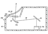
- FIG. 1 It is a schematic diagram which shows the mounting state to the vehicle of the HUD apparatus in 1st Embodiment. It is a mimetic diagram showing a schematic structure of a HUD device in a 1st embodiment. It is a perspective view which shows the structure of the projector in 1st Embodiment. It is a figure for demonstrating the polarization of the light of the image in the 1st Embodiment, and external light. It is a figure for demonstrating the angle of the fast-axis direction in several 4 of 1st Embodiment.
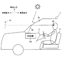
- the HUD device 100 As shown in FIG. 1, the HUD device 100 according to the first embodiment of the present disclosure is mounted on a vehicle 1 and accommodated in an instrument panel 2.
- the HUD device 100 projects an image on a windshield 3 as a projection member of the vehicle 1.
- the HUD device 100 displays a virtual image so that the image can be visually recognized by the passenger of the vehicle 1. That is, the image light reflected by the windshield 3 reaches the occupant's eye point EP in the vehicle 1 and the occupant perceives the image light as a virtual image VI. And a passenger
- Examples of various types of information displayed as virtual images include vehicle state values such as vehicle speed and fuel remaining amount, or navigation information such as road information and visibility assistance information.
- the windshield 3 of the vehicle 1 is located above the instrument panel 2 and is formed in a translucent plate shape with glass or synthetic resin. Further, the windshield 3 is disposed so as to incline toward the rear of the vehicle toward the upper side of the vehicle, and in the windshield 3, the indoor side surface has a projection surface 3 a on which an image is projected as a concave surface or a flat planar shape. Is formed.
- the indoor side surface has a projection surface 3 a on which an image is projected as a concave surface or a flat planar shape. Is formed.
- “above the vehicle” indicates a direction opposite to the direction in which gravity is generated when the vehicle travels on a flat ground or stops on a flat ground.
- the front of the vehicle indicates a direction in which an occupant seated in the seat faces the front.
- the vehicle rear indicates the opposite direction of the vehicle front.
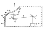
- the HUD device 100 includes a projector 10, a plane mirror 30, a concave mirror 32, a polarizing plate 40 as a polarizer, and a retardation plate 50 as a phaser.
- a projector 10 a plane mirror 30, a concave mirror 32, a polarizing plate 40 as a polarizer, and a retardation plate 50 as a phaser.
- Each element 10, 30, 32, 40, 50 is accommodated in the housing 60 under stable holding.
- the projector 10 includes a light source 12, a condenser lens 14, a diffuser plate 16, a projection lens 18, and a liquid crystal panel 20. It is housed and formed.
- the light source 12 is a plurality of light emitting diode elements, for example, and is disposed on the light source circuit board 12a.
- the light source 12 is electrically connected to a power source through a wiring pattern on the light source circuit board 12a.
- the light source 12 emits light source light with a light emission amount corresponding to a current amount when energized. Thereby, the light source 12 projects the light source light toward the condenser lens 14. More specifically, the light source 12 realizes pseudo white light emission by covering a blue light emitting diode with a phosphor, for example.
- the condenser lens 14 is a translucent convex lens made of synthetic resin or glass, and is disposed between the light source 12 and the diffusion plate 16.
- the condensing lens 14 condenses the light source light from the light source 12 and emits it toward the diffusion plate 16.
- the diffusion plate 16 is a plate formed of synthetic resin or glass, and is disposed between the condenser lens 14 and the projection lens 18.
- the diffusing plate 16 emits light source light whose luminance uniformity is adjusted by diffusion toward the projection lens 18.
- the projection lens 18 is a translucent convex lens made of synthetic resin or glass, and is disposed between the diffusion plate 16 and the liquid crystal panel 20.
- the projection lens 18 condenses the light source light from the diffusion plate 16 and projects it toward the liquid crystal panel 20.
- the liquid crystal panel 20 is a liquid crystal panel using, for example, a thin film transistor (TFT), and is an active matrix type liquid crystal panel formed from a plurality of liquid crystal pixels arranged in a two-dimensional direction.
- TFT thin film transistor
- the polarizing plate has a property of transmitting light polarized along a predetermined direction and blocking light polarized along the predetermined direction, and the pair of polarizing plates are disposed substantially orthogonal to each other.
- the liquid crystal layer can rotate the polarization direction of light incident on the liquid crystal layer in accordance with the applied voltage by applying a voltage for each liquid crystal pixel.
- the projector 10 can project an image.
- the image projected from the projector 10 is projected as light polarized in the direction of the polarization axis 21 as a predetermined direction of the exit side polarizing plate.
- the optical path OP formed by the light of the image is configured from the projector 10 to the windshield 3.
- the plane mirror 30 is a cold mirror that is disposed on the optical path OP and is formed by forming a dielectric multilayer film on the surface of a translucent substrate made of synthetic resin or glass.
- the plane mirror 30 has a property of reflecting visible light and transmitting infrared light and ultraviolet light.
- the plane mirror 30 reflects the light of the image from the projector 10 that is visible light toward the concave mirror 32.
- the concave mirror 32 is disposed on the optical path OP, and is formed by evaporating aluminum as the reflecting surface 32a on the surface of a base material made of synthetic resin or glass.
- the reflecting surface 32a is formed in a smooth flat surface as a concave surface in which the center of the concave mirror 32 is recessed.
- the concave mirror 32 reflects the image light from the plane mirror 30 toward the polarizing plate 40.
- the polarizing plate 40 is a polarizer that is disposed on the optical path OP and is formed into a sheet shape by adding iodine to, for example, polyvinyl alcohol.
- the polarizing plate 40 has a property of transmitting light polarized along the transmission axis 41 and shielding light polarized along the light shielding axis 42 substantially orthogonal to the transmission axis 41.
- the light shielding axis 42 is an absorption axis that absorbs light. Then, the light of the image is transmitted through the polarizing plate 40 and then enters the phase difference plate 50 by setting the transmission axis 41 described later.
- the retardation film 50 is a phase plate that is disposed between the polarizing plate 40 and the windshield 3 on the optical path OP, and is formed into a flat plate shape by, for example, a birefringent material.
- the phase difference plate 50 has an integral plate shape that is bonded to the polarizing plate 40.
- the phase difference plate 50 has a property of changing the polarization direction of transmitted light by causing a phase difference. That is, the phase difference is caused by the light that is polarized in the direction of the fast axis 51 (hereinafter referred to as the fast axis direction DF) more advanced than the light that is polarized in the direction DR of the slow axis 52 substantially orthogonal to the fast axis direction DF.
- the phase difference R of the phase difference plate 50 is set in the range of the following formula 1 using the wavelength ⁇ of the light of the image from the projector 10 as a mathematical expression.
- phase difference R is preferably set so that the following formula 2 is established as a mathematical formula, and is also set as such in the present embodiment.
- 560 nm which is a green wavelength with high sensitivity of the image light, is employed as the wavelength ⁇ in Equations 1 and 2.
- m is an arbitrary integer of 0 or more.
- the dustproof window 62 is provided with a translucent plate 63 made of, for example, acrylic resin, and prevents foreign matter from entering the HUD device 100 from the outside while transmitting image light.
- the setting of the direction of the fast axis of the phase difference plate 50 will be described in detail with reference to FIGS.
- the light of the image from the projector 10 injects into the phase difference plate 50 of 1st Embodiment.
- external light such as sunlight enters the phase difference plate 50 through the windshield 3.
- the S-polarized light reflectance of the windshield 3 is higher than the P-polarized light reflectance, and thus the partially polarized light with a large P-polarized component of the windshield 3 is obtained.
- the incident direction of the windshield 3 changes depending on the direction of the vehicle 1 and the time and the like, but the outside light incident on the HUD device 100 is somewhat Even if there is a direction error, such partial polarization is obtained.
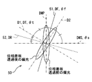
- the fast axis direction DF intersects the direction DT corresponding to the polarization axis 21 of the projector 10, the direction D1 corresponding to the transmission axis 41 of the polarizing plate 40, and the direction DWS corresponding to the S polarization of the windshield 3. Is set. Supplementally, these directions DT, D1, and DWS have a correspondence relationship that intersects the fast axis direction DF on the plate surface of the phase difference plate 50 shown in FIGS.
- the transmission axis 41 of the polarizing plate 40 is arranged along the direction DT corresponding to the polarization axis 21 and coincides with the direction DT, for example.
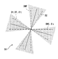
- the angle ⁇ f of the fast axis direction DF is expressed as an equation using the angle ⁇ t of the direction DT corresponding to the polarization axis 21 and the angle ⁇ s of the direction DWS corresponding to the S-polarized light of the windshield 3 as The following range of 3 is set.
- angle ⁇ f is preferably set so that the following formula 4 is established as a mathematical formula, and is also set as such in the present embodiment.
- Equation 4 is an example of the angle ⁇ f in Equation 4.
- the angle ⁇ f in Equation 4 is an angle that is exactly between the angle ⁇ t and the angle ⁇ s.
- the direction of the partially polarized light is the direction corresponding to the P-polarized light of the windshield before passing through the phase difference plate 50 with respect to the wavelength near the wavelength ⁇ of the external light.
- the direction D2 is along the direction D2 corresponding to the light shielding axis.
- the angle ⁇ f satisfies the condition of Equation 4 and thus the same.
- the range of the angle ⁇ f in Equation 3 is illustrated with a period of 90 ° using dots. That is, if the angle ⁇ f is set in the range of Equation 3, the direction of partial polarization is farther from the transmission axis 41 and closer to the light shielding axis 42 than when the phase difference plate 50 is not installed. It is. Note that the solid line in FIG. 6 indicates the angle ⁇ f that satisfies Equation 4.
- the polarization axis 21, the transmission axis 41, the light shielding axis 42, the fast axis 51, and the slow axis 52 are actually formed in the corresponding elements 10, 40, and 50, respectively.
- it is shown at a position away from the optical path OP in order to ensure visibility.
- the polarization direction of the light of the image is indicated by an arrow that overlaps the optical path OP, and the polarization state of the external light is indicated by a circle or an ellipse.
- FIG. 7 is a graph comparing the configuration CA corresponding to the HUD device 100 of the first embodiment and the configuration CB in which the retardation plate 50 is removed from the HUD device 100 as a comparative example. Further, it is shown that the angle of the transmission axis of the polarizing plate is changed for each of the components CA and CB.
- the luminance of the virtual image display is indicated by a solid line
- the sunlight transmittance indicated by the broken line in FIG. 7 is the transmittance of the polarizing plate.
- the angle ⁇ t is set to 135 ° and the angle ⁇ s is set to 169 °.
- the angle ⁇ f is set to 152 ° so as to satisfy Equation 4.
- the maximum luminance is 8,000 cd / m 2 or less in the configuration CB, whereas the maximum luminance is 8,000 cd / m 2 or more in the configuration CA.
- the transmission axis 41 of the polarizing plate 40 is arrange
- the angle of the transmission axis at which the luminance is maximum is different from the angle of the transmission axis at which the sunlight transmittance is minimum.
- the angle of the transmission axis at which the luminance is maximum is substantially the same as the angle of the transmission axis at which the sunlight transmittance is minimum.
- the brightness of the virtual image display and the sunlight transmittance do not change rapidly with respect to the angle of the transmission axis. Therefore, in the configuration CA corresponding to the first embodiment, if the transmission axis of the polarizing plate is arranged along the direction corresponding to the polarization axis, even if the angle difference is about 10 °, it is more than the configuration CB. Sufficiently high brightness and low sunlight transmittance can be realized.
- the phase difference plate 50 is disposed between the polarizing plate 40 and the windshield 3 on the optical path OP formed by the light of the image projected by the projector 10.
- the fast axis direction DF of the phase difference plate 50 is changed to the windshield. Therefore, the direction of the partially polarized light of the external light can be set to be changed in accordance with the polarizing plate 40.
- the direction DT corresponding to the polarization axis 21 and the direction D1 corresponding to the transmission axis 41 intersect with the fast axis direction DF, and projection is performed while efficiently blocking the external light toward the projector 10 side in the polarizing plate 40. It is possible to set the image light from the vessel 10 to be efficiently transmitted to the windshield 3 side. Therefore, it is possible to provide the HUD device 100 that suppresses a temperature increase of the projector 10 while suppressing a decrease in luminance of the virtual image display.
- the transmission axis 41 is arranged along the direction corresponding to the polarization axis 21, and the fast axis direction DF is set so that Equation 3 is established.
- the direction of the partially polarized light of the external light is polarized It changes so as to be surely moved away from the transmission axis 41 when entering the plate 40. Accordingly, it is possible to efficiently block the external light toward the projector 10 in the polarizing plate 40, and to suppress the temperature rise of the projector 10.
- the polarization direction of the image light is efficiently transmitted through the polarizing plate 40 and then changed so as to approach the S-polarized light of the windshield 3 by the phase difference plate 50 and reflected by the windshield 3 with high reflectance. As a result, it is possible to suppress a decrease in luminance of the virtual image display.
- the fast axis direction DF is set so that Formula 4 is established. Then, when the external light transmitted through the windshield 3 is incident on the polarizing plate 40 in a state of being partially polarized in a direction DWP corresponding to the P-polarized light of the windshield 3, for example, the incident light is incident in a state where the direction of the partially polarized light is away from the transmission axis 41. Will be. Therefore, the light of the image is reflected by the windshield 3 as S-polarized light after passing through the polarizing plate 40 with its polarization direction along the transmission axis 41. Therefore, it is possible to provide the HUD device 100 that suppresses a temperature increase of the projector 10 while suppressing a decrease in luminance of the virtual image display.
- phase difference R is set so that Equation 1 is established, it is possible to reliably obtain the effect of suppressing the decrease in the brightness of the virtual image display and the increase in the temperature of the projector 10.
- phase difference R is set so that Equation 2 is established, it is possible to more surely obtain the effect of suppressing the decrease in the brightness of the virtual image display and the increase in the temperature of the projector 10.
- the polarizing plate 40 and the retardation plate 50 are formed as an integrated plate that is bonded to each other, so that the positional relationship between the direction D1 corresponding to the transmission axis 41 and the fast axis direction DF is accurate. It becomes easy to raise. Therefore, it is possible to easily provide the HUD device 100 that suppresses a temperature increase of the projector 10 while suppressing a decrease in luminance of the virtual image display.
- the second embodiment of the present disclosure is a modification of the first embodiment.
- the second embodiment will be described with a focus on differences from the first embodiment.
- the phase difference plate 250 in the HUD device 200 of the second embodiment is a phase retarder that is disposed between the projector 10 and the polarizing plate 240 on the optical path OP and is formed in a flat plate shape.
- the phase difference plate 250 is disposed between the concave mirror 32 and the polarizing plate 240. Similar to the first embodiment, the phase difference plate 250 has a property of changing the polarization direction of transmitted light by generating a phase difference.
- fast axis direction DF the direction of the fast axis 251 substantially orthogonal to the slow axis 252
- the polarizing plate 240 in the second embodiment is a polarizer that is disposed between the retardation plate 250 and the windshield 3 on the optical path OP and is formed in a sheet shape. Then, the light of the image is transmitted through the polarizing plate 240 and then enters the windshield 3 through the dustproof window 62 by setting the transmission axis 241 described later.
- the fast axis direction DF of the phase difference plate 250 will be described in detail with reference to FIG.
- the fast axis direction DF in the second embodiment is a direction DT corresponding to the polarization axis 21 of the projector 10, a direction D1 corresponding to the transmission axis 241 of the polarizing plate 240, and the windshield 3. It is set so as to intersect with the direction DWS corresponding to the S-polarized light.
- these directions DT, D1, and DWS have a correspondence relationship that intersects the fast axis direction DF on the plate surface of the phase difference plate 250.
- the image light from the projector 10 is incident on the polarizing plate 240 of the second embodiment.
- external light such as sunlight enters the polarizing plate 240 through the windshield 3.
- the outside light is partially polarized light with a large amount of P-polarized light component of the windshield 3.
- the transmission axis 241 of the polarizing plate 240 is disposed along the direction DWS corresponding to the S-polarized light of the windshield 3, and coincides with the direction DWS, for example.
- the angle ⁇ f in the fast axis direction DF of the phase difference plate 250 is set to an angle ⁇ t in the direction DT corresponding to the polarization axis 21 and an angle ⁇ s in the direction DWS corresponding to the S polarization of the windshield 3.
- the following formula 5 is set.
- angle ⁇ f is preferably set so that the following formula 6 is established as a mathematical formula, and is also set as such in the present embodiment.
- n is an arbitrary integer. That is, the angle ⁇ f in Expression 6 is an angle that is exactly the middle between the angle ⁇ t and the angle ⁇ s, and when the phase difference R is set as in the first embodiment, the wavelength ⁇ of the external light is set to the wavelength ⁇ . For the nearby wavelengths, the polarization direction of the image light coincides with the transmission axis 241 due to the nature of the retardation plate 250. If the angle ⁇ f is set in the range of Equation 5, the polarization direction of the image light is farther from the light shielding axis 242 and closer to the transmission axis 241 than when the phase difference plate 250 is not installed. It becomes.
- the phase difference plate 250 is disposed between the projector 10 and the polarizing plate 240 on the optical path OP formed by the light of the image projected by the projector 10.
- the light of the image projected by the projector 10 has the fast axis direction DF of the phase difference plate 250 intersecting the direction corresponding to the polarization axis 21, and therefore the polarization direction of the image light is changed.
- the setting can be changed according to the polarizing plate 240.
- the polarizing plate 240 When the external light transmitted through the windshield 3 enters the polarizing plate 240 in a state of being partially polarized in the direction DWP corresponding to the P-polarized light of the windshield 3, for example, the direction D1 corresponding to the transmission axis 241 and the windshield 3 Since the direction DWS corresponding to the S-polarized light intersects the fast axis direction DF, the light of the image from the projector 10 is efficiently windshielded while efficiently blocking the external light toward the projector 10 side. Setting to transmit to the 3 side is possible. Therefore, it is possible to provide the HUD device 200 that suppresses a temperature increase of the projector 10 while suppressing a decrease in luminance of the virtual image display.
- the transmission axis 241 is arranged along the direction DWS corresponding to the S-polarized light of the windshield 3, and the fast axis direction DF is set so that Formula 5 is satisfied.
- the polarization direction of the image light is changed by the phase difference plate 250 so as to approach the transmission axis 241 and the S-polarized light of the windshield 3.
- the light of the image is efficiently transmitted through the polarizing plate 240 and then reflected by the windshield 3 with a high reflectance, so that a decrease in the brightness of the virtual image display can be suppressed.
- the polarizing plate 240 when the external light transmitted through the windshield 3 is incident on the polarizing plate 240 in a state of being partially polarized in a direction corresponding to the P-polarized light of the windshield 3, for example, the light is surely shielded and the temperature rise of the projector 10 is suppressed. be able to.
- the polarizing plate 40 and the retardation film 50 are not bonded to each other, and may be arranged separately from each other.
- the polarizing plate 40 or the retardation film 50 may be disposed between the projector 10 and the concave mirror 32 on the optical path OP.
- the integral plate-like polarizing plate 40 and the phase difference plate 50 may be disposed between the projector 10 and the plane mirror 30 or between the plane mirror 30 and the concave mirror 32.
- the polarizing plate 40 and the retardation plate 50 may be disposed on the optical path OP with the plane mirror 30 or the concave mirror 32 interposed therebetween.
- an optical element such as a lens or a mirror may be additionally arranged on the optical path OP.
- the detailed configuration of the plane mirror 30 or the concave mirror 32 may be changed, or the plane mirror 30 or the concave mirror 32 may be omitted.
Landscapes
- Engineering & Computer Science (AREA)
- Physics & Mathematics (AREA)
- Chemical & Material Sciences (AREA)
- Combustion & Propulsion (AREA)
- Transportation (AREA)
- Mechanical Engineering (AREA)
- General Physics & Mathematics (AREA)
- Optics & Photonics (AREA)
- Instrument Panels (AREA)
- Polarising Elements (AREA)
Priority Applications (4)
| Application Number | Priority Date | Filing Date | Title |
|---|---|---|---|
| CN201680036890.9A CN107735718A (zh) | 2015-06-26 | 2016-06-07 | 平视显示装置 |
| DE112016002856.3T DE112016002856T5 (de) | 2015-06-26 | 2016-06-07 | Head-Up-Display-Vorrichtung |
| US15/736,143 US20180180878A1 (en) | 2015-06-26 | 2016-06-07 | Head-up display device |
| KR1020177033795A KR102022913B1 (ko) | 2015-06-26 | 2016-06-07 | 헤드업 디스플레이 장치 |
Applications Claiming Priority (2)
| Application Number | Priority Date | Filing Date | Title |
|---|---|---|---|
| JP2015-129174 | 2015-06-26 | ||
| JP2015129174A JP6455339B2 (ja) | 2015-06-26 | 2015-06-26 | ヘッドアップディスプレイ装置 |
Publications (1)
| Publication Number | Publication Date |
|---|---|
| WO2016208133A1 true WO2016208133A1 (ja) | 2016-12-29 |
Family
ID=57585512
Family Applications (1)
| Application Number | Title | Priority Date | Filing Date |
|---|---|---|---|
| PCT/JP2016/002741 WO2016208133A1 (ja) | 2015-06-26 | 2016-06-07 | ヘッドアップディスプレイ装置 |
Country Status (6)
Cited By (5)
| Publication number | Priority date | Publication date | Assignee | Title |
|---|---|---|---|---|
| WO2018165126A1 (en) | 2017-03-06 | 2018-09-13 | 3M Innovative Properties Company | Vehicle projection assembly |
| US20190235238A1 (en) * | 2018-01-30 | 2019-08-01 | Samsung Electronics Co., Ltd. | Apparatus for providing heads-up display image |
| US10437056B2 (en) | 2015-06-17 | 2019-10-08 | Denso Corporation | Head-up display device having reflecting mirror with different P and S polarization reflectances |
| WO2021200515A1 (ja) * | 2020-04-03 | 2021-10-07 | マクセル株式会社 | 情報表示装置 |
| US11474350B2 (en) | 2017-04-19 | 2022-10-18 | Continental Automotive Gmbh | Head-up display |
Families Citing this family (25)
| Publication number | Priority date | Publication date | Assignee | Title |
|---|---|---|---|---|
| WO2018047522A1 (ja) * | 2016-09-06 | 2018-03-15 | マクセル株式会社 | ヘッドアップディスプレイ装置とそのための映像表示装置 |
| US20200012100A1 (en) * | 2017-02-28 | 2020-01-09 | Kyocera Corporation | Outdoor image irradiation apparatus and mobile object provided therewith |
| JP2019028373A (ja) * | 2017-08-02 | 2019-02-21 | スリーエム イノベイティブ プロパティズ カンパニー | 表示装置、及び赤外光カットフィルム |
| EP3451044A1 (en) * | 2017-08-28 | 2019-03-06 | Continental Automotive GmbH | Head-up display and method for driving a head-up display |
| CN108761618B (zh) * | 2018-05-23 | 2020-05-19 | 京东方科技集团股份有限公司 | 光学膜片及制作方法、挡风玻璃、驾驶设备 |
| US11320901B2 (en) * | 2018-05-31 | 2022-05-03 | Boe Technology Group Co., Ltd. | Head-up display system and display method, vehicle, head-up display device, and computer-readable storage medium |
| CN108594442A (zh) * | 2018-06-19 | 2018-09-28 | 惠州市华阳多媒体电子有限公司 | 一种减少tft太阳光害的hud光路系统 |
| CN108761797A (zh) * | 2018-07-31 | 2018-11-06 | 惠州市华阳多媒体电子有限公司 | 一种应用于whud的投影模组 |
| JP6947705B2 (ja) * | 2018-08-07 | 2021-10-13 | 本田技研工業株式会社 | 表示装置、表示制御方法、およびプログラム |
| JP7012618B2 (ja) * | 2018-08-07 | 2022-01-28 | 本田技研工業株式会社 | 表示装置、表示制御方法、およびプログラム |
| CN110837185A (zh) * | 2018-08-16 | 2020-02-25 | 宁波舜宇车载光学技术有限公司 | 平视显示系统和平视显示方法 |
| US11135917B2 (en) * | 2018-09-05 | 2021-10-05 | Denso International America, Inc. | Forward collision avoidance display |
| JP7195168B2 (ja) * | 2019-02-08 | 2022-12-23 | 日本化薬株式会社 | 偏光板を備えた画像表示装置 |
| JP7117066B2 (ja) * | 2019-02-15 | 2022-08-12 | マクセル株式会社 | 車両情報表示装置および車両用情報表示システム |
| JP7377609B2 (ja) * | 2019-03-08 | 2023-11-10 | マクセル株式会社 | ヘッドアップディスプレイ装置 |
| WO2021020449A1 (ja) * | 2019-07-29 | 2021-02-04 | 株式会社デンソー | 車両用表示制御装置 |
| KR102316017B1 (ko) * | 2019-08-05 | 2021-10-22 | 주식회사 엘지화학 | 커버 더스트 적층체 및 이를 포함하는 헤드업 디스플레이 |
| KR102577319B1 (ko) * | 2019-08-05 | 2023-09-11 | 주식회사 엘지화학 | 커버 더스트 적층체 및 이를 포함하는 헤드업 디스플레이 |
| WO2021054277A1 (ja) * | 2019-09-19 | 2021-03-25 | 株式会社小糸製作所 | ヘッドアップディスプレイおよび画像表示システム |
| CN113109941B (zh) * | 2020-01-10 | 2023-02-10 | 未来(北京)黑科技有限公司 | 一种分层成像的抬头显示系统 |
| US12181666B2 (en) * | 2020-05-25 | 2024-12-31 | Samsung Electronics Co., Ltd. | System of virtual image projection on screen with effect of eliminating influence of solar radiation |
| US20220171185A1 (en) * | 2020-11-30 | 2022-06-02 | GM Global Technology Operations LLC | Head-up display for mitigating solar loading and back reflection |
| TWI774252B (zh) * | 2021-03-02 | 2022-08-11 | 和碩聯合科技股份有限公司 | 近眼顯示裝置及其製作方法 |
| KR102467924B1 (ko) * | 2021-09-23 | 2022-11-17 | 엘지전자 주식회사 | 헤드 업 디스플레이 |
| WO2023080115A1 (ja) * | 2021-11-05 | 2023-05-11 | 富士フイルム株式会社 | 虚像表示装置、ヘッドアップディスプレイシステム及び輸送機 |
Citations (6)
| Publication number | Priority date | Publication date | Assignee | Title |
|---|---|---|---|---|
| JPS62275845A (ja) * | 1986-05-23 | 1987-11-30 | Nissan Motor Co Ltd | 車両用表示装置 |
| JPH06885U (ja) * | 1992-06-05 | 1994-01-11 | 日本精機株式会社 | 車両用表示装置 |
| JP2000131682A (ja) * | 1998-10-29 | 2000-05-12 | Nippon Seiki Co Ltd | 表示装置 |
| JP2007052383A (ja) * | 2005-07-19 | 2007-03-01 | Sanyo Epson Imaging Devices Corp | ヘッドアップディスプレイシステム |
| JP2007065011A (ja) * | 2005-08-29 | 2007-03-15 | Nippon Seiki Co Ltd | ヘッドアップディスプレイ装置 |
| JP2015225118A (ja) * | 2014-05-26 | 2015-12-14 | 株式会社デンソー | ヘッドアップディスプレイ装置 |
Family Cites Families (14)
| Publication number | Priority date | Publication date | Assignee | Title |
|---|---|---|---|---|
| JPH07195962A (ja) * | 1994-01-10 | 1995-08-01 | Honda Motor Co Ltd | 車両用情報装置 |
| US5486840A (en) * | 1994-03-21 | 1996-01-23 | Delco Electronics Corporation | Head up display with incident light filter |
| WO2003069396A2 (en) * | 2002-02-15 | 2003-08-21 | Elop Electro-Optics Industries Ltd. | Device and method for varying the reflectance or transmittance of light |
| US7482996B2 (en) * | 2004-06-28 | 2009-01-27 | Honeywell International Inc. | Head-up display |
| JP4841815B2 (ja) * | 2004-07-23 | 2011-12-21 | 株式会社村上開明堂 | 表示装置 |
| JP2007131682A (ja) * | 2005-11-08 | 2007-05-31 | Japan Aviation Electronics Industry Ltd | 導電性高分子膜及び回路基板 |
| JP2008070504A (ja) * | 2006-09-13 | 2008-03-27 | Nippon Seiki Co Ltd | 表示装置 |
| CN101952776B (zh) * | 2008-02-04 | 2012-07-25 | 财团法人工业技术研究院 | 显示系统 |
| JP6027727B2 (ja) * | 2011-09-09 | 2016-11-16 | 矢崎総業株式会社 | 車両用表示装置 |
| JP5635571B2 (ja) * | 2011-09-27 | 2014-12-03 | 富士フイルム株式会社 | パターン位相差フィルム、パターン偏光板、画像表示装置、及び立体画像表示システム |
| CN104220921B (zh) * | 2011-11-15 | 2017-06-13 | 美国埃尔比特系统有限责任公司 | 用于从单个投影仪流送多个图像的系统和方法 |
| JP6135048B2 (ja) * | 2012-04-24 | 2017-05-31 | 日本精機株式会社 | ヘッドアップディスプレイ装置 |
| CN103792662B (zh) * | 2014-01-15 | 2016-08-17 | 深圳点石创新科技有限公司 | 一种消重影平视显示装置 |
| CN104880825B (zh) * | 2015-05-15 | 2017-04-19 | 中国计量学院 | 一种平视显示的重影消除方法 |
-
2015
- 2015-06-26 JP JP2015129174A patent/JP6455339B2/ja active Active
-
2016
- 2016-06-07 WO PCT/JP2016/002741 patent/WO2016208133A1/ja active Application Filing
- 2016-06-07 CN CN201680036890.9A patent/CN107735718A/zh active Pending
- 2016-06-07 US US15/736,143 patent/US20180180878A1/en not_active Abandoned
- 2016-06-07 DE DE112016002856.3T patent/DE112016002856T5/de not_active Withdrawn
- 2016-06-07 KR KR1020177033795A patent/KR102022913B1/ko active Active
Patent Citations (6)
| Publication number | Priority date | Publication date | Assignee | Title |
|---|---|---|---|---|
| JPS62275845A (ja) * | 1986-05-23 | 1987-11-30 | Nissan Motor Co Ltd | 車両用表示装置 |
| JPH06885U (ja) * | 1992-06-05 | 1994-01-11 | 日本精機株式会社 | 車両用表示装置 |
| JP2000131682A (ja) * | 1998-10-29 | 2000-05-12 | Nippon Seiki Co Ltd | 表示装置 |
| JP2007052383A (ja) * | 2005-07-19 | 2007-03-01 | Sanyo Epson Imaging Devices Corp | ヘッドアップディスプレイシステム |
| JP2007065011A (ja) * | 2005-08-29 | 2007-03-15 | Nippon Seiki Co Ltd | ヘッドアップディスプレイ装置 |
| JP2015225118A (ja) * | 2014-05-26 | 2015-12-14 | 株式会社デンソー | ヘッドアップディスプレイ装置 |
Cited By (11)
| Publication number | Priority date | Publication date | Assignee | Title |
|---|---|---|---|---|
| US10437056B2 (en) | 2015-06-17 | 2019-10-08 | Denso Corporation | Head-up display device having reflecting mirror with different P and S polarization reflectances |
| WO2018165126A1 (en) | 2017-03-06 | 2018-09-13 | 3M Innovative Properties Company | Vehicle projection assembly |
| CN110392859A (zh) * | 2017-03-06 | 2019-10-29 | 3M创新有限公司 | 车辆投影组件 |
| US11586039B2 (en) | 2017-03-06 | 2023-02-21 | 3M Innovative Properties Company | Vehicle projection assembly |
| CN110392859B (zh) * | 2017-03-06 | 2024-03-08 | 3M创新有限公司 | 车辆投影组件 |
| US11474350B2 (en) | 2017-04-19 | 2022-10-18 | Continental Automotive Gmbh | Head-up display |
| US20190235238A1 (en) * | 2018-01-30 | 2019-08-01 | Samsung Electronics Co., Ltd. | Apparatus for providing heads-up display image |
| US10901207B2 (en) * | 2018-01-30 | 2021-01-26 | Samsung Electronics Co., Ltd. | Apparatus for providing heads-up display image |
| WO2021200515A1 (ja) * | 2020-04-03 | 2021-10-07 | マクセル株式会社 | 情報表示装置 |
| JP2021162801A (ja) * | 2020-04-03 | 2021-10-11 | マクセル株式会社 | 情報表示装置 |
| JP7561512B2 (ja) | 2020-04-03 | 2024-10-04 | マクセル株式会社 | 情報表示装置 |
Also Published As
| Publication number | Publication date |
|---|---|
| KR102022913B1 (ko) | 2019-09-20 |
| CN107735718A (zh) | 2018-02-23 |
| KR20170139629A (ko) | 2017-12-19 |
| JP6455339B2 (ja) | 2019-01-23 |
| DE112016002856T5 (de) | 2018-03-08 |
| US20180180878A1 (en) | 2018-06-28 |
| JP2017015778A (ja) | 2017-01-19 |
Similar Documents
| Publication | Publication Date | Title |
|---|---|---|
| JP6455339B2 (ja) | ヘッドアップディスプレイ装置 | |
| JP6451523B2 (ja) | ヘッドアップディスプレイ装置 | |
| JP6221941B2 (ja) | ヘッドアップディスプレイ装置 | |
| JP6459921B2 (ja) | ヘッドアップディスプレイ装置 | |
| JP6127923B2 (ja) | ヘッドアップディスプレイ装置 | |
| TWI604225B (zh) | 抬頭顯示器光學架構 | |
| EP3385775B1 (en) | Head-up display apparatus | |
| WO2016157815A1 (ja) | ヘッドアップディスプレイ装置 | |
| WO2015162836A1 (ja) | ヘッドアップディスプレイ装置 | |
| JP6481649B2 (ja) | ヘッドアップディスプレイ装置 | |
| WO2017141491A1 (ja) | ヘッドアップディスプレイ装置 | |
| JP2017090822A (ja) | ヘッドアップディスプレイ装置のコールドミラー、およびヘッドアップディスプレイ装置 | |
| TW201337417A (zh) | 顯示器裝置 | |
| US10234684B2 (en) | Projection member, head up display device, and polarized sunglasses | |
| EP3451047B1 (en) | Display apparatus and vehicular head-up display | |
| US10620433B2 (en) | Head-up display device | |
| JP6620706B2 (ja) | ヘッドアップディスプレイ装置 |
Legal Events
| Date | Code | Title | Description |
|---|---|---|---|
| 121 | Ep: the epo has been informed by wipo that ep was designated in this application |
Ref document number: 16813909 Country of ref document: EP Kind code of ref document: A1 |
|
| ENP | Entry into the national phase |
Ref document number: 20177033795 Country of ref document: KR Kind code of ref document: A |
|
| WWE | Wipo information: entry into national phase |
Ref document number: 15736143 Country of ref document: US |
|
| WWE | Wipo information: entry into national phase |
Ref document number: 112016002856 Country of ref document: DE |
|
| 122 | Ep: pct application non-entry in european phase |
Ref document number: 16813909 Country of ref document: EP Kind code of ref document: A1 |