WO2016199333A1 - ワークの加工装置 - Google Patents
ワークの加工装置 Download PDFInfo
- Publication number
- WO2016199333A1 WO2016199333A1 PCT/JP2016/001740 JP2016001740W WO2016199333A1 WO 2016199333 A1 WO2016199333 A1 WO 2016199333A1 JP 2016001740 W JP2016001740 W JP 2016001740W WO 2016199333 A1 WO2016199333 A1 WO 2016199333A1
- Authority
- WO
- WIPO (PCT)
- Prior art keywords
- surface plate
- groove
- workpiece
- polishing
- hook
- Prior art date
- Legal status (The legal status is an assumption and is not a legal conclusion. Google has not performed a legal analysis and makes no representation as to the accuracy of the status listed.)
- Ceased
Links
Images







Classifications
-
- B—PERFORMING OPERATIONS; TRANSPORTING
- B24—GRINDING; POLISHING
- B24B—MACHINES, DEVICES, OR PROCESSES FOR GRINDING OR POLISHING; DRESSING OR CONDITIONING OF ABRADING SURFACES; FEEDING OF GRINDING, POLISHING, OR LAPPING AGENTS
- B24B37/00—Lapping machines or devices; Accessories
- B24B37/04—Lapping machines or devices; Accessories designed for working plane surfaces
- B24B37/07—Lapping machines or devices; Accessories designed for working plane surfaces characterised by the movement of the work or lapping tool
- B24B37/08—Lapping machines or devices; Accessories designed for working plane surfaces characterised by the movement of the work or lapping tool for double side lapping
-
- B—PERFORMING OPERATIONS; TRANSPORTING
- B24—GRINDING; POLISHING
- B24B—MACHINES, DEVICES, OR PROCESSES FOR GRINDING OR POLISHING; DRESSING OR CONDITIONING OF ABRADING SURFACES; FEEDING OF GRINDING, POLISHING, OR LAPPING AGENTS
- B24B37/00—Lapping machines or devices; Accessories
- B24B37/27—Work carriers
- B24B37/28—Work carriers for double side lapping of plane surfaces
-
- B—PERFORMING OPERATIONS; TRANSPORTING
- B24—GRINDING; POLISHING
- B24B—MACHINES, DEVICES, OR PROCESSES FOR GRINDING OR POLISHING; DRESSING OR CONDITIONING OF ABRADING SURFACES; FEEDING OF GRINDING, POLISHING, OR LAPPING AGENTS
- B24B49/00—Measuring or gauging equipment for controlling the feed movement of the grinding tool or work; Arrangements of indicating or measuring equipment, e.g. for indicating the start of the grinding operation
-
- B—PERFORMING OPERATIONS; TRANSPORTING
- B24—GRINDING; POLISHING
- B24B—MACHINES, DEVICES, OR PROCESSES FOR GRINDING OR POLISHING; DRESSING OR CONDITIONING OF ABRADING SURFACES; FEEDING OF GRINDING, POLISHING, OR LAPPING AGENTS
- B24B53/00—Devices or means for dressing or conditioning abrasive surfaces
- B24B53/017—Devices or means for dressing, cleaning or otherwise conditioning lapping tools
-
- H—ELECTRICITY
- H10—SEMICONDUCTOR DEVICES; ELECTRIC SOLID-STATE DEVICES NOT OTHERWISE PROVIDED FOR
- H10P—GENERIC PROCESSES OR APPARATUS FOR THE MANUFACTURE OR TREATMENT OF DEVICES COVERED BY CLASS H10
- H10P52/00—Grinding, lapping or polishing of wafers, substrates or parts of devices
Definitions
- the present invention relates to a workpiece processing apparatus such as a double-side polishing apparatus or a double-sided lapping apparatus that inserts and holds a thin plate-like workpiece such as a silicon wafer in a carrier holding hole and simultaneously processes both surfaces of the workpiece.
- a workpiece processing apparatus such as a double-side polishing apparatus or a double-sided lapping apparatus that inserts and holds a thin plate-like workpiece such as a silicon wafer in a carrier holding hole and simultaneously processes both surfaces of the workpiece.
- a double-side polishing apparatus or a double-sided lapping apparatus has been used when processing a thin plate-like workpiece such as a silicon wafer.
- a disk-shaped carrier having planetary gears on the outer periphery is disposed between upper and lower surface plates to which a polishing pad made of urethane foam or nonwoven fabric is attached.
- the carrier rotates and revolves around the sun gear.
- the work and the upper and lower surface plates are slid to simultaneously polish the upper and lower surfaces of the work.
- polishing slurry is supplied from a plurality of holes provided in the upper surface plate in order to perform polishing efficiently.
- the upper surface plate is provided with a vertical movement mechanism, and the upper surface plate can be moved up and down (for example, Patent Document 1). Place the carrier on the lower surface plate or hold the work on the carrier at the raised position where the upper surface plate is raised. Alternatively, lower the upper surface plate from the raised position, stop the upper surface plate from descending at an intermediate height position to obtain an appropriate gap between the upper surface plate and the lower surface plate, and wash between the upper surface plate and the lower surface plate. Insert a nozzle to clean the polishing surface of the polishing pad. At the intermediate height position, a dresser head is inserted between the upper surface plate and the lower surface plate, and the surface of the polishing pad is adjusted by dressing the polishing surface of the polishing pad.
- a dresser head is inserted between the upper surface plate and the lower surface plate, and the surface of the polishing pad is adjusted by dressing the polishing surface of the polishing pad.
- the cleaning nozzle head and the dresser head When cleaning and dressing the polishing surface of such a polishing pad, the cleaning nozzle head and the dresser head often have a clearly smaller area than the polishing surface of the polishing pad attached to the surface plate.
- These heads are attached to the arm in order to clean and dress the entire polishing surface, and the head can be moved from the outermost circumference to the innermost circumference by moving the arm linearly or pivoting. it can. By rotating the upper and lower surface plates simultaneously with this movement, these heads can clean or dress the entire polishing surface.
- the upper surface plate of a double-side polishing machine or double-sided lapping machine is often connected to a cylinder shaft installed at the upper part of the machine via a universal joint or a spherical bearing so that the angle can be freely changed. This is because when a workpiece is polished, a uniform load can always be applied from the upper surface plate even if the workpiece and the carrier holding the workpiece vary in thickness.
- the present invention has been made in view of the above-described problems, and when the upper surface plate is stopped at a position above the workpiece processing position, the direction perpendicular to the polishing surface of the upper surface plate It is an object of the present invention to provide a workpiece machining apparatus that can maintain an upper surface plate horizontally even when a force is applied.
- a center drum that has at least one first groove formed in an axial direction on an outer peripheral surface and that can rotate around a rotation shaft, and a workpiece to be processed are inserted.
- a carrier having a holding hole for holding, an upper surface plate and a lower surface plate that can rotate around the rotation axis in a state of sandwiching the carrier that holds the work, and an inner peripheral portion of the upper surface plate,
- a workpiece processing apparatus having at least one hook that is movable along the first groove with a tip inserted into the first groove
- the center drum further includes at least one second groove formed in the axial direction on the outer peripheral surface, The second groove has a length different from that of the first groove, and a support surface that supports the hook from below at a position above the position where the upper surface plate processes the workpiece.
- a workpiece processing apparatus characterized by comprising a workpiece.
- the upper surface plate when the upper surface plate is stopped at a position higher than the position where the workpiece is processed by supporting the hook with the support surface of the second groove, Even if a vertical force acts on the polishing surface, the upper surface plate can be kept horizontal. Accordingly, the polishing pad attached to the upper and lower surface plates can be uniformly cleaned and dressed while the upper surface plate is kept horizontal.
- the support surface of the second groove has a surface area capable of supporting at least all of the load of the upper surface plate through the hook.
- the at least one hook, the at least one first groove, and the at least one second groove are each configured as a pair arranged at an angular interval of 180 °. .
- the upper surface plate can be stably supported on the support surface via the hook.
- an angular interval at which the pair of first grooves and the pair of second grooves are arranged on the center drum is 90 °.
- the workpiece processing apparatus may be a double-side polishing apparatus or a double-side lapping apparatus.
- the upper surface plate when the upper surface plate is stopped at a position higher than the position where the workpiece is processed, the upper surface plate rotates or against the polishing surface of the upper surface plate. Even if all vertical forces are applied, the upper surface plate can be kept horizontal. Accordingly, when a treatment such as dressing the polishing pad of the upper surface plate is performed, it can be made to act uniformly, and as a result, the workpiece can be processed with high quality.
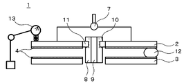
- FIG. 3 is a schematic view showing a method of applying a force in the vertical direction to the polishing surface of the upper surface plate using the air bag in the first embodiment.
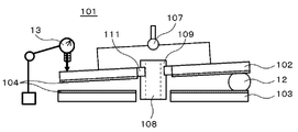
- FIG. 6 is a schematic view showing a method of applying a force in the vertical direction to the polishing surface of the upper surface plate using the air bag in Comparative Example 1.
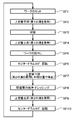
- FIG. 6 is a process diagram showing a process flow when performing double-side polishing and cleaning / dressing of a polished surface in Example 2.
- 6 is a graph showing a relationship between a polishing rate and a batch in Example 2 and Comparative Example 2.
- the comparative example 2 it is the schematic which showed a mode that the polishing pad affixed on the upper and lower surface plate was dressed.
- the present invention is not limited to this.
- the upper surface plate is stopped at a position above the workpiece processing position, if a vertical force acts on the polishing surface of the upper surface plate, the upper surface plate is moved horizontally. There was a problem that could not be maintained.
- the present inventors have intensively studied to solve such problems.
- the center drum having at least one first groove formed in the axial direction on the outer peripheral surface is further formed with at least one second groove in the axial direction on the outer peripheral surface.
- the support surface has a length different from that of the first groove and supports the hook attached to the inner peripheral portion of the upper surface plate from below at a position above the position where the upper surface plate processes the workpiece. It was found to have.
- the workpiece machining apparatus of the present invention will be described in detail.
- Examples of the workpiece processing apparatus of the present invention include a double-side polishing apparatus and a double-side lapping apparatus. If it is such, it can be suitably applied to a manufacturing process of a workpiece such as a silicon wafer which requires a particularly high flatness.
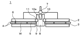
- the double-side polishing apparatus 1 of the present invention includes an upper surface plate 2 and a lower surface plate 3 provided opposite to each other in the upper and lower directions.
- a pad 4 is affixed.
- a sun gear (not shown) is provided at the center between the upper surface plate 2 and the lower surface plate 3, and an internal gear (not shown) is provided at the peripheral portion.
- the carrier 5 has a holding hole 6 for holding the workpiece W.
- the carrier 5 is disposed between the upper surface plate 2 and the lower surface plate 3 with the workpiece W held in the holding hole 6.
- the upper surface plate 2 is connected to a cylinder shaft (not shown) installed at the upper part of the apparatus via a universal joint 7 and a spherical bearing so that the angle can be freely changed.
- a universal joint 7 is used as an example.
- the center drum 8 is rotatable around the rotation axis.
- the center drum 8 has at least one first groove 9 formed in the axial direction on the outer peripheral surface.
- At least one hook 11 is attached to the inner periphery of the upper surface plate 2.
- the tip of the hook 11 is inserted into the first groove 9 and can move along the first groove 9.
- the upper and lower polishing pads 4 are pressed against both the front and back surfaces of the workpiece W, and the carrier 5 holding the workpiece W is rotated and revolved to simultaneously rotate both surfaces of the workpiece W. Can be polished.
- the center drum 8 further has at least one second groove 10 formed in the axial direction on the outer peripheral surface.
- the second groove 10 has a length different from that of the first groove 9, and is a support surface 10 a that supports the hook 11 from below at a position above the position where the upper surface plate 2 processes the workpiece W.
- the length of the second groove 10 is shorter than that of the first groove 9.
- the first groove 9 has a length sufficient for the upper surface plate 2 to contact the workpiece W, the carrier 5 and the lower surface plate 3.
- the hook 11 When the hook 11 is inserted into and fitted into the second groove 10 and the upper surface plate 2 is lowered, the hook 11 contacts the support surface 10a at the lower end of the second groove 10, so that the upper surface plate 2 is more than that. The descent cannot continue. Therefore, the upper surface plate 2 stops at an intermediate height position where the hook 11 is in contact with the support surface 10a. At this intermediate height position, the polishing surfaces of the upper and lower surface plates 2 and 3 can be cleaned and dressed.
- the support surface 10 a of the second groove 10 preferably has a surface area that can support at least all of the load of the upper surface plate 2 via the hook 11. .
- the upper surface plate 2 can be kept horizontal.
- the second groove 10 can be cut out and the support surface 10a can be flat.
- the support surface 10a can be flat.
- the hook 11, the first groove 9, and the second groove 10 are configured as a pair arranged at an angular interval of 180 °.
- the upper surface plate 2 can be held by the support surfaces 10 a of the two second grooves 10 facing each other at 180 ° via the hook 11. As described above, since all or a part of the load of the upper surface plate 2 stopped at the intermediate height position is supported at two points, the upper surface plate 2 can be stably supported. It is possible to remarkably improve the height position at which the movement is stopped and the maintenance stability of the inclination.
- the angular interval at which the pair of first grooves 9 and the pair of second grooves 10 are arranged in the center drum 8 is 90 °. .
- the first groove 9 and the second groove 10 can be easily switched.
- the upper surface plate 2 is first lifted, and the hook 11 is completely pulled out of the first groove 9. At this time, since the upper surface plate 2 does not rotate, the position of the hook 11 remains constant.
- the center drum 8 is rotated by 90 ° in this state and then the upper surface plate 2 is lowered, the hook 11 is inserted into the second groove 10. In this way, switching from the first groove 9 to the second groove 10 can be performed.
- two grooves of two lengths, the first groove 9 and the second groove 10 are arranged in the center drum 8 at 90 ° intervals, for example, but the first groove 9 is, for example, And the second grooves 10 may be arranged three by three, and a total of six may be arranged at intervals of 60 °. In this way, it is possible to further increase the stability of the height and inclination of the surface plate 2 when the upper surface plate 2 is stopped at the intermediate height position. If it is desired to stop at two intermediate height positions, two types of second grooves 10 may be provided.
- the double-side polishing apparatus of the present invention as described above, when the upper surface plate is stopped at a position above the position where the workpiece is processed, the upper surface plate rotates or the upper surface plate is polished. Even if a vertical force is applied to the surface, the upper surface plate can be kept horizontal. Accordingly, the polishing pad attached to the upper and lower surface plates can be uniformly cleaned and dressed while the upper surface plate is kept horizontal. Therefore, the work can be polished with high quality by using the double-side polishing apparatus in which dressing and cleaning are performed uniformly as described above.
- the workpiece processing apparatus of the present invention has been described by taking the case of a double-side polishing apparatus as an example, but it can also be applied to a double-sided lapping apparatus, and can achieve the same effects as described above.
- Example 1 When a vertical force is applied to the polishing surface of the upper surface plate 2 when the upper surface plate 2 is stopped at the intermediate height position by using the double-side polishing apparatus 1 of the present invention shown in FIG. The stability of the upper surface plate 2 was examined.
- the upper surface plate 2 was stopped at an intermediate position, and the air bag 12 was inserted between the upper surface plate 2 and the lower surface plate 3. Then, the pressure to increase the pressure of the air bag 12 was increased to push up the upper surface plate 2.
- Example 1 As a result, as shown in FIG. 6, in Example 1, that is, when the load of the upper surface plate is supported by the bottom surface of the short groove, the fluctuation of the height of the upper surface plate on the side opposite to the airbag is a comparative example. Compared to 1, it was reduced to about 1/10.
- the hook 11 contacts the support surface 10a of the second groove 10 and supports the upper surface plate 2 with the support surface 10a.
- the surface plate 2 did not tilt, and as a result, the height of the upper surface plate 2 measured on the opposite side hardly changed.
- the double-side polishing apparatus 101 includes an upper surface plate 102 and a lower surface plate 103 that are provided opposite to each other vertically, and a polishing pad 104 is attached to each surface plate 102, 103.
- the upper surface plate 102 is connected to a universal joint 107 so that its angle can be freely changed.
- the hook 111 provided on the upper surface plate 102 was inserted into the first groove 109 provided on the center drum 108, and the upper surface plate 102 was lowered and stopped at the intermediate height position. And the airbag 12 was inserted between the upper surface plate 102 and the lower surface plate 103, the pressure of the air bag 12 was increased, and the same measurement as Example 1 was performed. The results at this time are shown in FIG. 6 as described above.
- the hook 11 is inserted into the first groove 9, the workpiece W is polished on both sides, the workpiece W is taken out, and the polishing pad 4 attached to the upper and lower surface plates 2 and 3 is polished. The surface was cleaned and dressed. Dressing was performed by inserting the hook 11 into the second groove 10 and inserting the dress head 14 between the upper surface plate 2 and the lower surface plate 3 as shown in FIG.
- the workpiece is set (SP1), the upper platen is lowered (using a long groove) (SP2), the polishing (SP3), the upper platen is raised (SP4), and the workpiece is taken out (SP5).
- SP6 Center drum 90 ° rotation
- SP7 upper platen lowering (use of short groove, intermediate position stop)
- SP8 polishing surface cleaning / dressing
- SP9 center drum 90 ° rotation
- the order was SP10). And it returned to SP1 again after SP10, and this was performed 30 batches continuously.
- FIG. 10 also shows the results of Comparative Example 2 described later.
- GBIR Global Backsurface-referenced ideal plane / Range
- SFQRmax Site Frontsurface reference sQuares / Range
- Example 2 As a result, as shown in FIG. 10, assuming that the polishing rate immediately after the start of continuous polishing was 100, the rate of decrease of the polishing rate in Example 2 after 30 batches was only about 2%. Further, GBIR and SFQRmax, which indicate the flatness of the workpiece after double-side polishing, were improved by 4.2% and 6.0% in Example 2, respectively, as compared with Comparative Example 2.
- Example 2 the relationship between the number of batches and the polishing rate at this time was measured and shown in FIG. 10 as described above. Further, GBIR and SFQRmax were set as the flatness of the workpiece W subjected to double-side polishing. It was measured.
- the present invention is not limited to the above embodiment.
- the above-described embodiment is an exemplification, and the present invention has any configuration that has substantially the same configuration as the technical idea described in the claims of the present invention and that exhibits the same effects. Are included in the technical scope.
Landscapes
- Engineering & Computer Science (AREA)
- Mechanical Engineering (AREA)
- Finish Polishing, Edge Sharpening, And Grinding By Specific Grinding Devices (AREA)
- Mechanical Treatment Of Semiconductor (AREA)
Abstract
Description
前記センタードラムは、さらに、前記外周面に軸方向に形成された少なくとも1つの第2の溝を有し、
該第2の溝は、前記第1の溝と異なる長さを有し、前記上定盤が前記ワークの加工を行う位置よりも上方となる位置で、前記フックを下方から支持する支持面を有するものであることを特徴とするワークの加工装置を提供する。
上述したように、ワークの加工を行う位置よりも上方となる位置で上定盤を停止させた際に、上定盤の研磨面に対して垂直方向の力が作用すると、上定盤を水平に維持することができないという問題があった。
このようなものであれば、特に高平坦度が要求されるシリコンウェーハ等のワークの製造プロセスに好適に適応できる。
図1に示すように、本発明の両面研磨装置1は、上下に相対向して設けられた上定盤2と下定盤3を備えており、各上下定盤2、3には、それぞれ研磨パッド4が貼付されている。上定盤2と下定盤3の間の中心部にはサンギア(不図示)が、周縁部にはインターナルギア(不図示)が設けられている。
図1に示した本発明の両面研磨装置1を用いて、上定盤2を中間高さ位置に停止させた際に、上定盤2の研磨面に対して垂直方向の力を掛けた際の上定盤2の安定性を調べた。
図7に示すように、両面研磨装置101は、上下に相対向して設けられた上定盤102と下定盤103を備えており、各定盤102、103には、それぞれ研磨パッド104が貼付されている。上定盤102は、ユニバーサルジョイント107に接続され、その角度を自由に変えられるようになっている。
図11に示すような、両面研磨装置101を用いて、第1の溝109を用いて中間高さ位置でドレッシングを行ったこと以外は、実施例2と同様にして、ワークWの両面研磨及び、研磨パッド104の研磨面の洗浄・ドレッシングを繰り返し行った。即ち、図9におけるSP6とSP10を行わなかった。
Claims (5)
- 外周面に軸方向に形成された少なくとも1つの第1の溝を有する回転軸周りに回転可能なセンタードラムと、加工するワークを挿入して保持する保持孔を有するキャリアと、前記ワークを保持した前記キャリアを挟んだ状態で、前記回転軸周りに回転可能な上定盤及び下定盤と、前記上定盤の内周部に取り付けられ、前記第1の溝に挿入した先端部を前記第1の溝に沿って移動可能な少なくとも1つのフックを有するワークの加工装置であって、
前記センタードラムは、さらに、前記外周面に軸方向に形成された少なくとも1つの第2の溝を有し、
該第2の溝は、前記第1の溝と異なる長さを有し、前記上定盤が前記ワークの加工を行う位置よりも上方となる位置で、前記フックを下方から支持する支持面を有するものであることを特徴とするワークの加工装置。 - 前記第2の溝の前記支持面は、前記フックを介して少なくとも前記上定盤の荷重の全てを支持することができる表面積を有するものであることを特徴とする請求項1に記載のワークの加工装置。
- 前記少なくとも1つのフック、前記少なくとも1つの第1の溝、及び前記少なくとも1つの第2の溝は、それぞれが180°の角度間隔で配置される一対で構成させるものであることを特徴とする請求項1又は請求項2に記載のワークの加工装置。
- 前記センタードラムに、前記一対の第1の溝と前記一対の第2の溝とが配置される角度間隔は、90°であることを特徴とする請求項3に記載のワークの加工装置。
- 前記ワークの加工装置は、両面研磨装置または両面ラップ装置であることを特徴とする請求項1から請求項4のいずれか一項に記載のワークの加工装置。
Priority Applications (5)
| Application Number | Priority Date | Filing Date | Title |
|---|---|---|---|
| US15/572,747 US10335918B2 (en) | 2015-06-12 | 2016-03-25 | Workpiece processing apparatus |
| KR1020177034812A KR102291381B1 (ko) | 2015-06-12 | 2016-03-25 | 워크의 가공장치 |
| DE112016002162.3T DE112016002162T5 (de) | 2015-06-12 | 2016-03-25 | Vorrichtung zum Bearbeiten eines Werkstücks |
| SG11201709412PA SG11201709412PA (en) | 2015-06-12 | 2016-03-25 | Workpiece processing apparatus |
| CN201680029025.1A CN107614199B (zh) | 2015-06-12 | 2016-03-25 | 工件的加工装置 |
Applications Claiming Priority (2)
| Application Number | Priority Date | Filing Date | Title |
|---|---|---|---|
| JP2015119338A JP6304132B2 (ja) | 2015-06-12 | 2015-06-12 | ワークの加工装置 |
| JP2015-119338 | 2015-06-12 |
Publications (1)
| Publication Number | Publication Date |
|---|---|
| WO2016199333A1 true WO2016199333A1 (ja) | 2016-12-15 |
Family
ID=57503434
Family Applications (1)
| Application Number | Title | Priority Date | Filing Date |
|---|---|---|---|
| PCT/JP2016/001740 Ceased WO2016199333A1 (ja) | 2015-06-12 | 2016-03-25 | ワークの加工装置 |
Country Status (8)
| Country | Link |
|---|---|
| US (1) | US10335918B2 (ja) |
| JP (1) | JP6304132B2 (ja) |
| KR (1) | KR102291381B1 (ja) |
| CN (1) | CN107614199B (ja) |
| DE (1) | DE112016002162T5 (ja) |
| SG (1) | SG11201709412PA (ja) |
| TW (1) | TWI682832B (ja) |
| WO (1) | WO2016199333A1 (ja) |
Families Citing this family (11)
| Publication number | Priority date | Publication date | Assignee | Title |
|---|---|---|---|---|
| JP6829467B2 (ja) * | 2017-04-05 | 2021-02-10 | スピードファム株式会社 | 両面研磨装置 |
| KR101941769B1 (ko) * | 2017-04-19 | 2019-01-23 | 에스케이실트론 주식회사 | 웨이퍼의 양면 연마장치 |
| KR101941768B1 (ko) * | 2017-04-19 | 2019-01-23 | 에스케이실트론 주식회사 | 웨이퍼의 양면 연마장치 |
| KR101993515B1 (ko) * | 2017-05-11 | 2019-06-26 | 에스케이실트론 주식회사 | 웨이퍼의 양면 연마장치 |
| JP6451825B1 (ja) * | 2017-12-25 | 2019-01-16 | 株式会社Sumco | ウェーハの両面研磨方法 |
| CN108481185B (zh) * | 2018-06-14 | 2024-11-22 | 东莞金研精密研磨机械制造有限公司 | 一种双面研磨机 |
| JP2020171996A (ja) * | 2019-04-11 | 2020-10-22 | 信越半導体株式会社 | 両面研磨方法 |
| KR102705647B1 (ko) * | 2019-05-02 | 2024-09-11 | 삼성전자주식회사 | 컨디셔너, 이를 포함하는 화학 기계적 연마 장치 및 이 장치를 이용한 반도체 장치의 제조 방법 |
| JP7308074B2 (ja) * | 2019-05-14 | 2023-07-13 | 東京エレクトロン株式会社 | 基板処理装置及び基板処理方法 |
| US11801580B1 (en) | 2019-12-16 | 2023-10-31 | Arc Specialties, Inc. | Dual airbag compliance device for ball and seat lapping |
| JP6885492B1 (ja) * | 2020-05-13 | 2021-06-16 | 信越半導体株式会社 | 両面研磨方法 |
Citations (2)
| Publication number | Priority date | Publication date | Assignee | Title |
|---|---|---|---|---|
| JPS5946667U (ja) * | 1982-09-16 | 1984-03-28 | 株式会社東芝 | ポリシヤの研磨布ブラツシング装置 |
| JP2001038603A (ja) * | 1999-08-04 | 2001-02-13 | Speedfam Co Ltd | ドレッサ,ドレッサ付き研磨装置及びドレッシング方法 |
Family Cites Families (12)
| Publication number | Priority date | Publication date | Assignee | Title |
|---|---|---|---|---|
| JP2535089B2 (ja) * | 1990-04-27 | 1996-09-18 | 昭和アルミニウム株式会社 | 研磨方法及び研磨装置 |
| JPH0425372A (ja) * | 1990-05-17 | 1992-01-29 | Seiko Electronic Components Ltd | 両面研磨装置 |
| JP3808156B2 (ja) | 1997-02-24 | 2006-08-09 | 不二越機械工業株式会社 | 両面研磨装置 |
| JPH11254308A (ja) * | 1998-03-06 | 1999-09-21 | Fujikoshi Mach Corp | 両面研磨装置 |
| JP2984263B1 (ja) | 1998-10-23 | 1999-11-29 | システム精工株式会社 | 研磨方法および研磨装置 |
| JP2002154049A (ja) * | 2000-11-15 | 2002-05-28 | Fujikoshi Mach Corp | 研磨方法 |
| JP4183086B2 (ja) * | 2001-12-26 | 2008-11-19 | 光洋機械工業株式会社 | 研削砥石のツルーイング方法、そのツルーイング装置および研削装置 |
| DE102007056627B4 (de) * | 2007-03-19 | 2023-12-21 | Lapmaster Wolters Gmbh | Verfahren zum gleichzeitigen Schleifen mehrerer Halbleiterscheiben |
| DE102009038942B4 (de) * | 2008-10-22 | 2022-06-23 | Peter Wolters Gmbh | Vorrichtung zur beidseitigen Bearbeitung von flachen Werkstücken sowie Verfahren zur gleichzeitigen beidseitigen Material abtragenden Bearbeitung mehrerer Halbleiterscheiben |
| JP5399115B2 (ja) * | 2009-03-31 | 2014-01-29 | Hoya株式会社 | 研磨装置、ガラス基材の研磨方法及びガラス基板の製造方法 |
| JP5533355B2 (ja) * | 2010-07-01 | 2014-06-25 | 旭硝子株式会社 | 磁気記録媒体用ガラス基板、両面研磨装置、ガラス基板の研磨方法及びガラス基板の製造方法 |
| KR20140083317A (ko) * | 2012-12-26 | 2014-07-04 | 주식회사 엘지실트론 | 선기어 유닛 및 이를 포함한 연마 장치 |
-
2015
- 2015-06-12 JP JP2015119338A patent/JP6304132B2/ja active Active
-
2016
- 2016-03-25 WO PCT/JP2016/001740 patent/WO2016199333A1/ja not_active Ceased
- 2016-03-25 US US15/572,747 patent/US10335918B2/en active Active
- 2016-03-25 DE DE112016002162.3T patent/DE112016002162T5/de active Granted
- 2016-03-25 CN CN201680029025.1A patent/CN107614199B/zh active Active
- 2016-03-25 KR KR1020177034812A patent/KR102291381B1/ko active Active
- 2016-03-25 SG SG11201709412PA patent/SG11201709412PA/en unknown
- 2016-03-28 TW TW105109674A patent/TWI682832B/zh active
Patent Citations (2)
| Publication number | Priority date | Publication date | Assignee | Title |
|---|---|---|---|---|
| JPS5946667U (ja) * | 1982-09-16 | 1984-03-28 | 株式会社東芝 | ポリシヤの研磨布ブラツシング装置 |
| JP2001038603A (ja) * | 1999-08-04 | 2001-02-13 | Speedfam Co Ltd | ドレッサ,ドレッサ付き研磨装置及びドレッシング方法 |
Also Published As
| Publication number | Publication date |
|---|---|
| SG11201709412PA (en) | 2017-12-28 |
| JP6304132B2 (ja) | 2018-04-04 |
| KR102291381B1 (ko) | 2021-08-20 |
| US10335918B2 (en) | 2019-07-02 |
| US20180117729A1 (en) | 2018-05-03 |
| TWI682832B (zh) | 2020-01-21 |
| CN107614199B (zh) | 2019-10-25 |
| TW201710027A (zh) | 2017-03-16 |
| JP2017001151A (ja) | 2017-01-05 |
| DE112016002162T5 (de) | 2018-02-15 |
| KR20180017004A (ko) | 2018-02-20 |
| CN107614199A (zh) | 2018-01-19 |
Similar Documents
| Publication | Publication Date | Title |
|---|---|---|
| JP6304132B2 (ja) | ワークの加工装置 | |
| EP2762272B1 (en) | Wafer polishing apparatus and method | |
| US6168506B1 (en) | Apparatus for polishing using improved plate supports | |
| JP2023017278A (ja) | 硬質ウェーハの研削方法 | |
| KR20100115819A (ko) | 연마 장치, 연마 보조 장치 및 연마 방법 | |
| CN106335004B (zh) | 供双面研磨装置的研磨垫用的修整装置和修整方法 | |
| KR102560432B1 (ko) | 연마패드의 컨디셔닝방법 및 연마장치 | |
| TW202233356A (zh) | 雙面研磨裝置及研磨布之修整方法 | |
| JP6271339B2 (ja) | 研削研磨装置 | |
| CN102922414B (zh) | 化学机械抛光装置 | |
| JP2006147731A (ja) | 研磨クロス,ウェーハ研磨装置及びウェーハ製造方法 | |
| US12337439B2 (en) | Multiple disk pad conditioner | |
| WO2006132725A1 (en) | Conditioning element for electrochemical mechanical processing | |
| JP2018164052A (ja) | ウェハ加工システム | |
| JP5578519B2 (ja) | 研磨装置および研磨方法 | |
| US7175515B2 (en) | Static pad conditioner | |
| JP2014200868A (ja) | 研磨装置 | |
| KR20170087300A (ko) | 에지 그라인딩 장치 | |
| JP2000288908A (ja) | 研磨装置及び研磨方法 | |
| JP2001144057A (ja) | 研磨装置及び被研磨材の研磨方法 | |
| JP5294054B2 (ja) | 研磨装置 | |
| JP6888753B2 (ja) | 研磨装置、及び、研磨パッドのドレッシング方法 | |
| KR20260065222A (ko) | 웨이퍼 랩핑 장치의 드레싱 장치 | |
| JP6298681B2 (ja) | 研磨装置、研磨パッドのドレス方法 | |
| JP2013230533A (ja) | 研磨機用定盤の表面加工方法および研磨機用定盤 |
Legal Events
| Date | Code | Title | Description |
|---|---|---|---|
| 121 | Ep: the epo has been informed by wipo that ep was designated in this application |
Ref document number: 16807053 Country of ref document: EP Kind code of ref document: A1 |
|
| WWE | Wipo information: entry into national phase |
Ref document number: 15572747 Country of ref document: US |
|
| WWE | Wipo information: entry into national phase |
Ref document number: 11201709412P Country of ref document: SG |
|
| ENP | Entry into the national phase |
Ref document number: 20177034812 Country of ref document: KR Kind code of ref document: A |
|
| WWE | Wipo information: entry into national phase |
Ref document number: 112016002162 Country of ref document: DE |
|
| 122 | Ep: pct application non-entry in european phase |
Ref document number: 16807053 Country of ref document: EP Kind code of ref document: A1 |