WO2016190443A1 - 切削工具 - Google Patents
切削工具 Download PDFInfo
- Publication number
- WO2016190443A1 WO2016190443A1 PCT/JP2016/065847 JP2016065847W WO2016190443A1 WO 2016190443 A1 WO2016190443 A1 WO 2016190443A1 JP 2016065847 W JP2016065847 W JP 2016065847W WO 2016190443 A1 WO2016190443 A1 WO 2016190443A1
- Authority
- WO
- WIPO (PCT)
- Prior art keywords
- region
- dlc layer
- thickness
- cutting tool
- layer
- Prior art date
- Legal status (The legal status is an assumption and is not a legal conclusion. Google has not performed a legal analysis and makes no representation as to the accuracy of the status listed.)
- Ceased
Links
Images
Classifications
-
- C—CHEMISTRY; METALLURGY
- C23—COATING METALLIC MATERIAL; COATING MATERIAL WITH METALLIC MATERIAL; CHEMICAL SURFACE TREATMENT; DIFFUSION TREATMENT OF METALLIC MATERIAL; COATING BY VACUUM EVAPORATION, BY SPUTTERING, BY ION IMPLANTATION OR BY CHEMICAL VAPOUR DEPOSITION, IN GENERAL; INHIBITING CORROSION OF METALLIC MATERIAL OR INCRUSTATION IN GENERAL
- C23C—COATING METALLIC MATERIAL; COATING MATERIAL WITH METALLIC MATERIAL; SURFACE TREATMENT OF METALLIC MATERIAL BY DIFFUSION INTO THE SURFACE, BY CHEMICAL CONVERSION OR SUBSTITUTION; COATING BY VACUUM EVAPORATION, BY SPUTTERING, BY ION IMPLANTATION OR BY CHEMICAL VAPOUR DEPOSITION, IN GENERAL
- C23C14/00—Coating by vacuum evaporation, by sputtering or by ion implantation of the coating forming material
- C23C14/06—Coating by vacuum evaporation, by sputtering or by ion implantation of the coating forming material characterised by the coating material
- C23C14/0605—Carbon
-
- B—PERFORMING OPERATIONS; TRANSPORTING
- B23—MACHINE TOOLS; METAL-WORKING NOT OTHERWISE PROVIDED FOR
- B23B—TURNING; BORING
- B23B27/00—Tools for turning or boring machines; Tools of a similar kind in general; Accessories therefor
- B23B27/14—Cutting tools of which the bits or tips or cutting inserts are of special material
- B23B27/148—Composition of the cutting inserts
-
- C—CHEMISTRY; METALLURGY
- C23—COATING METALLIC MATERIAL; COATING MATERIAL WITH METALLIC MATERIAL; CHEMICAL SURFACE TREATMENT; DIFFUSION TREATMENT OF METALLIC MATERIAL; COATING BY VACUUM EVAPORATION, BY SPUTTERING, BY ION IMPLANTATION OR BY CHEMICAL VAPOUR DEPOSITION, IN GENERAL; INHIBITING CORROSION OF METALLIC MATERIAL OR INCRUSTATION IN GENERAL
- C23C—COATING METALLIC MATERIAL; COATING MATERIAL WITH METALLIC MATERIAL; SURFACE TREATMENT OF METALLIC MATERIAL BY DIFFUSION INTO THE SURFACE, BY CHEMICAL CONVERSION OR SUBSTITUTION; COATING BY VACUUM EVAPORATION, BY SPUTTERING, BY ION IMPLANTATION OR BY CHEMICAL VAPOUR DEPOSITION, IN GENERAL
- C23C14/00—Coating by vacuum evaporation, by sputtering or by ion implantation of the coating forming material
- C23C14/22—Coating by vacuum evaporation, by sputtering or by ion implantation of the coating forming material characterised by the process of coating
- C23C14/24—Vacuum evaporation
- C23C14/32—Vacuum evaporation by explosion; by evaporation and subsequent ionisation of the vapours, e.g. ion-plating
- C23C14/325—Electric arc evaporation
-
- C—CHEMISTRY; METALLURGY
- C23—COATING METALLIC MATERIAL; COATING MATERIAL WITH METALLIC MATERIAL; CHEMICAL SURFACE TREATMENT; DIFFUSION TREATMENT OF METALLIC MATERIAL; COATING BY VACUUM EVAPORATION, BY SPUTTERING, BY ION IMPLANTATION OR BY CHEMICAL VAPOUR DEPOSITION, IN GENERAL; INHIBITING CORROSION OF METALLIC MATERIAL OR INCRUSTATION IN GENERAL
- C23C—COATING METALLIC MATERIAL; COATING MATERIAL WITH METALLIC MATERIAL; SURFACE TREATMENT OF METALLIC MATERIAL BY DIFFUSION INTO THE SURFACE, BY CHEMICAL CONVERSION OR SUBSTITUTION; COATING BY VACUUM EVAPORATION, BY SPUTTERING, BY ION IMPLANTATION OR BY CHEMICAL VAPOUR DEPOSITION, IN GENERAL
- C23C16/00—Chemical coating by decomposition of gaseous compounds, without leaving reaction products of surface material in the coating, i.e. chemical vapour deposition [CVD] processes
- C23C16/22—Chemical coating by decomposition of gaseous compounds, without leaving reaction products of surface material in the coating, i.e. chemical vapour deposition [CVD] processes characterised by the deposition of inorganic material, other than metallic material
- C23C16/26—Deposition of carbon only
-
- C—CHEMISTRY; METALLURGY
- C23—COATING METALLIC MATERIAL; COATING MATERIAL WITH METALLIC MATERIAL; CHEMICAL SURFACE TREATMENT; DIFFUSION TREATMENT OF METALLIC MATERIAL; COATING BY VACUUM EVAPORATION, BY SPUTTERING, BY ION IMPLANTATION OR BY CHEMICAL VAPOUR DEPOSITION, IN GENERAL; INHIBITING CORROSION OF METALLIC MATERIAL OR INCRUSTATION IN GENERAL
- C23C—COATING METALLIC MATERIAL; COATING MATERIAL WITH METALLIC MATERIAL; SURFACE TREATMENT OF METALLIC MATERIAL BY DIFFUSION INTO THE SURFACE, BY CHEMICAL CONVERSION OR SUBSTITUTION; COATING BY VACUUM EVAPORATION, BY SPUTTERING, BY ION IMPLANTATION OR BY CHEMICAL VAPOUR DEPOSITION, IN GENERAL
- C23C16/00—Chemical coating by decomposition of gaseous compounds, without leaving reaction products of surface material in the coating, i.e. chemical vapour deposition [CVD] processes
- C23C16/44—Chemical coating by decomposition of gaseous compounds, without leaving reaction products of surface material in the coating, i.e. chemical vapour deposition [CVD] processes characterised by the method of coating
- C23C16/50—Chemical coating by decomposition of gaseous compounds, without leaving reaction products of surface material in the coating, i.e. chemical vapour deposition [CVD] processes characterised by the method of coating using electric discharges
- C23C16/503—Chemical coating by decomposition of gaseous compounds, without leaving reaction products of surface material in the coating, i.e. chemical vapour deposition [CVD] processes characterised by the method of coating using electric discharges using DC or AC discharges
-
- C—CHEMISTRY; METALLURGY
- C23—COATING METALLIC MATERIAL; COATING MATERIAL WITH METALLIC MATERIAL; CHEMICAL SURFACE TREATMENT; DIFFUSION TREATMENT OF METALLIC MATERIAL; COATING BY VACUUM EVAPORATION, BY SPUTTERING, BY ION IMPLANTATION OR BY CHEMICAL VAPOUR DEPOSITION, IN GENERAL; INHIBITING CORROSION OF METALLIC MATERIAL OR INCRUSTATION IN GENERAL
- C23C—COATING METALLIC MATERIAL; COATING MATERIAL WITH METALLIC MATERIAL; SURFACE TREATMENT OF METALLIC MATERIAL BY DIFFUSION INTO THE SURFACE, BY CHEMICAL CONVERSION OR SUBSTITUTION; COATING BY VACUUM EVAPORATION, BY SPUTTERING, BY ION IMPLANTATION OR BY CHEMICAL VAPOUR DEPOSITION, IN GENERAL
- C23C28/00—Coating for obtaining at least two superposed coatings either by methods not provided for in a single one of groups C23C2/00 - C23C26/00 or by combinations of methods provided for in subclasses C23C and C25C or C25D
- C23C28/04—Coating for obtaining at least two superposed coatings either by methods not provided for in a single one of groups C23C2/00 - C23C26/00 or by combinations of methods provided for in subclasses C23C and C25C or C25D only coatings of inorganic non-metallic material
- C23C28/046—Coating for obtaining at least two superposed coatings either by methods not provided for in a single one of groups C23C2/00 - C23C26/00 or by combinations of methods provided for in subclasses C23C and C25C or C25D only coatings of inorganic non-metallic material with at least one amorphous inorganic material layer, e.g. DLC, a-C:H, a-C:Me, the layer being doped or not
-
- C—CHEMISTRY; METALLURGY
- C23—COATING METALLIC MATERIAL; COATING MATERIAL WITH METALLIC MATERIAL; CHEMICAL SURFACE TREATMENT; DIFFUSION TREATMENT OF METALLIC MATERIAL; COATING BY VACUUM EVAPORATION, BY SPUTTERING, BY ION IMPLANTATION OR BY CHEMICAL VAPOUR DEPOSITION, IN GENERAL; INHIBITING CORROSION OF METALLIC MATERIAL OR INCRUSTATION IN GENERAL
- C23C—COATING METALLIC MATERIAL; COATING MATERIAL WITH METALLIC MATERIAL; SURFACE TREATMENT OF METALLIC MATERIAL BY DIFFUSION INTO THE SURFACE, BY CHEMICAL CONVERSION OR SUBSTITUTION; COATING BY VACUUM EVAPORATION, BY SPUTTERING, BY ION IMPLANTATION OR BY CHEMICAL VAPOUR DEPOSITION, IN GENERAL
- C23C28/00—Coating for obtaining at least two superposed coatings either by methods not provided for in a single one of groups C23C2/00 - C23C26/00 or by combinations of methods provided for in subclasses C23C and C25C or C25D
- C23C28/40—Coatings including alternating layers following a pattern, a periodic or defined repetition
- C23C28/42—Coatings including alternating layers following a pattern, a periodic or defined repetition characterized by the composition of the alternating layers
-
- C—CHEMISTRY; METALLURGY
- C23—COATING METALLIC MATERIAL; COATING MATERIAL WITH METALLIC MATERIAL; CHEMICAL SURFACE TREATMENT; DIFFUSION TREATMENT OF METALLIC MATERIAL; COATING BY VACUUM EVAPORATION, BY SPUTTERING, BY ION IMPLANTATION OR BY CHEMICAL VAPOUR DEPOSITION, IN GENERAL; INHIBITING CORROSION OF METALLIC MATERIAL OR INCRUSTATION IN GENERAL
- C23C—COATING METALLIC MATERIAL; COATING MATERIAL WITH METALLIC MATERIAL; SURFACE TREATMENT OF METALLIC MATERIAL BY DIFFUSION INTO THE SURFACE, BY CHEMICAL CONVERSION OR SUBSTITUTION; COATING BY VACUUM EVAPORATION, BY SPUTTERING, BY ION IMPLANTATION OR BY CHEMICAL VAPOUR DEPOSITION, IN GENERAL
- C23C30/00—Coating with metallic material characterised only by the composition of the metallic material, i.e. not characterised by the coating process
- C23C30/005—Coating with metallic material characterised only by the composition of the metallic material, i.e. not characterised by the coating process on hard metal substrates
-
- B—PERFORMING OPERATIONS; TRANSPORTING
- B23—MACHINE TOOLS; METAL-WORKING NOT OTHERWISE PROVIDED FOR
- B23B—TURNING; BORING
- B23B2226/00—Materials of tools or workpieces not comprising a metal
- B23B2226/27—Composites
-
- B—PERFORMING OPERATIONS; TRANSPORTING
- B23—MACHINE TOOLS; METAL-WORKING NOT OTHERWISE PROVIDED FOR
- B23B—TURNING; BORING
- B23B2228/00—Properties of materials of tools or workpieces, materials of tools or workpieces applied in a specific manner
- B23B2228/04—Properties of materials of tools or workpieces, materials of tools or workpieces applied in a specific manner applied by chemical vapour deposition [CVD]
Definitions
- This aspect relates to a cutting tool including a DLC layer containing diamond-like carbon (DLC) on a substrate.
- DLC diamond-like carbon
- Diamond-like carbon layer is used as a coating material for cutting tools, molds and machine parts because of its excellent wear resistance and lubricity.
- DLC layer Diamond-like carbon layer
- Patent Document 1 discloses that a DLC layer having a hydrogen content of 5 atomic% or less is formed by arc ion plating using argon gas as a carrier gas.
- Patent Document 2 discloses a DLC film containing argon formed by a direct-current plasma CVD method. The DLC layer is required to improve wear resistance and adhesion to the work material.
- the cutting tool of this aspect is a cutting tool comprising a substrate and a DLC layer located on the surface of the substrate and containing diamond-like carbon, wherein the DLC layer is 0.1% by mass to 1% by mass.
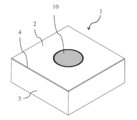
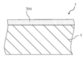
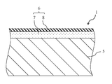
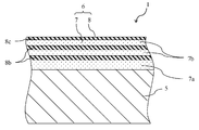
- FIG. 1 It is a perspective view about the cutting insert which is an example of the cutting tool of this embodiment. It is sectional drawing to which the principal part in the cutting insert of FIG. 1 was expanded. It is sectional drawing which shows the other example in the part corresponded in FIG. It is sectional drawing which shows the other example in the part corresponded in FIG.
- a cutting insert (hereinafter simply referred to as an insert) 1 showing an embodiment of a cutting tool includes a first surface 2, a second surface 3 adjacent to the first surface 2, and a first surface, as shown in FIG.
- the ridgeline part 4 is provided in the part which 2 and the 2nd surface 3 cross
- at least a part of the first surface 2 forms a rake surface
- at least a part of the second surface 3 forms a flank surface.
- at least a part of the ridge line portion 4 forms a cutting blade.
- the insert 1 has a through hole 10 that opens to the first surface 2 and penetrates to the surface opposite to the first surface 2.
- the insert 1 includes a base 5 and a DLC layer 6 positioned on the base 5.
- the phrase “located on the substrate 5” means that the DLC layer 6 is positioned on the surface of the substrate 5 before coating.
- the DLC layer 6 may be positioned on at least a part of the substrate 5, but in the present embodiment, the DLC layer 6 is positioned so as to cover almost the entire substrate 5. In other words, the substrate 5 is covered with the DLC layer 6.
- the DLC layer 6 contains diamond-like carbon as a main component.
- “as a main component” means that the DLC layer 6 contains diamond-like carbon having a larger mass than other components.
- the DLC layer 6 in this embodiment has a first region 7 containing argon at a ratio of 0.1% by mass to 1% by mass.
- FIG. 2 shows an example in which the DLC layer 6 includes the first region 7. Since the first region 7 contains argon at a ratio of 0.1% by mass to 1% by mass, it has excellent wear resistance and can suppress welding of the work material. The DLC 6 having the first region 7 is also excellent in wear resistance and can suppress welding of the work material. Therefore, in the insert 1 of this embodiment, the covering effect by the DLC layer 6 is maintained over a long period of time.
- a desirable range of the argon content in the first region 7 is 0.2 mass% to 0.5 mass%.
- the case where the argon content in the first region 7 is 0.1% by mass or more is that argon is irradiated toward the substrate 5 during film formation.
- the oxide layer present on the surface of the substrate 5 is removed, and the surface of the substrate 5 is cleaned.
- region 7 increases, and it is excellent in abrasion resistance. Therefore, if the argon content in the first region 7 is 0.1% by mass or more, the adhesion of the first region 7 to the base 5 is high and the wear resistance is excellent.
- the argon content in the first region 7 is 1% by mass or less, welding of the work material to the insert 1 that occurs when the work material is cut can be reduced.
- the argon content in the film is less than 0.1% by mass.
- membrane will exceed 1 mass%.
- the argon content in the first region 7 can be measured by a WDS (wavelength dispersion type EPMA) analysis method.
- the measurement is performed under the conditions of an acceleration voltage of 15 kV and a probe current of 1 ⁇ 10 ⁇ 7 A.
- the analysis region is desirably measured in a range of 100 ⁇ m or more if possible, but may be measured in a range of less than 100 ⁇ m if the range of 100 ⁇ m or more cannot be obtained.
- a method of measuring the surface of the DLC layer 6 on the polished surface while polishing the surface of the DLC layer 6 by a predetermined thickness There is a method in which the thickness is changed so that the thickness changes, and the measurement is performed at the position of each thickness on the polished surface.
- the first region 7 exists when the argon content measured at one point in the DLC layer 6 is 0.1% by mass to 1% by mass.
- the contents of argon at positions with different thicknesses are respectively measured, and the range in which the argon content is 0.1 mass% to 1 mass% is determined as the first region 7.
- the DLC layer 6 may be constituted by one region only of the first region 7, but may be constituted by a plurality of regions as shown in FIG.
- the DLC layer 6 includes a first region 7 that is in contact with the base 5 and a second region 8 that is located on the first region 7 and has a lower argon content ratio than the first region 7. ing.
- the boundary between the first region 7 and the second region 8 is clear when the DLC layer 6 is viewed in cross section, the first region 7 is referred to as the first layer, and the second region 8 is referred to as the second layer. Also good. Note that the boundary between the first region 7 and the second region 8 is not necessarily clear. When this boundary is not clear, the argon content at a plurality of positions in the DLC layer 6 is measured, and the boundary between the first region 7 and the second region 8 may be evaluated based on these measurement results. .
- the second region 8 has a smaller argon content ratio than the first region 7 and is located on the first region 7.
- the first region 7 has a higher argon content ratio than the second region 8. Therefore, the DLC layer 6 of the insert 1 in the example shown in FIG.
- the welding resistance can be made extremely high.
- the thickness t1 of the first region 7 is 0.1 ⁇ m to 1 ⁇ m and the thickness t2 of the second region 8 is 0.1 ⁇ m to 0.6 ⁇ m, the welding resistance of the DLC layer 6 and Adhesion with the substrate 5 can be improved.
- the ratio (t2 / t1) between the thickness t1 of the first region 7 and the thickness t2 of the second region 8 is 0.2 to 3.0.
- the argon content is measured at a position where the thickness in the DLC layer 6 is different, and the argon content ranges from 0.1 ⁇ m to 1 ⁇ m.
- the upper layer of the first region 7 is defined as the second region.
- the thicknesses of the first region 7 and the second region 8 are the lengths in a direction orthogonal to the interface between the base 5 and the DLC layer 6 (hereinafter sometimes referred to as the surface of the base 5). Means. Note that the thickness direction of the first region 7 and the second region 8 changes depending on the position of the surface of the substrate 5.
- the DLC layer 6 has a configuration in which the thickness of the portion located on the first surface 2 is thicker than the thickness of the portion located on the second surface 3.
- the first surface 2 is a rake face, it is possible to improve the wear resistance against chips flowing on the rake face.
- the DLC layer 6 has a configuration in which the thickness of the portion located in the ridge line portion is thicker than the thickness of the portions located in the first surface 2 and the second surface 3.
- the thickness of the DLC layer 6 located on the cutting edge is large, so that the wear resistance during cutting is increased. be able to.
- the thickness of the DLC layer 6 in the part located in the ridgeline part 4 is 2 etc. of these two surfaces in the cross section orthogonal to the two surfaces (the 1st surface 2 and the 2nd surface 3) which comprise the ridgeline part 4. What is necessary is just to evaluate by the thickness of the DLC layer 6 in the direction along the dividing line.
- the base 5 is made of a hard alloy containing a hard phase and a binder phase.
- the hard alloy include cemented carbides in which the binder phase is made of an iron group metal and the hard phase is made of tungsten carbide, and cermets in which the hard phase is made of titanium carbonitride.
- the iron group metal that is the binder phase is easily oxidized, but according to the present embodiment, the adhesion to the DLC layer 6 is high.
- the content of the binder phase is 5 to 15% by mass, in particular 6 to 10% by mass.
- ceramics may be used as the substrate.
- the coated tool is not limited to the cutting insert 1 of the present embodiment, and can be applied to all cutting tools.
- a drill or end mill having a rod-shaped tool body, a bottom blade at the tip, an outer blade at the tip of the outer periphery, and a chip discharge groove from the tip to the rear adjacent to the bottom blade and the outer blade.
- Reamer router
- it can be applied to sliding members and wear-resistant materials.
- the insert 1 in the example shown in FIG. 4 includes the base 5 and the DLC layer 6 as in the insert 1 shown in FIGS. 1 to 3, but the configuration of the DLC layer 6 is different.
- the example insert 1 shown in FIG. 4 has a plurality of first regions 7 and a plurality of second regions 8.
- the plurality of first regions 7 and second regions 8 are alternately overlapped.
- the DLC layer 6 can be regarded as a laminated body in which the first layer and the second layer are alternately laminated.
- the first region 7 is referred to as a first layer 7, and the second region 8 is referred to as a second layer 8.
- the durability of the DLC layer 6 can be improved. This is because the residual stress applied to the DLC layer 6 can be dispersed by increasing the boundary between the first layer 7 and the second layer 8.
- the DLC layer 6 since the DLC layer 6 includes the plurality of first layers 7 and second layers 8, there is an advantage that the thickness of the DLC layer 6 can be increased.
- the thicknesses of the plurality of first layers 7 may be the same, but when the thickness of the innermost layer 7a closest to the substrate 5 among the plurality of first layers 7 is the thickest, the substrate 5 and the DLC Adhesion (bondability) with the layer 6 can be improved.
- FIG. 4 shows an example in which the innermost layer 7 a is thicker than the intermediate layer 7 b sandwiched between the second layers 8.
- the thicknesses of the plurality of second layers 8 may be the same, but the thickness of the intermediate layer 8b sandwiched between the first regions 7 of the second regions 8 is the farthest away from the substrate 5. When the thickness is greater than the thickness of the outer layer 8 c, the residual stress generated between the first region 7 and the second region 8 can be well relaxed in the second region 8.
- the base 5 is prepared.
- the coated tool is the insert 1
- a sintered body is produced by firing, and then subjected to a polishing process if desired, thereby producing a substrate 1 having a shape corresponding to the insert 1.
- the coated tool is a drill
- the surface of the cylindrical hard alloy is subjected to centerless processing and then subjected to blade processing to produce a drill-shaped base. If desired, polishing is performed on the cutting edge side of the substrate.
- a DLC layer 6 is formed.
- a specific method for forming the DLC layer 6 will be described. First, a target made of graphite is placed in a chamber of a cathodic arc ion plating apparatus, and a sample is set in the apparatus. Next, the inside of the chamber is heated to 100 ° C. to 200 ° C., and argon gas is introduced to perform ion bombardment. Then, once the argon gas is removed, a bias voltage of 30 V to 100 V is applied while flowing the argon gas again at 0.2 Pa to 0.5 Pa, and the plasma is turned on using an argon ion gun.
- argon is irradiated toward the sample, argon ions are implanted, and at the same time, a carbon source is evaporated from the target to form a first region 7 having DLC as a main component on the surface of the substrate 5.
- the film may be formed without using an ion gun. That is, the first region 7 is formed by evaporating the carbon source from the target while applying a bias voltage of 30 V to 100 V while flowing argon gas at 0.2 Pa to 0.5 Pa and in a state where plasma is generated. A second region 8 is formed on the surface of the substrate 5 that has been formed.
- a base body having a drill shape (drill diameter ⁇ 0.105 ⁇ 1.8 mm) was produced through a centerless process and a blade attaching process.
- a graphite target and a base were set in an arc ion plating apparatus, and argon bombarding was performed at 100 ° C. using argon to clean the surface of the target and the base.
- argon bombarding was performed at 100 ° C. using argon to clean the surface of the target and the base.
- Table 1 For some of the samples shown in Table 1, a diamond-like carbon layer was formed on the surface of the substrate under the film forming conditions shown in Table 1 while injecting argon into the sample using an argon ion gun.
- the argon content of the formed DLC layer was measured by WDS (wavelength dispersion type EPMA) analysis.
- WDS wavelength dispersion type EPMA
- the DLC layer formed on the surface of the drill was observed with an SEM, and the thickness of the DLC layer was measured.
- Cutting method Shoulder processed material by machining center: A5052 Cutting speed (feed): 800 m / min Feeding: 0.1 mm / blade cutting: vertical cutting 3 mm, horizontal cutting 5 mm Cutting state: Air blow evaluation method: Check the cutting length and the state of the drill when it becomes impossible to process (described as cutting edge state in the table).
- sample No. 1 having the first region 7 having an argon content of 0.1% by mass to 1% by mass In Nos. 1 to 8, welding to the work material was not large, wear resistance was high, and cutting length was long. In particular, sample No. 1 having a first region 7 having an argon content of 0.1% by mass to 1% by mass and a second region 8 having an argon content ratio of less than 0.1% by mass. In Nos. 1 to 3 and 5, the welding resistance was high and the cutting length was long.
- the thickness of the first region having an argon content of 0.1% by mass to 1% by mass is 0.1 ⁇ m to 1.0 ⁇ m, and the thickness of the second region having an argon content ratio of 0.1% by mass or less. Sample No. 0.1-0.6 ⁇ m. In 1 to 3, 5 and 5, the cutting length was further increased.
- Cutting insert (insert) 2 First side (rake face) 3 Second side (flank) 4 Ridge line (cutting edge) 5 Base 6 DLC Layer 7 First Region (First Layer) 8 Second region (second layer) 10 Through hole
Landscapes
- Chemical & Material Sciences (AREA)
- Engineering & Computer Science (AREA)
- Mechanical Engineering (AREA)
- Organic Chemistry (AREA)
- Materials Engineering (AREA)
- Metallurgy (AREA)
- Chemical Kinetics & Catalysis (AREA)
- Inorganic Chemistry (AREA)
- General Chemical & Material Sciences (AREA)
- Physics & Mathematics (AREA)
- Plasma & Fusion (AREA)
- Cutting Tools, Boring Holders, And Turrets (AREA)
- Drilling Tools (AREA)
- Chemical Vapour Deposition (AREA)
- Physical Vapour Deposition (AREA)
Abstract
Description
次に、上述したDLC層6を有する被覆工具の製造方法について説明する。
切削方法:マシニングセンタによる肩加工
被削材 : A5052
切削速度(送り):800m/min
送り :0.1mm/刃
切り込み:縦切り込み3mm、横切り込み5mm
切削状態:エアーブロー
評価方法:切削長、および加工不能になった時点でのドリルの状態(表中、切刃状態と記載)を確認。

2 第1面(すくい面)
3 第2面(逃げ面)
4 稜線部(切刃)
5 基体
6 DLC層
7 第1領域(第1層)
8 第2領域(第2層)
10 貫通孔
Claims (9)
- 基体と、
該基体の表面に位置し、ダイヤモンドライクカーボンを含有するDLC層とを具備する切削工具であって、
前記DLC層は、0.1質量%~1質量%の比率でアルゴンを含有する第1領域を有している切削工具。 - 前記DLC層は、前記第1領域よりもアルゴンの含有比率が小さく、前記第1領域上に位置する第2領域をさらに有している、請求項1に記載の切削工具。
- 前記第2領域は、アルゴンの含有比率が0.1質量%未満である、請求項2に記載の切削工具。
- 前記第1領域及び前記第2領域が層状であり、前記DLC層の厚み方向に交互に位置している、請求項2または3に記載の切削工具。
- 層状の複数の前記第1領域のうち、前記基体に最も近い最内層の厚みが最も厚い、請求項4に記載の切削工具。
- 層状の複数の前記第2領域のうち、前記第1領域に挟まれた中間層の厚みが、前記基体から最も離れた最外層の厚みよりも厚い、請求項4または5に記載の切削工具。
- 第1面と、
該第1面に隣り合う第2面と、
前記第1面及び前記第2面が交差する部分に稜線部とを有し、
前記DLC層は、前記第1面に位置する部分の厚みが、前記第2面に位置する部分の厚みよりも厚い、請求項1~6のいずれか1つに記載の切削工具。 - 前記DLC層は、前記稜線部に位置する部分の厚みが、前記第1面及び前記第2面に位置する部分の厚みよりも厚い、請求項7に記載の切削工具。
- 前記第1領域の厚みが0.1μm~1μmであり、前記第2領域の厚みが0.1μm~0.6μmである、請求項2~5のいずれか1つに記載の切削工具。
Priority Applications (4)
| Application Number | Priority Date | Filing Date | Title |
|---|---|---|---|
| DE112016002393.6T DE112016002393B4 (de) | 2015-05-28 | 2016-05-30 | Schneidwerkzeug |
| JP2017520826A JP6612864B2 (ja) | 2015-05-28 | 2016-05-30 | 切削工具 |
| CN201680031110.1A CN107614168B (zh) | 2015-05-28 | 2016-05-30 | 切削工具 |
| US15/576,889 US10688565B2 (en) | 2015-05-28 | 2016-05-30 | Cutting tool |
Applications Claiming Priority (2)
| Application Number | Priority Date | Filing Date | Title |
|---|---|---|---|
| JP2015108747 | 2015-05-28 | ||
| JP2015-108747 | 2015-05-28 |
Publications (1)
| Publication Number | Publication Date |
|---|---|
| WO2016190443A1 true WO2016190443A1 (ja) | 2016-12-01 |
Family
ID=57394064
Family Applications (1)
| Application Number | Title | Priority Date | Filing Date |
|---|---|---|---|
| PCT/JP2016/065847 Ceased WO2016190443A1 (ja) | 2015-05-28 | 2016-05-30 | 切削工具 |
Country Status (5)
| Country | Link |
|---|---|
| US (1) | US10688565B2 (ja) |
| JP (1) | JP6612864B2 (ja) |
| CN (1) | CN107614168B (ja) |
| DE (1) | DE112016002393B4 (ja) |
| WO (1) | WO2016190443A1 (ja) |
Cited By (4)
| Publication number | Priority date | Publication date | Assignee | Title |
|---|---|---|---|---|
| WO2021214983A1 (ja) | 2020-04-24 | 2021-10-28 | 住友電工ハードメタル株式会社 | 切削工具 |
| WO2021214985A1 (ja) | 2020-04-24 | 2021-10-28 | 住友電工ハードメタル株式会社 | 切削工具 |
| WO2021214984A1 (ja) | 2020-04-24 | 2021-10-28 | 住友電工ハードメタル株式会社 | 切削工具 |
| WO2022254611A1 (ja) | 2021-06-02 | 2022-12-08 | 住友電工ハードメタル株式会社 | 切削工具 |
Families Citing this family (1)
| Publication number | Priority date | Publication date | Assignee | Title |
|---|---|---|---|---|
| WO2019181792A1 (ja) * | 2018-03-20 | 2019-09-26 | 京セラ株式会社 | インサート及びこれを備えた切削工具 |
Citations (6)
| Publication number | Priority date | Publication date | Assignee | Title |
|---|---|---|---|---|
| JP2003314560A (ja) * | 2002-04-17 | 2003-11-06 | Nsk Ltd | 転動装置 |
| JP2004122263A (ja) * | 2002-09-30 | 2004-04-22 | Sumitomo Electric Ind Ltd | 高精度加工用被覆切削工具 |
| JP2004122264A (ja) * | 2002-09-30 | 2004-04-22 | Sumitomo Electric Ind Ltd | 被覆切削工具 |
| JP2005022073A (ja) * | 2003-06-11 | 2005-01-27 | Sumitomo Electric Hardmetal Corp | Dlc被覆工具 |
| JP2008229755A (ja) * | 2007-03-19 | 2008-10-02 | Ookouchi Kinzoku Kk | Dlc被覆を有する切削工具とその製造方法 |
| WO2013042765A1 (ja) * | 2011-09-22 | 2013-03-28 | Ntn株式会社 | 硬質膜、硬質膜形成体、および転がり軸受 |
Family Cites Families (24)
| Publication number | Priority date | Publication date | Assignee | Title |
|---|---|---|---|---|
| US4490229A (en) * | 1984-07-09 | 1984-12-25 | The United States Of America As Represented By The Administrator Of The National Aeronautics And Space Administration | Deposition of diamondlike carbon films |
| JPH08757B2 (ja) * | 1988-12-26 | 1996-01-10 | 住友電気工業株式会社 | ダイヤモンドおよびその気相合成法 |
| JP2592761B2 (ja) * | 1993-04-28 | 1997-03-19 | 大阪ダイヤモンド工業株式会社 | 回転切削工具及びその製造方法 |
| US5731045A (en) * | 1996-01-26 | 1998-03-24 | Southwest Research Institute | Application of diamond-like carbon coatings to cobalt-cemented tungsten carbide components |
| JP3070957B2 (ja) * | 1995-11-08 | 2000-07-31 | シチズン時計株式会社 | 表面硬化チタン材料およびチタン材料の表面硬化方法 |
| DE10018143C5 (de) * | 2000-04-12 | 2012-09-06 | Oerlikon Trading Ag, Trübbach | DLC-Schichtsystem sowie Verfahren und Vorrichtung zur Herstellung eines derartigen Schichtsystems |
| JP3718664B2 (ja) | 2001-06-13 | 2005-11-24 | 住友電気工業株式会社 | 非晶質カーボン被覆工具およびその製造方法 |
| DE10141696A1 (de) * | 2001-08-25 | 2003-03-13 | Bosch Gmbh Robert | Verfahren zur Erzeugung einer nanostruktuierten Funktionsbeschichtung und damit herstellbare Beschichtung |
| JP2004348627A (ja) * | 2003-05-26 | 2004-12-09 | Toshiba Lsi System Support Kk | マイクロコンピュータシステム |
| EP1522857A1 (en) * | 2003-10-09 | 2005-04-13 | Universiteit Maastricht | Method for identifying a subject at risk of developing heart failure by determining the level of galectin-3 or thrombospondin-2 |
| CN100516286C (zh) * | 2004-12-24 | 2009-07-22 | 鸿富锦精密工业(深圳)有限公司 | 类金刚石薄膜镀膜方法 |
| JP2007196360A (ja) | 2005-12-26 | 2007-08-09 | Kyocera Corp | 寿命センサ回路付き切削工具 |
| EP1884978B1 (en) * | 2006-08-03 | 2011-10-19 | Creepservice S.à.r.l. | Process for the coating of substrates with diamond-like carbon layers |
| CN101212389B (zh) * | 2006-12-30 | 2010-06-23 | 华为技术有限公司 | 一种突发汇聚控制方法及相应的装置、通信设备 |
| US20110104687A1 (en) * | 2008-02-27 | 2011-05-05 | Bruce Grahn | Methods and Kits for Detecting Congenital Stationary Night Blindness and Selecting Different Coat Patterns |
| JP5176621B2 (ja) * | 2008-03-18 | 2013-04-03 | 株式会社タンガロイ | 非晶質炭素被覆工具 |
| US8112859B2 (en) * | 2009-03-24 | 2012-02-14 | Bradford Company | Method of manufacturing custom sized plastic tote having intermediate sleeve |
| JP2010253594A (ja) * | 2009-04-23 | 2010-11-11 | Kyocera Corp | 表面被覆工具 |
| CN102061466B (zh) * | 2009-11-12 | 2014-07-30 | 三菱综合材料株式会社 | 表面包覆切削工具 |
| JP5499650B2 (ja) * | 2009-11-16 | 2014-05-21 | 三菱マテリアル株式会社 | 耐剥離性と耐摩耗性にすぐれたダイヤモンド被覆工具 |
| JP2011104722A (ja) * | 2009-11-18 | 2011-06-02 | Mitsubishi Materials Corp | 耐欠損性、耐溶着性にすぐれたダイヤモンド被覆工具 |
| DE102011076584A1 (de) * | 2011-05-27 | 2012-11-29 | Karnasch Professional Tools GmbH | Schneidwerkzeug mit lasergeschärfter Diamantbeschichtung |
| JP2012125923A (ja) | 2012-03-19 | 2012-07-05 | Okouchi Kinzoku Co Ltd | Dlc被覆を有する切削工具の製造方法 |
| CN102650053B (zh) * | 2012-04-25 | 2014-06-18 | 上海交通大学 | 复杂形状cvd金刚石/类金刚石复合涂层刀具制备方法 |
-
2016
- 2016-05-30 JP JP2017520826A patent/JP6612864B2/ja active Active
- 2016-05-30 US US15/576,889 patent/US10688565B2/en active Active
- 2016-05-30 WO PCT/JP2016/065847 patent/WO2016190443A1/ja not_active Ceased
- 2016-05-30 DE DE112016002393.6T patent/DE112016002393B4/de active Active
- 2016-05-30 CN CN201680031110.1A patent/CN107614168B/zh active Active
Patent Citations (6)
| Publication number | Priority date | Publication date | Assignee | Title |
|---|---|---|---|---|
| JP2003314560A (ja) * | 2002-04-17 | 2003-11-06 | Nsk Ltd | 転動装置 |
| JP2004122263A (ja) * | 2002-09-30 | 2004-04-22 | Sumitomo Electric Ind Ltd | 高精度加工用被覆切削工具 |
| JP2004122264A (ja) * | 2002-09-30 | 2004-04-22 | Sumitomo Electric Ind Ltd | 被覆切削工具 |
| JP2005022073A (ja) * | 2003-06-11 | 2005-01-27 | Sumitomo Electric Hardmetal Corp | Dlc被覆工具 |
| JP2008229755A (ja) * | 2007-03-19 | 2008-10-02 | Ookouchi Kinzoku Kk | Dlc被覆を有する切削工具とその製造方法 |
| WO2013042765A1 (ja) * | 2011-09-22 | 2013-03-28 | Ntn株式会社 | 硬質膜、硬質膜形成体、および転がり軸受 |
Cited By (6)
| Publication number | Priority date | Publication date | Assignee | Title |
|---|---|---|---|---|
| WO2021214983A1 (ja) | 2020-04-24 | 2021-10-28 | 住友電工ハードメタル株式会社 | 切削工具 |
| WO2021214985A1 (ja) | 2020-04-24 | 2021-10-28 | 住友電工ハードメタル株式会社 | 切削工具 |
| WO2021214984A1 (ja) | 2020-04-24 | 2021-10-28 | 住友電工ハードメタル株式会社 | 切削工具 |
| US11992882B2 (en) | 2020-04-24 | 2024-05-28 | Sumitomo Electric Hardmetal Corp. | Cutting tool |
| US12049693B2 (en) | 2020-04-24 | 2024-07-30 | Sumitomo Electric Hardmetal Corp. | Cutting tool |
| WO2022254611A1 (ja) | 2021-06-02 | 2022-12-08 | 住友電工ハードメタル株式会社 | 切削工具 |
Also Published As
| Publication number | Publication date |
|---|---|
| US20180147635A1 (en) | 2018-05-31 |
| JPWO2016190443A1 (ja) | 2018-03-29 |
| CN107614168A (zh) | 2018-01-19 |
| CN107614168B (zh) | 2019-10-25 |
| DE112016002393B4 (de) | 2023-11-02 |
| JP6612864B2 (ja) | 2019-11-27 |
| US10688565B2 (en) | 2020-06-23 |
| DE112016002393T5 (de) | 2018-02-15 |
Similar Documents
| Publication | Publication Date | Title |
|---|---|---|
| JP6612864B2 (ja) | 切削工具 | |
| JP7061603B2 (ja) | 多層硬質皮膜被覆切削工具 | |
| US10384269B2 (en) | Surface-coated cutting tool | |
| JP6015922B2 (ja) | 表面被覆切削工具 | |
| JP2009028800A (ja) | 表面被覆切削工具 | |
| JP2009125832A (ja) | 表面被覆切削工具 | |
| JP2011240438A (ja) | 耐熱性および耐溶着性にすぐれた表面被覆切削工具 | |
| JP5234499B2 (ja) | 高速高送り切削加工で硬質被覆層がすぐれた耐チッピング性を発揮する表面被覆切削工具 | |
| JP2016175161A (ja) | 表面被覆切削工具 | |
| JP5975339B2 (ja) | 表面被覆切削工具 | |
| JP5975214B2 (ja) | 表面被覆切削工具 | |
| JP6206289B2 (ja) | 表面被覆切削工具 | |
| JP5783462B2 (ja) | 表面被覆切削工具 | |
| JP5975338B2 (ja) | 表面被覆切削工具 | |
| JP6471546B2 (ja) | 表面被覆切削工具 | |
| JP4702535B2 (ja) | 高硬度鋼の高速切削加工で硬質被覆層がすぐれた耐摩耗性を発揮する表面被覆高速度工具鋼製切削工具 | |
| JP6206288B2 (ja) | 表面被覆切削工具 | |
| JP2012143851A (ja) | 表面被覆切削工具 | |
| JP2011240436A (ja) | 耐熱性および耐溶着性にすぐれた表面被覆切削工具 | |
| JP2008188737A (ja) | 難削材の重切削加工で硬質被覆層がすぐれた耐チッピング性を発揮する表面被覆切削工具 | |
| JP2009119550A (ja) | 硬質被覆層がすぐれた耐チッピング性を発揮する表面被覆切削工具 | |
| JP5287383B2 (ja) | 高速切削加工で硬質被覆層がすぐれた耐チッピング性と耐摩耗性を発揮する表面被覆切削工具 | |
| JP5796354B2 (ja) | 耐熱性および耐溶着性に優れた表面被覆切削工具 | |
| JP2011173176A (ja) | 耐熱性および耐溶着性にすぐれた表面被覆切削工具 | |
| JP2011173174A (ja) | 耐熱性及び耐溶着性に優れた表面被覆切削工具 |
Legal Events
| Date | Code | Title | Description |
|---|---|---|---|
| 121 | Ep: the epo has been informed by wipo that ep was designated in this application |
Ref document number: 16800147 Country of ref document: EP Kind code of ref document: A1 |
|
| ENP | Entry into the national phase |
Ref document number: 2017520826 Country of ref document: JP Kind code of ref document: A |
|
| WWE | Wipo information: entry into national phase |
Ref document number: 15576889 Country of ref document: US |
|
| WWE | Wipo information: entry into national phase |
Ref document number: 112016002393 Country of ref document: DE |
|
| 122 | Ep: pct application non-entry in european phase |
Ref document number: 16800147 Country of ref document: EP Kind code of ref document: A1 |