WO2016189935A1 - 切削インサートおよび切削工具、並びに切削加工物の製造方法 - Google Patents
切削インサートおよび切削工具、並びに切削加工物の製造方法 Download PDFInfo
- Publication number
- WO2016189935A1 WO2016189935A1 PCT/JP2016/058785 JP2016058785W WO2016189935A1 WO 2016189935 A1 WO2016189935 A1 WO 2016189935A1 JP 2016058785 W JP2016058785 W JP 2016058785W WO 2016189935 A1 WO2016189935 A1 WO 2016189935A1
- Authority
- WO
- WIPO (PCT)
- Prior art keywords
- cutting
- cutting edge
- workpiece
- width
- insert
- Prior art date
Links
Images


Classifications
-
- B—PERFORMING OPERATIONS; TRANSPORTING
- B23—MACHINE TOOLS; METAL-WORKING NOT OTHERWISE PROVIDED FOR
- B23B—TURNING; BORING
- B23B27/00—Tools for turning or boring machines; Tools of a similar kind in general; Accessories therefor
- B23B27/14—Cutting tools of which the bits or tips or cutting inserts are of special material
- B23B27/141—Specially shaped plate-like cutting inserts, i.e. length greater or equal to width, width greater than or equal to thickness
- B23B27/145—Specially shaped plate-like cutting inserts, i.e. length greater or equal to width, width greater than or equal to thickness characterised by having a special shape
- B23B27/146—Means to improve the adhesion between the substrate and the coating
-
- B—PERFORMING OPERATIONS; TRANSPORTING
- B23—MACHINE TOOLS; METAL-WORKING NOT OTHERWISE PROVIDED FOR
- B23B—TURNING; BORING
- B23B27/00—Tools for turning or boring machines; Tools of a similar kind in general; Accessories therefor
- B23B27/14—Cutting tools of which the bits or tips or cutting inserts are of special material
- B23B27/141—Specially shaped plate-like cutting inserts, i.e. length greater or equal to width, width greater than or equal to thickness
- B23B27/145—Specially shaped plate-like cutting inserts, i.e. length greater or equal to width, width greater than or equal to thickness characterised by having a special shape
-
- C—CHEMISTRY; METALLURGY
- C23—COATING METALLIC MATERIAL; COATING MATERIAL WITH METALLIC MATERIAL; CHEMICAL SURFACE TREATMENT; DIFFUSION TREATMENT OF METALLIC MATERIAL; COATING BY VACUUM EVAPORATION, BY SPUTTERING, BY ION IMPLANTATION OR BY CHEMICAL VAPOUR DEPOSITION, IN GENERAL; INHIBITING CORROSION OF METALLIC MATERIAL OR INCRUSTATION IN GENERAL
- C23C—COATING METALLIC MATERIAL; COATING MATERIAL WITH METALLIC MATERIAL; SURFACE TREATMENT OF METALLIC MATERIAL BY DIFFUSION INTO THE SURFACE, BY CHEMICAL CONVERSION OR SUBSTITUTION; COATING BY VACUUM EVAPORATION, BY SPUTTERING, BY ION IMPLANTATION OR BY CHEMICAL VAPOUR DEPOSITION, IN GENERAL
- C23C14/00—Coating by vacuum evaporation, by sputtering or by ion implantation of the coating forming material
- C23C14/06—Coating by vacuum evaporation, by sputtering or by ion implantation of the coating forming material characterised by the coating material
- C23C14/0641—Nitrides
-
- C—CHEMISTRY; METALLURGY
- C23—COATING METALLIC MATERIAL; COATING MATERIAL WITH METALLIC MATERIAL; CHEMICAL SURFACE TREATMENT; DIFFUSION TREATMENT OF METALLIC MATERIAL; COATING BY VACUUM EVAPORATION, BY SPUTTERING, BY ION IMPLANTATION OR BY CHEMICAL VAPOUR DEPOSITION, IN GENERAL; INHIBITING CORROSION OF METALLIC MATERIAL OR INCRUSTATION IN GENERAL
- C23C—COATING METALLIC MATERIAL; COATING MATERIAL WITH METALLIC MATERIAL; SURFACE TREATMENT OF METALLIC MATERIAL BY DIFFUSION INTO THE SURFACE, BY CHEMICAL CONVERSION OR SUBSTITUTION; COATING BY VACUUM EVAPORATION, BY SPUTTERING, BY ION IMPLANTATION OR BY CHEMICAL VAPOUR DEPOSITION, IN GENERAL
- C23C14/00—Coating by vacuum evaporation, by sputtering or by ion implantation of the coating forming material
- C23C14/06—Coating by vacuum evaporation, by sputtering or by ion implantation of the coating forming material characterised by the coating material
- C23C14/0664—Carbonitrides
-
- C—CHEMISTRY; METALLURGY
- C23—COATING METALLIC MATERIAL; COATING MATERIAL WITH METALLIC MATERIAL; CHEMICAL SURFACE TREATMENT; DIFFUSION TREATMENT OF METALLIC MATERIAL; COATING BY VACUUM EVAPORATION, BY SPUTTERING, BY ION IMPLANTATION OR BY CHEMICAL VAPOUR DEPOSITION, IN GENERAL; INHIBITING CORROSION OF METALLIC MATERIAL OR INCRUSTATION IN GENERAL
- C23C—COATING METALLIC MATERIAL; COATING MATERIAL WITH METALLIC MATERIAL; SURFACE TREATMENT OF METALLIC MATERIAL BY DIFFUSION INTO THE SURFACE, BY CHEMICAL CONVERSION OR SUBSTITUTION; COATING BY VACUUM EVAPORATION, BY SPUTTERING, BY ION IMPLANTATION OR BY CHEMICAL VAPOUR DEPOSITION, IN GENERAL
- C23C14/00—Coating by vacuum evaporation, by sputtering or by ion implantation of the coating forming material
- C23C14/06—Coating by vacuum evaporation, by sputtering or by ion implantation of the coating forming material characterised by the coating material
- C23C14/08—Oxides
- C23C14/081—Oxides of aluminium, magnesium or beryllium
-
- C—CHEMISTRY; METALLURGY
- C23—COATING METALLIC MATERIAL; COATING MATERIAL WITH METALLIC MATERIAL; CHEMICAL SURFACE TREATMENT; DIFFUSION TREATMENT OF METALLIC MATERIAL; COATING BY VACUUM EVAPORATION, BY SPUTTERING, BY ION IMPLANTATION OR BY CHEMICAL VAPOUR DEPOSITION, IN GENERAL; INHIBITING CORROSION OF METALLIC MATERIAL OR INCRUSTATION IN GENERAL
- C23C—COATING METALLIC MATERIAL; COATING MATERIAL WITH METALLIC MATERIAL; SURFACE TREATMENT OF METALLIC MATERIAL BY DIFFUSION INTO THE SURFACE, BY CHEMICAL CONVERSION OR SUBSTITUTION; COATING BY VACUUM EVAPORATION, BY SPUTTERING, BY ION IMPLANTATION OR BY CHEMICAL VAPOUR DEPOSITION, IN GENERAL
- C23C28/00—Coating for obtaining at least two superposed coatings either by methods not provided for in a single one of groups C23C2/00 - C23C26/00 or by combinations of methods provided for in subclasses C23C and C25C or C25D
- C23C28/04—Coating for obtaining at least two superposed coatings either by methods not provided for in a single one of groups C23C2/00 - C23C26/00 or by combinations of methods provided for in subclasses C23C and C25C or C25D only coatings of inorganic non-metallic material
- C23C28/044—Coating for obtaining at least two superposed coatings either by methods not provided for in a single one of groups C23C2/00 - C23C26/00 or by combinations of methods provided for in subclasses C23C and C25C or C25D only coatings of inorganic non-metallic material coatings specially adapted for cutting tools or wear applications
-
- C—CHEMISTRY; METALLURGY
- C23—COATING METALLIC MATERIAL; COATING MATERIAL WITH METALLIC MATERIAL; CHEMICAL SURFACE TREATMENT; DIFFUSION TREATMENT OF METALLIC MATERIAL; COATING BY VACUUM EVAPORATION, BY SPUTTERING, BY ION IMPLANTATION OR BY CHEMICAL VAPOUR DEPOSITION, IN GENERAL; INHIBITING CORROSION OF METALLIC MATERIAL OR INCRUSTATION IN GENERAL
- C23C—COATING METALLIC MATERIAL; COATING MATERIAL WITH METALLIC MATERIAL; SURFACE TREATMENT OF METALLIC MATERIAL BY DIFFUSION INTO THE SURFACE, BY CHEMICAL CONVERSION OR SUBSTITUTION; COATING BY VACUUM EVAPORATION, BY SPUTTERING, BY ION IMPLANTATION OR BY CHEMICAL VAPOUR DEPOSITION, IN GENERAL
- C23C30/00—Coating with metallic material characterised only by the composition of the metallic material, i.e. not characterised by the coating process
- C23C30/005—Coating with metallic material characterised only by the composition of the metallic material, i.e. not characterised by the coating process on hard metal substrates
-
- B—PERFORMING OPERATIONS; TRANSPORTING
- B23—MACHINE TOOLS; METAL-WORKING NOT OTHERWISE PROVIDED FOR
- B23B—TURNING; BORING
- B23B2200/00—Details of cutting inserts
- B23B2200/20—Top or side views of the cutting edge
- B23B2200/201—Details of the nose radius and immediately surrounding area
-
- B—PERFORMING OPERATIONS; TRANSPORTING
- B23—MACHINE TOOLS; METAL-WORKING NOT OTHERWISE PROVIDED FOR
- B23B—TURNING; BORING
- B23B2200/00—Details of cutting inserts
- B23B2200/24—Cross section of the cutting edge
- B23B2200/242—Cross section of the cutting edge bevelled or chamfered
-
- B—PERFORMING OPERATIONS; TRANSPORTING
- B23—MACHINE TOOLS; METAL-WORKING NOT OTHERWISE PROVIDED FOR
- B23B—TURNING; BORING
- B23B2200/00—Details of cutting inserts
- B23B2200/28—Angles
-
- B—PERFORMING OPERATIONS; TRANSPORTING
- B23—MACHINE TOOLS; METAL-WORKING NOT OTHERWISE PROVIDED FOR
- B23B—TURNING; BORING
- B23B2200/00—Details of cutting inserts
- B23B2200/36—Other features of cutting inserts not covered by B23B2200/04 - B23B2200/32
- B23B2200/3609—Chamfers
-
- B—PERFORMING OPERATIONS; TRANSPORTING
- B23—MACHINE TOOLS; METAL-WORKING NOT OTHERWISE PROVIDED FOR
- B23B—TURNING; BORING
- B23B2200/00—Details of cutting inserts
- B23B2200/36—Other features of cutting inserts not covered by B23B2200/04 - B23B2200/32
- B23B2200/3645—Lands, i.e. the outer peripheral section of the rake face
- B23B2200/3663—Lands, i.e. the outer peripheral section of the rake face having negative cutting angles
- B23B2200/3672—Lands, i.e. the outer peripheral section of the rake face having negative cutting angles being variable
-
- B—PERFORMING OPERATIONS; TRANSPORTING
- B23—MACHINE TOOLS; METAL-WORKING NOT OTHERWISE PROVIDED FOR
- B23B—TURNING; BORING
- B23B2226/00—Materials of tools or workpieces not comprising a metal
- B23B2226/12—Boron nitride
- B23B2226/125—Boron nitride cubic [CBN]
-
- B—PERFORMING OPERATIONS; TRANSPORTING
- B23—MACHINE TOOLS; METAL-WORKING NOT OTHERWISE PROVIDED FOR
- B23B—TURNING; BORING
- B23B2228/00—Properties of materials of tools or workpieces, materials of tools or workpieces applied in a specific manner
- B23B2228/10—Coatings
Definitions
- the present disclosure relates to a cutting insert, a cutting tool, and a manufacturing method of a cut workpiece, and more particularly, to a cutting insert having a coating layer on a surface of a substrate.
- a cutting insert in which a coating layer is formed on the surface of a substrate such as cemented carbide or cermet to improve wear resistance, slidability, and fracture resistance is widely used. Further, it is known that the cutting edge portion of the cutting insert is formed with a C surface (Chamfer honing) or R honing to increase the strength of the cutting edge.
- Patent Document 1 Japanese Patent Laid-Open No. 10-43912
- a coating layer such as a TiAlN layer is formed on the surface of a substrate made of cemented carbide, and the angle formed with the rake face is 20 to 30 degrees.
- a cutting insert is disclosed in which a chamfer having a width of 0.015 to 0.05 mm as viewed from the rake face side is formed on a cutting edge.
- the cutting insert of the present embodiment includes a base and a coating layer at least partially, A first surface having a plurality of corners; a second surface adjacent to the first surface; a cutting edge located on at least a portion of the ridge line portion of the first surface and the second surface; and the first surface A nose portion located at the corner of the
- the cutting edge has a first cutting edge and a second cutting edge across the nose portion,
- the first cutting edge is located on the coating layer, and has a C-plane with a first width of 5 ⁇ m to 30 ⁇ m in a front view of the first surface and a chamfer angle of 35 ° to 50 °.
- the cutting tool of the present embodiment is one in which the above cutting insert is mounted in an insert pocket provided at the tip of the holder.
- the manufacturing method of the cut workpiece of this embodiment includes a step of rotating a workpiece, a step of bringing the cutting blade of the cutting tool into contact with the rotating workpiece, and cutting the cutting tool into the workpiece. And a step of separating from the object.
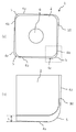
- FIG. 1 It is a schematic perspective view about an example of the cutting insert of this embodiment. It is a fragmentary sectional view of the cutting insert of FIG. (A) is a top view of the cutting insert of FIG. 1, (b) is a principal part enlarged view of (a). (A) is a principal part enlarged view about the other example of the cutting insert of this embodiment, (b) is a side view by the side cutting edge side in the cutting insert of (a), (c) is (a) It is a side view by the side of the front cutting edge in the cutting insert.
- FIG. 6B is a schematic cross-sectional view of part A in the step of bringing the cutting blade of the cutting tool into contact with the workpiece of FIG. 6B.
- a cutting insert (hereinafter referred to as an insert) 1 in FIGS. 1 to 5 has a first surface and a second surface adjacent to the first surface.
- the first surface 2 functions as a rake surface and the second surface 3 functions as a flank surface.
- the rake surface 2 and the flank surface 3 are described.
- at least a part of the ridge line portion between the rake face 2 and the flank face 3 functions as the cutting edge 4.
- the rake face 2 has a plurality of corners, and in the present embodiment, has a substantially polygonal shape.
- a curved nose portion 5 is located at a corner of the rake face 2.
- the cutting edge 4 has a first cutting edge 4a and a second cutting edge 4b with a nose portion 5 interposed therebetween.
- the first cutting edge 4a functions as a front cutting edge
- the second cutting edge 4b functions as a side cutting edge.
- the front cutting edge 4a and the side cutting edge 4b are described.
- the flank 3 has a front flank 3a following the front cutting edge 4a and a side flank 3b following the side cutting edge 4b.
- the boundary between the front cutting edge 4 a and the side cutting edge 4 b is defined as a point farthest from the center of the rake face 2 in the nose portion 5.
- a through hole 6 for inserting a screw is provided at the center of the rake face 2.
- the insert 1 includes a base body 8 and a coating layer 9 provided on the surface of the base body 8 as shown in FIG. At least the front cutting edge 4 a is provided on the surface of the coating layer 9.
- the coating layer 9 was provided in the whole outer surface of the insert 1, The surface of the base
- the front cutting edge 4 a in this embodiment is located on the coating layer 9 and has a C surface 10 between the rake face 2 and the flank face 3.
- the C surface 10 has a chamfer angle ⁇ of 35 ° to 50 °, and a first width L that is the C surface width in the front view of the rake surface 2 is 5 ⁇ m to 30 ⁇ m.
- a weld 7 is generated on the surface of the C surface 10 when the insert 1 comes into contact with the workpiece, and this weld 7 protects the wear of the coating layer 9 from being worn.
- the wear resistance of the insert 1 can be suppressed.
- the insert 1 is mounted in an insert pocket 21 provided at the tip corner of the holder 24.
- the holder 24 has a substantially quadrangular prism shape and has an insert pocket 21 at a position that opens to the side of the tip.
- the holder 24 is made of steel or hardened steel.
- the mounting surface (not shown) of the insert pocket 21 has a screw hole.
- the cutting tool 20 inserts the insert 1 into the insert pocket 21, inserts a screw (not shown) from the rake face 2 side of the insert 1, and screwes the screw into the screw hole of the holder 24, thereby inserting the insert 1. It is attached.
- a cut product is manufactured by the following (i) to (iii).
- the cutting tool 20 is disposed above the prepared workpiece 22. Then, the workpiece is rotated about the rotation axis O in the direction of the arrow r, and the cutting tool 20 is brought close to the workpiece 22 (FIG. 6A).
- the workpiece 22 and the cutting tool 20 need only be relatively close to each other, the workpiece 22 may be brought close to the fixed cutting tool 20.
- the workpiece 22 is cut by bringing the cutting tool 20 closer to the workpiece 22 and bringing the cutting edge 4 of the cutting tool 20 into contact with a predetermined position on the surface of the rotating workpiece 22.
- Process (FIG. 6B) In the cutting process, first, the cutting tool 20 is brought into contact with the insert 1 attached to the cutting tool 20 from a direction perpendicular to the side surface of the workpiece. At that time, the workpiece can be processed by sliding the cutting tool 20 parallel to the rotation axis of the workpiece 22. This is so-called turning. The cutting tool 20 is brought into contact with the workpiece 22 in a state where the cutting tool 20 is tilted to the specified side rake angle ⁇ .
- the contact angle ⁇ of the C surface 10 with the workpiece 22 is determined by the inclination from the direction perpendicular to the finished surface of the workpiece 22, but as shown in the schematic diagram of FIG.
- the contact angle ⁇ with the workpiece 22 is an angle ⁇ + ⁇ obtained by adding the horizontal rake angle ⁇ of the holder 24 and the chamfer angle ⁇ of the C surface 10.
- the force that the C surface 10 receives from the workpiece 22 is a resultant force F of the feed component force and the main component force.
- the angle orthogonal to the C surface 10 (90 ° - ⁇ ) and the resultant force F becomes smaller, a protective film due to the welded material 7 is more likely to be generated, and the C surface 10 is more likely to be cut.
- the contact angle ⁇ with the object 22 is 40 ° to 55 °.
- the chamfer angle ⁇ is 35 ° to 50 °
- generally the side rake angle ⁇ is ⁇ 5 ° to ⁇ 6 °. Therefore, the angle (90 ° ⁇ ) orthogonal to the C plane 10 is It is 40 ° to 56 °.
- the angle formed by the angle (90 ° ⁇ ) orthogonal to the C-plane 10 and the direction of the resultant force F is zero or close to zero. Therefore, it will cut in the form in which the weld 7 exists in the C surface 10, and abrasion of the coating layer 9 which exists in the C surface 10 is suppressed.
- the chamfer angle ⁇ is an angle formed by the C surface 10 with respect to a ground contact surface (not shown) when the insert 1 is placed on the holder 24.
- the first width L is smaller than 5 ⁇ m, the weld 7 is difficult to be generated and the cutting edge 4 is likely to be broken. Conversely, if the first width L is greater than 30 ⁇ m, the cutting resistance increases and the wear progresses faster.
- the second width which is the width of the C face of the side cutting edge 4b (hereinafter referred to as the second C face for identification), is the first width of the front cutting edge 4a. It may be narrower than one width.
- the horizontal cutting edge 4b whose second width is narrower than the first width of the front cutting edge 4a is the first width even if the sharp edge where the second C face is not formed or the second C face is formed. It is narrower than that.
- the chamfer angles of the front cutting edge 4a and the horizontal cutting edge 4b are the same as shown in FIG.
- the width of the cutting edge 4 may gradually become narrower from the front cutting edge 4a through the nose portion 5 toward the side cutting edge 4b.
- This gradually narrowed state is a configuration as shown in FIG.
- good wear resistance and good finished surface can be obtained.
- the finished surface of the work 22 should be smooth and free from fogging. Can do.
- the arithmetic average roughness on the flank 3 is smaller than the arithmetic average roughness on the rake face 2, the weld 7 generated on the C face 10 becomes an appropriate amount, and the finished surface of the work 22 is formed. Can be smooth.
- the arithmetic average roughness on the flank 3 is 0.01 to 0.1 ⁇ m, the finished surface of the workpiece 22 can be smoothed.
- the arithmetic average roughness on the rake face 2 is 0.02 to 0.5 ⁇ m, the amount of the welded material 7 produced is an appropriate amount.
- the arithmetic average roughness on the rake face 2 and the flank face 3 can be adjusted by applying a polishing process from the surface of the coating layer 9 after the coating layer 9 is formed on the substrate 8.
- a polishing process blasting or brushing is suitable.
- the arithmetic average roughness on the rake face 2 and the flank face 3 can be controlled by adjusting the position and orientation of the nozzle that discharges the abrasive grains.
- preferable cutting conditions in the cutting tool 20 of the present embodiment are a cutting speed of 50 m / min to 250 mm / min, a cutting depth of 0.05 mm to 3.0 mm, and a feed rate of 0.05 mm / rev to 0.4 mm / rev. It is. Under this condition, the weld 7 is likely to be generated on the C surface 10 during the cutting process.
- the weld 7 is likely to be generated, and the wear resistance of the coating layer 9 is improved.
- the coating layer 9 is TiC, TiN, TiCN, Al 2 O 3 , TiMN (where M is at least one selected from Group 4, 5, 6 metals, Al, Si excluding Ti) and diamond-like carbon
- M is at least one selected from Group 4, 5, 6 metals, Al, Si excluding Ti
- the surface of the coating layer 9 is smooth and the welded material 7 is likely to be generated.
- the outermost surface of the coating layer 9 is made of TiN or TiMN, a weld is easily generated, and the wear resistance of the coating layer 9 is improved.
- the coating layer 9 may be a single layer or a multilayer of two or more layers.
- the base 8 has a hard phase composed of tungsten carbide (WC) and at least one selected from the group consisting of carbides, nitrides, and carbonitrides of Group 4, 5, and 6 metals of the periodic table as desired.
- Cemented carbide, Ti-based cermet, Si 3 N 4 , Al 2 O 3 , diamond, cubic boron nitride (cBN) bonded with a binder phase composed of an iron group metal such as cobalt (Co) or nickel (Ni) ) And the like can be suitably used.
- the base 8 is preferably made of a cemented carbide or cermet in terms of fracture resistance and wear resistance.
- the substrate 8 may be made of a metal such as carbon steel, high speed steel, or alloy steel.
- a sintered body obtained by molding and firing a predetermined mixed powder is produced.
- the surface of the sintered body is subjected to a polishing process such as a double-ended process or an outer periphery process as desired, and then a C-plane process is applied to the ridge line part.
- a specific method of processing the C surface includes processing with a diamond grindstone.
- the coating layer 9 is formed on the surface of the obtained substrate 8 by physical vapor deposition (PVD) method or chemical vapor deposition (CVD) method. Further, by polishing the surface of the coating layer 9 corresponding to the C surface 10 so that the C surface 10 becomes a smooth surface that can promote the formation of the protective film of the welded material 7, the wear resistance is further improved. Excellent cutting insert.
- PVD physical vapor deposition
- CVD chemical vapor deposition
- a metal cobalt (Co) powder with an average particle size of 1.2 ⁇ m is added to and mixed with tungsten carbide (WC) powder with an average particle size of 1.5 ⁇ m at a ratio of 6% by mass, and a cutting insert shape ( SNGN120408).
- the obtained compact was subjected to a binder removal treatment and fired at 1400 ° C. for 1 hour in a vacuum of 0.5 to 100 Pa to produce a cemented carbide. Further, the produced cemented carbide was processed with a diamond grindstone.
- a TiAlN layer having a thickness of 4 ⁇ m on the C-plane is formed on the cemented carbide by the PVD method.
- 1 to 14 cutting inserts were prepared. For each sample, the chamfer angle on the C surface of the front cutting edge and the width of the C surface in the front view of the rake face, the chamfer angle on the second C surface of the side cutting edge, and the width of the second C surface in the front view of the rake face, The arithmetic average roughness on the rake face and flank face was measured.
- the obtained insert was mounted on a holder having a side rake angle ⁇ of 6 °, and a cutting test was performed in the processing step of FIG. 2 under the following cutting conditions.
- the results are shown in Table 1.
- Cutting method Turning Workpiece: SCM435
- Cutting speed 200 m / min
- Feed 0.2 mm / rev
- Cutting depth 1.5mm
- Cutting state wet (use of cutting oil)
- Evaluation method Cutting distance to flank wear 0.1mm (km)
- sample No. No. 5 has a chamfer angle larger than 50 °. In No. 13, the chamfer angle was smaller than 35 °, and in all cases, no weld was generated on the C surface, and the cutting distance did not increase.
- Sample No. In No. 6 since the width of the C surface viewed from the rake face side was smaller than 5 ⁇ m, chipping occurred on the cutting edge, and the cutting distance was shortened.
- Sample No. In No. 11 the width of the C surface viewed from the rake face side was larger than 30 ⁇ m, so that the cutting resistance increased, the flank wear became significant, and the cutting distance was shortened.
- Sample No. in which the arithmetic average roughness on the flank is smaller than the arithmetic average roughness on the rake face and the arithmetic average roughness on the flank is 0.01 to 0.1 ⁇ m.
- the amount of welded material generated at the front cutting edge was an appropriate amount, the cutting distance was long, and the machined surface roughness was also good.
Landscapes
- Chemical & Material Sciences (AREA)
- Engineering & Computer Science (AREA)
- Mechanical Engineering (AREA)
- Chemical Kinetics & Catalysis (AREA)
- Materials Engineering (AREA)
- Metallurgy (AREA)
- Organic Chemistry (AREA)
- Inorganic Chemistry (AREA)
- Cutting Tools, Boring Holders, And Turrets (AREA)
Abstract
Description
複数の角部を有する第1面と、該第1面に隣り合う第2面と、前記第1面および前記第2面の稜線部の少なくとも一部に位置する切刃と、前記第1面の角部に位置するノーズ部と、を有し、
前記切刃は、前記ノーズ部を挟んで第1切刃と第2切刃とを有し、
前記第1切刃は、前記被覆層上に位置するとともに、前記第1面の正面視における第1幅が5μm~30μmであり、チャンファ角度が35°~50°のC面を有する。
(i)準備された被切削物22の上方に切削工具20を配置する。そして、被切削物を、回転軸Oを中心に矢印r方向に回転させ、切削工具20を被切削物22に近づける(図6A)。ここでは、被切削物22と切削工具20とが相対的に近づけばよいため、固定された切削工具20に被切削物22を近づけてもよい。
切削方法:旋削加工
被切削物:SCM435
切削速度:200m/分
送り :0.2mm/rev
切り込み:1.5mm
切削状態:湿式(切削油使用)
評価方法:逃げ面摩耗0.1mmまでの切削距離(km)

2 すくい面
3 逃げ面
3a 前逃げ面
3b 横逃げ面
4 切刃
4a 前切刃
4b 横切刃
5 ノーズ部
6 貫通孔
7 溶着物
8 基体
9 被覆層
10 C面
20 切削工具
21 インサートポケット
22 被切削物
24 ホルダ
α 横すくい角
β チャンファ角
θ 被切削物との接触角
L 第1幅(すくい面の正面視におけるC面幅)
Claims (11)
- 基体と、少なくとも一部に被覆層を備える切削インサートであって、
複数の角部を有する第1面と、該第1面に隣り合う第2面と、前記第1面および前記第2面の稜線部の少なくとも一部に位置する切刃と、前記第1面の角部に位置するノーズ部と、を有し、
前記切刃は、前記ノーズ部を挟んで第1切刃と第2切刃とを有し、
前記第1切刃は、前記被覆層上に位置するとともに、前記第1面の正面視における第1幅が5μm~30μmであり、チャンファ角度が35°~50°のC面を有する切削インサート。 - 前記第2切刃は、前記第1面の正面視における第2幅が、前記第1幅より狭い請求項1に記載の切削インサート。
- 前記第1面の正面視における前記切刃の幅が、前記第1切刃から前記第2切刃に向かって漸次狭くなる請求項1または2に記載の切削インサート。
- 前記第2面における算術平均粗さが、前記第1面における算術平均粗さよりも小さい請求項1乃至3のいずれかに記載の切削インサート。
- 前記第2面における算術平均粗さが、0.01~0.1μmである請求項4に記載の切削インサート。
- 前記第1面における算術平均粗さが、0.02~0.5μmである請求項4または5に記載の切削インサート。
- 前記被覆層がTiN層、TiMN層およびダイヤモンドライクカーボン層のいずれかを含有する請求項1乃至6のいずれか記載の切削インサート。
- ホルダの先端に設けられたインサートポケットに請求項1乃至7のいずれか記載の切削インサートを装着した切削工具。
- 被切削物を回転させる工程と、回転している前記被切削物に請求項8の切削工具の前記切刃を接触させる工程と、前記切削工具を前記被切削物から離す工程とを備えた切削加工物の製造方法。
- 前記切刃を接触させる工程において、切削速度が50m/分~250mm/分、切り込みが0.05mm~3.0mm、送りが0.05mm/rev~0.4mm/revである請求項9記載の切削加工物の製造方法。
- 前記被切削物が低炭素鋼またはアルミニウム合金鋼である請求項9または10記載の切削加工物の製造方法。
Priority Applications (2)
| Application Number | Priority Date | Filing Date | Title |
|---|---|---|---|
| JP2017520267A JP6659676B2 (ja) | 2015-05-28 | 2016-03-18 | 切削インサートおよび切削工具、並びに切削加工物の製造方法 |
| US15/577,278 US11027338B2 (en) | 2015-05-28 | 2016-03-18 | Cutting insert, cutting tool, and method for manufacturing machined product |
Applications Claiming Priority (2)
| Application Number | Priority Date | Filing Date | Title |
|---|---|---|---|
| JP2015-108748 | 2015-05-28 | ||
| JP2015108748 | 2015-05-28 |
Publications (1)
| Publication Number | Publication Date |
|---|---|
| WO2016189935A1 true WO2016189935A1 (ja) | 2016-12-01 |
Family
ID=57393900
Family Applications (1)
| Application Number | Title | Priority Date | Filing Date |
|---|---|---|---|
| PCT/JP2016/058785 WO2016189935A1 (ja) | 2015-05-28 | 2016-03-18 | 切削インサートおよび切削工具、並びに切削加工物の製造方法 |
Country Status (3)
| Country | Link |
|---|---|
| US (1) | US11027338B2 (ja) |
| JP (1) | JP6659676B2 (ja) |
| WO (1) | WO2016189935A1 (ja) |
Cited By (8)
| Publication number | Priority date | Publication date | Assignee | Title |
|---|---|---|---|---|
| JP6338204B1 (ja) * | 2017-08-29 | 2018-06-06 | 株式会社タンガロイ | 切削インサート及び切削工具 |
| WO2018155644A1 (ja) * | 2017-02-24 | 2018-08-30 | 京セラ株式会社 | 切削インサート及びこれを備えた切削工具 |
| WO2019026698A1 (ja) * | 2017-08-02 | 2019-02-07 | 京セラ株式会社 | 切削インサート、切削工具及び切削加工物の製造方法 |
| WO2019087496A1 (ja) * | 2017-10-31 | 2019-05-09 | 住友電工ハードメタル株式会社 | 切削インサート |
| CN112584955A (zh) * | 2018-07-30 | 2021-03-30 | 京瓷株式会社 | 分切机刀片以及分切机 |
| WO2022085649A1 (ja) * | 2020-10-21 | 2022-04-28 | 京セラ株式会社 | サーメット製インサート及びこれを備えた切削工具 |
| WO2022085647A1 (ja) * | 2020-10-21 | 2022-04-28 | 京セラ株式会社 | サーメット製インサート及びこれを備えた切削工具 |
| JP2022155406A (ja) * | 2021-03-30 | 2022-10-13 | 京セラ株式会社 | インサートおよび切削工具 |
Families Citing this family (4)
| Publication number | Priority date | Publication date | Assignee | Title |
|---|---|---|---|---|
| US11376668B2 (en) * | 2016-09-29 | 2022-07-05 | Sumitomo Electric Hardmetal Corp. | Cutting tool |
| JP7257230B2 (ja) * | 2019-04-12 | 2023-04-13 | 京セラ株式会社 | 切削インサート、切削工具、及び切削加工物の製造方法 |
| JP7001245B2 (ja) * | 2019-08-01 | 2022-01-19 | 住友電工ハードメタル株式会社 | 切削工具の製造方法 |
| WO2023164372A1 (en) * | 2022-02-23 | 2023-08-31 | Us Synthetic Corporation | Cutting tool with pcd inserts, systems incorporating same and related methods |
Citations (5)
| Publication number | Priority date | Publication date | Assignee | Title |
|---|---|---|---|---|
| JPH08155702A (ja) * | 1994-12-07 | 1996-06-18 | Sumitomo Electric Ind Ltd | チップブレーカ付き切削工具及びその製造方法 |
| JP2002192407A (ja) * | 2000-12-26 | 2002-07-10 | Ngk Spark Plug Co Ltd | 切削工具 |
| US20060188347A1 (en) * | 2005-02-22 | 2006-08-24 | Seco Tools Ab | Tool |
| JP2008142890A (ja) * | 2007-12-25 | 2008-06-26 | Kyocera Corp | 切削工具を用いた精密加工方法 |
| WO2011122553A1 (ja) * | 2010-03-29 | 2011-10-06 | 京セラ株式会社 | 切削工具 |
Family Cites Families (4)
| Publication number | Priority date | Publication date | Assignee | Title |
|---|---|---|---|---|
| US5722803A (en) * | 1995-07-14 | 1998-03-03 | Kennametal Inc. | Cutting tool and method of making the cutting tool |
| JPH1043912A (ja) | 1996-07-31 | 1998-02-17 | Ngk Spark Plug Co Ltd | スローアウェイチップ |
| SE530153C2 (sv) * | 2005-02-22 | 2008-03-11 | Seco Tools Ab | Skär för svarvning med ett perifert land av konstant bredd |
| US20130152480A1 (en) * | 2011-12-20 | 2013-06-20 | Smith International, Inc. | Methods for manufacturing polycrystalline ultra-hard constructions and polycrystalline ultra-hard constructions |
-
2016
- 2016-03-18 US US15/577,278 patent/US11027338B2/en active Active
- 2016-03-18 JP JP2017520267A patent/JP6659676B2/ja active Active
- 2016-03-18 WO PCT/JP2016/058785 patent/WO2016189935A1/ja active Application Filing
Patent Citations (5)
| Publication number | Priority date | Publication date | Assignee | Title |
|---|---|---|---|---|
| JPH08155702A (ja) * | 1994-12-07 | 1996-06-18 | Sumitomo Electric Ind Ltd | チップブレーカ付き切削工具及びその製造方法 |
| JP2002192407A (ja) * | 2000-12-26 | 2002-07-10 | Ngk Spark Plug Co Ltd | 切削工具 |
| US20060188347A1 (en) * | 2005-02-22 | 2006-08-24 | Seco Tools Ab | Tool |
| JP2008142890A (ja) * | 2007-12-25 | 2008-06-26 | Kyocera Corp | 切削工具を用いた精密加工方法 |
| WO2011122553A1 (ja) * | 2010-03-29 | 2011-10-06 | 京セラ株式会社 | 切削工具 |
Cited By (20)
| Publication number | Priority date | Publication date | Assignee | Title |
|---|---|---|---|---|
| WO2018155644A1 (ja) * | 2017-02-24 | 2018-08-30 | 京セラ株式会社 | 切削インサート及びこれを備えた切削工具 |
| JPWO2018155644A1 (ja) * | 2017-02-24 | 2019-12-26 | 京セラ株式会社 | 切削インサート及びこれを備えた切削工具 |
| US11420267B2 (en) | 2017-08-02 | 2022-08-23 | Kyocera Corporation | Cutting insert, cutting tool, and method for manufacturing machined product |
| WO2019026698A1 (ja) * | 2017-08-02 | 2019-02-07 | 京セラ株式会社 | 切削インサート、切削工具及び切削加工物の製造方法 |
| WO2019026697A1 (ja) * | 2017-08-02 | 2019-02-07 | 京セラ株式会社 | 切削インサート、切削工具及び切削加工物の製造方法 |
| US12011767B2 (en) | 2017-08-02 | 2024-06-18 | Kyocera Corporation | Cutting insert, cutting tool, and method for manufacturing machined product |
| CN110944777A (zh) * | 2017-08-02 | 2020-03-31 | 京瓷株式会社 | 切削刀片、切削工具以及切削加工物的制造方法 |
| JPWO2019026697A1 (ja) * | 2017-08-02 | 2020-06-18 | 京セラ株式会社 | 切削インサート、切削工具及び切削加工物の製造方法 |
| JPWO2019026698A1 (ja) * | 2017-08-02 | 2020-07-02 | 京セラ株式会社 | 切削インサート、切削工具及び切削加工物の製造方法 |
| JP2019042816A (ja) * | 2017-08-29 | 2019-03-22 | 株式会社タンガロイ | 切削インサート及び切削工具 |
| JP6338204B1 (ja) * | 2017-08-29 | 2018-06-06 | 株式会社タンガロイ | 切削インサート及び切削工具 |
| WO2019087496A1 (ja) * | 2017-10-31 | 2019-05-09 | 住友電工ハードメタル株式会社 | 切削インサート |
| JPWO2019087496A1 (ja) * | 2017-10-31 | 2019-11-14 | 住友電工ハードメタル株式会社 | 切削インサート |
| CN112584955A (zh) * | 2018-07-30 | 2021-03-30 | 京瓷株式会社 | 分切机刀片以及分切机 |
| CN112584955B (zh) * | 2018-07-30 | 2023-10-31 | 京瓷株式会社 | 分切机刀片以及分切机 |
| WO2022085649A1 (ja) * | 2020-10-21 | 2022-04-28 | 京セラ株式会社 | サーメット製インサート及びこれを備えた切削工具 |
| WO2022085647A1 (ja) * | 2020-10-21 | 2022-04-28 | 京セラ株式会社 | サーメット製インサート及びこれを備えた切削工具 |
| JP7483917B2 (ja) | 2020-10-21 | 2024-05-15 | 京セラ株式会社 | サーメット製インサート及びこれを備えた切削工具 |
| JP7483918B2 (ja) | 2020-10-21 | 2024-05-15 | 京セラ株式会社 | サーメット製インサート及びこれを備えた切削工具 |
| JP2022155406A (ja) * | 2021-03-30 | 2022-10-13 | 京セラ株式会社 | インサートおよび切削工具 |
Also Published As
| Publication number | Publication date |
|---|---|
| JPWO2016189935A1 (ja) | 2018-03-29 |
| US11027338B2 (en) | 2021-06-08 |
| US20180161886A1 (en) | 2018-06-14 |
| JP6659676B2 (ja) | 2020-03-04 |
Similar Documents
| Publication | Publication Date | Title |
|---|---|---|
| WO2016189935A1 (ja) | 切削インサートおよび切削工具、並びに切削加工物の製造方法 | |
| JP6593322B2 (ja) | 切削インサート及びその製造方法 | |
| EP1741505B1 (en) | Tool of surface-coated cubic boron nitride sintered compact and process for producing the same | |
| JP4739321B2 (ja) | 刃先交換型切削チップ | |
| JP4783153B2 (ja) | 刃先交換型切削チップ | |
| US6612786B1 (en) | Cutting tool of polycrystalline hard sintered material | |
| JP2003526522A (ja) | 改良された逃げ面の粗さを有する切削インサート及びその製造方法 | |
| JP2001300813A (ja) | ボールエンドミル | |
| US10576555B2 (en) | Cutting insert, cutting tool, and method for manufacturing a cut workpiece | |
| CN110035851B (zh) | 切削刀具 | |
| KR20130004231A (ko) | 절삭 공구 | |
| JP2022065170A (ja) | 切削インサート、切削工具及び切削加工物の製造方法 | |
| JP6556246B2 (ja) | 被覆工具 | |
| JP2003175408A (ja) | 多結晶硬質焼結体スローアウェイチップ | |
| JP2673655B2 (ja) | 木材または木質系複合材加工用の回転切削工具 | |
| JP6847230B2 (ja) | 切削インサート、切削工具及び切削加工物の製造方法 | |
| JP7378716B2 (ja) | エンドミルの製造方法 | |
| JP4878808B2 (ja) | 刃先交換型切削チップ | |
| JP5424911B2 (ja) | 切削工具 | |
| JP4721644B2 (ja) | ミーリング工具およびその検査方法 | |
| JP2020066087A5 (ja) | ||
| JPH04310312A (ja) | エンドミルまたはブレード | |
| JP2002254213A (ja) | チップ並びにスローアウェイチップ及び切削工具 | |
| KR20220110269A (ko) | 피복 공구 | |
| JP2012000699A (ja) | 刃先交換型チップ |
Legal Events
| Date | Code | Title | Description |
|---|---|---|---|
| 121 | Ep: the epo has been informed by wipo that ep was designated in this application |
Ref document number: 16799643 Country of ref document: EP Kind code of ref document: A1 |
|
| ENP | Entry into the national phase |
Ref document number: 2017520267 Country of ref document: JP Kind code of ref document: A |
|
| WWE | Wipo information: entry into national phase |
Ref document number: 15577278 Country of ref document: US |
|
| NENP | Non-entry into the national phase |
Ref country code: DE |
|
| 122 | Ep: pct application non-entry in european phase |
Ref document number: 16799643 Country of ref document: EP Kind code of ref document: A1 |