WO2016174991A1 - 二次電池 - Google Patents
二次電池 Download PDFInfo
- Publication number
- WO2016174991A1 WO2016174991A1 PCT/JP2016/060875 JP2016060875W WO2016174991A1 WO 2016174991 A1 WO2016174991 A1 WO 2016174991A1 JP 2016060875 W JP2016060875 W JP 2016060875W WO 2016174991 A1 WO2016174991 A1 WO 2016174991A1
- Authority
- WO
- WIPO (PCT)
- Prior art keywords
- secondary battery
- separators
- wound
- negative electrode
- separator
- Prior art date
- Legal status (The legal status is an assumption and is not a legal conclusion. Google has not performed a legal analysis and makes no representation as to the accuracy of the status listed.)
- Ceased
Links
Images


Classifications
-
- H—ELECTRICITY
- H01—ELECTRIC ELEMENTS
- H01M—PROCESSES OR MEANS, e.g. BATTERIES, FOR THE DIRECT CONVERSION OF CHEMICAL ENERGY INTO ELECTRICAL ENERGY
- H01M10/00—Secondary cells; Manufacture thereof
- H01M10/05—Accumulators with non-aqueous electrolyte
- H01M10/058—Construction or manufacture
- H01M10/0587—Construction or manufacture of accumulators having only wound construction elements, i.e. wound positive electrodes, wound negative electrodes and wound separators
-
- Y—GENERAL TAGGING OF NEW TECHNOLOGICAL DEVELOPMENTS; GENERAL TAGGING OF CROSS-SECTIONAL TECHNOLOGIES SPANNING OVER SEVERAL SECTIONS OF THE IPC; TECHNICAL SUBJECTS COVERED BY FORMER USPC CROSS-REFERENCE ART COLLECTIONS [XRACs] AND DIGESTS
- Y02—TECHNOLOGIES OR APPLICATIONS FOR MITIGATION OR ADAPTATION AGAINST CLIMATE CHANGE
- Y02E—REDUCTION OF GREENHOUSE GAS [GHG] EMISSIONS, RELATED TO ENERGY GENERATION, TRANSMISSION OR DISTRIBUTION
- Y02E60/00—Enabling technologies; Technologies with a potential or indirect contribution to GHG emissions mitigation
- Y02E60/10—Energy storage using batteries
-
- Y—GENERAL TAGGING OF NEW TECHNOLOGICAL DEVELOPMENTS; GENERAL TAGGING OF CROSS-SECTIONAL TECHNOLOGIES SPANNING OVER SEVERAL SECTIONS OF THE IPC; TECHNICAL SUBJECTS COVERED BY FORMER USPC CROSS-REFERENCE ART COLLECTIONS [XRACs] AND DIGESTS
- Y02—TECHNOLOGIES OR APPLICATIONS FOR MITIGATION OR ADAPTATION AGAINST CLIMATE CHANGE
- Y02P—CLIMATE CHANGE MITIGATION TECHNOLOGIES IN THE PRODUCTION OR PROCESSING OF GOODS
- Y02P70/00—Climate change mitigation technologies in the production process for final industrial or consumer products
- Y02P70/50—Manufacturing or production processes characterised by the final manufactured product
Definitions
- the present invention relates to a secondary battery provided with a wound electrode group.
- secondary batteries with large capacity have been developed as power sources for hybrid electric vehicles and pure electric vehicles, and in particular, prismatic lithium ion secondary batteries with high energy density (Wh / kg) are of interest.
- Wh secondary batteries with large capacity
- Such a secondary battery is configured, for example, by enclosing an electrode group, in which a positive electrode plate and a negative electrode plate are wound with a separator interposed therebetween, together with an electrolytic solution in a battery outer package (for example, Patent Document 1 below). See).
- Patent Document 1 as one of the causes of the internal short circuit of the nonaqueous secondary battery, when the electrode group is wound in a spiral shape, the positional relationship between the electrode plate and the separator is shifted, and the electrode plate is exposed. Is described. In Patent Document 1, the electrode plate and the separator are overlapped and wound around the core, and then wound in a spiral shape. Only the part remains in the core, and therefore, the electrode plate in the vicinity thereof is not covered with the separator, or the central part of the electrode group protrudes from the wound body, and the body does not form the electrode group Etc. are described.
- Patent Document 1 includes a positive electrode plate and a negative electrode plate having different surface friction coefficients as means for solving the above problems, and the positive electrode plate and the negative electrode plate are wound through separators having different friction coefficients on both sides.
- a battery electrode group comprising: a separator having a large friction coefficient surface wound so as to contact a positive electrode plate and a negative electrode plate having a larger surface friction coefficient.
- An electrode group is disclosed. According to Patent Document 1, the above configuration suppresses the electrode plate from being exposed due to the displacement of the separator during the production of the electrode group, and suppresses the dropping of the mixture layer when the electrode group is formed into a flat shape. It is described that it is possible to suppress a short circuit.
- the battery electrode group of Patent Document 1 has a portion where only the separator is wound on the innermost periphery. Since there is neither a positive electrode plate nor a negative electrode plate in this portion, it is impossible to obtain a frictional force due to contact between the separator having a large friction coefficient and the positive electrode plate and the negative electrode plate having the larger surface friction coefficient. Therefore, the battery electrode group of Patent Literature 1 cannot prevent the separator from being displaced at a portion where only the innermost separator is wound when the electrode group is pulled out from the core, for example.
- the present invention has been made in view of the above-described problems, and an object of the present invention is to provide a secondary battery that can prevent the displacement of the innermost separator of the wound electrode group.
- the secondary battery of the present invention is a secondary battery including a wound electrode group in which an electrode is wound with a separator interposed therebetween, and is more than a starting end portion in the winding direction of the electrode.
- a fixing portion for fixing at least a part of the separator wound around the inner periphery is provided.
- the separator of the wound electrode group is displaced by including the fixing portion that fixes at least a part of the separator wound on the inner periphery from the start end in the winding direction of the electrode. Can be prevented.
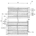
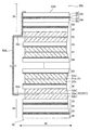
- FIG. 1 is an external perspective view of a secondary battery according to Embodiment 1 of the present invention.
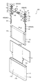
- the disassembled perspective view of the secondary battery shown in FIG. The disassembled perspective view of the winding electrode group of the secondary battery shown in FIG.
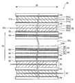
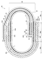
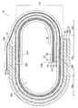
- the expanded sectional view of the wound electrode group which follows the IV-IV line shown in FIG. The expanded sectional view which shows the state by which the wound electrode group shown in FIG. 4 was wound by the winding core.
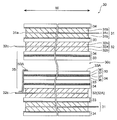
- FIG. 7 is an enlarged cross-sectional view corresponding to FIG. 6 and showing a first modification of the fixing portion according to the first embodiment.
- FIG. 7 is an enlarged cross-sectional view corresponding to FIG.
- FIG. 6 is an enlarged cross-sectional view corresponding to FIG. 4 and showing a third modification of the fixing portion according to the first embodiment.
- the expanded sectional view of the winding electrode group corresponded in FIG. 4 of the secondary battery which concerns on Embodiment 2 of this invention.
- FIG. 1 is an external perspective view of a secondary battery 100 according to Embodiment 1 of the present invention.
- FIG. 2 is an exploded perspective view of the secondary battery 100 shown in FIG.
- the secondary battery 100 of the present embodiment is a rectangular lithium ion secondary battery having a large capacity and high energy density, which is used as a power source for, for example, a hybrid electric vehicle or a pure electric vehicle.
- the secondary battery 100 according to the present embodiment includes at least a part of the separators 33 and 34 wound around the inner periphery of the winding start end 32B of the negative electrode 32 of the wound electrode group 30.
- the greatest feature is that a fixing portion 50 (see FIG. 4) for fixing is provided.
- the secondary battery 100 of the present embodiment is mainly accommodated in a flat rectangular battery container 10, a positive electrode external terminal 20 ⁇ / b> A and a negative electrode external terminal 20 ⁇ / b> B provided outside the battery container 10, and the battery container 10.
- the wound electrode group 30 includes a positive electrode current collector plate 40A and a negative electrode current collector plate 40B that connect the wound electrode group 30 to the positive electrode external terminal 20A and the negative electrode external terminal 20B.
- the positive electrode external terminal 20A and the negative electrode external terminal 20B, the wound electrode group 30, and the positive electrode current collector plate 40A and the negative electrode current collector plate 40B are attached to the battery container 10 by the gasket 1, the insulating plate 2, and the insulating protective film 3. It is electrically insulated.
- the battery container 10, the positive electrode external terminal 20A, and the positive electrode current collector plate 40A can be made of, for example, an aluminum alloy.
- the negative electrode external terminal 20B and the negative electrode current collector plate 40B can be made of, for example, a copper alloy.
- the gasket 1 and the insulating plate 2 can be made of an insulating resin material such as polybutylene terephthalate, polyphenylene sulfide, or perfluoroalkoxy fluororesin.
- the insulating protective film 3 can be manufactured by a sheet of a synthetic resin such as PP (polypropylene) or a plurality of film members.
- the positive electrode side and the negative electrode side for example, the positive electrode external terminal 20A and the negative electrode external terminal 20B, and the positive electrode current collector plate 40A and the negative electrode current collector plate 40B are arranged in the width direction of the secondary battery 100. It has a configuration that is generally in contrast to the centerline at W. Therefore, in the following, regarding the configuration common to the positive electrode side and the negative electrode side, the positive electrode external terminal 20A and the negative electrode external terminal 20B are collectively referred to as the external terminal 20, and the positive electrode current collector plate 40A and the negative electrode current collector plate 40B are collectively illustrated.
- the current collector plate 40 will be described.
- the battery container 10 includes a flat bottomed rectangular tube-shaped battery can 11 having an opening 11 a at the top, and a rectangular flat battery cover 12 that seals the opening 11 a of the battery can 11. .
- the battery can 11 has a generally rectangular bottom surface 11b, a generally rectangular wide side surface 11c and a narrow side surface 11d rising vertically from the bottom surface 11b, and an upper portion is opened to have a generally rectangular opening 11a.
- the battery can 11 is welded and sealed so that the battery lid 12 closes the opening 11a in a state where the wound electrode group 30 is accommodated therein.
- the battery lid 12 has a substantially rectangular upper surface 12a with the width direction W of the secondary battery 100 as the longitudinal direction.
- a positive electrode external terminal 20A and a negative electrode external terminal 20B are provided at one end and the other end of the upper surface 12a of the battery lid 12 in the longitudinal direction.
- the battery lid 12 has through holes 12b through which the columnar connecting portions 22 of the external terminals 20 are inserted at one end and the other end in the longitudinal direction of the upper surface 12a, respectively. It is electrically insulated from the plate 40.
- a gas discharge valve 13 and a liquid injection port 14 are provided at an intermediate portion in the longitudinal direction of the battery lid 12.
- the gas discharge valve 13 is provided integrally with the battery cover 12 by thinning the battery cover 12, for example, and is cleaved and discharges gas when the internal pressure of the battery container 10 exceeds a predetermined value. Then, the internal pressure of the battery container 10 is reduced to ensure the safety of the secondary battery 100.
- the liquid injection port 14 is used to inject an electrolytic solution into the battery container 10, and after the injection of the electrolytic solution, the liquid injection plug 15 is welded and sealed, for example, by laser welding.
- a nonaqueous electrolytic solution in which a lithium salt such as lithium hexafluorophosphate (LiPF 6 ) is dissolved in a carbonic acid ester-based organic solvent such as ethylene carbonate is applied. be able to.
- the external terminal 20 has a welded joint 21 welded to a bus bar or the like, and a connecting part 22 connected to the current collector plate 40.
- the weld joint 21 has a rectangular parallelepiped block shape arranged outside the battery lid 12, the lower surface faces the upper surface of the battery lid 12, and the upper surface is parallel to the upper surface of the battery lid 12 at a predetermined height position. It has a configuration.
- the connection portion 22 protrudes from the lower surface of the weld joint portion 21 in a direction penetrating the battery lid 12 and has a cylindrical shape that can be inserted into the circular through hole 12 b of the battery lid 12.
- the current collector plate 40 is a rectangular plate-like base portion 41 disposed to face the lower surface of the battery lid 12, and is bent at a side end of the base portion 41 and is directed toward the bottom surface along the wide side surface 11 c of the battery can 11.
- a connecting end 42 extending in the direction.
- the base portion 41 of the current collector plate 40 has a through hole 43 through which the connection portion 22 of the external terminal 20 is inserted.
- the connection end portion 42 of the current collector plate 40 is overlapped with the foil exposed portions 31c and 32c at both ends in the winding axis direction of the wound electrode group 30 so as to overlap with each other, for example, by ultrasonic welding or resistance welding. It is joined to the exposed portions 31c and 32c and is electrically connected to the positive electrode 31 and the negative electrode 32 (see FIG. 3) constituting the wound electrode group 30.
- connection portion 22 of the external terminal 20 is sequentially inserted into the through hole 1a of the gasket 1, the through hole 12b of the battery cover 12, the through hole 2a of the insulating plate 2, and the through hole 43 of the base 41 of the current collector plate 40. It crimps so that the front-end
- the wound electrode group 30 is covered with the insulating protective film 3 while being fixed to the battery lid 12 via the current collector plate 40 and the insulating plate 2, and is inserted into the battery can 11 from the opening 11 a of the battery can 11.
- the entire circumference of the battery lid 12 is joined to the entire circumference of the opening 11 a of the battery can 11 by, for example, laser welding, and enclosed in the battery container 10. Thereafter, an electrolytic solution is injected into the battery container 10 through the liquid injection port 14 of the battery lid 12, and a liquid injection plug 15 is joined to the liquid injection port 14 by, for example, laser welding to seal the battery container 10.
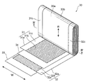
- FIG. 3 is an exploded perspective view of the wound electrode group 30 of the secondary battery 100 shown in FIG.
- FIG. 4 is an enlarged cross-sectional view of the innermost peripheral portion of the wound electrode group 30 along the line IV-IV shown in FIG.
- FIG. 5 is an enlarged cross-sectional view showing a state where the wound electrode group 30 shown in FIG. 4 is wound around the core 60.
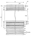
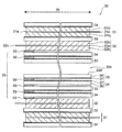
- FIG. 6 is an enlarged cross-sectional view of the wound electrode group 30 along the line VI-VI shown in FIG. 4 and 6 show a state where the core 60 shown in FIG. 5 is removed.
- the wound electrode group 30 is configured by winding the positive electrode 31 and the negative electrode 32 around the separators 33 and 34 wound on the innermost periphery with the separators 33 and 34 interposed therebetween.
- the separators 33 and 34 have a role of insulating between the positive electrode 31 and the negative electrode 32.
- the separators 33, 34 are wound around the core 60 before the positive electrode 31 and the negative electrode 32, and the separators 33, 34 are disposed on the innermost periphery of the wound electrode group 30. 34 is wound over more than one turn. Therefore, in the secondary battery 100 of the present embodiment, the separators 33 and 34 wound around the innermost periphery of the wound electrode group 30 are broadly defined in the winding direction R of the innermost negative electrode 32. The separators 33 and 34 wound around the inner peripheral side from the start end portion 32B are meant. In the present embodiment, the innermost separators 33 and 34 in the broad sense are referred to as leading edge portions 35 of the separators 33 and 34.
- the separator 33 wound around the innermost circumference in a narrow sense.
- the separator 33 wound around the innermost periphery in the narrow sense is referred to as an innermost peripheral portion 33 ⁇ / b> A of the separator 33.
- the innermost peripheral portion 33 ⁇ / b> A of the separator 33 faces the hollow portion 30 c formed at the center of the wound electrode group 30 after the winding core 60 is extracted from the wound electrode group 30.
- the secondary battery 100 of the present embodiment includes at least a part of the separators 33 and 34 wound around the inner periphery of the start end 32B in the winding direction R of the negative electrode 32 of the wound electrode group 30.
- the most characteristic feature is that a fixing portion 50 for fixing is provided.
- the fixing portion 50 fixes the innermost peripheral portion 33A of the separator 33 to the separator 34 on the outer peripheral side, and the separator 34 is further connected to the negative electrode 32 or separator on the outer peripheral side. 33 is fixed. That is, the fixing portion 50 fixes the inner circumferential side separator 33 to the outer circumferential side separator 34 at the leading edge portion 35 of the separators 33 and 34.
- the fixing unit 50 is fixed to the negative electrode 32, and the leading end portion 35 of the separators 33 and 34 is fixed to the negative electrode 32.
- the material of the fixing part 50 is not particularly limited as long as the separators 33 and 34 can be fixed to at least one of the positive electrode 31 and the negative electrode 32.
- an adhesive, an adhesive, or the positive electrode 31 and the negative electrode are used.
- the same material as the binder used for 32 can be used.
- an acrylic adhesive is particularly preferable.
- the fixed portion 50 can be formed by winding the separators 33 and 34 in a state where these materials are applied or arranged on at least one of the front and back surfaces of the separators 33 and 34.
- a heat welding part obtained by melting and solidifying at least a part of the separators 33 and 34 may be used as the fixing part 50.
- the fixing portion 50 is provided between the separators 33 and 34 in the leading end portion 35 of the separators 33 and 34 including the innermost peripheral portion 33A of the separator 33. They are fixed to each other.
- the fixed portion 50 is provided between the separator 34 wound on the outermost side of the leading edge portions 35 of the separators 33, 34 and the negative electrode 32, and includes the innermost peripheral portion 33 ⁇ / b> A of the separator 33.
- the leading end portions 35 of 33 and 34 are fixed to the negative electrode 32.
- the innermost peripheral portion 33A of the separator 33 of the wound electrode group 30 is connected to the negative electrode through the plurality of fixing portions 50 and the separators 33 and 34 of the leading end portion 35. 32 is fixed to the innermost peripheral portion 32A.
- the innermost peripheral portion 32A of the negative electrode 32 means a portion from the winding start end portion 32B of the negative electrode 32 to a round of the winding core 60 or the hollow portion 30c in the winding direction R.
- the fixing portion 50 fixes the leading end portion 35 of the separators 33 and 34 to the negative electrode mixture layer 32b of the innermost peripheral portion 32A of the negative electrode 32.
- the plurality of fixing portions 50 are provided at positions overlapping each other in the stacking direction of the separators 33 and 34, that is, in the thickness direction of the separators 33 and 34.
- the fixing portion 50 is provided on the flat portion 30a of the wound electrode group 30 and is not provided on the curved portion 30b, as shown in FIG. Further, in the secondary battery 100 of the present embodiment, the fixing portion 50 has a width in the width direction W of the separators 33 and 34 orthogonal to the winding direction R of the separators 33 and 34 as shown in FIGS. It is provided over the entire width in the width direction W including the end portion in the direction W.
- start end portion 32B of the negative electrode 32 is disposed outside the leading end portion 35 of the separators 33, 34, and is sandwiched between the separator 34 inside the negative electrode 32 and the separator 33 outside the negative electrode 32.
- the negative electrode 32 is wound around the core 60 shown in FIG. 5 over one or more turns together with the separator 34 on the inner side and the separator 33 on the outer side.
- the leading edge portion 35 of the separators 33, 34 is included in a portion including the start end portion 32 ⁇ / b> B of the negative electrode 32 positioned on the flat portion 30 a of the wound electrode group 30.
- the outermost separator 34 is fixed via a fixing portion 50.
- the fixed portion 50 is provided between the portion including the start end portion 32 ⁇ / b> B of the negative electrode 32 and the separators 33 and 34 of the leading end portion 35 overlapping in the thickness direction of the separators 33 and 34.
- the innermost peripheral portion 33A of the separator 33 includes a plurality of fixed portions 50 and separators 33 of the leading edge portion 35 in a portion including the start end portion 32B of the negative electrode 32. 34 is fixed.
- the start end portion 31B of the positive electrode 31 is sandwiched between the separators 33 and 34 outside the negative electrode 32 wound for more than one turn.
- the positive electrode 31 and the negative electrode 32 are wound around the core 60 over a plurality of circumferences with the separators 33 and 34 interposed therebetween.
- the negative electrode 32 is wound around the outer periphery of the positive electrode 31 via the separator 34 over one round, and the separators 33, 34 are further wound over the outer circumference over the round.
- the terminal portions of the separators 33 and 34 are fixed to the outermost separator 34 of the wound electrode group 30 with an adhesive tape.
- the separators 33 and 34 include a base material 36 and a heat-resistant layer 37 provided on at least one surface of the base material 36.
- the base material 36 is comprised by the porous film which can let electrolyte solution pass, for example.
- a porous film made of a polyolefin resin material can be used as the porous film.
- a resin material for the porous film for example, polypropylene (PP), polyethylene (PE) or the like can be used.
- the porous film may be a single-layer porous film or a laminated porous film in which a plurality of porous films made of the same or different materials are laminated.
- the heat-resistant layer 37 is composed of a filler made of fine particles and a binder made of an inorganic or organic oxide.
- the heat-resistant layer 37 can be manufactured, for example, by applying a resin solution in which a filler and a binder are mixed to at least one surface of a substrate 36 such as a porous film and evaporating the solvent.
- a resin solution in which a filler and a binder are mixed to at least one surface of a substrate 36 such as a porous film and evaporating the solvent.
- the filler for example, fine particles such as alumina (Al 2 O 3 ) and silica (SiO 2 ) can be used, and preferably have heat resistance and insulating properties.
- the filler may be inorganic nitride such as aluminum nitride or fine particles such as boehmite (alumina hydrate), and is not particularly limited as long as it has heat resistance and insulating properties.
- the binder containing an inorganic or organic oxide for example, an acrylic-based, polyolefin-based, fluororesin-based, or SBR-based resin material can be used.
- the positive electrode 31 has a positive electrode foil 31a that is a positive electrode current collector, and a positive electrode mixture layer 31b made of a positive electrode active material mixture applied to both surfaces of the positive electrode foil 31a.
- One side of the positive electrode 31 in the width direction W is a foil exposed portion 31c where the positive electrode mixture layer 31b is not formed and the positive foil 31a is exposed.
- the positive electrode 31 is wound around the core 60 with the foil exposed portion 31 c disposed on the opposite side of the foil exposed portion 32 c of the negative electrode 32 and the axial direction of the core 60, that is, the winding axis direction.
- the positive electrode 31 is formed by, for example, applying a positive electrode active material mixture obtained by adding a conductive material, a binder, and a dispersion solvent to a positive electrode active material and kneading the positive electrode foil 31a on both sides except for one side in the width direction W. It can be produced by drying, pressing and cutting.
- a positive electrode active material mixture obtained by adding a conductive material, a binder, and a dispersion solvent
- a positive electrode active material obtained by adding a conductive material, a binder, and a dispersion solvent
- a positive electrode active material obtained by adding a conductive material, a binder, and a dispersion solvent
- a positive electrode active material obtained by adding a conductive material, a binder, and a dispersion solvent
- the positive electrode foil 31a for example, an aluminum foil having a thickness of about 20 ⁇ m can be used.
- the thickness of the positive electrode mixture layer 31b not including the thickness of the positive electrode foil 31a is
- the positive electrode active material mixture for example, 100 parts by weight of lithium manganate (chemical formula LiMn 2 O 4 ) is used as the positive electrode active material, 10 parts by weight of flaky graphite as the conductive material, and 10% by weight as the binder.
- Part of polyvinylidene fluoride (hereinafter referred to as PVDF) and N-methylpyrrolidone (hereinafter referred to as NMP) can be used as a dispersion solvent.
- the positive electrode active material is not limited to the above-described lithium manganate.
- another lithium manganate having a spinel crystal structure, or a lithium manganese composite oxide partially substituted or doped with a metal element may be used.
- lithium cobalt oxide or lithium titanate having a layered crystal structure, or a lithium-metal composite oxide in which a part thereof is substituted or doped with a metal element may be used.
- the negative electrode 32 has a negative electrode foil 32a that is a negative electrode current collector, and a negative electrode mixture layer 32b made of a negative electrode active material mixture applied to both surfaces of the negative electrode foil 32a.
- One side of the negative electrode 32 in the width direction W is a foil exposed portion 32c where the negative electrode mixture layer 32b is not formed and the negative foil 32a is exposed.
- the negative electrode 32 is wound around the core 60, with the foil exposed portion 32 c thereof arranged on the opposite side of the foil exposed portion 31 c of the positive electrode 31 and the axial direction of the core 60, that is, the winding axis direction.
- the negative electrode 32 is prepared by, for example, applying a negative electrode active material mixture kneaded by adding a binder and a dispersion solvent to the negative electrode active material on both surfaces of the negative electrode foil 32a except for one side in the width direction W, drying, pressing It can be produced by cutting.
- a negative electrode foil 32a for example, a copper foil with a thickness of about 10 ⁇ m can be used.
- the thickness of the negative electrode mixture layer 32b not including the thickness of the negative electrode foil 32a is, for example, about 70 ⁇ m.
- the negative electrode active material mixture for example, 100 parts by weight of amorphous carbon powder as the negative electrode active material, 10 parts by weight of PVDF as the binder, and NMP as the dispersion solvent can be used.
- the negative electrode active material is not limited to the above-mentioned amorphous carbon, and natural graphite capable of inserting and removing lithium ions, various artificial graphite materials, carbonaceous materials such as coke, and compounds such as Si and Sn (for example, , SiO, TiSi 2 or the like), or a composite material thereof.
- the particle shape of the negative electrode active material is not particularly limited, and a particle shape such as a scale shape, a spherical shape, a fiber shape, or a lump shape can be appropriately selected.
- the binder used for the positive electrode mixture layer 31b and the negative electrode mixture layer 32b is not limited to PVDF.
- the binder include polytetrafluoroethylene (PTFE), polyethylene, polystyrene, polybutadiene, butyl rubber, nitrile rubber, styrene butadiene rubber, polysulfide rubber, nitrocellulose, cyanoethyl cellulose, various latexes, acrylonitrile, and vinyl fluoride.
- Polymers such as vinylidene fluoride, propylene fluoride, chloroprene fluoride, and acrylic resins, and mixtures thereof may be used.
- the width of the negative electrode mixture layer 32 b of the negative electrode 32 is wider than the width of the positive electrode mixture layer 31 b of the positive electrode 31 in the axial direction of the winding core 60 of the wound electrode group 30, that is, the winding axis direction.
- a negative electrode 32 is wound around the innermost and outermost circumferences of the wound electrode group 30. Accordingly, the positive electrode mixture layer 31b is sandwiched between the negative electrode mixture layer 32b from the start end portion to the end portion of the positive electrode 31.
- the wound electrode group 30 is manufactured by winding the positive electrode 31 and the negative electrode 32 around the flat core 60 with the separators 33 and 34 interposed therebetween. Accordingly, the wound electrode group 30 includes a flat portion 30a in which the positive electrode 31 and the negative electrode 32 are laminated flat, and a curved portion in which the positive electrode 31 and the negative electrode 32 are bent and laminated on both sides of the flat portion 30a. 30b. That is, the wound electrode group 30 has a pair of semicircular curved portions 30b at both ends of a flat portion 30a as viewed from the winding axis direction.
- the foil exposed portions 31c and 32c of the positive electrode 31 and the negative electrode 32 are respectively bundled by the flat portion 30a of the wound electrode group 30 and joined to the connection end portion 42 of the current collector plate 40 by, for example, ultrasonic pressure welding or resistance welding. Is done.
- the positive electrode external terminal 20A and the negative electrode external terminal 20B are electrically connected to the positive electrode 31 and the negative electrode 32 constituting the wound electrode group 30 via the positive electrode current collector plate 40A and the negative electrode current collector plate 40B, respectively.
- the wound electrode group 30 is inserted into the battery can 11 such that one curved portion 30 b is disposed to face the battery lid 12 and the winding axis direction is along the width direction W of the secondary battery 100.
- the other curved portion 30 b is disposed to face the bottom surface 11 b of the battery can 11.
- the widths of the separators 33 and 34 are wider than the width of the negative electrode mixture layer 32b, but the foil exposed portions 31c and 32c of the positive electrode 31 and the negative electrode 32 are respectively
- the separators 33 and 34 protrude outward in the width direction W from the end portions in the width direction W. Therefore, the separators 33 and 34 do not hinder the foil exposed portions 31c and 32c when bundled and welded.
- the secondary battery 100 having such a configuration is used, for example, as an assembled battery in which a bus bar is welded to the upper surface of the weld joint 21 of the external terminal 20 and a plurality of secondary batteries 100 are connected in series.
- the secondary battery 100 is charged by, for example, storing power supplied from a power supply source such as a generator in the wound electrode group 30 via the external terminal 20 and the current collector plate 40. Further, the secondary battery 100 supplies the power stored in the wound electrode group 30 to a device that consumes power, such as a motor, via the current collector plate 40 and the external terminal 20.
- the positive electrode 31 and the negative electrode 32 are wound around the separators 33 and 34 wound around the innermost periphery with the separators 33 and 34 interposed therebetween.
- a wound electrode group 30 is provided.
- the wound electrode group 30 is manufactured, as shown in FIG. 5, the separators 33 and 34, the positive electrode 31, and the negative electrode 32 are wound around the winding core 60. Extracted from the wound electrode group 30.
- the secondary battery 100 of the present embodiment includes a fixing portion 50 that fixes at least a part of the separators 33 and 34 wound around the inner periphery of the start end portion 32B in the winding direction R of the negative electrode 32. ing. Therefore, when the secondary battery 100 of the present embodiment pulls out the core 60 from the wound electrode group 30, even when a frictional force is generated between the innermost peripheral portion 33A of the separator 33 and the core 60, The fixing portion 50 can prevent the separators 33 and 34 wound around the inner circumference from the start end portion 32B of the negative electrode 32.
- the fixing portion 50 fixes the inner circumferential side separator 33 to the outer circumferential side separator 34 in the leading edge portion 35 of the separators 33 and 34.
- the fixing portion 50 is fixed to the negative electrode 32.
- the fixing portion 50 that fixes the separators 33 and 34 to the negative electrode 32 having higher rigidity than the separators 33 and 34 is provided, the separators 33 and 34 are prevented from being displaced due to the rigidity of the negative electrode 32. it can.
- the innermost peripheral portion 33 ⁇ / b> A of the separator 33 facing the core 60 is used when the core 60 is extracted.
- the friction region RA is likely to be in contact with the winding core 60 and receive a frictional force.
- At least a part of the innermost peripheral portion 33A of the separator 33 that has such a friction region RA and is most likely to shift when the winding core 60 is pulled out is fixed to the negative electrode 32 via the fixing portion 50 and the separators 33 and 34. And fixing the innermost peripheral portion 33A of the separator 33 can be effectively prevented.
- the start end portion 33B of the innermost peripheral portion 33A of the separator 33 is fixed to the negative electrode 32 through the fixing portion 50 and the separators 33 and 34, thereby preventing the displacement of the separators 33 and 34 more reliably. it can.
- the innermost peripheral portion 32A of the negative electrode 32 to which the fixing portion 50 is fixed is an inactive region that does not face the positive electrode 31, and therefore the battery characteristics and the like by the fixing portion 50 are not affected.
- the wound electrode group 30 is formed into a flat shape having a flat portion 30a and a curved portion 30b, and the fixing portion 50 is provided on the flat portion 30a.
- the wound electrode group 30 wound in a flat shape around the core 60 is pressed to be formed into a flatter shape after the winding is completed after the winding is finished. Most of 30 becomes the flat part 30a.
- a sufficient area for fixing the innermost separators 33 and 34 to the negative electrode 32 can be secured. And the displacement of the separators 33 and 34 can be more reliably prevented.
- the fixing portion 50 is provided over the entire width of the separators 33 and 34 in the width direction W. As a result, a sufficient area for fixing the innermost separators 33 and 34 to the negative electrode 32 can be secured, and displacement of the separators 33 and 34 can be prevented more reliably.
- fixed part 50 is the heat welding part which fuse
- a part of separators 33 and 34 can be used as the fixing
- fixed part 50 is an adhesive, it is not necessary to heat or dry the fixing
- the fixing portion 50 is an adhesive, the separators 33 and 34 can be fixed to the negative electrode 32 more firmly than the adhesive.
- the secondary battery 100 of the present embodiment at least a part of the separators 33 and 34 wound around the innermost periphery of the wound electrode group 30 is at least part of the positive electrode 31 and the negative electrode 32.
- the fixing portion 50 that is fixed to one side, it is possible to prevent the separators 33 and 34 on the innermost periphery of the wound electrode group 30 from being displaced. Therefore, according to the secondary battery 100 of the present embodiment, the productivity and yield of the secondary battery 100 can be improved as compared with the conventional case, and an internal short circuit can be prevented more reliably.
- FIG. 7 is an enlarged cross-sectional view corresponding to FIG. 6 illustrating Modification 1 of the fixing portion 50 of the secondary battery 100 of the present embodiment.
- the fixing portion 50 includes the leading end portions 35 of the separators 33 and 34, and the start end portions 33B and 34B of the separators 33 and 34 and the start end portions 33B and 34B in the thickness direction of the separators 33 and 34. It is provided in a region overlapping with 34B.
- the width WR2 in the winding direction R of the fixing portion 50 provided on the front and back surfaces of the separator 34 adjacent to the outermost negative electrode 32 of the leading edge portion 35 of the separators 33 and 34 is the starting end portion of the separators 33 and 34. It is wider than the width WR1 in the winding direction R of the fixing portion 50 provided at 33B, 34B.
- the start ends 33B and 34B of the innermost separators 33 and 34 of the wound electrode group 30 become free ends, the innermost separators 33 and 34 are easily displaced. Accordingly, the start end portions 33B, 34B of the separators 33, 34 are fixed to the negative electrode 32 via the fixing portion 50 and the separators 33, 34, so that the displacement of the innermost separators 33, 34 of the wound electrode group 30 is increased. Can be prevented.
- FIG. 8 is an enlarged cross-sectional view corresponding to FIG. 6 and showing a second modification of the fixing portion 50 of the secondary battery 100 of the present embodiment.
- the fixing portion 50 is provided over one or more rounds in the winding direction R of the separators 33 and 34 from the start end portions 33B and 34B of the separators 33 and 34.
- the area which fixes separator 33, 34 of the innermost periphery with respect to the negative electrode 32 can be expanded more, and it extends over one round or more of winding direction R from start-end part 33B, 34B of separator 33,34. Further, the displacement of the separators 33 and 34 can be prevented more reliably.
- the fixed portion 50 is provided on the curved portion 30 b of the wound electrode group 30.
- FIG. 9 is an enlarged cross-sectional view corresponding to FIG. 4 showing Modification 3 of the fixing portion 50 of the secondary battery 100 of the present embodiment.
- the fixing portion 50 is provided in a part of the width direction W of the separators 33 and 34 orthogonal to the winding direction R of the separators 33 and 34. More specifically, the fixing portion 50 is provided at the end of the separators 33 and 34 in the width direction W.
- the fixing portion 50 in a part of the separators 33 and 34 in the width direction W, the negative electrode 32 having rigidity higher than that of the separators 33 and 34 prevents the separators 33 and 34 from being displaced in the width direction W. Is done. Therefore, the shift in the width direction W of the separators 33 and 34 can be prevented regardless of the direction in which the core 60 is pulled out. Moreover, compared with the case where the fixing
- the fixing portion 50 is provided at the end of the separators 33 and 34 in the width direction W, so that the fixing portion 50 is formed as compared with the case where the fixing portion 50 is provided in the center portion of the separators 33 and 34 in the width direction W. Can be easily.
- the first to third modifications of the fixing unit 50 described above can be applied in appropriate combination with the secondary battery 100 of the first embodiment described above.
- FIG. 10 is an enlarged cross-sectional view of the wound electrode group 30 corresponding to FIG. 4 of the secondary battery according to Embodiment 2 of the present invention.
- the secondary battery of this embodiment is different from the secondary battery 100 described in the first embodiment in that the fixing portion is the adhesive tape 50A. Since the other points of the secondary battery of the present embodiment are the same as those of the secondary battery 100 of the above-described first embodiment, the same portions are denoted by the same reference numerals and description thereof is omitted.
- One end of the adhesive tape 50 ⁇ / b> A is affixed to the surface of the base material 36 facing the core 60 of the innermost peripheral portion 33 ⁇ / b> A of the separator 33, and the other end is wound outside the leading end portion 35 of the separators 33 and 34.
- the negative electrode 32 is affixed to the foil exposed portion 32c of the innermost peripheral portion 32A.
- the adhesive tape 50A has at least a part of the separators 33 and 34 wound around the innermost periphery of the wound electrode group 30, more specifically, at least a part of the innermost peripheral part 33A of the separator 33. It is fixed to the negative electrode 32.
- the adhesive tape 50A is fixed in the width direction W of the innermost circumference 33A of the separator 33.
- One end of the adhesive tape 50 ⁇ / b> A is affixed to the surface of the innermost peripheral portion 33 ⁇ / b> A of the separator 33 that faces the core 60 in a state of projecting from the end portion.
- the positive electrode 31 and the negative electrode 32 are wound around the separators 33 and 34 wound on the innermost periphery with the separators 33 and 34 interposed therebetween.
- the innermost peripheral portion 33A of the separator 33 is fixed to the negative electrode 32 having higher rigidity than the separators 33 and 34, as in the secondary battery of the first embodiment.
- the adhesive that fixes at least a part of the separators 33 and 34 wound around the innermost periphery of the wound electrode group 30 to at least one of the positive electrode 31 and the negative electrode 32.
- the adhesive tape 50A is provided at the end of the separators 33 and 34 in the width direction W. Therefore, the shift in the width direction W of the separators 33 and 34 can be prevented regardless of the direction in which the core 60 is pulled out. Further, by using the adhesive tape 50A, it is possible to fix the separators 33 and 34 to the negative electrode 32 simply by attaching the adhesive tape 50A, and the secondary battery can be easily manufactured.
- the adhesive tape 50A similar to the adhesive tape that fixes the terminal portions of the separators 33 and 34 positioned at the end of winding of the wound electrode group 30 and the outermost separator 34 can be used as a fixing portion. This is also advantageous from the viewpoint of sharing the material of the secondary battery 100.
- the adhesive tape 50A is preferably attached to at least a part of the flat portion 30a of the wound electrode group 30, and more preferably attached to a region where the current collector plate 40 of the foil exposed portion 32c of the negative electrode 32 is not joined. preferable.
- FIG. 11 is an enlarged cross-sectional view corresponding to FIG. 10 showing Modification 1 of the adhesive tape 50A that is a fixing portion of the secondary battery of the present embodiment.
- the adhesive tape 50A is attached to the surface on the base material 36 side, one end of which is opposed to the core 60 of the innermost peripheral portion 33A of the separator 33, and on the outer side of the innermost peripheral portion 32A of the negative electrode 32. It is affixed to the foil exposed portion 31c of the rotated positive electrode 31.
- the adhesive tape 50A has at least a part of the separators 33 and 34 wound around the innermost periphery of the wound electrode group 30, more specifically, at least a part of the innermost peripheral part 33A of the separator 33.
- the positive electrode 31 is fixed.
- the method for applying the adhesive tape 50A to the positive electrode 31 is the same as that for applying the negative electrode 32, but the length of the adhesive tape 50A needs to be slightly longer.
- the foil of the positive electrode 31 is disposed at the end in the direction in which the winding core 60 is pulled out or in the opposite direction. Either the exposed portion 31c or the foil exposed portion 32c of the negative electrode 32 is present. Therefore, the winding tape group structure for winding the wound electrode group 30 forms a fixing portion by the adhesive tape 50A at the end in the winding axis direction of the wound electrode group 30 where the adhesive tape 50A sticking mechanism is easily provided. can do.
- FIG. 12 is an enlarged cross-sectional view corresponding to FIG. 10, illustrating a second modification of the adhesive tape 50 ⁇ / b> A that is a fixing portion of the secondary battery of the present embodiment.
- FIG. 12 only the portion corresponding to the lower portion of the hollow portion 30c of the wound electrode group 30 shown in FIG. 10 is shown enlarged.
- the wound electrode group 30 has a rear collar portion 38 on which the separators 33 and 34 are wound over a plurality of circumferences on the outermost circumference.
- One end of the adhesive tape 50 ⁇ / b> A is affixed to the surface of the innermost peripheral portion 33 ⁇ / b> A of the separator 33 facing the core 60, and the other end is wound inside the rear flange portion 38 of the separators 33 and 34.
- the negative electrode 32 is affixed to the foil exposed portion 32c of the outermost peripheral portion 32C.
- the adhesive tape 50A has at least a part of the separators 33 and 34 wound around the innermost periphery of the wound electrode group 30, more specifically, at least a part of the innermost peripheral part 33A of the separator 33.
- the negative electrode 32 is fixed to the outermost periphery 32C.
- the diameter of the winding core 60 is made smaller than the inner diameter of the wound electrode group 30. Then, a space is formed between the core 60 and the innermost peripheral portion 33A of the separator 33 of the leading end portion 35 of the wound electrode group 30, and the innermost peripheral portion 33A of the separator 33 and the outermost peripheral portion of the negative electrode 32 are formed.
- the foil exposed part 32c of 32C is clamped by the clamp mechanism holding the adhesive tape 50A.
- one end of the adhesive tape 50A is attached to the innermost peripheral portion 33A of the separator 33, and the other end is attached to the foil exposed portion 32c of the outermost peripheral portion 32C of the negative electrode 32, and the wound electrode group is attached by the adhesive tape 50A.
- the separators 33 and 34 wound around the innermost periphery 30 are fixed to the outermost periphery 32 ⁇ / b> C of the negative electrode 32.
- the adhesive tape 50A is preferably attached to at least a part of the flat portion 30a of the wound electrode group 30, and more preferably attached to a region where the current collector plate 40 of the foil exposed portion 32c of the negative electrode 32 is not joined. preferable.
- the secondary battery provided with the adhesive tape 50A of the present modification it is possible to obtain the same effects as those of the secondary battery of Embodiment 2 and Modification 1 described above. Further, according to the secondary battery provided with the adhesive tape 50A of the present modification, the metal foreign matter between the positive electrode 31 of the wound electrode group 30 and the separators 33 and 34 in the actual use environment of the secondary battery. Mixing can be prevented, and voltage drop due to a short circuit phenomenon can be suppressed.
Landscapes
- Engineering & Computer Science (AREA)
- Manufacturing & Machinery (AREA)
- Chemical & Material Sciences (AREA)
- Chemical Kinetics & Catalysis (AREA)
- Electrochemistry (AREA)
- General Chemical & Material Sciences (AREA)
- Secondary Cells (AREA)
Abstract
捲回電極群の電極の捲回方向における始端部よりも内周のセパレータのズレを防止することができる二次電池を提供する。セパレータ33,34を介在させて正負の電極31,32を捲回した捲回電極群30を備えた二次電池であって、電極32の捲回方向Rにおける始端部32Bよりも内周に捲回されたセパレータ33,34の少なくとも一部を固定する固定部50を備える。
Description
本発明は、捲回電極群を備える二次電池に関する。
例えば、ハイブリッド電気自動車や純粋な電気自動車等の動力源として大容量(Wh)の二次電池が開発されており、特に、エネルギー密度(Wh/kg)の高い角形のリチウムイオン二次電池が注目されている。このような二次電池は、例えば、正極板と負極板とをセパレータを介在させて捲回した電極群を電解液とともに電池外装体に封入することによって構成されている(例えば、下記特許文献1を参照)。
特許文献1には、非水二次電池が内部短絡する要因の一つとして、電極群を渦巻き状に捲回する際、電極板とセパレータの位置関係にズレが生じ、電極板が露出することが記載されている。また、特許文献1には、電極板とセパレータを重ねて巻芯に巻きつけることで渦巻き状に捲回した後、巻芯から抜く際、巻芯とセパレータの接触部分において摩擦が大きいために接触部のみが巻芯に残ること、そのため、その付近の電極板がセパレータで覆われなかったり、電極群の中心部分が捲回体からはみ出したりする現象が起こり、電極群として体を成さなくなること等が記載されている。
特許文献1は、前記課題を解決するための手段として、表面の摩擦係数の異なる正極板と負極板とを備え、前記正極板と前記負極板を両面で摩擦係数の異なるセパレータを介して捲回してなる電池用の電極群であって、前記セパレータの摩擦係数の大きい面を正極板と負極板のうち表面の摩擦係数の大きい方と接するように捲回して構成したことを特徴とする電池用電極群を開示している。特許文献1には、前記構成により、電極群の製作時のセパレータのズレによる電極板の露出を抑制し、偏平形状に成形する際の合剤層の脱落を抑制することで、電極群の内部短絡を抑制することが可能である、と記載されている。
特許文献1の図6及び図9を参照すると、特許文献1の電池用電極群は、最内周にセパレータのみが捲回された部分を有している。この部分には、正極板も負極板も存在しないため、セパレータの摩擦係数の大きい面と、正極板と負極板のうち表面の摩擦係数の大きい方との接触による摩擦力を得ることができない。したがって、特許文献1の電池用電極群は、例えば、巻芯から電極群を抜く際に、最内周のセパレータのみが捲回された部分においてセパレータのズレを防止することができない。
本発明は、前記課題に鑑みてなされたものであり、捲回電極群の最内周のセパレータのズレを防止することができる二次電池を提供することを目的とする。
前記目的を達成すべく、本発明の二次電池は、セパレータを介在させて電極を捲回した捲回電極群を備えた二次電池であって、前記電極の捲回方向における始端部よりも内周に捲回された前記セパレータの少なくとも一部を固定する固定部を備えることを特徴とする。
本発明の二次電池によれば、電極の捲回方向における始端部よりも内周に捲回されたセパレータの少なくとも一部を固定する固定部を備えることによって、捲回電極群のセパレータのズレを防止することができる。
以下、図面を参照して本発明の二次電池の実施の形態について説明する。
[実施形態1]
まず、本発明の二次電池の実施形態1について説明する。図1は、本発明の実施形態1に係る二次電池100の外観斜視図である。図2は、図1に示す二次電池100の分解斜視図である。
まず、本発明の二次電池の実施形態1について説明する。図1は、本発明の実施形態1に係る二次電池100の外観斜視図である。図2は、図1に示す二次電池100の分解斜視図である。
本実施形態の二次電池100は、例えば、ハイブリッド電気自動車や純粋な電気自動車等の動力源として用いられる大容量でエネルギー密度の高い角形のリチウムイオン二次電池である。詳細は後述するが、本実施形態の二次電池100は、捲回電極群30の負極電極32の捲回の始端部32Bよりも内周に捲回されたセパレータ33,34の少なくとも一部を固定する固定部50(図4参照)を備えることを最大の特徴としている。
本実施形態の二次電池100は、主に、偏平角形の電池容器10と、該電池容器10の外部に設けられた正極外部端子20A及び負極外部端子20Bと、該電池容器10に収容された捲回電極群30と、該捲回電極群30を正極外部端子20A及び負極外部端子20Bに接続する正極集電板40A及び負極集電板40Bとを有している。正極外部端子20A及び負極外部端子20B、捲回電極群30、並びに正極集電板40A及び負極集電板40Bは、ガスケット1、絶縁板2、及び絶縁保護フィルム3によって、電池容器10に対して電気的に絶縁されている。
電池容器10、正極外部端子20A及び正極集電板40Aは、例えば、アルミニウム合金によって製作することができる。また、負極外部端子20B及び負極集電板40Bは、例えば、銅合金によって製作することができる。また、ガスケット1及び絶縁板2は、例えば、ポリブチレンテレフタレートやポリフェニレンサルファイド、ペルフルオロアルコキシフッ素樹脂等の絶縁性を有する樹脂材料によって製作することができる。絶縁保護フィルム3は、例えばPP(ポリプロピレン)などの合成樹脂製の一枚のシートまたは複数のフィルム部材によって製作することができる。
本実施形態の二次電池100は、正極側と負極側、例えば、正極外部端子20Aと負極外部端子20B、及び、正極集電板40Aと負極集電板40Bが、二次電池100の幅方向Wにおける中心線に概ね対照な構成を有している。したがって、以下では、正極側と負極側において共通する構成については、正極外部端子20A及び負極外部端子20Bを一括して外部端子20と表記し、正極集電板40A及び負極集電板40Bを一括して集電板40と表記して説明する。
電池容器10は、上部に開口部11aを有する偏平な有底角筒状の電池缶11と、該電池缶11の開口部11aを封止する矩形平板状の電池蓋12とを有している。電池缶11は、概ね長方形の底面11bと、該底面11bから垂直に立ち上がる概ね矩形の広側面11c及び狭側面11dを有し、上部が開放されて概ね長方形の開口部11aを有している。電池缶11は、内部に捲回電極群30を収容した状態で、電池蓋12が開口部11aを塞ぐように溶接されて封止される。
電池蓋12は、二次電池100の幅方向Wを長手方向とする概ね長方形の上面12aを有している。電池蓋12の上面12aの長手方向の一端と他端には、正極外部端子20Aと負極外部端子20Bが設けられている。電池蓋12は、上面12aの長手方向の一端と他端に、それぞれ外部端子20の柱状の接続部22を挿通させる貫通孔12bを有し、ガスケット1及び絶縁板2によって外部端子20及び集電板40に対して電気的に絶縁されている。
電池蓋12の長手方向の中間部には、ガス排出弁13と注液口14が設けられている。ガス排出弁13は、例えば、電池蓋12を薄肉化することによって電池蓋12と一体的に設けられ、電池容器10の内部圧力が所定の値を超えて上昇したときに開裂してガスを排出し、電池容器10の内部圧力を低下させて二次電池100の安全性を確保する。注液口14は、電池容器10内に電解液を注入するのに用いられ、電解液の注入後に、注液栓15が、例えばレーザ溶接によって溶接されて封止される。電池容器10内に注入する電解液としては、例えば、エチレンカーボネート等の炭酸エステル系の有機溶媒に6フッ化リン酸リチウム(LiPF6)等のリチウム塩が溶解された非水電解液を適用することができる。
外部端子20は、バスバー等に溶接接合される溶接接合部21と、集電板40に接続される接続部22とを有している。溶接接合部21は、電池蓋12の外側に配置される直方体のブロック形状を有し、下面が電池蓋12の上面に対向し、上面が所定高さ位置で電池蓋12の上面と平行になる構成を有している。接続部22は、溶接接合部21の下面から電池蓋12を貫通する方向に突出し、電池蓋12の円形の貫通孔12bに挿通可能な円柱形状を有している。
集電板40は、電池蓋12の下面に対向して配置される矩形板状の基部41と、基部41の側端で折曲されて電池缶11の広側面11cに沿って底面に向かう方向に延びる接続端部42を有している。集電板40の基部41は、外部端子20の接続部22を挿通させる貫通孔43を有している。集電板40の接続端部42は、捲回電極群30の捲回軸方向の両端部の箔露出部31c,32cに対向して重ね合わされた状態で例えば超音波圧接や抵抗溶接等によって箔露出部31c,32cに接合され、捲回電極群30を構成する正極電極31、負極電極32(図3参照)と電気的に接続される。
外部端子20の接続部22は、ガスケット1の貫通孔1a、電池蓋12の貫通孔12b、絶縁板2の貫通孔2a、及び集電板40の基部41の貫通孔43に順次挿通され、集電板40の基部41の下面すなわち電池蓋12と反対側の面に突出した先端が拡径するようにかしめられる。これにより、外部端子20及び集電板40がガスケット1及び絶縁板2を介して電池蓋12に一体に固定され、捲回電極群30が集電板40及び絶縁板2を介して電池蓋12に固定される。また、外部端子20が集電板40を介して捲回電極群30を構成する正極電極31、負極電極32(図3参照)と電気的に接続される。
捲回電極群30は、集電板40及び絶縁板2を介して電池蓋12に固定された状態で絶縁保護フィルム3によって覆われ、電池缶11の開口部11aから電池缶11内に挿入され、電池蓋12の全周が電池缶11の開口部11aの全周に亘って、例えばレーザ溶接によって接合されて、電池容器10内に封入される。その後、電池蓋12の注液口14を介して電池容器10内に電解液を注入し、注液口14に注液栓15を、例えばレーザ溶接によって接合し、電池容器10を密閉する。
図3は、図2に示す二次電池100の捲回電極群30の分解斜視図である。図4は、図3に示すIV-IV線に沿う捲回電極群30の最内周部分の拡大断面図である。図5は、図4に示す捲回電極群30が巻芯60に捲回された状態を示す拡大断面図である。図6は、図2に示すVI-VI線に沿う捲回電極群30の拡大断面図である。なお、図4及び図6は、図5に示す巻芯60が抜き取られた状態を示している。
捲回電極群30は、最内周に捲回されたセパレータ33,34の周りに、該セパレータ33,34を介在させて正極電極31及び負極電極32を捲回することによって構成される。セパレータ33,34は、正極電極31と負極電極32との間を絶縁する役割を有している。
図4から図6に示すように、セパレータ33,34は、正極電極31及び負極電極32よりも先に巻芯60の周りに捲回され、捲回電極群30の最内周にセパレータ33,34が一周以上に亘って捲回される。したがって、本実施形態の二次電池100において、捲回電極群30の最内周に捲回されたセパレータ33,34とは、広義には、最内周の負極電極32の捲回方向Rの始端部32Bよりも内周側に捲回されたセパレータ33,34を意味する。本実施形態では、この広義の最内周のセパレータ33,34を、セパレータ33,34の先捲部35という。
セパレータ33,34の先捲部35のうち、巻芯60の周りに捲回される際に、巻芯60の外表面に対向する最も内側のセパレータ33の始端部33Bから捲回方向Rに一周するまでの部分が、狭義の最内周に捲回されたセパレータ33である。この狭義の最内周に捲回されたセパレータ33を、セパレータ33の最内周部33Aという。セパレータ33の最内周部33Aは、捲回電極群30から巻芯60が抜き取られた後は、捲回電極群30の中心部に形成される中空部30cに面している。
前記したように、本実施形態の二次電池100は、捲回電極群30の負極電極32の捲回方向Rにおける始端部32Bよりも内周に捲回されたセパレータ33,34の少なくとも一部を固定する固定部50を備えることを最大の特徴としている。また、本実施形態の二次電池100において、固定部50は、セパレータ33の最内周部33Aをその外周側のセパレータ34に固定し、さらにそのセパレータ34をその外周側の負極電極32又はセパレータ33に固定している。すなわち、固定部50は、セパレータ33,34の先捲部35において、内周側のセパレータ33を外周側のセパレータ34に固定している。また、固定部50は、負極電極32に固定され、セパレータ33,34の先捲部35を負極電極32に固定している。
固定部50の材質は、セパレータ33,34を正極電極31及び負極電極32の少なくとも一方に固定できるものであれば特に限定されないが、例えば、粘着剤、接着剤、又は、正極電極31及び負極電極32に用いられる結着材と同様の材料を用いることができる。粘着剤としては、特に、アクリル系粘着剤が好ましい。これらの材料を、例えば、セパレータ33,34の表裏面の少なくとも一方に塗布又は配置した状態で、セパレータ33,34を捲回することで、固定部50を形成することができる。また、セパレータ33,34の少なくとも一部を溶融及び固化させた熱溶着部を固定部50としてもよい。
本実施形態の二次電池100において、固定部50は、セパレータ33の最内周部33Aを含むセパレータ33,34の先捲部35において、セパレータ33,34間に設けられ、セパレータ33,34を相互に固定している。また、固定部50は、セパレータ33,34の先捲部35のうち、最も外側に捲回されたセパレータ34と負極電極32との間に設けられ、セパレータ33の最内周部33Aを含むセパレータ33,34の先捲部35を負極電極32に固定している。
すなわち、本実施形態の二次電池100は、捲回電極群30のセパレータ33の最内周部33Aが、複数の固定部50と先捲部35のセパレータ33,34とを介して、負極電極32の最内周部32Aに固定されている。ここで、負極電極32の最内周部32Aとは、負極電極32の捲回の始端部32Bから捲回方向Rに巻芯60又は中空部30cを一周するまでの部分を意味する。より詳細には、固定部50は、負極電極32の最内周部32Aの負極合剤層32bに対してセパレータ33,34の先捲部35を固定している。また、複数の固定部50は、セパレータ33,34の積層方向、すなわちセパレータ33,34の厚さ方向に互いに重なる位置に設けられている。
また、本実施形態の二次電池100において、固定部50は、図6に示すように、捲回電極群30の平坦部30aに設けられ、湾曲部30bには設けられていない。また、本実施形態の二次電池100において、固定部50は、図4及び図5に示すように、セパレータ33,34の捲回方向Rに直交するセパレータ33,34の幅方向Wにおいて、幅方向Wの端部を含む幅方向Wの全幅に亘って設けられている。
さらに、セパレータ33,34の先捲部35の外側に負極電極32の始端部32Bが配置され、負極電極32の内側のセパレータ34と、負極電極32の外側のセパレータ33との間に挟み込まれる。負極電極32は、その内側のセパレータ34及びその外側のセパレータ33とともに、図5に示す巻芯60の周りに一周以上に亘って捲回される。
本実施形態の二次電池100では、図6に示すように、捲回電極群30の平坦部30aに位置する負極電極32の始端部32Bを含む部分に、セパレータ33,34の先捲部35の最外周のセパレータ34が固定部50を介して固定されている。また、固定部50は、負極電極32の始端部32Bを含む部分とセパレータ33,34の厚さ方向に重なる先捲部35のセパレータ33,34間に設けられている。これにより、捲回電極群30の平坦部30aにおいて、セパレータ33の最内周部33Aが、負極電極32の始端部32Bを含む部分に、複数の固定部50と先捲部35のセパレータ33,34とを介して固定されている。
さらに、一周以上に亘って捲回された負極電極32の外側のセパレータ33,34との間に、図5に示すように、正極電極31の始端部31Bが挟み込まれる。そして、正極電極31及び負極電極32は、セパレータ33,34を介在させて、巻芯60の周りに複数周に亘って捲回される。捲回電極群30の最外周部分では、正極電極31の外側にセパレータ34を介して負極電極32が一周以上に亘って捲回され、さらにその外側にセパレータ33,34が一周以上に亘って捲回される。セパレータ33,34の終端部は、粘着テープによって捲回電極群30の最外周のセパレータ34に固定される。
セパレータ33,34は、基材36と、基材36の少なくとも一方の面に設けられた耐熱層37と、を備えている。基材36は、例えば、電解液を通すことが可能な多孔質フィルムによって構成されている。多孔質フィルムとしては、例えば、ポリオレフィン系の樹脂材料からなる多孔質フィルムを用いることができる。多孔質フィルムの樹脂材料としては、例えば、ポリプロピレン(PP)、ポリエチレン(PE)等を用いることができる。
また、多孔質フィルムは、単層多孔質フィルムであってもよく、同一または異種材料からなる複数の多孔質フィルムが積層された積層多孔質フィルムであってもよい。
また、多孔質フィルムは、単層多孔質フィルムであってもよく、同一または異種材料からなる複数の多孔質フィルムが積層された積層多孔質フィルムであってもよい。
耐熱層37は、微粒子からなるフィラーと、無機又は有機酸化物からなるバインダとによって構成されている。耐熱層37は、例えば、フィラーおよびバインダを混合した樹脂溶液を多孔質フィルム等の基材36の少なくとも一方の面に塗布し、溶剤を気化させることによって製作することができる。フィラーとしては、例えば、アルミナ(Al2O3)、シ
リカ(SiO2)等の微粒子を用いることができ、耐熱性および絶縁性を有していることが好ましい。また、フィラーは、窒化アルミニウム等の無機窒化物や、ベーマイト(アルミナ水和物)等の微粒子でも良く、耐熱性及び絶縁性を有する微粒子であれば特に制限はない。無機又は有機酸化物を含むバインダとしては、例えば、アクリル系、ポリオレフィン系、フッ素樹脂系、SBR系の樹脂材料等を用いることができる。
リカ(SiO2)等の微粒子を用いることができ、耐熱性および絶縁性を有していることが好ましい。また、フィラーは、窒化アルミニウム等の無機窒化物や、ベーマイト(アルミナ水和物)等の微粒子でも良く、耐熱性及び絶縁性を有する微粒子であれば特に制限はない。無機又は有機酸化物を含むバインダとしては、例えば、アクリル系、ポリオレフィン系、フッ素樹脂系、SBR系の樹脂材料等を用いることができる。
正極電極31は、正極集電体である正極箔31aと、正極箔31aの両面に塗布された正極活物質合剤からなる正極合剤層31bとを有している。正極電極31の幅方向Wの一側は、正極合剤層31bが形成されず、正極箔31aが露出した箔露出部31cとされている。正極電極31は、箔露出部31cが負極電極32の箔露出部32cと巻芯60の軸方向すなわち捲回軸方向の反対側に配置されて巻芯60の周りに捲回される。
正極電極31は、例えば、正極活物質に導電材、結着剤及び分散溶媒を添加して混練した正極活物質合剤を、正極箔31aの両面に幅方向Wの一側を除いて塗布し、乾燥、プレス、裁断することによって製作することができる。正極箔31aとしては、例えば、厚さ約20μmのアルミニウム箔を用いることができる。正極箔31aの厚みを含まない正極合剤層31bの厚さは、例えば、約90μmである。
正極活物質合剤の材料としては、例えば、正極活物質として100重量部のマンガン酸リチウム(化学式LiMn2O4)を、導電材として10重量部の鱗片状黒鉛を、結着剤として10重量部のポリフッ化ビニリデン(以下、PVDFという。)を、分散溶媒としてN-メチルピロリドン(以下、NMPという。)を、それぞれ用いることができる。正極活物質は、前記したマンガン酸リチウムに限定されず、例えば、スピネル結晶構造を有する他のマンガン酸リチウム、一部を金属元素で置換又はドープしたリチウムマンガン複合酸化物を用いてもよい。また、正極活物質として、層状結晶構造を有するコバルト酸リチウムやチタン酸リチウム、及びこれらの一部を金属元素で置換又はドープしたリチウム-金属複合酸化物を用いてもよい。
負極電極32は、負極集電体である負極箔32aと、負極箔32aの両面に塗布された負極活物質合剤からなる負極合剤層32bとを有している。負極電極32の幅方向Wの一側は、負極合剤層32bが形成されず、負極箔32aが露出した箔露出部32cとされている。負極電極32は、その箔露出部32cが正極電極31の箔露出部31cと巻芯60の軸方向すなわち捲回軸方向の反対側に配置されて、巻芯60の周りに捲回される。
負極電極32は、例えば、負極活物質に結着剤及び分散溶媒を添加して混練した負極活物質合剤を、幅方向Wの一側を除く負極箔32aの両面に塗布し、乾燥、プレス、裁断することによって製作することができる。負極箔32aとしては、例えば、厚さ約10μmの銅箔を用いることができる。負極箔32aの厚みを含まない負極合剤層32bの厚さは、例えば、約70μmである。
負極活物質合剤の材料としては、例えば、負極活物質として100重量部の非晶質炭素粉末を、結着剤として10重量部のPVDFを、分散溶媒としてNMPをそれぞれ用いることができる。負極活物質は、前記した非晶質炭素に限定されず、リチウムイオンを挿入、脱離可能な天然黒鉛や、人造の各種黒鉛材、コークスなどの炭素質材料やSiやSnなどの化合物(例えば、SiO、TiSi2等)、又はそれらの複合材料を用いてもよい。
負極活物質の粒子形状についても特に限定されず、鱗片状、球状、繊維状又は塊状等の粒子形状を適宜選択することができる。
負極活物質の粒子形状についても特に限定されず、鱗片状、球状、繊維状又は塊状等の粒子形状を適宜選択することができる。
なお、前記した正極合剤層31b及び負極合剤層32bに用いる結着材は、PVDFに限定されない。前記した結着材として、例えば、ポリテトラフルオロエチレン(PTFE)、ポリエチレン、ポリスチレン、ポリブタジエン、ブチルゴム、ニトリルゴム、スチレンブタジエンゴム、多硫化ゴム、ニトロセルロース、シアノエチルセルロース、各種ラテックス、アクリロニトリル、フッ化ビニル、フッ化ビニリデン、フッ化プロピレン、フッ化クロロプレン、アクリル系樹脂などの重合体及びこれらの混合体などを用いてもよい。
捲回電極群30の巻芯60の軸方向すなわち捲回軸方向において、負極電極32の負極合剤層32bの幅は、正極電極31の正極合剤層31bの幅よりも広くなっている。また、捲回電極群30の最内周と最外周には負極電極32が捲回されている。これにより、正極電極31の始端部から終端部まで、正極合剤層31bが負極合剤層32bの間に挟まれている。
前述のように、捲回電極群30は、偏平形状の巻芯60の周りにセパレータ33,34を介在させて正極電極31及び負極電極32を捲回することによって製作される。これにより、捲回電極群30は、正極電極31及び負極電極32が平坦に積層された平坦部30aと、平坦部30aの両側で正極電極31及び負極電極32が湾曲して積層された湾曲部30bとを有する偏平形状に成形される。すなわち、捲回電極群30は、捲回軸方向から見て、平坦な平坦部30aの両端に一対の半円形状の湾曲部30bが形成されている。
正極電極31及び負極電極32の箔露出部31c,32cはそれぞれ捲回電極群30の平坦部30aで束ねられ、例えば超音波圧接、抵抗溶接等によって、集電板40の接続端部42に接合される。これにより、正極外部端子20A及び負極外部端子20Bが、それぞれ正極集電板40A及び負極集電板40Bを介して、捲回電極群30を構成する正極電極31及び負極電極32とそれぞれ電気的に接続される。これにより、捲回電極群30は、一方の湾曲部30bが電池蓋12に対向して配置され、捲回軸方向が二次電池100の幅方向Wに沿うように電池缶11内に挿入され、他方の湾曲部30bが電池缶11の底面11bに対向して配置される。
なお、捲回電極群30の捲回軸方向において、セパレータ33,34の幅は負極合剤層32bの幅よりも広いが、正極電極31及び負極電極32の箔露出部31c,32cは、それぞれセパレータ33,34の幅方向W端部よりも幅方向W外側に突出している。したがって、セパレータ33,34は、箔露出部31c,32cを束ねて溶接する際の支障にはならない。
このような構成を有する二次電池100は、例えば、外部端子20の溶接接合部21の上面にバスバーが溶接され、複数の二次電池100を直列に接続した組電池として用いられる。二次電池100は、例えば、発電機等の電力供給源から供給された電力を、外部端子20及び集電板40を介して捲回電極群30に蓄積することで充電される。また、二次電池100は、捲回電極群30に蓄積した電力を、集電板40及び外部端子20を介して、例えば、モーター等の電力を消費する装置に供給する。
以下、本実施形態の二次電池100の作用について説明する。
本実施形態の二次電池100は、前述のように、最内周に捲回されたセパレータ33,34の周りに該セパレータ33,34を介在させて正極電極31及び負極電極32を捲回した捲回電極群30を備えている。この捲回電極群30の製作時に、図5に示すように、セパレータ33,34、正極電極31及び負極電極32は、巻芯60の周りに捲回され、捲回終了後に、巻芯60は捲回電極群30から抜き取られる。
前記特許文献1に記載された従来の電池用電極群では、最内周のセパレータのみが捲回された部分に、正極板も負極板も存在せず、正極板又は負極板との接触による摩擦力を得ることができない。また、電極群の最内周のセパレータのみが捲回された部分は、固定されておらず、始端部が自由端になっている。そのため、前記従来の電池用電極群は、巻芯を抜く際に、最内周のセパレータのみが捲回された部分においてセパレータにズレが生じ、内部短絡する要因になったり、電極群としての体を成さなくなったりする虞がある。
これに対し、本実施形態の二次電池100は、負極電極32の捲回方向Rにおける始端部32Bよりも内周に捲回されたセパレータ33,34の少なくとも一部固定する固定部50を備えている。そのため、本実施形態の二次電池100は、捲回電極群30から巻芯60を抜き取る際に、セパレータ33の最内周部33Aと巻芯60との間に摩擦力が生じた場合でも、固定部50によって負極電極32の始端部32Bよりも内周に捲回されたセパレータ33,34のズレを防止できる。
また、本実施形態の二次電池100は、セパレータ33,34の先捲部35において、固定部50が、内周側のセパレータ33を外周側のセパレータ34に固定している。これにより、固定部50によって負極電極32の始端部32Bよりも内周に捲回されたセパレータ33,34のズレを防止でき、セパレータ33の最内周部33Aのズレを防止することができる。また、本実施形態の二次電池100は、固定部50が負極電極32に固定されている。このように、セパレータ33,34と比較して剛性の高い負極電極32に対してセパレータ33,34を固定する固定部50を有することで、負極電極32の剛性によってセパレータ33,34のズレを防止できる。
特に、捲回電極群30の最内周に捲回されたセパレータ33,34の先捲部35のうち、巻芯60に面するセパレータ33の最内周部33Aは、巻芯60を抜き取る際に巻芯60に接して摩擦力を受ける可能性のある摩擦領域RAとなる。このような摩擦領域RAを有し、巻芯60を抜き取る際に最もズレやすいセパレータ33の最内周部33Aの少なくとも一部を、固定部50及びセパレータ33,34を介して負極電極32に対して固定することで、セパレータ33の最内周部33Aのズレを効果的に防止することができる。
さらに、本実施形態の二次電池100は、固定部50が、図6に示すように、最内周に捲回されたセパレータ33,34の先捲部35の捲回方向Rにおける始端部33B,34Bに設けられている。セパレータ33,34の始端部33B,34Bは、特にずれが生じやすいことから、セパレータ33,34の始端部33B,34Bに固定部50を設けることによって、より効果的にセパレータ33,34のズレを防止することができる。特に、セパレータ33の最内周部33Aの始端部33Bを、固定部50及びセパレータ33,34を介して負極電極32に固定することで、より確実にセパレータ33,34のズレを防止することができる。なお、固定部50が固定される負極電極32の最内周部32Aは、正極電極31と対向していない不活領域であることから、固定部50による電池特性などへの影響はない。
また、本実施形態の二次電池100において、捲回電極群30は、平坦部30aと湾曲部30bとを有する偏平形状に成形され、固定部50は、平坦部30aに設けられている。巻芯60の周りに偏平形状に捲回された捲回電極群30は、捲回が終了して巻芯60が抜き取られた後、プレスされてより偏平な形状に成形され、捲回電極群30の大部分が平坦部30aとなる。このように、捲回電極群30の大部分を占める平坦部30aに固定部50を設けることで、最内周のセパレータ33,34を負極電極32に対して固定する面積を十分に確保することができ、セパレータ33,34のズレをより確実に防止することができる。
また、本実施形態の二次電池100において、固定部50は、セパレータ33,34の幅方向Wの全幅に亘って設けられる。これにより、最内周のセパレータ33,34を負極電極32に対して固定する面積を十分に確保することができ、セパレータ33,34のズレをより確実に防止することができる。
また、固定部50が、セパレータ33,34を溶融及び固化させた熱溶着部である場合には、新たな部材を追加することなく、セパレータ33,34の一部を固定部50にすることができる。また、固定部50が、粘着剤である場合には、固定部50を加熱したり乾燥させたりする必要がなく、二次電池100の製造に要する時間を短縮し、生産性を向上させることが可能になる。また、固定部50が、接着剤である場合には、セパレータ33,34を負極電極32に対して粘着剤よりも強固に固定することが可能になる。
以上説明したように、本実施形態の二次電池100によれば、捲回電極群30の最内周に捲回されたセパレータ33,34の少なくとも一部を正極電極31及び負極電極32の少なくとも一方に固定する固定部50を備えることによって、捲回電極群30の最内周のセパレータ33,34のズレを防止することができる。したがって、本実施形態の二次電池100によれば、従来よりも二次電池100の生産性及び歩留りを向上させ、内部短絡をより確実に防止することができる。
以下、本実施形態の二次電池100の固定部50の変形例1から変形例3について、図7から図9を用いて説明する。
(変形例1)
図7は、本実施形態の二次電池100の固定部50の変形例1を示す図6に相当する拡大断面図である。本変形例において、固定部50は、セパレータ33,34の先捲部35のうち、セパレータ33,34の厚さ方向において、セパレータ33,34の始端部33B,34B、及び、該始端部33B,34Bと重なる領域に設けられている。なお、セパレータ33,34の先捲部35の最も外側の負極電極32に隣接するセパレータ34の表裏面に設けられた固定部50の捲回方向Rの幅WR2は、セパレータ33,34の始端部33B,34Bに設けられた固定部50の捲回方向Rの幅WR1よりも広くなっている。
図7は、本実施形態の二次電池100の固定部50の変形例1を示す図6に相当する拡大断面図である。本変形例において、固定部50は、セパレータ33,34の先捲部35のうち、セパレータ33,34の厚さ方向において、セパレータ33,34の始端部33B,34B、及び、該始端部33B,34Bと重なる領域に設けられている。なお、セパレータ33,34の先捲部35の最も外側の負極電極32に隣接するセパレータ34の表裏面に設けられた固定部50の捲回方向Rの幅WR2は、セパレータ33,34の始端部33B,34Bに設けられた固定部50の捲回方向Rの幅WR1よりも広くなっている。
前述のように、捲回電極群30の最内周のセパレータ33,34の始端部33B,34Bが自由端になると、最内周のセパレータ33,34がズレやすくなる。したがって、セパレータ33,34の始端部33B,34Bを、固定部50及びセパレータ33,34を介して負極電極32に固定することで、捲回電極群30の最内周のセパレータ33,34のズレを防止することができる。
(変形例2)
図8は、本実施形態の二次電池100の固定部50の変形例2を示す図6に相当する拡大断面図である。本変形例において、固定部50は、セパレータ33,34の始端部33B,34Bからセパレータ33,34の捲回方向Rに一周以上に亘って設けられている。これにより、最内周のセパレータ33,34を負極電極32に対して固定する面積をより拡大することができ、セパレータ33,34の始端部33B,34Bから捲回方向Rの一周以上に亘って、セパレータ33,34のズレをより確実に防止することができる。また、本変形例において、固定部50は、捲回電極群30の湾曲部30bに設けられている。これにより、捲回電極群30の平坦部30aと比較して締め付けの強い湾曲部30bのセパレータ33,34のズレを確実に防止することができる。
図8は、本実施形態の二次電池100の固定部50の変形例2を示す図6に相当する拡大断面図である。本変形例において、固定部50は、セパレータ33,34の始端部33B,34Bからセパレータ33,34の捲回方向Rに一周以上に亘って設けられている。これにより、最内周のセパレータ33,34を負極電極32に対して固定する面積をより拡大することができ、セパレータ33,34の始端部33B,34Bから捲回方向Rの一周以上に亘って、セパレータ33,34のズレをより確実に防止することができる。また、本変形例において、固定部50は、捲回電極群30の湾曲部30bに設けられている。これにより、捲回電極群30の平坦部30aと比較して締め付けの強い湾曲部30bのセパレータ33,34のズレを確実に防止することができる。
(変形例3)
図9は、本実施形態の二次電池100の固定部50の変形例3を示す図4に相当する拡大断面図である。本変形例において、固定部50は、セパレータ33,34の捲回方向Rに直交するセパレータ33,34の幅方向Wの一部に設けられている。より具体的には、固定部50は、セパレータ33,34の幅方向Wの端部に設けられている。
図9は、本実施形態の二次電池100の固定部50の変形例3を示す図4に相当する拡大断面図である。本変形例において、固定部50は、セパレータ33,34の捲回方向Rに直交するセパレータ33,34の幅方向Wの一部に設けられている。より具体的には、固定部50は、セパレータ33,34の幅方向Wの端部に設けられている。
このように、固定部50をセパレータ33,34の幅方向Wの一部に設けることで、セパレータ33,34よりも剛性の高い負極電極32によって、セパレータ33,34の幅方向Wのズレが防止される。したがって、巻芯60を抜き取る方向によらずセパレータ33,34の幅方向Wのズレを防止することができる。また、固定部50をセパレータ33,34の幅方向Wの全幅に亘って設ける場合と比較して、固定部50の材料の使用量を削減することができ、コスト的に有利である。固定部50は、セパレータ33,34の幅方向Wの端部に設けることで、固定部50をセパレータ33,34の幅方向Wの中央部に設ける場合と比較して、固定部50の形成を容易にすることができる。
以上の固定部50の変形例1から変形例3は、前述の実施形態1の二次電池100に適宜組み合わせて適用することができる。
[実施形態2]
次に、本発明の二次電池の実施形態2について、図1から図3を援用し、図10を用いて説明する。図10は、本発明の実施形態2に係る二次電池の図4に相当する捲回電極群30の拡大断面図である。
次に、本発明の二次電池の実施形態2について、図1から図3を援用し、図10を用いて説明する。図10は、本発明の実施形態2に係る二次電池の図4に相当する捲回電極群30の拡大断面図である。
本実施形態の二次電池は、固定部が粘着テープ50Aである点で、前述の実施形態1で説明した二次電池100と異なっている。本実施形態の二次電池のその他の点は、前述の実施形態1の二次電池100と同一であるため、同一の部分には同一の符号を付して説明を省略する。
粘着テープ50Aは、一端がセパレータ33の最内周部33Aの巻芯60に対向する基材36側の表面に貼付され、他端がセパレータ33,34の先捲部35の外側に捲回された負極電極32の最内周部32Aの箔露出部32cに貼付されている。これにより、粘着テープ50Aは、捲回電極群30の最内周に捲回されたセパレータ33,34の少なくとも一部、より詳細には、セパレータ33の最内周部33Aの少なくとも一部を、負極電極32に固定している。
粘着テープ50Aによって捲回電極群30の最内周に捲回されたセパレータ33,34を負極電極32に固定するには、まず、粘着テープ50Aをセパレータ33の最内周部33Aの幅方向Wの端部から突出させた状態で、粘着テープ50Aの一端をセパレータ33の最内周部33Aの巻芯60に対向する面に貼付する。この状態で、前述の実施形態1と同様に、最内周に捲回されたセパレータ33,34の周りに、該セパレータ33,34を介在させて正極電極31及び負極電極32を捲回する。これにより、セパレータ33の最内周部33Aの幅方向Wの端部から突出した粘着テープ50Aの他端が、負極電極32の箔露出部32cに貼付される。
本実施形態の二次電池によれば、前述の実施形態1の二次電池と同様に、セパレータ33,34よりも剛性の高い負極電極32にセパレータ33の最内周部33Aを固定することで、前述の実施形態1の二次電池100と同様の効果を得ることができる。すなわち、本実施形態の二次電池によれば、捲回電極群30の最内周に捲回されたセパレータ33,34の少なくとも一部を正極電極31及び負極電極32の少なくとも一方に固定する粘着テープ50Aを備えることによって、捲回電極群30の最内周のセパレータ33,34のズレを防止することができる。
また、粘着テープ50Aは、セパレータ33,34の幅方向Wの端部に設けられている。したがって、巻芯60を抜き取る方向によらずセパレータ33,34の幅方向Wのズレを防止することができる。また、粘着テープ50Aを用いることで、粘着テープ50Aを貼り付けるだけで負極電極32に対してセパレータ33,34を固定することができ、二次電池の製造を容易にすることができる。
また、捲回電極群30の捲回の捲き終わりに位置するセパレータ33,34の終端部と最外周のセパレータ34を固定する粘着テープと同様の粘着テープ50Aを固定部として流用することが可能となり、二次電池100の材料の共通化の観点からも有益である。なお、粘着テープ50Aは、捲回電極群30の平坦部30aの少なくとも一部に貼付することが好ましく、負極電極32の箔露出部32cの集電板40が接合されない領域に貼付することがより好ましい。
以下、本実施形態の二次電池の固定部である粘着テープ50Aの変形例1及び変形例2について、図11及び図12を用いて説明する。
(変形例1)
図11は、本実施形態の二次電池の固定部である粘着テープ50Aの変形例1を示す図10に相当する拡大断面図である。本変形例において、粘着テープ50Aは、一端がセパレータ33の最内周部33Aの巻芯60に対向する基材36側の表面に貼付され、負極電極32の最内周部32Aの外側に捲回された正極電極31の箔露出部31cに貼付されている。これにより、粘着テープ50Aは、捲回電極群30の最内周に捲回されたセパレータ33,34の少なくとも一部、より詳細には、セパレータ33の最内周部33Aの少なくとも一部を、正極電極31に固定している。
図11は、本実施形態の二次電池の固定部である粘着テープ50Aの変形例1を示す図10に相当する拡大断面図である。本変形例において、粘着テープ50Aは、一端がセパレータ33の最内周部33Aの巻芯60に対向する基材36側の表面に貼付され、負極電極32の最内周部32Aの外側に捲回された正極電極31の箔露出部31cに貼付されている。これにより、粘着テープ50Aは、捲回電極群30の最内周に捲回されたセパレータ33,34の少なくとも一部、より詳細には、セパレータ33の最内周部33Aの少なくとも一部を、正極電極31に固定している。
粘着テープ50Aを正極電極31に貼付する方法は、前述の負極電極32に貼付する場合と同様であるが、粘着テープ50Aの長さをやや長くする必要がある。また、捲回電極群30から巻芯60を抜き取る方向が捲回軸方向の何れの方向になっても、巻芯60を抜き取る方向の端部又はその反対方向の端部に正極電極31の箔露出部31c又は負極電極32の箔露出部32cの何れかが存在する。したがって、捲回電極群30を捲回する捲回機の構造上、粘着テープ50Aの貼付機構を設けやすい捲回電極群30の捲回軸方向の端部において、粘着テープ50Aによる固定部を形成することができる。
(変形例2)
図12は、本実施形態の二次電池の固定部である粘着テープ50Aの変形例2を示す図10に相当する拡大断面図である。なお、図12においては、図10に示す捲回電極群30の中空部30cの下方側の部分に対応する部分のみを拡大して示している。本変形例において、捲回電極群30は、最外周にセパレータ33,34が複数周に亘って捲回された後捲部38を有している。
図12は、本実施形態の二次電池の固定部である粘着テープ50Aの変形例2を示す図10に相当する拡大断面図である。なお、図12においては、図10に示す捲回電極群30の中空部30cの下方側の部分に対応する部分のみを拡大して示している。本変形例において、捲回電極群30は、最外周にセパレータ33,34が複数周に亘って捲回された後捲部38を有している。
粘着テープ50Aは、一端がセパレータ33の最内周部33Aの巻芯60に対向する基材36側の表面に貼付され、他端がセパレータ33,34の後捲部38の内側に捲回された負極電極32の最外周部32Cの箔露出部32cに貼付されている。これにより、粘着テープ50Aは、捲回電極群30の最内周に捲回されたセパレータ33,34の少なくとも一部、より詳細には、セパレータ33の最内周部33Aの少なくとも一部を、負極電極32の最外周部32Cに固定している。
粘着テープ50Aによって捲回電極群30の最内周に捲回されたセパレータ33,34を負極電極32の最外周部32Cに固定するには、まず、捲回電極群30の捲回終了後に、巻芯60の径を捲回電極群30の内径よりも縮小させる。そして、巻芯60と捲回電極群30の先捲部35のセパレータ33の最内周部33Aとの間に空間を形成し、セパレータ33の最内周部33Aと負極電極32の最外周部32Cの箔露出部32cとを、粘着テープ50Aを保持したクランプ機構によって挟持する。
これにより、粘着テープ50Aは、一端がセパレータ33の最内周部33Aに貼付され、他端が負極電極32の最外周部32Cの箔露出部32cに貼付され、粘着テープ50Aによって捲回電極群30の最内周に捲回されたセパレータ33,34が負極電極32の最外周部32Cに固定される。なお、粘着テープ50Aは、捲回電極群30の平坦部30aの少なくとも一部に貼付することが好ましく、負極電極32の箔露出部32cの集電板40が接合されない領域に貼付することがより好ましい。
本変形例の粘着テープ50Aを備えた二次電池によれば、前述の実施形態2及びその変形例1の二次電池と同様の効果を得ることができる。また、本変形例の粘着テープ50Aを備えた二次電池によれば、二次電池の実使用環境化における捲回電極群30の正極電極31とセパレータ33,34との間への金属異物の混入を防ぐことが可能となり、短絡現象による電圧低下を抑制することができる。
以上、図面を用いて本発明の実施の形態を詳述してきたが、具体的な構成はこの実施形態に限定されるものではなく、本発明の要旨を逸脱しない範囲における設計変更等があっても、それらは本発明に含まれるものである。
30 捲回電極群
30a 平坦部
30b 湾曲部
31 正極電極(電極)
32 負極電極(電極)
33 セパレータ
33B 始端部
34 セパレータ
34B 始端部
50 固定部
50A 粘着テープ(固定部)
100 二次電池
R 捲回方向
W 幅方向
30a 平坦部
30b 湾曲部
31 正極電極(電極)
32 負極電極(電極)
33 セパレータ
33B 始端部
34 セパレータ
34B 始端部
50 固定部
50A 粘着テープ(固定部)
100 二次電池
R 捲回方向
W 幅方向
Claims (13)
- セパレータを介在させて電極を捲回した捲回電極群を備えた二次電池であって、
前記電極の捲回方向における始端部よりも内周に捲回された前記セパレータの少なくとも一部を固定する固定部を備えることを特徴とする二次電池。 - 前記固定部は、前記電極に固定されることを特徴とする請求項1に記載の二次電池。
- 前記捲回電極群は、前記電極が平坦に積層された平坦部と、該平坦部の両側で前記電極が湾曲して積層された湾曲部とを有する偏平形状に成形され、
前記固定部は、前記平坦部に設けられることを特徴とする請求項2に記載の二次電池。 - 前記固定部は、前記セパレータの捲回方向における始端部に設けられることを特徴とする請求項3に記載の二次電池。
- 前記固定部は、前記セパレータの前記始端部から前記捲回方向に一周以上に亘って設けられることを特徴とする請求項4に記載の二次電池。
- 前記固定部は、前記湾曲部に設けられることを特徴とする請求項3に記載の二次電池。
- 前記固定部は、前記セパレータの捲回方向に直交する前記セパレータの幅方向の少なくとも一部に設けられることを特徴とする請求項1から請求項6のいずれか一項に記載の二次電池。
- 前記固定部は、前記幅方向の全幅に亘って設けられることを特徴とする請求項7に記載の二次電池。
- 前記固定部は、前記幅方向の端部に設けられることを特徴とする請求項7に記載の二次電池。
- 前記固定部は、粘着テープであることを特徴とする請求項9に記載の二次電池。
- 前記固定部は、前記セパレータを溶融及び固化させた熱溶着部であることを特徴とする請求項7に記載の二次電池。
- 前記固定部は、粘着剤であることを特徴とする請求項7に記載の二次電池。
- 前記固定部は、接着剤であることを特徴とする請求項7に記載の二次電池。
Priority Applications (1)
| Application Number | Priority Date | Filing Date | Title |
|---|---|---|---|
| JP2017515450A JP6563008B2 (ja) | 2015-04-28 | 2016-04-01 | 二次電池 |
Applications Claiming Priority (2)
| Application Number | Priority Date | Filing Date | Title |
|---|---|---|---|
| JP2015-091827 | 2015-04-28 | ||
| JP2015091827 | 2015-04-28 |
Publications (1)
| Publication Number | Publication Date |
|---|---|
| WO2016174991A1 true WO2016174991A1 (ja) | 2016-11-03 |
Family
ID=57199614
Family Applications (1)
| Application Number | Title | Priority Date | Filing Date |
|---|---|---|---|
| PCT/JP2016/060875 Ceased WO2016174991A1 (ja) | 2015-04-28 | 2016-04-01 | 二次電池 |
Country Status (2)
| Country | Link |
|---|---|
| JP (1) | JP6563008B2 (ja) |
| WO (1) | WO2016174991A1 (ja) |
Cited By (5)
| Publication number | Priority date | Publication date | Assignee | Title |
|---|---|---|---|---|
| CN109428109A (zh) * | 2017-09-05 | 2019-03-05 | 住友化学株式会社 | 二次电池用电极组件及二次电池用电极组件的制造方法 |
| CN114024043A (zh) * | 2021-11-04 | 2022-02-08 | 东莞新能安科技有限公司 | 电化学装置及其制备方法和电子装置 |
| JPWO2022124142A1 (ja) * | 2020-12-08 | 2022-06-16 | ||
| US20220278374A1 (en) * | 2021-02-22 | 2022-09-01 | Prime Planet Energy & Solutions, Inc. | Secondary battery and method for producing secondary battery |
| WO2025077163A1 (zh) * | 2023-10-13 | 2025-04-17 | 宁德时代新能源科技股份有限公司 | 电极组件、电池单体、电池和用电设备 |
Citations (4)
| Publication number | Priority date | Publication date | Assignee | Title |
|---|---|---|---|---|
| JP2000077091A (ja) * | 1998-08-27 | 2000-03-14 | Mitsubishi Electric Corp | 渦巻状電極体を備えた電池及びその製造方法 |
| JP2005293859A (ja) * | 2004-03-31 | 2005-10-20 | Hitachi Maxell Ltd | 非水電解液電池 |
| JP2011054502A (ja) * | 2009-09-04 | 2011-03-17 | Hitachi Maxell Ltd | リチウム二次電池およびその製造方法 |
| JP2014216252A (ja) * | 2013-04-26 | 2014-11-17 | 日立オートモティブシステムズ株式会社 | 角形二次電池 |
Family Cites Families (10)
| Publication number | Priority date | Publication date | Assignee | Title |
|---|---|---|---|---|
| JP3240109B2 (ja) * | 1996-02-01 | 2001-12-17 | エヌイーシーモバイルエナジー株式会社 | 角型電池 |
| JP3794261B2 (ja) * | 1999-11-08 | 2006-07-05 | 松下電器産業株式会社 | 渦巻状電極群巻回方法と装置およびそれを用いた電池 |
| JP3462167B2 (ja) * | 1999-11-26 | 2003-11-05 | 松下電器産業株式会社 | 渦巻状電極群の製造方法および製造装置 |
| JP4204243B2 (ja) * | 2002-03-25 | 2009-01-07 | 三洋電機株式会社 | 電池の製造方法 |
| JP2005174779A (ja) * | 2003-12-12 | 2005-06-30 | Matsushita Electric Ind Co Ltd | リチウムイオン二次電池 |
| JP2007207649A (ja) * | 2006-02-03 | 2007-08-16 | Matsushita Electric Ind Co Ltd | 角型非水電解液電池の製造法 |
| JP2009146792A (ja) * | 2007-12-17 | 2009-07-02 | Hitachi Maxell Ltd | 非水電解液二次電池 |
| JP2009193750A (ja) * | 2008-02-13 | 2009-08-27 | Panasonic Corp | 非水系二次電池用極板群の製造方法およびそれを用いた非水系二次電池用極板群と非水系二次電池 |
| JP2012230870A (ja) * | 2011-04-27 | 2012-11-22 | Toyota Motor Corp | 二次電池製造方法 |
| WO2013164884A1 (ja) * | 2012-05-01 | 2013-11-07 | 日立ビークルエナジー株式会社 | 扁平捲回形二次電池およびその製造方法 |
-
2016
- 2016-04-01 WO PCT/JP2016/060875 patent/WO2016174991A1/ja not_active Ceased
- 2016-04-01 JP JP2017515450A patent/JP6563008B2/ja active Active
Patent Citations (4)
| Publication number | Priority date | Publication date | Assignee | Title |
|---|---|---|---|---|
| JP2000077091A (ja) * | 1998-08-27 | 2000-03-14 | Mitsubishi Electric Corp | 渦巻状電極体を備えた電池及びその製造方法 |
| JP2005293859A (ja) * | 2004-03-31 | 2005-10-20 | Hitachi Maxell Ltd | 非水電解液電池 |
| JP2011054502A (ja) * | 2009-09-04 | 2011-03-17 | Hitachi Maxell Ltd | リチウム二次電池およびその製造方法 |
| JP2014216252A (ja) * | 2013-04-26 | 2014-11-17 | 日立オートモティブシステムズ株式会社 | 角形二次電池 |
Cited By (9)
| Publication number | Priority date | Publication date | Assignee | Title |
|---|---|---|---|---|
| CN109428109A (zh) * | 2017-09-05 | 2019-03-05 | 住友化学株式会社 | 二次电池用电极组件及二次电池用电极组件的制造方法 |
| CN109428109B (zh) * | 2017-09-05 | 2023-07-04 | 住友化学株式会社 | 二次电池用电极组件及二次电池用电极组件的制造方法 |
| JPWO2022124142A1 (ja) * | 2020-12-08 | 2022-06-16 | ||
| JP7891925B2 (ja) | 2020-12-08 | 2026-07-17 | パナソニックエナジー株式会社 | 非水電解質二次電池 |
| US20220278374A1 (en) * | 2021-02-22 | 2022-09-01 | Prime Planet Energy & Solutions, Inc. | Secondary battery and method for producing secondary battery |
| CN114024043A (zh) * | 2021-11-04 | 2022-02-08 | 东莞新能安科技有限公司 | 电化学装置及其制备方法和电子装置 |
| CN114024043B (zh) * | 2021-11-04 | 2023-10-03 | 东莞新能安科技有限公司 | 电化学装置及其制备方法和电子装置 |
| US12519182B2 (en) | 2021-11-04 | 2026-01-06 | Ningde Amperex Technology Limited | Electrochemical apparatus, preparation method thereof, and electronic apparatus |
| WO2025077163A1 (zh) * | 2023-10-13 | 2025-04-17 | 宁德时代新能源科技股份有限公司 | 电极组件、电池单体、电池和用电设备 |
Also Published As
| Publication number | Publication date |
|---|---|
| JPWO2016174991A1 (ja) | 2018-02-08 |
| JP6563008B2 (ja) | 2019-08-21 |
Similar Documents
| Publication | Publication Date | Title |
|---|---|---|
| EP3229305B1 (en) | Rectangular secondary battery | |
| JP6198844B2 (ja) | 組電池 | |
| JP7118242B2 (ja) | 二次電池 | |
| EP3036783B1 (en) | Nonaqueous electrolyte battery and manufacturing method thereof | |
| US20170125778A1 (en) | Rectangular Secondary Battery | |
| JP6563008B2 (ja) | 二次電池 | |
| WO2018062231A1 (ja) | 角形二次電池 | |
| WO2012004886A1 (ja) | 二次電池および扁平捲回形電極群の製造方法 | |
| US12444796B2 (en) | Battery and manufacturing method of battery | |
| JP6104383B2 (ja) | 扁平捲回形二次電池 | |
| JP6913766B2 (ja) | リチウムイオン二次電池用正極及びそれを用いたリチウムイオン二次電池 | |
| JP6216203B2 (ja) | 捲回式二次電池 | |
| JP6562726B2 (ja) | 角形二次電池及びその製造方法 | |
| JP6494159B2 (ja) | 二次電池 | |
| JP2018081860A (ja) | 二次電池 | |
| JP2014216252A (ja) | 角形二次電池 | |
| CN115868040A (zh) | 锂离子二次电池及其制造方法 | |
| JP6235422B2 (ja) | 二次電池 | |
| JP2015118828A (ja) | 二次電池 | |
| JP6382336B2 (ja) | 角形二次電池 | |
| WO2015125223A1 (ja) | 二次電池 | |
| WO2016158398A1 (ja) | 角形二次電池およびその製造方法 | |
| JP2015204236A (ja) | 二次電池および電池モジュール | |
| JP6752737B2 (ja) | 角形二次電池 | |
| JP6892338B2 (ja) | 蓄電装置および蓄電装置の製造方法 |
Legal Events
| Date | Code | Title | Description |
|---|---|---|---|
| 121 | Ep: the epo has been informed by wipo that ep was designated in this application |
Ref document number: 16786268 Country of ref document: EP Kind code of ref document: A1 |
|
| ENP | Entry into the national phase |
Ref document number: 2017515450 Country of ref document: JP Kind code of ref document: A |
|
| NENP | Non-entry into the national phase |
Ref country code: DE |
|
| 122 | Ep: pct application non-entry in european phase |
Ref document number: 16786268 Country of ref document: EP Kind code of ref document: A1 |