WO2016170904A1 - 金属粒子およびその製造方法、被覆金属粒子、金属粉体 - Google Patents
金属粒子およびその製造方法、被覆金属粒子、金属粉体 Download PDFInfo
- Publication number
- WO2016170904A1 WO2016170904A1 PCT/JP2016/059248 JP2016059248W WO2016170904A1 WO 2016170904 A1 WO2016170904 A1 WO 2016170904A1 JP 2016059248 W JP2016059248 W JP 2016059248W WO 2016170904 A1 WO2016170904 A1 WO 2016170904A1
- Authority
- WO
- WIPO (PCT)
- Prior art keywords
- metal particles
- metal
- ppm
- coated
- less
- Prior art date
- Legal status (The legal status is an assumption and is not a legal conclusion. Google has not performed a legal analysis and makes no representation as to the accuracy of the status listed.)
- Ceased
Links
Images





Classifications
-
- B—PERFORMING OPERATIONS; TRANSPORTING
- B23—MACHINE TOOLS; METAL-WORKING NOT OTHERWISE PROVIDED FOR
- B23K—SOLDERING OR UNSOLDERING; WELDING; CLADDING OR PLATING BY SOLDERING OR WELDING; CUTTING BY APPLYING HEAT LOCALLY, e.g. FLAME CUTTING; WORKING BY LASER BEAM
- B23K35/00—Rods, electrodes, materials, or media, for use in soldering, welding, or cutting
- B23K35/22—Rods, electrodes, materials, or media, for use in soldering, welding, or cutting characterised by the composition or nature of the material
- B23K35/24—Selection of soldering or welding materials proper
- B23K35/30—Selection of soldering or welding materials proper with the principal constituent melting at less than 1550°C
- B23K35/302—Cu as the principal constituent
-
- B—PERFORMING OPERATIONS; TRANSPORTING
- B22—CASTING; POWDER METALLURGY
- B22F—WORKING METALLIC POWDER; MANUFACTURE OF ARTICLES FROM METALLIC POWDER; MAKING METALLIC POWDER; APPARATUS OR DEVICES SPECIALLY ADAPTED FOR METALLIC POWDER
- B22F1/00—Metallic powder; Treatment of metallic powder, e.g. to facilitate working or to improve properties
- B22F1/16—Metallic particles coated with a non-metal
-
- B—PERFORMING OPERATIONS; TRANSPORTING
- B22—CASTING; POWDER METALLURGY
- B22F—WORKING METALLIC POWDER; MANUFACTURE OF ARTICLES FROM METALLIC POWDER; MAKING METALLIC POWDER; APPARATUS OR DEVICES SPECIALLY ADAPTED FOR METALLIC POWDER
- B22F1/00—Metallic powder; Treatment of metallic powder, e.g. to facilitate working or to improve properties
- B22F1/17—Metallic particles coated with metal
-
- B—PERFORMING OPERATIONS; TRANSPORTING
- B22—CASTING; POWDER METALLURGY
- B22F—WORKING METALLIC POWDER; MANUFACTURE OF ARTICLES FROM METALLIC POWDER; MAKING METALLIC POWDER; APPARATUS OR DEVICES SPECIALLY ADAPTED FOR METALLIC POWDER
- B22F9/00—Making metallic powder or suspensions thereof
- B22F9/02—Making metallic powder or suspensions thereof using physical processes
- B22F9/06—Making metallic powder or suspensions thereof using physical processes starting from liquid material
- B22F9/08—Making metallic powder or suspensions thereof using physical processes starting from liquid material by casting, e.g. through sieves or in water, by atomising or spraying
-
- B—PERFORMING OPERATIONS; TRANSPORTING
- B22—CASTING; POWDER METALLURGY
- B22F—WORKING METALLIC POWDER; MANUFACTURE OF ARTICLES FROM METALLIC POWDER; MAKING METALLIC POWDER; APPARATUS OR DEVICES SPECIALLY ADAPTED FOR METALLIC POWDER
- B22F9/00—Making metallic powder or suspensions thereof
- B22F9/02—Making metallic powder or suspensions thereof using physical processes
- B22F9/06—Making metallic powder or suspensions thereof using physical processes starting from liquid material
- B22F9/08—Making metallic powder or suspensions thereof using physical processes starting from liquid material by casting, e.g. through sieves or in water, by atomising or spraying
- B22F9/082—Making metallic powder or suspensions thereof using physical processes starting from liquid material by casting, e.g. through sieves or in water, by atomising or spraying atomising using a fluid
-
- B—PERFORMING OPERATIONS; TRANSPORTING
- B23—MACHINE TOOLS; METAL-WORKING NOT OTHERWISE PROVIDED FOR
- B23K—SOLDERING OR UNSOLDERING; WELDING; CLADDING OR PLATING BY SOLDERING OR WELDING; CUTTING BY APPLYING HEAT LOCALLY, e.g. FLAME CUTTING; WORKING BY LASER BEAM
- B23K35/00—Rods, electrodes, materials, or media, for use in soldering, welding, or cutting
- B23K35/02—Rods, electrodes, materials, or media, for use in soldering, welding, or cutting characterised by mechanical features, e.g. shape
- B23K35/0222—Rods, electrodes, materials, or media, for use in soldering, welding, or cutting characterised by mechanical features, e.g. shape for use in soldering or brazing
- B23K35/0244—Powders, particles or spheres; Preforms made therefrom
-
- C—CHEMISTRY; METALLURGY
- C22—METALLURGY; FERROUS OR NON-FERROUS ALLOYS; TREATMENT OF ALLOYS OR NON-FERROUS METALS
- C22C—ALLOYS
- C22C9/00—Alloys based on copper
-
- C—CHEMISTRY; METALLURGY
- C23—COATING METALLIC MATERIAL; COATING MATERIAL WITH METALLIC MATERIAL; CHEMICAL SURFACE TREATMENT; DIFFUSION TREATMENT OF METALLIC MATERIAL; COATING BY VACUUM EVAPORATION, BY SPUTTERING, BY ION IMPLANTATION OR BY CHEMICAL VAPOUR DEPOSITION, IN GENERAL; INHIBITING CORROSION OF METALLIC MATERIAL OR INCRUSTATION IN GENERAL
- C23C—COATING METALLIC MATERIAL; COATING MATERIAL WITH METALLIC MATERIAL; SURFACE TREATMENT OF METALLIC MATERIAL BY DIFFUSION INTO THE SURFACE, BY CHEMICAL CONVERSION OR SUBSTITUTION; COATING BY VACUUM EVAPORATION, BY SPUTTERING, BY ION IMPLANTATION OR BY CHEMICAL VAPOUR DEPOSITION, IN GENERAL
- C23C18/00—Chemical coating by decomposition of either liquid compounds or solutions of the coating forming compounds, without leaving reaction products of surface material in the coating; Contact plating
- C23C18/54—Contact plating, i.e. electroless electrochemical plating
-
- C—CHEMISTRY; METALLURGY
- C25—ELECTROLYTIC OR ELECTROPHORETIC PROCESSES; APPARATUS THEREFOR
- C25D—PROCESSES FOR THE ELECTROLYTIC OR ELECTROPHORETIC PRODUCTION OF COATINGS; ELECTROFORMING; APPARATUS THEREFOR
- C25D17/00—Constructional parts, or assemblies thereof, of cells for electrolytic coating
- C25D17/16—Apparatus for electrolytic coating of small objects in bulk
-
- C—CHEMISTRY; METALLURGY
- C25—ELECTROLYTIC OR ELECTROPHORETIC PROCESSES; APPARATUS THEREFOR
- C25D—PROCESSES FOR THE ELECTROLYTIC OR ELECTROPHORETIC PRODUCTION OF COATINGS; ELECTROFORMING; APPARATUS THEREFOR
- C25D3/00—Electroplating: Baths therefor
- C25D3/02—Electroplating: Baths therefor from solutions
- C25D3/12—Electroplating: Baths therefor from solutions of nickel or cobalt
-
- C—CHEMISTRY; METALLURGY
- C25—ELECTROLYTIC OR ELECTROPHORETIC PROCESSES; APPARATUS THEREFOR
- C25D—PROCESSES FOR THE ELECTROLYTIC OR ELECTROPHORETIC PRODUCTION OF COATINGS; ELECTROFORMING; APPARATUS THEREFOR
- C25D3/00—Electroplating: Baths therefor
- C25D3/02—Electroplating: Baths therefor from solutions
- C25D3/56—Electroplating: Baths therefor from solutions of alloys
- C25D3/60—Electroplating: Baths therefor from solutions of alloys containing more than 50% by weight of tin
-
- C—CHEMISTRY; METALLURGY
- C25—ELECTROLYTIC OR ELECTROPHORETIC PROCESSES; APPARATUS THEREFOR
- C25D—PROCESSES FOR THE ELECTROLYTIC OR ELECTROPHORETIC PRODUCTION OF COATINGS; ELECTROFORMING; APPARATUS THEREFOR
- C25D5/00—Electroplating characterised by the process; Pretreatment or after-treatment of workpieces
- C25D5/10—Electroplating with more than one layer of the same or of different metals
- C25D5/12—Electroplating with more than one layer of the same or of different metals at least one layer being of nickel or chromium
-
- C—CHEMISTRY; METALLURGY
- C25—ELECTROLYTIC OR ELECTROPHORETIC PROCESSES; APPARATUS THEREFOR
- C25D—PROCESSES FOR THE ELECTROLYTIC OR ELECTROPHORETIC PRODUCTION OF COATINGS; ELECTROFORMING; APPARATUS THEREFOR
- C25D5/00—Electroplating characterised by the process; Pretreatment or after-treatment of workpieces
- C25D5/34—Pretreatment of metallic surfaces to be electroplated
-
- C—CHEMISTRY; METALLURGY
- C25—ELECTROLYTIC OR ELECTROPHORETIC PROCESSES; APPARATUS THEREFOR
- C25D—PROCESSES FOR THE ELECTROLYTIC OR ELECTROPHORETIC PRODUCTION OF COATINGS; ELECTROFORMING; APPARATUS THEREFOR
- C25D7/00—Electroplating characterised by the article coated
-
- B—PERFORMING OPERATIONS; TRANSPORTING
- B22—CASTING; POWDER METALLURGY
- B22F—WORKING METALLIC POWDER; MANUFACTURE OF ARTICLES FROM METALLIC POWDER; MAKING METALLIC POWDER; APPARATUS OR DEVICES SPECIALLY ADAPTED FOR METALLIC POWDER
- B22F2301/00—Metallic composition of the powder or its coating
- B22F2301/10—Copper
Definitions
- the present invention relates to metal particles, a method for producing the same, coated metal particles, and metal powder.
- DIP dual in-line package
- QFP quad flat package
- SOP small outline package
- solder balls that do not have a small ball-shaped core (core), or solder that has metal particles whose main component is Cu (copper) in the core (core) and whose outermost surface is coated with a solder layer Mounting (BGA mounting) in which connection terminals are formed using coated Cu core balls (coated metal particles) or the like is being advanced.
- solder balls and solder-coated Cu core balls are used to form connection terminals, and three-dimensional high-density mounting such as package-on-package (POP) and multichip modules (MCM) in which connected objects are stacked in the height direction. Consideration is also progressing.
- POP package-on-package
- MCM multichip modules
- connection terminal portion In recent years, with the progress of higher density and higher performance by BGA mounting and three-dimensional high density mounting, further downsizing of the connection terminal portion has been studied, and further reduction in diameter of the above-described solder balls and solder-coated Cu core balls is required. It has been. However, when the diameter of such solder balls or solder-coated Cu balls is simply reduced, the area (joint area) that contributes to joining of the connection terminal portions is reduced. When the contact area of the connection terminal portion is reduced, the electrical resistance (volume resistivity) is increased, and the current density of the connection terminal portion is increased even in an electric field equivalent to the conventional one.
- connection terminal exposed to a strong electric field generates heat due to its own electrical resistance (volume resistivity) and melts the solder part, which may cause a short circuit failure where the molten solder contacts the adjacent connection terminal Will increase.
- Patent Document 1 discloses that purity produced by uniform droplet vibration granulation (hereinafter referred to as “UDS method”) is 99.9% or more on a mass basis.
- UDS method uniform droplet vibration granulation
- the UDS method is a rapid granulation method in which molten metal droplets that are continuously dripped are rapidly solidified and metal particles having high sphericity can be produced with high efficiency while stably suppressing variation in particle size.
- Patent Document 1 has a description that refinement of the crystal structure of the metal particles is suppressed due to high purity, and the sphericity decreases as the hardness of the metal particles decreases.
- the metal particles used for the connection terminals are less susceptible to misalignment and self-alignment of the metal particles when reflowing the solder and connecting, reducing variations in the connection gap due to the metal particles, or repeated shear stress. A high degree of sphericity is required to suppress the resulting cracks in the connection terminals.
- Patent Document 1 discloses that the mass ratio of impurities (trace elements) is 0.005% (50 ppm) or more and the total of Pb (lead) and Bi (bismuth) ( It is disclosed that a Cu ball having a Pb + Bi) of a predetermined value or more is rapidly solidified by the UDS method to ensure a suitable sphericity, and then the Cu ball is suitably softened by an annealing treatment at a holding temperature of 700 ° C. .
- a Cu ball (see Comparative Example 2) having a Cu content of 99.995% or less, Pb + Bi of 27.0 ppm, a Vickers hardness of 67.5 HV, and a sphericity of 0.991682 is obtained by annealing treatment. It is specified that a Cu ball (see Example 2) with a Vickers hardness of 55.8 HV and a sphericity of 0.984764 was obtained.
- impurities include Sn, Sb, Zn, As, Ag, Cd, Ni, Au, P, S, U, and Th. There is a description according to plasma emission spectroscopic analysis (ICP-AES analysis).
- the Cu ball has a Vickers hardness by performing an annealing process not conventionally performed on Cu materials. Softened to a desired range.
- the annealing process to the metal particles has a problem of a reduction in production efficiency and a cost increase due to a removal process of a surface oxide film formed thicker than usual, in addition to the problem of a decrease in sphericity described above.
- An object of the present invention is to provide metal particles having suitable sphericity and Vickers hardness as described in Patent Document 1 without performing annealing treatment, a method for producing the same, and metal powder that is an aggregate of the metal particles Is to provide a body.
- the present inventor replaced the conventional ICP-AES analysis with glow discharge mass spectrometry (hereinafter referred to as “Glow Discharge Mass Spectrometry” hereinafter). It has been found that the above-mentioned problems can be solved by identifying trace elements from a number of elements and appropriately determining the mass ratio thereof, by applying "GDMS analysis”).
- the metal particles of the embodiment according to the present invention have a particle size of 10 ⁇ m or more and 1000 ⁇ m or less, the mass ratio of Cu by GDMS analysis exceeds 99.995%, and the total mass ratio of P and S is 3 ppm or more and 30 ppm or less. .
- the metal particles of the embodiment according to the present invention can be formed into coated metal particles by coating the surface with a Ni layer.
- the coated metal particle according to the embodiment of the present invention is a Ni-coated Cu core ball having the metal particle according to the above-described embodiment according to the present invention in a nucleus and a Ni layer on the outermost surface.
- a coated metal particle according to another embodiment of the present invention is a solder-coated Cu core ball having any of the above metal particles in the core, a Ni layer in the intermediate layer, and a solder layer on the outermost surface. It is.
- the metal powder of the embodiment according to the present invention is any one of the above metal particles or an aggregate of any one of the above coated metal particles.
- the metal particles of the embodiment according to the present invention described above are prepared by dissolving a metal material having a Cu mass ratio of more than 99.995% and a total mass ratio of P and S of 3 ppm to 30 ppm in a crucible by GDMS analysis.
- a molten metal material is prepared by applying a pressure of 0.05 MPa to 1.0 MPa in the crucible and dropping the molten metal material from an orifice having a diameter of 5 ⁇ m to 1000 ⁇ m in the crucible.
- the manufacturing method of the embodiment of the present invention it is preferable not to include a step of annealing the metal particles at a temperature of 700 ° C. or higher after the step c.
- metal particles having suitable sphericity and Vickers hardness can be obtained without performing an annealing treatment. Further, a metal powder that is an aggregate of the metal particles is provided.
- (P + S) is a scatter diagram with the abscissa representing the mass content ratio and the ordinate representing Vickers hardness and sphericity, and the Vickers hardness is accompanied by a logarithmic approximation curve. It is a figure which writes and shows the curve by polynomial approximation. It is a figure which shows the measuring method of the volume resistivity of a metal particle. It is a figure which shows the measuring method of the deformation resistance value of a metal particle.
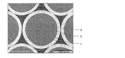
- a cross-sectional observation image by SEM of coated metal particles (solder-coated Cu core ball) having the metal particles of the embodiment according to the present invention in the core, the Ni layer in the intermediate layer, and the solder layer on the outermost surface is there. 10 is a cross-sectional enlarged observation image by SEM of a part of the coated metal particles (solder-coated Cu core ball) shown in FIG. 9.
- the metal particles, the coated metal particles, the metal powder, and the production methods thereof according to the embodiment of the present invention will be described.
- the embodiment of the present invention is not limited to those illustrated.
- the metal particle of embodiment by this invention cannot prevent mixing of elements other than P and S with the present technique, it contains trace elements other than P and S substantially.
- easily mixed elements include Pb, Bi, Sn, Sb, Zn, As, Ag, Cd, Ni, Au, U, Th, Si, Al, Cr, Se, Ca, Co, Mo, and Fe. It is done.
- oxygen due to surface oxidation is not a trace element contained in metal particles because it can be removed by an oxide film remover, but its influence cannot be ignored when the surface oxide layer becomes thick.
- the metal particles of the embodiment according to the present invention are not limited to the use of the connection terminal described above, for example, a use of mixing with a binder to form a paste, a use of mixing with resin or rubber to form a sheet, or a plating treatment It can also be applied to electrode applications such as.
- FIG. 1 shows a configuration example using metal particles according to an embodiment of the present invention.
- the solder-coated ball B uses the metal particles 1 of the embodiment according to the present invention as a core, and the surface thereof is coated with a Ni (nickel) layer 2 to form Ni-coated metal particles, and further the surface of the Ni layer 2
- Ni nickel
- the metal particle 1 serving as a core (core) has a particle size of 10 ⁇ m or more and 1000 ⁇ m or less, is composed of Cu and a trace element, and a mass ratio of Cu by GDMS analysis exceeds 99.995%.
- the total mass ratio (P + S) of S is 3 ppm or more and 30 ppm or less.
- the solder-coated ball B having the solder layer 3 is preferable because the solder layer 3 becomes molten solder by heating, so that the connection terminals described above can be easily formed and the convenience is high.
- a method for forming the solder layer 3 on the surface of the metal particle for example, dipping into molten solder, electrolytic plating in a barrel, electroless plating using a substitution reaction, and the like can be applied.
- the Ni layer 2 on the surface of the metal particle 1 as a base of the solder layer 3 containing Sn (tin).
- solder layer 3 When the solder layer 3 is directly provided on the surface of the metal particle 1 and the Ni layer 2 is not provided between the two, Cu is eluted from the metal particle 1 when the solder layer 3 becomes molten solder, for example, Cu 3 There is a possibility of forming a CuSn alloy phase such as Sn or Cu 6 Sn 5 . This is because a connection terminal having such a CuSn alloy phase is easily embrittled by hardening, and thus tends to be cracked or torn in an environment in which temperature changes are repeated.
- One of the features of the metal particles 1 of the embodiment according to the present invention is that the mass ratio of Cu in the metal particles 1 exceeds 99.995%.
- the conventional metal particles having a Cu mass ratio of 99.995% or less as determined by GDMS analysis have a finer crystal structure on the surface due to the influence of a trace element mixed therein, and the metal particles become more spherical and hardened.
- the mass ratio of Cu exceeds 99.995% and becomes high purity as in the metal particles 1 of the present invention, the influence is reduced depending on the kind and content ratio of trace elements, and the crystal structure becomes finer. It is thought that crystallization is suppressed. Therefore, when purifying metal particles with a mass ratio of Cu exceeding 99.995%, a specific trace element is selected from a number of elements, the mass ratio is appropriately determined, It is important to optimize the balance between spheroidization and softening.
- the metal particle 1 of the embodiment according to the present invention specifies P and S as trace elements, and defines the total mass ratio of P and S (P + S) as 3 ppm or more and 30 ppm or less.
- P + S is 3 ppm or more and 30 ppm or less
- the metal particles 1 when the metal particles 1 are formed, P and S easily form solidification nuclei and appropriately refine the surface structure. For this reason, spheroidization suitably proceeds without excessive hardening of the metal particles.
- the metal particles can obtain suitable sphericity and surface hardness. Therefore, the conventional annealing process which was performed in order to suitably soften the metal particles excessively hardened by rapid solidification becomes unnecessary.
- P + S is less than 3 ppm, solidification nuclei are not sufficiently formed, and the sphericity of the metal particles tends to decrease.
- P + S exceeds 30 ppm, the refinement of the crystal structure is not appropriately suppressed, the surface irregularities increase, the sphericity decreases, and the hardness of the metal particles tends to increase.
- the mass ratio of Cu in the metal particles 1 exceeds 99.995%, the mass ratio of other elements having a volume resistivity higher than that of Cu is relatively reduced, so that the volume resistivity is higher than that of Cu.
- the volume resistivity of the metal particles 1 can be reduced by the reduction amount. If the kind and content ratio of the trace elements and the production conditions of the metal particles are appropriately adjusted, for example, 4.0 ⁇ 10 ⁇ 5 ⁇ m or less, 3.0 ⁇ 10 ⁇ 5 ⁇ m or less, 2.0 ⁇ 10 such as -5 [Omega] m or less, or 1.0 ⁇ 10 -5 ⁇ m or less, it is possible to obtain metal particles 1 having a volume resistivity of desired level.
- the increase in current density is suppressed by the amount that the volume resistivity of the metal particles 1 is reduced as compared with the conventional one, and the generation of voids due to electromigration is suppressed. Further, even when exposed to a strong electric field, heat generation is suppressed by the amount by which the volume resistivity of the metal particles 1 is reduced as compared with the conventional case, and melting of the solder portion after connection is suppressed.
- a metal particle 1 having a small volume resistivity is effective in suppressing an increase in current density in a connection terminal in which a bonding area is reduced by downsizing the metal particle 1 to reduce the size.
- GDMS analysis is applied instead of the conventional ICP-AES analysis.
- the principle of GDMS analysis is that a glow discharge is generated using a sample as a cathode in an Ar (argon) atmosphere, the surface of the sample is sputtered in plasma, and ionized constituent elements are measured with a mass spectrometer. Most elements (Li to U) having stable isotopes on the periodic basis are targeted, and ppb level measurement is possible for many elements at a mass ratio.
- the mass ratio of Cu in the metal particles 1 can be measured with a resolution of 0.0001% (1 ppm) or less. Therefore, the metal particles 1 can be provided with high reliability by managing the chemical components of the metal particles 1 using the measurement values obtained by the GDMS analysis.
- Ar gas is used for sputtering of the sample and analysis is performed under a pressure at which glow discharge is generated. Therefore, for example, C (carbon), N (nitrogen), O (oxygen), etc. remaining in the Ar gas or the like. Affected by atmospheric constituent elements. Therefore, it is difficult to distinguish whether these elements are included in the sample or due to the influence of the background. Accordingly, it is preferable that the metal particles 1 whose main component is, for example, Cu, whose surface is easy to oxidize, be subjected to GDMS analysis promptly after the removal of the surface oxide layer of the sample (metal particles 1).
- the metal particles 1 of the embodiment according to the present invention have a particle size of 10 ⁇ m or more and 1000 ⁇ m or less.
- the connection gap due to the metal particle 1 is increased in three-dimensional high-density mounting such as POP or MCM. Accuracy and variation can be reduced.
- the particle size is less than 10 ⁇ m, because it is too small to ensure handling and positioning accuracy, and an element such as Cu constituting the metal particle 1 is likely to diffuse into the molten solder.
- the particle size exceeds 1000 ⁇ m, it may be too large to eliminate the substantial effect of downsizing by three-dimensional high-density mounting.
- the metal particles 1 according to the embodiment of the present invention are more purified than the conventional Cu ball (see Patent Document 1), and can have various characteristics closer to pure Cu. Therefore, the metal particles 1 of the embodiment according to the present invention can have the same Vickers hardness (refer to Patent Document 1) of 20 HV or more and 60 HV or less as in the past. Therefore, the metal particle 1 according to the embodiment of the present invention can be used in the same manner as the conventional Cu ball for applications such as the connection terminal described above, and is expected to solve the problem of increasing current density in BGA mounting and three-dimensional high-density mounting. it can.
- the metal particle manufacturing apparatus shown in FIG. 2 is mainly composed of a crucible 7 having an orifice 10 at the bottom, a vibration unit 6 having a piezoelectric element 4 and a rod 5, and an inert gas inside as indicated by an arrow 11. And a chamber 9 that can be introduced.
- a metal powder that is an aggregate of metal particles 1 can be produced.
- a metal material that is a raw material for the metal particles 1 is inserted into the crucible 7 and heated to produce a molten metal material 8.
- a metal material has a mass ratio of Cu exceeding 99.995% by GDMS analysis, and the total mass ratio of P and S among trace elements is 3 ppm or more and 30 ppm or less, and a molten metal material produced using the same 8 also has substantially similar components.
- the metal particles produced in later steps can also have substantially similar components.
- the mass ratio of the trace elements contained in the metal material is adjusted as follows, for example.
- the composition of pure copper as a master ingot is determined by GDMS analysis.
- a trace element itself that is deficient in the master ingot or a copper alloy containing the deficient element is added to the master ingot and dissolved so as to have a target composition.
- the composition of the copper alloy added to compensate for the deficient elements is also determined in advance by GDMS analysis.
- the molten metal material 8 is controlled within a predetermined temperature range in the crucible 7, and a pressure of 0.05 MPa to 1.0 MPa is applied to the crucible 7, so that the molten metal material 8 has an orifice 10 having a diameter of 5 ⁇ m to 1000 ⁇ m.
- a pressure of 0.05 MPa to 1.0 MPa is applied to the crucible 7, so that the molten metal material 8 has an orifice 10 having a diameter of 5 ⁇ m to 1000 ⁇ m.
- arrow Ba molten metal droplets that are continuously dropped are indicated by arrows Ba for the sake of simplicity.
- a molten metal droplet that becomes a metal particle after solidification is controlled to a size corresponding to the vibration period. be able to.
- Such a granulation method belongs to the UDS method.
- the pressure applied to the crucible 7 is preferably controlled in the range of 0.05 MPa or more and 1.0 MPa or less, and the ball-like molten metal droplets that can be expected to have high sphericity can be formed. . If the applied pressure is less than 0.05 MPa, the influence of friction when the molten metal material 8 passes through the orifice 10 becomes large, and the dropping of the molten metal material 8 from the orifice 10 tends to become unstable. Variations in the particle size of the metal particles produced by the solidification of the droplets are likely to increase. Further, when the applied pressure exceeds 1.0 MPa, the molten metal droplet dropped from the orifice 10 is likely to be formed into a ball shape such as an elliptical sphere. The sphericity tends to decrease.
- the diameter of the orifice 10 is preferably set to an appropriate value in consideration of the particle size and sphericity of the metal particles to be granulated and the adjustable range of the applied pressure and vibration cycle described above.
- the diameter of the orifice 10 is the opening diameter of the nozzle through which the molten metal material 8 passes. For example, when the diameter of the orifice 10 is small, adjustments such as increasing the applied pressure and lengthening the vibration cycle may be performed, and when the diameter of the orifice 10 is large, adjustment in the reverse direction when the diameter is small may be performed.
- the diameter of the orifice 10 is preferably set in the range of 5 ⁇ m or more and 1000 ⁇ m or less.
- the orifice 10 can be replaced for each granulation process, but is difficult during one granulation process. Therefore, after setting the diameter of the orifice 10 corresponding to the particle diameter of the metal particles to be granulated, it is preferable to adjust other conditions such as applied pressure and vibration cycle.
- the molten metal droplet indicated by the continuously-dropped arrow Ba is rapidly solidified by a method such as blowing an inert gas having an oxygen concentration of 1000 ppm or less.
- a method such as blowing an inert gas having an oxygen concentration of 1000 ppm or less.
- Non-oxidizing argon gas or nitrogen gas can be used as the inert gas, and the oxygen concentration is set to 1000 ppm or less for any gas.
- the oxygen concentration in the gas is increased, copper oxide is generated in the process of solidification of molten metal droplets, which becomes fine solidification nuclei and refines the solidification structure, forming a surface oxide layer on the metal particles. , The tendency for the thickness to increase.
- the removal process takes a lot of time, and there is a concern about defects related to the particle size and sphericity of the metal particles due to the removal process.
- the Ni layer when the Ni layer is formed on the surface of the metal particles having the surface oxide layer, the Ni layer may be poorly adhered or a surface form (formation spot) in which a region not having the Ni layer is mixed may be generated. If there is such a defect, the Ni layer does not function as a barrier layer that does not allow the metal particles and the solder layer to contact each other, and when the solder layer becomes a molten solder, the possibility that the CuSn alloy layer is formed as described above increases. Therefore, in the embodiment according to the present invention, an inert gas having an oxygen concentration of 1000 ppm or less is used in order to suppress the formation of the surface oxide layer of the metal particles 1.
- metal powder which is an aggregate of metal particles 1 (target particle diameter 180 ⁇ m) of the example of the present invention as an embodiment according to the present invention
- metal powder used, predetermined manufacturing conditions (additional pressure: 0.25 MPa, temperature of molten metal material 8: 1300 ° C., inert gas: nitrogen gas, oxygen concentration of inert gas: 200 ppm, pressure in chamber 9: 0.01 MPa Etc.).
- additional pressure 0.25 MPa
- temperature of molten metal material 8 1300 ° C.
- inert gas nitrogen gas
- oxygen concentration of inert gas 200 ppm
- pressure in chamber 9 0.01 MPa Etc.
- the diameter of the orifice 10 corresponding to the particle diameter of the metal particles 1 is selected by, for example, 30% to 90% of the particle diameter of the metal particles 1, and then conditions such as an additional pressure are set, The vibration period was adjusted to obtain the particle size.
- Table 1 shows the analysis results of the main component Cu and main trace elements for the produced metal particles 1. In addition, when the element did not reach the lower limit value of the analysis, the symbol ( ⁇ ) was added and the lower limit value of the element was described in Table 1.
- the particle diameter and sphericity of the metal particles in the inventive example (Nos. 1 to 5) and comparative examples (Nos. 6 to 10) that were not subjected to the annealing treatment were measured. Specifically, the metal particles placed on the flat plate were irradiated with parallel light, imaged on a CCD using a telecentric lens, and the area of the metal particles was obtained from the obtained image data. Subsequently, the equivalent circle diameter was determined from the area of the metal particles. In addition, the particle size of the metal particle in this invention is this equivalent circle diameter. Subsequently, a length ratio obtained by dividing the equivalent circle diameter by the maximum projection length obtained from the image data was obtained.
- the length ratio is the sphericity of individual metal particles.
- the sphericity of the metal particles of the present invention examples (Nos. 1 to 5) shown in Table 2 is an average value obtained by arithmetically averaging the individual sphericity of 500 metal particles by the above-described measurement method. It is.
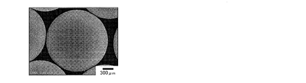
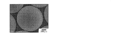
- Table 2 shows the sphericity. It was confirmed that the sphericity of the metal particles of the example of the present invention was 0.9982 or more and 0.9987 or less. On the other hand, the sphericity of the metal particles of the comparative example is 0.9973 or more and 0.9976 or less, and it can be seen that the sphericity decreases when P + S exceeds 30 ppm. Moreover, about the metal particle of this invention example (No. 3) whose P + S is 15.5 ppm, the comparative example (No. 6) whose P + S is 38.5 ppm, and the comparative example (No. 9) of 174.1 ppm FIGS.
- 3 to 5 show images observed on the surface by a scanning electron microscope (SEM: Scanning Electron Microscope). It can be seen that as P + S increases, the crystal grains become finer, the valleys of the crystal grain boundaries become deeper, and the surface irregularities become severe.
- the metal particles of the present invention examples (No. 1, 2) and comparative examples (No. 6 to 10) in the state where the annealing treatment is not performed are in accordance with the Vickers hardness test-test method (JIS-Z2244).
- JIS-Z2244 the Vickers hardness test-test method
- metal particles to be tested were embedded in a resin, polished to substantially the center of the metal particles to form a smooth cross section (plane), and the Vickers hardness of the plane was measured.
- Table 3 shows Vickers hardness. It was confirmed that the metal particles of the example of the present invention were in the preferred range (20 HV to 60 HV) equivalent to the Cu ball described in Patent Document 1 at about 53 HV to 55 HV. On the other hand, the Vickers hardness increased with the increase of P + S. 8-No. 10 was 60.2 HV or more.
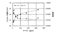
- FIG. 6 shows a scatter diagram based on P + S shown in Table 1 of the present invention and comparative examples, sphericity shown in Table 2, and Vickers hardness shown in Table 3, and approximates logarithm to Vickers hardness.
- a curve by a fourth-order polynomial approximation is also written in sphericity.
- the preferable content ratio of P + S is 30 ppm in consideration of the change in sphericity and Vickers hardness with respect to the content ratio of P + S shown in FIG. It is as follows.
- P + S is more preferably 26 ppm or less.
- P + S can be obtained at the intersection of a straight line having a sphericity of 0.9980 and an approximate curve of sphericity in FIG.
- volume resistivity (Volume resistivity)
- the volume resistivity of the metal particles in a state where the annealing treatment of the inventive examples (Nos. 1 and 2) is not performed was measured.
- the volume resistivity (Rc) of a metal powder that is an aggregate of metal particles is measured as shown in FIG. Determined by the method.
- a copper jig 14 is provided in a cylinder 13 having an inner diameter D, metal powder 12 that is an aggregate of 1.15 g of metal particles is accommodated, and an arrow 16 is opened from the opening side of the cylinder 13 by a copper piston 15.
- the distance L between the copper jig 14 and the copper piston 15 was kept constant with a load of about 22 MPa applied in the direction.
- the copper jig 14 and the copper piston 15 were produced so that their resistance values were substantially equal.
- electricity was passed between the copper jig 14 and the copper piston 15, and the resistance value Rm was measured using a commercially available resistance meter (Hioki Denki resistance meter 3541).
- the overall resistance value Rm ( ⁇ ) measured in this way, the resistance value Rj ( ⁇ ) of the copper jig 14 and the copper piston 15, the inner diameter D (m) of the cylinder 13, the copper jig 14 and the copper piston 15 From the distance L (m), the volume resistivity Rc ( ⁇ m) of the metal powder 12 was determined using the formula Rc (Rm ⁇ Rj) ⁇ ⁇ ⁇ (D / 2) 2 / L.
- x means multiplication.
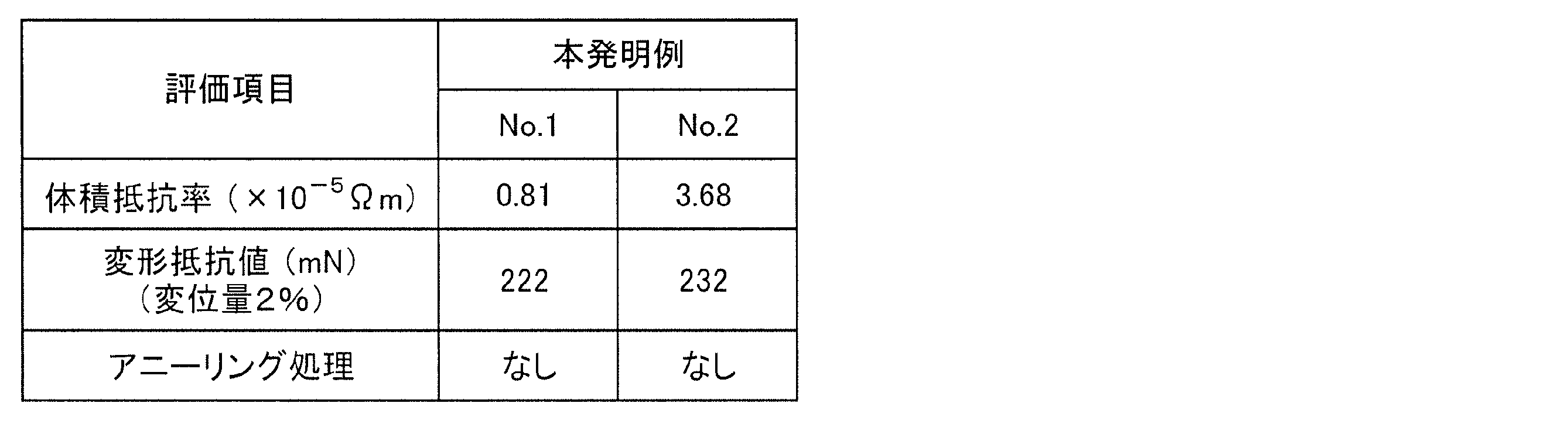
- Table 4 shows the volume resistivity.
- the volume resistivity shown in Table 4 is an average value obtained by measuring several times by the measurement method described above.
- the metal particles having this level of volume resistivity are preferable because, for example, the above-described use of the connection terminal is less likely to cause problems due to heat generation of the connection terminal portion, and in particular, this is 1.0 ⁇ 10 ⁇ 5 ⁇ m or less.
- Invention Example No. It is expected that one metal particle has a preferable effect in many applications.
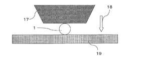
- the deformation resistance value at a displacement amount of 2% of the metal particles in the state of the invention example (Nos. 1 and 2) not subjected to the annealing treatment was measured using a micro compression tester (MCTM-500) manufactured by Shimadzu Corporation.
- the measurement was performed by the measurement method shown in FIG. Specifically, at a room temperature (20 ° C. to 25 ° C.), the metal particles placed on the flat plate 19 made of alloy tool steel (SKS) are sandwiched by the trapezoidal indenter 17 made of diamond, and then the indenter 17 is moved.
- the force (pressing force) when moved by 3.6 ⁇ m in the direction indicated by the arrow 18 at 207 mm / s (compression speed) was determined.
- the compression deformation rate of the metal particles having a particle size of 180 ⁇ m is 2% (3.6 ⁇ m / 180 ⁇ m ⁇ 100 (%))
- the amount of displacement of the metal particles at the room temperature is determined by the applied pressure at this time.
- the deformation resistance value at 2% was defined. Since metal particles having a deformation resistance value of this level are easily plastically deformed by pressurization, it is expected that, for example, in the use of the connection terminal described above, a favorable effect can be obtained in order to increase the contact area of the connection terminal portion.
- Ni-coated metal particles having a Ni layer 2 on the surface of the metal particles 1 were prepared using the metal particles 1 of the embodiment according to the present invention produced by the above-described method as nuclei (cores). Specifically, first, the metal particles 1 were put into a 10% hydrochloric acid aqueous solution at room temperature (20 ° C. to 25 ° C.) and stirred appropriately, and the oxide film formed by natural oxidation formed on the surfaces of the metal particles 1 was removed. . Thereafter, Ni plating is performed with a barrel plating apparatus using a Ni plating solution having a liquid temperature of 60 ° C. containing Ni sulfate and Ni chloride, using a Ni electrode as an anode, and a current density of 1.0 A / dm 2. The Ni layer 2 was formed on the surface.
- solder-coated metal particles solder-coated balls B having the solder layer 3 on the surface of the Ni-coated metal particles were produced.
- a cathode is provided at the circumferential portion in the plating tank, an anode is provided at the center, and the solder plating solution in the plating tank into which Ni-coated metal particles whose surface has been purified is horizontally rotated about the vertical axis, Solder plating for electrically contacting the Ni-coated metal particles with the cathode by such horizontal rotation was performed, and the solder layer 3 was formed on the surface of the Ni-coated metal particles.
- the plating solution and the plating tank are selected in the range of the horizontal rotation speed from 50 rpm to 800 rpm, the current density is selected from 0.01 A / dm 2 to 5 A / dm 2 and the horizontal rotation is performed. Control to energize at a constant speed was performed.
- the plating solution used the aqueous solution comprised by methanesulfonic acid Sn, methanesulfonic acid Ag, methanesulfonic acid Cu, a pH adjuster, etc.
- FIG. 9 shows a cross-sectional observation image by SEM of the solder-coated metal particles (solder-coated balls B) produced by the above-described method
- FIG. 10 shows a partial cross-sectional observation image by SEM.
- the solder-coated metal particles have a particle diameter of 179.9 ⁇ m as the core (core), a thickness of the Ni layer 2 of 2.2 ⁇ m, and a thickness of the solder layer 3. Was confirmed to be 17.8 ⁇ m.
- the present invention is suitably used, for example, as metal particles, coated metal particles, and production methods thereof for use in connection terminals such as BGA mounting and three-dimensional high-density mounting.
- Metal particles 2. Ni layer, 3. 3. solder layer; 4. Piezoelectric element, Rod, 6; 6. vibration unit; Crucible, 8. 8. molten metal material, Chamber, 10. 10. orifice, Arrow, 12. 12. Metal powder (aggregate of metal particles), Cylinder, 14. Copper jig, 15. Copper piston, 16. Arrow (load direction), 17. Indenter, 18. Arrow (pressure direction), 19. Flat plate; Solder coated balls, Ba. Arrow
Landscapes
- Chemical & Material Sciences (AREA)
- Engineering & Computer Science (AREA)
- Materials Engineering (AREA)
- Metallurgy (AREA)
- Organic Chemistry (AREA)
- Chemical Kinetics & Catalysis (AREA)
- Electrochemistry (AREA)
- Mechanical Engineering (AREA)
- General Chemical & Material Sciences (AREA)
- Powder Metallurgy (AREA)
- Manufacture Of Metal Powder And Suspensions Thereof (AREA)
Abstract
Description
まず、坩堝7内に、金属粒子1の原料となる金属材料を挿入して加熱し、溶融金属材料8を作製する。かかる金属材料は、GDMS分析によるCuの質量割合が99.995%を超え、微量元素のうちPとSの質量割合の合計が3ppm以上30ppm以下であり、それを用いて作製された溶融金属材料8も実質的に同様の成分を有する。よって、後の工程において作製される金属粒子もまた実質的に同様の成分を有することができる。
次いで、坩堝7内で溶融金属材料8を所定の温度範囲に制御するとともに、坩堝7内に0.05MPa以上1.0MPa以下の圧力を加え、溶融金属材料8を直径5μm以上1000μm以下のオリフィス10から矢印Baで示すように滴下してボール状の溶融金属液滴を作製する。なお、図2中では、連続的に滴下される溶融金属液滴を、簡便のため矢印Baで示している。その際、振動ユニット6を用いて坩堝7内の溶融金属材料8に所定の周期振動を付与することにより、凝固後に金属粒子になる溶融金属液滴をその振動周期に対応する大きさに制御することができる。こうした造粒方法はUDS法に属する。
上述した溶融金属液滴の作製工程の進行と同時に、酸素濃度が1000ppm以下の不活性ガスを吹き付けるなどの方法により、連続的に滴下する矢印Baで示す溶融金属液滴を急冷凝固させる。このように溶融金属液滴を急冷凝固させることにより、粒径が10μm以上1000μm以下であり、Cuと微量元素により構成され、GDMS分析によるCuの含有質量割合が99.995%を超え、微量元素のうちPとSの質量割合の合計が3ppm以上30ppm以下である、金属粒子1を作製することができる。

本発明例(No.1~5)および比較例(No.6~10)のアニーリング処理を行わない状態の金属粒子について、粒径と真球度を測定した。具体的には、平板上に載置した金属粒子に対して平行光を照射し、テレセントリックレンズを用いてCCDに結像し、得られた画像データから金属粒子の面積を求めた。続いて、その金属粒子の面積から円相当径を求めた。なお、本発明における金属粒子の粒径は、かかる円相当径のことである。続いて、その円相当径を画像データから求まる最大投影長で除した長さ比率を求めた。なお、かかる長さ比率は、個々の金属粒子の真球度である。また、表2に示す本発明例(No.1~5)の金属粒子の真球度は、上述した測定方法による500個の金属粒子の個々の真球度を算術平均して求めた平均値である。

本発明例(No.1、2)および比較例(No.6~10)のアニーリング処理を行わない状態の金属粒子について、ビッカース硬さ試験-試験方法(JIS-Z2244)に準拠し、ビッカース硬さを測定した。具体的には、被検体となる金属粒子を樹脂に埋め込み、その金属粒子のほぼ中心部まで研磨して平滑な断面(平面)を形成し、その平面のビッカース硬さを測定した。

加えて、本発明例(No.1、2)のアニーリング処理を行わない状態の金属粒子の体積抵抗率を測定した。なお、粒径が180μmである1個の金属粒子の体積抵抗率の正確な測定は困難であるため、金属粒子の集合体である金属粉体の体積抵抗率(Rc)を図7に示す測定方法により求めた。
次に、上述した方法で作製した本発明による実施形態の金属粒子1を核(コア)に用いて、かかる金属粒子1の表面にNi層2を有する、Ni被覆金属粒子を作製した。具体的には、まず、室温(20℃~25℃)の10%塩酸水溶液中に金属粒子1を投入し、適時撹拌し、金属粒子1の表面に形成された自然酸化による酸化被膜を除去した。その後、Ni電極を陽極に用いて電流密度を1.0A/dm2とし、硫酸Niと塩化Niを含む液温60℃のNiめっき液を用いたバレルめっき装置によりNiめっきを行い、金属粒子1の表面にNi層2を形成した。
続いて、上述した方法で作製したNi被覆金属粒子を用いて、かかるNi被覆金属粒子の表面にはんだ層3を有する、はんだ被覆金属粒子(はんだ被覆ボールB)を作製した。具体的には、めっき槽内の円周部に陰極を設け、中央部に陽極を設け、表面を浄化したNi被覆金属粒子を投入しためっき槽内のはんだめっき液を垂直軸で水平回転し、かかる水平回転により陰極に対してNi被覆金属粒子を電気的に接触させるはんだめっきを行い、Ni被覆金属粒子の表面にはんだ層3を形成した。この際、めっき液およびめっき槽は、水平回転数を50rpm以上800rpm以下の範囲で選定し、また、電流密度を0.01A/dm2以上5A/dm2以下の範囲で選定し、水平回転を一定速度にして通電する制御を行った。なお、めっき液は、メタンスルフォン酸Sn、メタンスルフォン酸Ag、メタンスルフォン酸Cu、およびpH調整剤などにより構成された水溶液を用いた。
Claims (6)
- 粒径が10μm以上1000μm以下であり、Cuと微量元素により構成され、GDMS分析によるCuの質量割合が99.995%を超え、前記微量元素のうちPとSの質量割合の合計が3ppm以上30ppm以下である、金属粒子。
- 請求項1に記載の金属粒子の表面がNi層で被覆されている、被覆金属粒子。
- 前記Ni層の表面がはんだ層で被覆されている、請求項2に記載の被覆金属粒子。
- 請求項1に記載の金属粒子、または請求項2または3に記載の被覆金属粒子を用いて構成された、金属粉体。
- GDMS分析によるCuの質量割合が99.995%を超え、PとSの質量割合の合計が3ppm以上30ppm以下である金属材料を、坩堝内で溶かして溶融金属材料を作製する工程aと、
前記坩堝内に0.05MPa以上1.0MPa以下の圧力を加え、前記溶融金属材料を直径5μm以上1000μm以下のオリフィスから滴下して溶融金属液滴を作製する工程bと、
前記溶融金属液滴を酸素濃度が1000ppm以下の不活性ガスを用いて急冷凝固させることにより、粒径が10μm以上1000μm以下の金属粒子を作製する工程c
とを含む、金属粒子の製造方法。 - 前記工程cの後に前記金属粒子を700℃以上の温度でアニーリングする工程を含まない、請求項5に記載の金属粒子の製造方法。
Priority Applications (3)
| Application Number | Priority Date | Filing Date | Title |
|---|---|---|---|
| JP2016546065A JP6256616B2 (ja) | 2015-04-22 | 2016-03-23 | 金属粒子およびその製造方法、被覆金属粒子、金属粉体 |
| US15/303,832 US10384314B2 (en) | 2015-04-22 | 2016-03-23 | Metal particle and method for producing the same, covered metal particle, and metal powder |
| CN201680001051.3A CN106257978B (zh) | 2015-04-22 | 2016-03-23 | 金属颗粒以及它的制造方法、包覆金属颗粒、金属粉体 |
Applications Claiming Priority (2)
| Application Number | Priority Date | Filing Date | Title |
|---|---|---|---|
| JP2015-087800 | 2015-04-22 | ||
| JP2015087800 | 2015-04-22 |
Publications (1)
| Publication Number | Publication Date |
|---|---|
| WO2016170904A1 true WO2016170904A1 (ja) | 2016-10-27 |
Family
ID=57143030
Family Applications (1)
| Application Number | Title | Priority Date | Filing Date |
|---|---|---|---|
| PCT/JP2016/059248 Ceased WO2016170904A1 (ja) | 2015-04-22 | 2016-03-23 | 金属粒子およびその製造方法、被覆金属粒子、金属粉体 |
Country Status (5)
| Country | Link |
|---|---|
| US (1) | US10384314B2 (ja) |
| JP (1) | JP6256616B2 (ja) |
| CN (1) | CN106257978B (ja) |
| TW (1) | TWI597241B (ja) |
| WO (1) | WO2016170904A1 (ja) |
Cited By (4)
| Publication number | Priority date | Publication date | Assignee | Title |
|---|---|---|---|---|
| WO2019111898A1 (ja) * | 2017-12-06 | 2019-06-13 | 千住金属工業株式会社 | Cuボール、OSP処理Cuボール、Cu核ボール、はんだ継手、はんだペースト、フォームはんだ及びCuボールの製造方法 |
| JP2019173150A (ja) * | 2018-03-27 | 2019-10-10 | 日立金属株式会社 | 金属粒子の製造方法 |
| JP2020070456A (ja) * | 2018-10-29 | 2020-05-07 | 山陽特殊製鋼株式会社 | 耐酸化性銅粉末 |
| JP2022167683A (ja) * | 2021-04-23 | 2022-11-04 | 東邦チタニウム株式会社 | 銅粉体とその製造方法 |
Families Citing this family (4)
| Publication number | Priority date | Publication date | Assignee | Title |
|---|---|---|---|---|
| JP6485580B1 (ja) * | 2018-06-12 | 2019-03-20 | 千住金属工業株式会社 | Cu核ボール、はんだ継手、はんだペースト及びフォームはんだ |
| JP6493603B1 (ja) | 2018-06-12 | 2019-04-03 | 千住金属工業株式会社 | Cu核ボール、はんだ継手、はんだペースト及びフォームはんだ |
| JP6493604B1 (ja) * | 2018-06-12 | 2019-04-03 | 千住金属工業株式会社 | Cu核ボール、はんだ継手、はんだペースト及びフォームはんだ |
| JP7775559B2 (ja) * | 2021-08-27 | 2025-11-26 | デクセリアルズ株式会社 | はんだ粒子、はんだ粒子の製造方法、及び導電性組成物 |
Citations (8)
| Publication number | Priority date | Publication date | Assignee | Title |
|---|---|---|---|---|
| JPH07166273A (ja) * | 1993-12-15 | 1995-06-27 | Sumitomo Metal Mining Co Ltd | 銅射出成形粉末冶金製品 |
| JPH117830A (ja) * | 1997-06-16 | 1999-01-12 | Alps Electric Co Ltd | 導電性材料および導電ペーストと電子機器 |
| JP2009074152A (ja) * | 2007-09-21 | 2009-04-09 | Mitsui Mining & Smelting Co Ltd | 銅粉の製造方法及び銅粉 |
| JP2013513032A (ja) * | 2009-12-07 | 2013-04-18 | ポーンサン コーポレイション | 熱プラズマを用いた高純度銅粉の製造方法 |
| JP5447745B1 (ja) * | 2013-01-11 | 2014-03-19 | 千住金属工業株式会社 | Cuボール |
| JP5585751B1 (ja) * | 2014-02-04 | 2014-09-10 | 千住金属工業株式会社 | Cuボール、Cu核ボール、はんだ継手、はんだペースト、およびフォームはんだ |
| JP5590259B1 (ja) * | 2014-01-28 | 2014-09-17 | 千住金属工業株式会社 | Cu核ボール、はんだペーストおよびはんだ継手 |
| JP5846341B1 (ja) * | 2014-11-05 | 2016-01-20 | 千住金属工業株式会社 | はんだ材料、はんだペースト、フォームはんだ、はんだ継手、およびはんだ材料の管理方法 |
Family Cites Families (23)
| Publication number | Priority date | Publication date | Assignee | Title |
|---|---|---|---|---|
| JPS545182A (en) | 1977-06-14 | 1979-01-16 | Kitamura Barubu Seizou Kk | Pure fluid switching valve |
| EP0264626A3 (de) * | 1986-10-17 | 1988-12-28 | Battelle-Institut e.V. | Verfahren zur Herstellung von dispersionsgehärteten Legierungen auf der Basis von Kupfer |
| JPH084100B2 (ja) | 1987-02-27 | 1996-01-17 | タツタ電線株式会社 | ボンディング線 |
| US4778517A (en) * | 1987-05-27 | 1988-10-18 | Gte Products Corporation | Hydrometallurgical process for producing finely divided copper and copper alloy powders |
| JPH0719790B2 (ja) | 1992-01-17 | 1995-03-06 | 株式会社日立製作所 | ボンデング用ワイヤとその製法 |
| EP1007308B1 (en) * | 1997-02-24 | 2003-11-12 | Superior Micropowders LLC | Aerosol method and apparatus, particulate products, and electronic devices made therefrom |
| JP2002317211A (ja) | 2001-04-18 | 2002-10-31 | Fukuda Metal Foil & Powder Co Ltd | 金属球製造方法 |
| JP2005036301A (ja) | 2003-06-23 | 2005-02-10 | Allied Material Corp | 微小金属球及びその製造方法 |
| JP4535786B2 (ja) * | 2004-06-18 | 2010-09-01 | 三井金属鉱業株式会社 | 含銅スズ粉、その含銅スズ粉を含む混合粉体、その含銅スズ粉の製造方法、及び、その含銅スズ粉又は混合粉体を用いた導電ペースト |
| JP4490305B2 (ja) * | 2005-02-18 | 2010-06-23 | Dowaホールディングス株式会社 | 銅粉 |
| KR100702662B1 (ko) * | 2005-02-18 | 2007-04-02 | 엠케이전자 주식회사 | 반도체 패키징용 구리 본딩 와이어 |
| EP1903119B1 (en) * | 2005-06-15 | 2015-09-23 | JX Nippon Mining & Metals Corporation | A method of manufacturing high purity copper |
| JP5036265B2 (ja) | 2005-09-21 | 2012-09-26 | 株式会社新菱 | 接続端子用ボールのめっき方法 |
| JP5088981B1 (ja) | 2011-12-21 | 2012-12-05 | 田中電子工業株式会社 | Pd被覆銅ボールボンディングワイヤ |
| KR102011166B1 (ko) * | 2012-01-17 | 2019-08-14 | 도와 일렉트로닉스 가부시키가이샤 | 은 피복 구리 합금 분말 및 그의 제조 방법 |
| EP2853617A4 (en) * | 2012-07-04 | 2016-03-09 | Jx Nippon Mining & Metals Corp | SPRAY TARGET |
| JP5219316B1 (ja) | 2012-09-28 | 2013-06-26 | 田中電子工業株式会社 | 半導体装置接続用銅白金合金細線 |
| JP5213146B1 (ja) * | 2012-10-03 | 2013-06-19 | 田中電子工業株式会社 | 半導体装置接続用銅ロジウム合金細線 |
| JP5435182B1 (ja) * | 2012-12-06 | 2014-03-05 | 千住金属工業株式会社 | Cuボール |
| EP3012047B1 (en) * | 2013-06-19 | 2018-11-21 | Senju Metal Industry Co., Ltd. | Cu-cored solder ball |
| WO2015068685A1 (ja) * | 2013-11-05 | 2015-05-14 | 千住金属工業株式会社 | Cu核ボール、はんだペースト、フォームはんだ、Cu核カラム及びはんだ継手 |
| JP5534122B1 (ja) * | 2014-02-04 | 2014-06-25 | 千住金属工業株式会社 | 核ボール、はんだペースト、フォームはんだ、フラックスコート核ボールおよびはんだ継手 |
| JP6106154B2 (ja) * | 2014-12-26 | 2017-03-29 | 千住金属工業株式会社 | はんだ材料の製造方法 |
-
2016
- 2016-03-23 WO PCT/JP2016/059248 patent/WO2016170904A1/ja not_active Ceased
- 2016-03-23 JP JP2016546065A patent/JP6256616B2/ja active Active
- 2016-03-23 CN CN201680001051.3A patent/CN106257978B/zh active Active
- 2016-03-23 US US15/303,832 patent/US10384314B2/en active Active
- 2016-04-11 TW TW105111207A patent/TWI597241B/zh active
Patent Citations (8)
| Publication number | Priority date | Publication date | Assignee | Title |
|---|---|---|---|---|
| JPH07166273A (ja) * | 1993-12-15 | 1995-06-27 | Sumitomo Metal Mining Co Ltd | 銅射出成形粉末冶金製品 |
| JPH117830A (ja) * | 1997-06-16 | 1999-01-12 | Alps Electric Co Ltd | 導電性材料および導電ペーストと電子機器 |
| JP2009074152A (ja) * | 2007-09-21 | 2009-04-09 | Mitsui Mining & Smelting Co Ltd | 銅粉の製造方法及び銅粉 |
| JP2013513032A (ja) * | 2009-12-07 | 2013-04-18 | ポーンサン コーポレイション | 熱プラズマを用いた高純度銅粉の製造方法 |
| JP5447745B1 (ja) * | 2013-01-11 | 2014-03-19 | 千住金属工業株式会社 | Cuボール |
| JP5590259B1 (ja) * | 2014-01-28 | 2014-09-17 | 千住金属工業株式会社 | Cu核ボール、はんだペーストおよびはんだ継手 |
| JP5585751B1 (ja) * | 2014-02-04 | 2014-09-10 | 千住金属工業株式会社 | Cuボール、Cu核ボール、はんだ継手、はんだペースト、およびフォームはんだ |
| JP5846341B1 (ja) * | 2014-11-05 | 2016-01-20 | 千住金属工業株式会社 | はんだ材料、はんだペースト、フォームはんだ、はんだ継手、およびはんだ材料の管理方法 |
Cited By (10)
| Publication number | Priority date | Publication date | Assignee | Title |
|---|---|---|---|---|
| WO2019111898A1 (ja) * | 2017-12-06 | 2019-06-13 | 千住金属工業株式会社 | Cuボール、OSP処理Cuボール、Cu核ボール、はんだ継手、はんだペースト、フォームはんだ及びCuボールの製造方法 |
| JP2019099883A (ja) * | 2017-12-06 | 2019-06-24 | 千住金属工業株式会社 | Cuボール、OSP処理Cuボール、Cu核ボール、はんだ継手、はんだペースト、フォームはんだ及びCuボールの製造方法 |
| KR20210049959A (ko) * | 2017-12-06 | 2021-05-06 | 센주긴조쿠고교 가부시키가이샤 | Cu 볼, OSP 처리 Cu 볼, Cu 핵 볼, 납땜 조인트, 땜납 페이스트, 폼 땜납, 및 Cu 볼의 제조 방법 |
| US11185950B2 (en) | 2017-12-06 | 2021-11-30 | Senju Metal Industry Co., Ltd. | Cu ball, Osp-treated Cu ball, Cu core ball, solder joint, solder paste, formed solder, and method for manufacturing Cu ball |
| KR102649199B1 (ko) * | 2017-12-06 | 2024-03-20 | 센주긴조쿠고교 가부시키가이샤 | Cu 볼, OSP 처리 Cu 볼, Cu 핵 볼, 납땜 조인트, 땜납 페이스트, 폼 땜납, 및 Cu 볼의 제조 방법 |
| JP2019173150A (ja) * | 2018-03-27 | 2019-10-10 | 日立金属株式会社 | 金属粒子の製造方法 |
| JP2020070456A (ja) * | 2018-10-29 | 2020-05-07 | 山陽特殊製鋼株式会社 | 耐酸化性銅粉末 |
| JP7260991B2 (ja) | 2018-10-29 | 2023-04-19 | 山陽特殊製鋼株式会社 | 耐酸化性銅粉末 |
| JP2022167683A (ja) * | 2021-04-23 | 2022-11-04 | 東邦チタニウム株式会社 | 銅粉体とその製造方法 |
| JP7643921B2 (ja) | 2021-04-23 | 2025-03-11 | 東邦チタニウム株式会社 | 銅粉体とその製造方法 |
Also Published As
| Publication number | Publication date |
|---|---|
| JP6256616B2 (ja) | 2018-01-10 |
| CN106257978B (zh) | 2019-09-24 |
| TW201702183A (zh) | 2017-01-16 |
| CN106257978A (zh) | 2016-12-28 |
| US10384314B2 (en) | 2019-08-20 |
| JPWO2016170904A1 (ja) | 2017-04-27 |
| US20180056451A1 (en) | 2018-03-01 |
| TWI597241B (zh) | 2017-09-01 |
Similar Documents
| Publication | Publication Date | Title |
|---|---|---|
| JP6256616B2 (ja) | 金属粒子およびその製造方法、被覆金属粒子、金属粉体 | |
| CN107073656B (zh) | 软钎焊材料、焊膏、成形焊料、钎焊接头以及软钎焊材料的管理方法 | |
| CN108172523B (zh) | 芯材料和半导体封装体和凸块电极的形成方法 | |
| WO2015068685A1 (ja) | Cu核ボール、はんだペースト、フォームはんだ、Cu核カラム及びはんだ継手 | |
| TW201509582A (zh) | 焊球及電子構件 | |
| TW202000934A (zh) | Cu核球、焊接頭、焊膏及泡沫焊料 | |
| CN113767469A (zh) | 芯材料、电子部件和凸点电极的形成方法 | |
| TWI761683B (zh) | Cu核球、焊接頭、焊膏及泡沫焊料 | |
| JP5585750B1 (ja) | Cu核ボール、はんだ継手、フォームはんだ、およびはんだペースト | |
| TWI755603B (zh) | Cu核球、焊接頭、焊膏及泡沫焊料 | |
| CN111386162B (zh) | Cu球、经OSP处理的Cu球、Cu芯球、钎焊接头、焊膏、成形焊料和Cu球的制造方法 | |
| JP6376266B1 (ja) | 核材料およびはんだ継手およびバンプ電極の形成方法 | |
| CN1960826A (zh) | 含铜锡粉及该含铜锡粉的制造方法以及采用了该含铜锡粉的导电膏 | |
| JP7313195B2 (ja) | 金属粉末の製造方法及び銀被覆金属粉末の製造方法 | |
| TW201534420A (zh) | 鎳球、鎳核球、軟焊接頭、軟焊膏及泡沫焊料 | |
| JP2019031735A (ja) | 表面処理銀被覆合金粉末、該粉末の製造方法、導電性ペースト、電子部品及び電気装置 | |
| CN1275734C (zh) | 无铅接合材料及使用该材料的接合方法 | |
| JP5884513B2 (ja) | Pbフリーはんだ | |
| JP6572996B1 (ja) | Cu核ボール、はんだ継手、はんだペースト及びフォームはんだ | |
| JP2004128262A (ja) | はんだ被覆ボールの製造方法、およびはんだ被覆ボール | |
| JP2005175308A (ja) | 導電性微粒子 | |
| JP6572997B1 (ja) | Cu核ボール、はんだ継手、はんだペースト及びフォームはんだ | |
| JP4338497B2 (ja) | はんだ被覆ボールの製造方法 | |
| CN113782450A (zh) | 凸点电极基板的形成方法 | |
| HK40056905A (en) | Method for forming bump electrode substrate |
Legal Events
| Date | Code | Title | Description |
|---|---|---|---|
| ENP | Entry into the national phase |
Ref document number: 2016546065 Country of ref document: JP Kind code of ref document: A |
|
| WWE | Wipo information: entry into national phase |
Ref document number: 15303832 Country of ref document: US |
|
| 121 | Ep: the epo has been informed by wipo that ep was designated in this application |
Ref document number: 16782926 Country of ref document: EP Kind code of ref document: A1 |
|
| NENP | Non-entry into the national phase |
Ref country code: DE |
|
| 122 | Ep: pct application non-entry in european phase |
Ref document number: 16782926 Country of ref document: EP Kind code of ref document: A1 |