WO2016167116A1 - 二次電池の製造方法および製造装置 - Google Patents
二次電池の製造方法および製造装置 Download PDFInfo
- Publication number
- WO2016167116A1 WO2016167116A1 PCT/JP2016/060143 JP2016060143W WO2016167116A1 WO 2016167116 A1 WO2016167116 A1 WO 2016167116A1 JP 2016060143 W JP2016060143 W JP 2016060143W WO 2016167116 A1 WO2016167116 A1 WO 2016167116A1
- Authority
- WO
- WIPO (PCT)
- Prior art keywords
- injection
- electrolyte
- pressure
- electrolytic solution
- atmospheric pressure
- Prior art date
- Legal status (The legal status is an assumption and is not a legal conclusion. Google has not performed a legal analysis and makes no representation as to the accuracy of the status listed.)
- Ceased
Links
Images


















Classifications
-
- H—ELECTRICITY
- H01—ELECTRIC ELEMENTS
- H01M—PROCESSES OR MEANS, e.g. BATTERIES, FOR THE DIRECT CONVERSION OF CHEMICAL ENERGY INTO ELECTRICAL ENERGY
- H01M10/00—Secondary cells; Manufacture thereof
- H01M10/04—Construction or manufacture in general
- H01M10/0404—Machines for assembling batteries
-
- H—ELECTRICITY
- H01—ELECTRIC ELEMENTS
- H01M—PROCESSES OR MEANS, e.g. BATTERIES, FOR THE DIRECT CONVERSION OF CHEMICAL ENERGY INTO ELECTRICAL ENERGY
- H01M10/00—Secondary cells; Manufacture thereof
- H01M10/04—Construction or manufacture in general
- H01M10/0436—Small-sized flat cells or batteries for portable equipment
- H01M10/044—Small-sized flat cells or batteries for portable equipment with bipolar electrodes
-
- H—ELECTRICITY
- H01—ELECTRIC ELEMENTS
- H01M—PROCESSES OR MEANS, e.g. BATTERIES, FOR THE DIRECT CONVERSION OF CHEMICAL ENERGY INTO ELECTRICAL ENERGY
- H01M10/00—Secondary cells; Manufacture thereof
- H01M10/04—Construction or manufacture in general
- H01M10/049—Processes for forming or storing electrodes in the battery container
-
- H—ELECTRICITY
- H01—ELECTRIC ELEMENTS
- H01M—PROCESSES OR MEANS, e.g. BATTERIES, FOR THE DIRECT CONVERSION OF CHEMICAL ENERGY INTO ELECTRICAL ENERGY
- H01M10/00—Secondary cells; Manufacture thereof
- H01M10/05—Accumulators with non-aqueous electrolyte
- H01M10/052—Li-accumulators
-
- H—ELECTRICITY
- H01—ELECTRIC ELEMENTS
- H01M—PROCESSES OR MEANS, e.g. BATTERIES, FOR THE DIRECT CONVERSION OF CHEMICAL ENERGY INTO ELECTRICAL ENERGY
- H01M10/00—Secondary cells; Manufacture thereof
- H01M10/05—Accumulators with non-aqueous electrolyte
- H01M10/056—Accumulators with non-aqueous electrolyte characterised by the materials used as electrolytes, e.g. mixed inorganic/organic electrolytes
- H01M10/0564—Accumulators with non-aqueous electrolyte characterised by the materials used as electrolytes, e.g. mixed inorganic/organic electrolytes the electrolyte being constituted of organic materials only
- H01M10/0566—Liquid materials
-
- H—ELECTRICITY
- H01—ELECTRIC ELEMENTS
- H01M—PROCESSES OR MEANS, e.g. BATTERIES, FOR THE DIRECT CONVERSION OF CHEMICAL ENERGY INTO ELECTRICAL ENERGY
- H01M10/00—Secondary cells; Manufacture thereof
- H01M10/05—Accumulators with non-aqueous electrolyte
- H01M10/058—Construction or manufacture
- H01M10/0585—Construction or manufacture of accumulators having only flat construction elements, i.e. flat positive electrodes, flat negative electrodes and flat separators
-
- H—ELECTRICITY
- H01—ELECTRIC ELEMENTS
- H01M—PROCESSES OR MEANS, e.g. BATTERIES, FOR THE DIRECT CONVERSION OF CHEMICAL ENERGY INTO ELECTRICAL ENERGY
- H01M50/00—Constructional details or processes of manufacture of the non-active parts of electrochemical cells other than fuel cells, e.g. hybrid cells
- H01M50/10—Primary casings; Jackets or wrappings
- H01M50/102—Primary casings; Jackets or wrappings characterised by their shape or physical structure
- H01M50/103—Primary casings; Jackets or wrappings characterised by their shape or physical structure prismatic or rectangular
-
- H—ELECTRICITY
- H01—ELECTRIC ELEMENTS
- H01M—PROCESSES OR MEANS, e.g. BATTERIES, FOR THE DIRECT CONVERSION OF CHEMICAL ENERGY INTO ELECTRICAL ENERGY
- H01M50/00—Constructional details or processes of manufacture of the non-active parts of electrochemical cells other than fuel cells, e.g. hybrid cells
- H01M50/10—Primary casings; Jackets or wrappings
- H01M50/102—Primary casings; Jackets or wrappings characterised by their shape or physical structure
- H01M50/105—Pouches or flexible bags
-
- H—ELECTRICITY
- H01—ELECTRIC ELEMENTS
- H01M—PROCESSES OR MEANS, e.g. BATTERIES, FOR THE DIRECT CONVERSION OF CHEMICAL ENERGY INTO ELECTRICAL ENERGY
- H01M50/00—Constructional details or processes of manufacture of the non-active parts of electrochemical cells other than fuel cells, e.g. hybrid cells
- H01M50/10—Primary casings; Jackets or wrappings
- H01M50/116—Primary casings; Jackets or wrappings characterised by the material
- H01M50/124—Primary casings; Jackets or wrappings characterised by the material having a layered structure
- H01M50/126—Primary casings; Jackets or wrappings characterised by the material having a layered structure comprising three or more layers
-
- H—ELECTRICITY
- H01—ELECTRIC ELEMENTS
- H01M—PROCESSES OR MEANS, e.g. BATTERIES, FOR THE DIRECT CONVERSION OF CHEMICAL ENERGY INTO ELECTRICAL ENERGY
- H01M50/00—Constructional details or processes of manufacture of the non-active parts of electrochemical cells other than fuel cells, e.g. hybrid cells
- H01M50/60—Arrangements or processes for filling or topping-up with liquids; Arrangements or processes for draining liquids from casings
- H01M50/609—Arrangements or processes for filling with liquid, e.g. electrolytes
- H01M50/618—Pressure control
-
- Y—GENERAL TAGGING OF NEW TECHNOLOGICAL DEVELOPMENTS; GENERAL TAGGING OF CROSS-SECTIONAL TECHNOLOGIES SPANNING OVER SEVERAL SECTIONS OF THE IPC; TECHNICAL SUBJECTS COVERED BY FORMER USPC CROSS-REFERENCE ART COLLECTIONS [XRACs] AND DIGESTS
- Y02—TECHNOLOGIES OR APPLICATIONS FOR MITIGATION OR ADAPTATION AGAINST CLIMATE CHANGE
- Y02E—REDUCTION OF GREENHOUSE GAS [GHG] EMISSIONS, RELATED TO ENERGY GENERATION, TRANSMISSION OR DISTRIBUTION
- Y02E60/00—Enabling technologies; Technologies with a potential or indirect contribution to GHG emissions mitigation
- Y02E60/10—Energy storage using batteries
-
- Y—GENERAL TAGGING OF NEW TECHNOLOGICAL DEVELOPMENTS; GENERAL TAGGING OF CROSS-SECTIONAL TECHNOLOGIES SPANNING OVER SEVERAL SECTIONS OF THE IPC; TECHNICAL SUBJECTS COVERED BY FORMER USPC CROSS-REFERENCE ART COLLECTIONS [XRACs] AND DIGESTS
- Y02—TECHNOLOGIES OR APPLICATIONS FOR MITIGATION OR ADAPTATION AGAINST CLIMATE CHANGE
- Y02P—CLIMATE CHANGE MITIGATION TECHNOLOGIES IN THE PRODUCTION OR PROCESSING OF GOODS
- Y02P70/00—Climate change mitigation technologies in the production process for final industrial or consumer products
- Y02P70/50—Manufacturing or production processes characterised by the final manufactured product
Definitions
- the present invention relates to a method and an apparatus for manufacturing a secondary battery.
- Secondary batteries are widely used as power sources for portable devices such as mobile phones, digital cameras, laptop computers, vehicle power sources, and household power sources.
- the secondary battery has a configuration in which a battery element (electrode laminate) in which a positive electrode and a negative electrode are wound or laminated while being separated by a separator is enclosed in an outer container together with an electrolytic solution.
- a battery element electrode laminate
- Patent Document 1 an electrolytic solution is injected into an outer container without particularly changing the pressure in an atmospheric pressure atmosphere, and after the injection of the electrolytic solution, the outer container is brought to a pressure lower than atmospheric pressure and higher than the vapor pressure of the electrolytic solution.
- a method for reducing the pressure and sealing the inlet (opening) of the outer container is disclosed.
- Patent Document 2 an electrolyte solution is injected into an outer container containing an electrode laminate in an atmosphere that has been reduced in pressure and substantially vacuum, and after the injection of the electrolyte solution, the inside of the outer container is pressurized to apply the electrolyte solution to the electrode.
- a method for impregnating a laminate is disclosed.
- Patent Document 3 injection of the electrolytic solution into the outer container is started in a negative pressure atmosphere of about 10 kPa (pressure about 1/10 of atmospheric pressure) reduced from atmospheric pressure, A method for completing the injection of the electrolyte before reaching a vacuum state is disclosed.
- an object of the present invention is to solve the above-mentioned problems, and to produce a secondary battery that can sufficiently impregnate an electrode stack with an electrolyte while reducing work time and production cost with simple work. To provide an apparatus.
- the method for manufacturing a secondary battery according to the present invention includes a step of inserting an electrode laminate in which a positive electrode and a negative electrode are overlapped via a separator into an outer container, and a part of the outer package before or after inserting the electrode laminate.
- the injection of the electrolytic solution is started in an atmospheric pressure atmosphere, and thereafter, the injection of the electrolytic solution and the reduction of the atmospheric pressure are performed.
- An apparatus for manufacturing a secondary battery according to the present invention includes a chamber for housing an outer container in which an electrode laminate in which a positive electrode and a negative electrode are overlapped via a separator is inserted, and an outer peripheral portion is sealed except for a part thereof, and a chamber Electrolyte injection device for injecting electrolyte solution into the outer container, pressure control device for adjusting the atmospheric pressure in the chamber, and injection of electrolyte solution into the outer container in a state where the chamber is at atmospheric pressure And a control device for controlling the electrolyte solution injection device and the pressure adjusting device so as to reduce the atmospheric pressure in the chamber in parallel with the injection of the electrolyte solution into the outer container.
- the electrode stack can be sufficiently impregnated with the electrolyte while reducing the working time and the manufacturing cost with a simple operation.
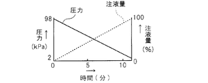
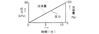
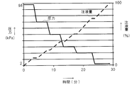
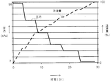
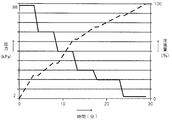
- FIG. 1 is a block diagram schematically showing a secondary battery manufacturing apparatus according to a first embodiment of the present invention. It is a graph which shows the relationship between the atmospheric pressure and the injection amount of electrolyte solution in the manufacturing method of the secondary battery of the 1st Embodiment of this invention. It is a schematic diagram which shows the impregnation state at the time of completion
- FIG. 6 is a schematic diagram showing the impregnation state after the pressurization leaving process in the manufacturing method of the secondary battery of the 1st Embodiment of this invention.
- 6 is a graph showing the relationship between the atmospheric pressure and the amount of electrolyte injected in Comparative Example 1.
- 6 is a schematic diagram showing an impregnation state at the completion of injection of an electrolytic solution in Comparative Example 1.
- FIG. 6 is a schematic diagram showing an impregnation state after a pressure leaving step in Comparative Example 1.
- FIG. It is a graph which shows the relationship between the atmospheric pressure in Comparative Example 2, and the injection amount of electrolyte solution.
- 6 is a schematic diagram showing an impregnation state at the time of completion of electrolyte injection in Comparative Example 2.
- FIG. 6 is a schematic diagram showing an impregnation state after a pressure leaving step in Comparative Example 2.
- FIG. It is a graph which shows the relationship between the atmospheric pressure in the comparative example 3, and the injection amount of electrolyte solution.
- 6 is a schematic diagram showing an impregnation state at the completion of injection of an electrolytic solution in Comparative Example 3.
- FIG. 10 is a schematic diagram showing an impregnation state after a pressure leaving step in Comparative Example 3.
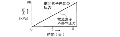
- FIG. It is a graph which shows the change of the pressure inside an electrode laminated body in Comparative Example 3, and the pressure outside an electrode laminated body. It is explanatory drawing which shows typically the state of the electrolyte solution and air in the comparative example 3 in order.
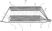
- FIGS. 1a and 1b show an example of a stacked secondary battery manufactured according to the present invention.
- the secondary battery 100 of the present invention includes a battery element (electrode laminate) 4 in which a plurality of positive electrodes (positive electrode sheets) 1 and negative electrodes (negative electrode sheets) 2 are laminated with separators 3 interposed therebetween.
- This electrode laminated body 4 is accommodated in the exterior container 6 which consists of a flexible film with the electrolyte solution 5.
- FIG. One end of a positive electrode terminal 7 is connected to the positive electrode 1 of the electrode laminate 4, and one end of a negative electrode terminal 8 is connected to the negative electrode 2.
- the other end side of the positive electrode terminal 7 and the other end side of the negative electrode terminal 8 are each drawn out of the exterior container 6.
- FIG. 1b a part of each layer constituting the electrode laminate 4 (a layer located at an intermediate portion in the thickness direction) is omitted from the illustration, and the electrolytic solution 5 is shown.
- the positive electrode 1 includes a positive electrode current collector 1a and a positive electrode active material layer 1b formed on both surfaces of the positive electrode current collector 1a.
- the negative electrode 2 includes a negative electrode current collector 2a and a negative electrode active material layer 2b formed on both surfaces of the negative electrode current collector 2a.
- One end of each of the positive electrode terminal 7 and the negative electrode terminal 8 is connected to an uncoated portion of the positive electrode current collector 1a and the negative electrode current collector 2a where the active material layers 1b and 2b are not formed.
- the material constituting the positive electrode active material layer 1b for example, LiMn 2 O 4 , LiMn 1.5 Ni 0.5 O 4 , LiMn (2-x) M x O 4 (where, M is a transition metal, and examples include spinel materials such as Ni, Co, Fe, Cr), LiCoO 2 , LiNiO 2 , LiNi (1-x) CoO 2 , LiNi x (CoAl) (1- x) Layered oxide materials such as O 2 , Li 2 MnO 3 —LiMO 2 , LiNi x Co y Mn (1-xy) O 2 , olivine materials such as LiMPO 4 , Li 2 MPO 4 F, Li Fluorine olivine-based materials such as 2 MSiO 4 F and vanadium oxide-based materials such as V 2 O 5 can be used.
- Materials constituting the negative electrode active material layer 2b include carbon materials such as graphite, amorphous carbon, diamond-like carbon, fullerene, carbon nanotube, and carbon nanohorn, lithium metal materials, alloy materials such as silicon and tin, Nb An oxide-based material such as 2 O 5 or TiO 2 or a composite thereof can be used.
- the positive electrode active material layer 1b and the negative electrode active material layer 2b may be formed of a mixture in which a binder, a conductive auxiliary agent, or the like is appropriately added to the materials described above.
- a conductive support agent 1 type in carbon black, carbon fiber, or graphite can be used, or a combination of 2 or more types can be used.
- the binder polyvinylidene fluoride (PVDF), polytetrafluoroethylene, carboxymethyl cellulose, modified acrylonitrile rubber particles, and the like can be used.
- positive electrode current collector 1a aluminum, stainless steel, nickel, titanium, or an alloy thereof can be used, and aluminum is particularly preferable.
- negative electrode current collector 2a copper, stainless steel, nickel, titanium, or an alloy thereof can be used.
- Examples of the electrolytic solution 5 include cyclic carbonates such as ethylene carbonate, propylene carbonate, vinylene carbonate, butylene carbonate, ethyl methyl carbonate (EMC), diethyl carbonate (DEC), dimethyl carbonate (DMC), dipropyl carbonate (DPC), and the like.
- cyclic carbonates such as ethylene carbonate, propylene carbonate, vinylene carbonate, butylene carbonate, ethyl methyl carbonate (EMC), diethyl carbonate (DEC), dimethyl carbonate (DMC), dipropyl carbonate (DPC), and the like.
- One or more organic solvents such as chain carbonates, aliphatic carboxylic acid esters, ⁇ -lactones such as ⁇ -butyrolactone, chain ethers, cyclic ethers, etc. Mixtures can be used. Lithium salts can be dissolved in these organic solvents.
- the separator 3 is mainly made of a resin porous film, woven fabric, non-woven fabric, etc., and as its resin component, for example, a polyolefin resin such as polypropylene or polyethylene, a polyester resin, an acrylic resin, a styrene resin, or a nylon resin is used. it can.
- a polyolefin-based microporous membrane is preferable because of its excellent ion permeability and performance of physically separating the positive electrode 1 and the negative electrode 2.
- the inorganic particles include insulating oxides, nitrides, sulfides, carbides, etc. Among them, it is preferable that TiO 2 or Al 2 O 3 is included.
- the exterior container 6 is made of a flexible film, and a flexible film having a resin layer on the front and back surfaces of a metal layer serving as a substrate can be used.
- a metal layer having barrier properties such as leakage of the electrolytic solution 5 and prevention of moisture from the outside can be selected, and aluminum, stainless steel, or the like can be used.
- a heat-fusible resin layer such as a modified polyolefin is provided.
- the exterior container 6 is formed by making the heat-fusible resin layers of the flexible film face each other and heat-sealing the periphery of the portion that accommodates the electrode laminate 4.
- a resin layer such as a nylon film or a polyester film can be provided on the surface of the outer container that is the surface opposite to the surface on which the heat-fusible resin layer is formed.
- the positive terminal 7 can be made of aluminum or aluminum alloy.
- the negative electrode terminal 8 can be made of copper, a copper alloy, or nickel plated on them.
- FIG. 2 shows a basic configuration of a manufacturing apparatus for manufacturing the secondary battery 100 as shown in FIGS. 1a to 1b.
- the secondary battery manufacturing apparatus can accommodate a secondary battery 100 and can be sealed, and an electrolyte injection device 10 that injects the electrolyte 5 into the outer container 6 of the secondary battery 100 in the chamber 9.
- a pressure adjusting device 11 that adjusts the atmospheric pressure in the chamber 9, and a control device 12 that controls the electrolyte injection device 10 and the pressure adjusting device 11. Therefore, the atmospheric pressure can be increased or decreased by the pressure adjusting device 11 in a state where the secondary battery 100 is accommodated in the chamber 9.
- the electric field liquid 5 can be injected into the outer container 6 of the secondary battery 100 in the chamber 9.
- the control device 12 controls the pressure adjusting device 11 and the electrolyte solution injection device 10 to determine the timing of electrolyte solution injection and pressure reduction.
- a method of manufacturing the secondary battery 100 shown in FIGS. 1a and 1b using the manufacturing apparatus shown in FIG. 2 will be described.
- the electrode laminate 4 is formed by alternately laminating 3.
- the electrode laminate 4 is inserted into the outer container 6.
- the outer container 6 is a bag made of a flexible film, and before or after the electrode laminate 4 is inserted, the flexible films that overlap at a position corresponding to the outside of the outer peripheral portion of the electrode laminate 4 are partly excluded.
- the overlapping flexible films are not directly joined to each other, but to the position where they are in close contact with the outer edge portions of the positive electrode terminal 7 and the negative electrode terminal 8.
- the flexible films are bonded to each other and sealed so as not to generate a gap.
- the electrolytic solution 5 is injected in a state where the electrode laminate 4 is inserted into the sealed outer container 6 except for a part (injection port 6a).
- the outer container 6 is disposed in the chamber 9, and the controller 12 operates the pressure regulator 11 to gradually depressurize the chamber 9 from atmospheric pressure (for example, 98 kPa).
- the injection device 10 is operated to inject the electrolytic solution 5 into the outer container 6 from the injection port 6a. That is, as shown in FIG.
- the injection of the electrolytic solution 5 is started in an atmospheric pressure atmosphere, and the pressure in the chamber 9 (atmospheric pressure) is gradually reduced, and at the same time, the electrolytic solution 5 enters the outer container 6, Finally, the injection of a predetermined amount of the electrolyte 5 is completed in an atmosphere reduced to near the vapor pressure of the electrolyte 5.
- the decompression stop pressure is set to 2 kPa. Thereafter, the unsealed portion used as the inlet 6a is sealed. According to such an injection method of the electrolytic solution 5, the impregnation of the electric field solution 5 into the electrode laminate 4 is very good. Thereafter, the pressure reduction by the pressure adjusting device 11 is released, and the inside of the chamber 9 is returned to the atmospheric pressure. Then, if necessary, the outer container 6 may be physically pressurized to promote the impregnation of the electrolytic solution.
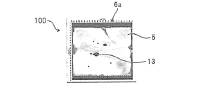
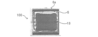
- FIG. 3B shows a state in which the electrolytic solution 5 is injected according to the above-described embodiment.
- the light gray color in the drawing is the electrolytic solution 5 and the air 13 is black.
- the penetration rate was 62.4%.
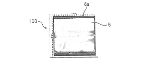
- the electrode laminate 4 is left for about 18 hours in a physically pressurized state and the penetration of the electrolyte solution 5 is promoted by utilizing the capillary phenomenon, as shown in FIG.
- About 99.9% of the electrolyte solution 5 was impregnated with the electrolyte solution 5.
- the permeation rate is a value obtained by dividing the area of the portion impregnated with the electrolytic solution 5 by the area of the entire electrode laminate and multiplying by 100 to indicate the percentage.
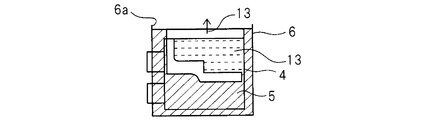
- the electrolyte 5 enters the inside of the electrode stack 4 due to an increase in pressure, and at the same time, the air 13 also enters the electrode stack 4. That is, the electrolytic solution 5 and the air 13 enter the electrode laminate 4 at the same time. Therefore, as shown in FIG. 7 a, there is almost no pressure difference between the inside and outside of the electrode stack 4, and the electrolyte 5 is contained inside the electrode stack 4 by the amount of air 13 that has entered the inside of the electrode stack 4. A part that cannot be penetrated is generated. And even if injection
- the pressure inside and outside the electrode laminate 4 is almost the same at the start of injection of the electrolytic solution 5. Then, when the pressure is gradually reduced, the pressure decreases outside the electrode laminate 4, but suddenly drops in the electrode laminate 4 due to a relatively complicated internal structure (laminate structure). Is unlikely to occur. That is, the pressure decreases in proportion to the time outside the electrode stack 4, whereas the pressure decrease is moderate inside the electrode stack 4. This means that a pressure difference is generated between the inside and the outside of the electrode laminate 4. Then, as shown in FIGS.
- the air 13 accumulated in the electrode laminate 4 is moved from the inside of the electrode laminate 4 having a relatively high pressure to the outside of the electrode laminate 4 having a relatively low pressure. Try to spill toward.
- the electrolytic solution 5 is continuously injected from the injection port 6 a toward the inside of the electrode stack 4. Accordingly, the gas (air 13) and the liquid (electrolyte 5) are replaced inside and outside the electrode laminate 4, and the electrolyte 5 intrudes and the air 13 flows out inside the electrode laminate 4.
- the electrolytic solution 5 is efficiently impregnated in the electrode laminate 4. For this reason, according to this embodiment, as shown in FIG. 8e, a sufficient amount of electrolyte can be injected very efficiently.
- [Modification] 9a to 9c show a modification of the present embodiment.
- the step of injecting the electrolytic solution 5 is different from the example described above. Since the steps other than the step of injecting the electrolytic solution 5 and the configuration of the apparatus are the same as the above-described example, the description thereof is omitted.
- the pressure reduction rate is faster than the injection of the electrolytic solution 5, so the pressure in the chamber 9 (atmosphere) during the injection of the electrolytic solution 5 Pressure) reaches the decompression stop pressure (2 kPa). Thereafter, the pressure in the chamber 9 is gradually returned to the atmospheric pressure, and the injection of the electrolytic solution 5 continues in parallel with that.
- the second embodiment of the present invention differs from the first embodiment only in the step of injecting the electrolytic solution 5. Since the steps other than the step of injecting the electrolytic solution 5 and the configuration of the apparatus are the same as those in the first embodiment, description thereof will be omitted.
- the step of injecting the electrolytic solution 5 of the present embodiment as shown in FIGS. 10 to 12, the pressure in the chamber is reduced stepwise and the injection of the electrolytic solution 5 is performed intermittently. And alternately injecting. According to this embodiment, since the pressure reduction and the injection of the electrolyte solution 5 are not performed simultaneously, the injection amount of the electrolyte solution 5 can be increased smoothly without disturbing the liquid surface.
- the decompression and the injection of the electrolyte 5 are interrupted too little, the work time becomes long and the efficiency is poor, so that the pressure drop is -10 kPa or more in one decompression step and one injection step Then, it is preferable to set so that liquid injection of 6% or more of the final total liquid injection volume is performed. It is preferable that the decompression and the injection of the electrolyte solution 5 are each performed by dividing into about 7 stages or less.
- the injection amount may be reduced at each stage of the first half of the injection process, and the injection volume may be increased at each stage of the second half.
- the amount of liquid injection may be increased at each stage of the first half of the liquid injection process, and the volume of liquid injection may be decreased at each stage of the second half.
- the pressure in the chamber 9 (atmospheric pressure) is started to be reduced from atmospheric pressure, and at the same time, the injection of the electrolyte 5 into the outer container 6 is started.
- it is preferable to start the injection of the electrolytic solution 5 while the pressure in the chamber is up to about atmospheric pressure ⁇ 10 kPa.
Landscapes
- Chemical & Material Sciences (AREA)
- Chemical Kinetics & Catalysis (AREA)
- Electrochemistry (AREA)
- General Chemical & Material Sciences (AREA)
- Engineering & Computer Science (AREA)
- Manufacturing & Machinery (AREA)
- Physics & Mathematics (AREA)
- Condensed Matter Physics & Semiconductors (AREA)
- General Physics & Mathematics (AREA)
- Inorganic Chemistry (AREA)
- Secondary Cells (AREA)
- Filling, Topping-Up Batteries (AREA)
Abstract
Description
[二次電池の基本構造]
図1a~1bに、本発明によって製造される積層型の二次電池の一例を示している。本発明の二次電池100は、正極(正極シート)1と負極(負極シート)2とがセパレータ3を介して交互に複数層積層された電池素子(電極積層体)4を備えている。この電極積層体4は電解液5とともに、可撓性フィルムからなる外装容器6内に収容されている。電極積層体4の正極1には正極端子7の一端が、負極2には負極端子8の一端がそれぞれ接続されている。正極端子7の他端側および負極端子8の他端側は、それぞれ外装容器6の外部に引き出されている。図1bでは、電極積層体4を構成する各層の一部(厚さ方向の中間部に位置する層)を図示省略して、電解液5を示している。
図2には、図1a~1bに示すような二次電池100を製造するための製造装置の基本構成を示している。この二次電池の製造装置は、二次電池100を収容可能であり密閉可能なチャンバ9と、チャンバ9内の二次電池100の外装容器6内に電解液5を注入する電解液注入装置10と、チャンバ9内の雰囲気圧力を調節する圧力調節装置11と、電解液注入装置10と圧力調節装置11とを制御する制御装置12と、を有している。従って、チャンバ9内に二次電池100が収容された状態で、圧力調節装置11によって雰囲気圧力を上昇させたり低下させたりすることができる。また、チャンバ9内の二次電池100の外装容器6内に電界液5を注入することができる。そして、制御装置12が圧力調節装置11と電解液注入装置10を制御して、電解液注入と減圧のタイミングを決めている。
図2に示す製造装置を用いて、図1a~1bに示す二次電池100を製造する方法について説明する。
まず、正極集電体1aの両面に正極活物質層1bが形成された複数の正極1と、負極集電体2aの両面に負極活物質層2bが形成された複数の負極2とを、セパレータ3を挟んで交互に積層して電極積層体4を形成する。そして、この電極積層体4を外装容器6内に挿入する。外装容器6は、可撓性フィルムからなる袋状であり、電極積層体4を挿入する前または後に、電極積層体4の外周部の外側にあたる位置で重なり合う可撓性フィルム同士が、一部分を除いて互いに接合されることにより封止されている。この時に封止されない部分は、電解液5を注入する際の注入口6aとなる。また、厳密に言うと、正極端子7および負極端子8が挿通する部分では、重なり合う可撓性フィルム同士が直接接合されてはいないが、正極端子7および負極端子8の外縁部に密着する位置まで可撓性フィルム同士が接合されて、隙間が生じないように封止されている。
この電界液5の注入方法について、実際に実験した結果に基づいて評価する。前述した実施形態により電解液5を注入した状態を図3bに示している。図面中の薄い灰色は電解液5であって、黒く見えるのは空気13である。図3bに示す状態では、電極積層体4全体のうちのおよそ62.4%に電解液5が含浸されていた(浸み込み率が62.4%であった)。さらに、電極積層体4を物理的に加圧した状態で18時間程度放置し、毛細管現象を利用して電解液5の浸透を促進すると、図3cに示すように、電極積層体4全体のうちのおよそ99.9%に電解液5が含浸された。すなわち、ほぼ完全な電解液5の含浸が実現した。なお、同様な実験を複数回繰り返したところ、加圧放置工程後の浸み込み率は、99.9%,99.0%,97.7%,98.4%という結果であった。浸み込み率とは、電解液5が含浸した部分の面積を電極積層体全体の面積で割り、100倍して百分率表示で示した値である。
図9a~9cに本実施形態の変形例を示している。この変形例では、電解液5を注入する工程のみが前述した例と異なる。電解液5を注入する工程以外の各工程や装置の構成は、前述した例と同様であるため説明を省略する。この変形例の電解液5を注入する工程では、図9aに示すように、電解液5の注入に比べて減圧の速度が速いため、電解液5の注入の途中でチャンバ9内の圧力(雰囲気圧力)が減圧停止圧力(2kPa)に到達する。その後、チャンバ9内の圧力は徐々に大気圧に戻され、それと並行して電解液5の注入は続行する。最終的に、チャンバ9内の圧力がほぼ大気圧に戻った時に、所定量の電解液5の注入が完了する。この変形例でも、図9bに示すように電極積層体4の内部への電解液5の良好な含浸が行われ、図9cに示すように加圧放置工程後には浸み込み率がさらに向上する。
本発明の第2の実施形態は、電解液5を注入する工程のみが第1の実施形態と異なる。電解液5を注入する工程以外の各工程や装置の構成は、第1の実施形態と同様であるため説明を省略する。本実施形態の電解液5を注入する工程では、図10~12に示すように、チャンバ内の圧力を段階的に減圧するとともに、電解液5の注入を間欠的に行い、減圧と電解液5の注入とを交互に行う。本実施形態によると、減圧と電解液5の注入とを同時に行わないので、液面が乱れることなく円滑に電解液5の注入量を増やしていくことができる。ただし、減圧と電解液5の注入をあまり小刻みに中断すると、作業時間が長くなり効率が悪いので、1回の減圧段階では-10kPa以上の圧力低下となるように、かつ1回の注液段階では、最終的な注液総量の6%以上の注液を行うように設定することが好ましい。減圧および電解液5の注入は、それぞれ7段階以下程度に分割して行うことが好ましい。
2 負極
3 セパレータ
4 電極積層体(電池素子)
5 電解液
6 外装容器
7 正極端子
8 負極端子
9 チャンバ
10 電解液注入装置
11 圧力調節装置
12 制御装置
100 二次電池
Claims (7)
- 正極と負極がセパレータを介して重ね合わされた電極積層体を外装容器内に挿入する工程と、前記電極積層体を挿入する前または後に、一部分を除いて前記外装容器の外周部を封止する工程と、前記電極積層体が挿入された前記外装容器内に、未封止の前記一部分を注入口として電解液を注入する工程と、を含み、前記電解液を注入する工程では、大気圧雰囲気において前記電解液の注入を開始し、その後に、前記電解液の注入と雰囲気圧力の減圧とを行う、二次電池の製造方法。
- 前記電解液の注入と雰囲気圧力の減圧とを同時に並行して行う、請求項1に記載の二次電池の製造方法。
- 前記電解液の注入と雰囲気圧力の減圧は間欠的に行い、前記電解液の注入と雰囲気圧力の減圧とを交互に行う、請求項1に記載の二次電池の製造方法。
- 雰囲気圧力は、前記電解液の蒸気圧よりも高い減圧停止圧力まで減圧する、請求項1から3のいずれか1項に記載の二次電池の製造方法。
- 雰囲気圧力を前記減圧停止圧力まで減圧した後に大気圧に戻す、請求項4に記載の二次電池の製造方法。
- 雰囲気圧力を前記減圧停止圧力まで減圧した後に大気圧に戻す段階においても、前記電解液の注入を続行する、請求項5に記載の二次電池の製造方法。
- 正極と負極がセパレータを介して重ね合わされた電極積層体が挿入され、一部分を除いて外周部が封止されている外装容器を収容するチャンバと、
前記チャンバ内の前記外装容器内に電解液を注入する電解液注入装置と、
前記チャンバ内の雰囲気圧力を調節する圧力調節装置と、
前記チャンバ内が大気圧雰囲気である状態で前記外装容器内に電解液の注入を開始し、前記外装容器内への前記電解液の注入と並行して前記チャンバ内の雰囲気圧力を減圧するように、前記電解液注入装置と前記圧力調節装置を制御する制御装置と、
を有する、二次電池の製造装置。
Priority Applications (2)
| Application Number | Priority Date | Filing Date | Title |
|---|---|---|---|
| JP2017512256A JP6847348B2 (ja) | 2015-04-16 | 2016-03-29 | 二次電池の製造方法および製造装置 |
| US15/566,064 US10476097B2 (en) | 2015-04-16 | 2016-03-29 | Method of manufacturing secondary battery and apparatus for the same |
Applications Claiming Priority (2)
| Application Number | Priority Date | Filing Date | Title |
|---|---|---|---|
| JP2015-084219 | 2015-04-16 | ||
| JP2015084219 | 2015-04-16 |
Publications (1)
| Publication Number | Publication Date |
|---|---|
| WO2016167116A1 true WO2016167116A1 (ja) | 2016-10-20 |
Family
ID=57125874
Family Applications (1)
| Application Number | Title | Priority Date | Filing Date |
|---|---|---|---|
| PCT/JP2016/060143 Ceased WO2016167116A1 (ja) | 2015-04-16 | 2016-03-29 | 二次電池の製造方法および製造装置 |
Country Status (3)
| Country | Link |
|---|---|
| US (1) | US10476097B2 (ja) |
| JP (1) | JP6847348B2 (ja) |
| WO (1) | WO2016167116A1 (ja) |
Cited By (2)
| Publication number | Priority date | Publication date | Assignee | Title |
|---|---|---|---|---|
| JP2022134410A (ja) * | 2021-03-03 | 2022-09-15 | 株式会社東芝 | 注液装置及び注液方法 |
| JP2023081159A (ja) * | 2021-11-30 | 2023-06-09 | プライムプラネットエナジー&ソリューションズ株式会社 | 二次電池の製造方法 |
Families Citing this family (3)
| Publication number | Priority date | Publication date | Assignee | Title |
|---|---|---|---|---|
| CN110828903B (zh) * | 2019-11-06 | 2023-05-02 | 风帆有限责任公司 | 一种软包装锂离子电池的电芯浸润方法 |
| CN110890586A (zh) * | 2019-12-02 | 2020-03-17 | 天津昊宸智能科技有限公司 | 一种电池极片的叠片装置及叠片方法 |
| KR20230044239A (ko) * | 2020-07-31 | 2023-04-03 | 가부시키가이샤 한도오따이 에네루기 켄큐쇼 | 이차 전지의 제작 방법 및 이차 전지의 제조 장치 |
Citations (9)
| Publication number | Priority date | Publication date | Assignee | Title |
|---|---|---|---|---|
| JP2004022208A (ja) * | 2002-06-12 | 2004-01-22 | Nissan Motor Co Ltd | 組電池 |
| JP2005285646A (ja) * | 2004-03-30 | 2005-10-13 | Tdk Corp | 電池パック |
| JP2008059973A (ja) * | 2006-09-01 | 2008-03-13 | Matsushita Electric Ind Co Ltd | リチウム二次電池の注液方法および注液装置 |
| JP2008171579A (ja) * | 2007-01-09 | 2008-07-24 | Hitachi Maxell Ltd | リチウムイオン二次電池およびリチウムイオン二次電池の組電池 |
| JP2010055950A (ja) * | 2008-08-28 | 2010-03-11 | Nissan Motor Co Ltd | 電池の製造方法 |
| JP2011154859A (ja) * | 2010-01-27 | 2011-08-11 | Panasonic Corp | 芯棒、非水電解質二次電池用捲回型電極群ならびに非水電解質二次電池及びその製造方法 |
| JP2011171159A (ja) * | 2010-02-19 | 2011-09-01 | Mitsubishi Heavy Ind Ltd | 電解液注液装置 |
| JP2013026172A (ja) * | 2011-07-26 | 2013-02-04 | Gs Yuasa Corp | 電池 |
| JP2013105564A (ja) * | 2011-11-11 | 2013-05-30 | Nissan Motor Co Ltd | 電気デバイスの製造方法及びその製造装置並びに電気デバイス |
Family Cites Families (12)
| Publication number | Priority date | Publication date | Assignee | Title |
|---|---|---|---|---|
| JPH07118307B2 (ja) | 1988-09-14 | 1995-12-18 | 古河電池株式会社 | 蓄電池への電解液の注液法並びに注液機 |
| JP2002529333A (ja) * | 1998-11-18 | 2002-09-10 | イー.エム. ジョーンズ、ウィリアム | 液体を所定レベルに充填する自動液体充填装置及び方法 |
| US6485862B1 (en) | 1998-12-28 | 2002-11-26 | Mitsubishi Denki Kabushiki Kaisha | Thin battery and method of manufacturing |
| US6379838B1 (en) * | 1999-04-14 | 2002-04-30 | Alcatel | Cell package |
| US6248138B1 (en) * | 1999-06-09 | 2001-06-19 | Delphi Technologies, Inc. | Activation and sealing of storage batteries |
| JP2001110400A (ja) * | 1999-10-04 | 2001-04-20 | Nec Mobile Energy Kk | 電解液注入装置および電解液注入方法 |
| EP1481429B1 (de) * | 2002-03-08 | 2006-05-31 | Epcos Ag | Verfahren und vorrichtung zum einfüllen flüchtiger flüssigkeiten in gehäuse elektrischer bauelemente und zum verschliessen der gehäuse |
| JP4561034B2 (ja) | 2003-02-05 | 2010-10-13 | パナソニック株式会社 | 非水電解液電池の製造方法 |
| JP4291194B2 (ja) | 2004-03-30 | 2009-07-08 | Tdk株式会社 | 液含浸方法及び液含浸装置 |
| JP5585174B2 (ja) * | 2010-04-07 | 2014-09-10 | 日産自動車株式会社 | 電解液注液方法および電解液注液装置 |
| JP5331946B1 (ja) * | 2012-07-05 | 2013-10-30 | オー・エム・シー株式会社 | 電解液の注液方法とその注液装置 |
| JP2014022336A (ja) | 2012-07-23 | 2014-02-03 | Sharp Corp | 非水系二次電池の注液装置および注液方法 |
-
2016
- 2016-03-29 WO PCT/JP2016/060143 patent/WO2016167116A1/ja not_active Ceased
- 2016-03-29 JP JP2017512256A patent/JP6847348B2/ja active Active
- 2016-03-29 US US15/566,064 patent/US10476097B2/en active Active
Patent Citations (9)
| Publication number | Priority date | Publication date | Assignee | Title |
|---|---|---|---|---|
| JP2004022208A (ja) * | 2002-06-12 | 2004-01-22 | Nissan Motor Co Ltd | 組電池 |
| JP2005285646A (ja) * | 2004-03-30 | 2005-10-13 | Tdk Corp | 電池パック |
| JP2008059973A (ja) * | 2006-09-01 | 2008-03-13 | Matsushita Electric Ind Co Ltd | リチウム二次電池の注液方法および注液装置 |
| JP2008171579A (ja) * | 2007-01-09 | 2008-07-24 | Hitachi Maxell Ltd | リチウムイオン二次電池およびリチウムイオン二次電池の組電池 |
| JP2010055950A (ja) * | 2008-08-28 | 2010-03-11 | Nissan Motor Co Ltd | 電池の製造方法 |
| JP2011154859A (ja) * | 2010-01-27 | 2011-08-11 | Panasonic Corp | 芯棒、非水電解質二次電池用捲回型電極群ならびに非水電解質二次電池及びその製造方法 |
| JP2011171159A (ja) * | 2010-02-19 | 2011-09-01 | Mitsubishi Heavy Ind Ltd | 電解液注液装置 |
| JP2013026172A (ja) * | 2011-07-26 | 2013-02-04 | Gs Yuasa Corp | 電池 |
| JP2013105564A (ja) * | 2011-11-11 | 2013-05-30 | Nissan Motor Co Ltd | 電気デバイスの製造方法及びその製造装置並びに電気デバイス |
Cited By (4)
| Publication number | Priority date | Publication date | Assignee | Title |
|---|---|---|---|---|
| JP2022134410A (ja) * | 2021-03-03 | 2022-09-15 | 株式会社東芝 | 注液装置及び注液方法 |
| JP2023081159A (ja) * | 2021-11-30 | 2023-06-09 | プライムプラネットエナジー&ソリューションズ株式会社 | 二次電池の製造方法 |
| JP7503040B2 (ja) | 2021-11-30 | 2024-06-19 | プライムプラネットエナジー&ソリューションズ株式会社 | 二次電池の製造方法 |
| US12424715B2 (en) | 2021-11-30 | 2025-09-23 | Prime Planet Energy & Solutions, Inc. | Method for manufacturing secondary battery |
Also Published As
| Publication number | Publication date |
|---|---|
| JPWO2016167116A1 (ja) | 2018-02-15 |
| US20180131029A1 (en) | 2018-05-10 |
| US10476097B2 (en) | 2019-11-12 |
| JP6847348B2 (ja) | 2021-03-24 |
Similar Documents
| Publication | Publication Date | Title |
|---|---|---|
| JP6418650B2 (ja) | 積層型二次電池および電極の製造方法 | |
| US10217988B2 (en) | Secondary battery | |
| JP5593454B2 (ja) | バッテリセルの製造方法、及びその製造方法で製造されたバッテリセル | |
| JP6381045B2 (ja) | 二次電池 | |
| JP6637955B2 (ja) | リチウムイオン二次電池の製造方法 | |
| JP4187870B2 (ja) | 電池の製造方法 | |
| KR101838350B1 (ko) | 젖음성이 개선된 전기화학소자용 전극 조립체 및 이의 제조 방법 | |
| JP6847348B2 (ja) | 二次電池の製造方法および製造装置 | |
| JP2005293950A (ja) | リチウムイオン二次電池、及び、リチウムイオン二次電池の充電方法 | |
| WO2015129320A1 (ja) | 二次電池用電極および二次電池とそれらの製造方法 | |
| CN105706275A (zh) | 电极及具有电极的电池 | |
| JP6992436B2 (ja) | リチウムイオン二次電池用電解液およびリチウムイオン二次電池 | |
| WO2014203424A1 (ja) | 二次電池と電極の製造方法 | |
| JP2017529659A (ja) | 加圧部を含む円筒型電池及びその製造方法 | |
| JP6739425B2 (ja) | 二次電池用の電極および二次電池の製造方法と製造装置 | |
| JP2013206699A (ja) | 電気化学デバイス | |
| JP2005285647A (ja) | 電源 | |
| JP6606341B2 (ja) | 電極および電池 | |
| JP2018045952A (ja) | 電極及び電気化学デバイスの製造方法と電極ロール | |
| WO2018163295A1 (ja) | 二次電池および二次電池の製造方法 | |
| JP2002231196A (ja) | 薄形電池の製造方法 | |
| JP7024540B2 (ja) | 電気化学素子 | |
| KR102439773B1 (ko) | 이차 전지의 제조 방법 및 이차 전지의 함침 방법 | |
| JP2003217671A (ja) | 密閉型電池の製造方法と密閉型電池のシール性評価方法 | |
| KR20150015387A (ko) | 개별식 전해액 주입장치 |
Legal Events
| Date | Code | Title | Description |
|---|---|---|---|
| 121 | Ep: the epo has been informed by wipo that ep was designated in this application |
Ref document number: 16779907 Country of ref document: EP Kind code of ref document: A1 |
|
| ENP | Entry into the national phase |
Ref document number: 2017512256 Country of ref document: JP Kind code of ref document: A |
|
| WWE | Wipo information: entry into national phase |
Ref document number: 15566064 Country of ref document: US |
|
| NENP | Non-entry into the national phase |
Ref country code: DE |
|
| 122 | Ep: pct application non-entry in european phase |
Ref document number: 16779907 Country of ref document: EP Kind code of ref document: A1 |