WO2016162940A1 - 非接触受電装置の温度推定装置及び温度推定方法 - Google Patents
非接触受電装置の温度推定装置及び温度推定方法 Download PDFInfo
- Publication number
- WO2016162940A1 WO2016162940A1 PCT/JP2015/060814 JP2015060814W WO2016162940A1 WO 2016162940 A1 WO2016162940 A1 WO 2016162940A1 JP 2015060814 W JP2015060814 W JP 2015060814W WO 2016162940 A1 WO2016162940 A1 WO 2016162940A1
- Authority
- WO
- WIPO (PCT)
- Prior art keywords
- power
- coil
- temperature
- power transmission
- transmission coil
- Prior art date
Links
- 238000000034 method Methods 0.000 title claims description 23
- 230000005540 biological transmission Effects 0.000 claims abstract description 125
- 230000020169 heat generation Effects 0.000 claims abstract description 11
- 238000006073 displacement reaction Methods 0.000 claims abstract description 10
- 238000012937 correction Methods 0.000 claims description 52
- 230000008878 coupling Effects 0.000 claims description 16
- 238000010168 coupling process Methods 0.000 claims description 16
- 238000005859 coupling reaction Methods 0.000 claims description 16
- 230000008859 change Effects 0.000 claims description 4
- 230000006854 communication Effects 0.000 abstract description 19
- 238000004891 communication Methods 0.000 abstract description 19
- 230000002159 abnormal effect Effects 0.000 abstract 1
- 230000004907 flux Effects 0.000 description 33
- 229910000859 α-Fe Inorganic materials 0.000 description 21
- 238000010586 diagram Methods 0.000 description 12
- 230000000630 rising effect Effects 0.000 description 9
- 238000012545 processing Methods 0.000 description 6
- 238000004364 calculation method Methods 0.000 description 4
- 230000008569 process Effects 0.000 description 4
- RYGMFSIKBFXOCR-UHFFFAOYSA-N Copper Chemical compound [Cu] RYGMFSIKBFXOCR-UHFFFAOYSA-N 0.000 description 3
- 230000007423 decrease Effects 0.000 description 3
- 230000007175 bidirectional communication Effects 0.000 description 2
- 229910052802 copper Inorganic materials 0.000 description 2
- 239000010949 copper Substances 0.000 description 2
- 239000000463 material Substances 0.000 description 2
- 230000035699 permeability Effects 0.000 description 2
- 240000004050 Pentaglottis sempervirens Species 0.000 description 1
- 235000004522 Pentaglottis sempervirens Nutrition 0.000 description 1
- 230000009471 action Effects 0.000 description 1
- 239000003990 capacitor Substances 0.000 description 1
- 230000003247 decreasing effect Effects 0.000 description 1
- 238000001514 detection method Methods 0.000 description 1
- 230000005674 electromagnetic induction Effects 0.000 description 1
- 238000002474 experimental method Methods 0.000 description 1
- 238000009499 grossing Methods 0.000 description 1
- 238000005259 measurement Methods 0.000 description 1
- 230000002035 prolonged effect Effects 0.000 description 1
- 238000007493 shaping process Methods 0.000 description 1
Images


Classifications
-
- B—PERFORMING OPERATIONS; TRANSPORTING
- B60—VEHICLES IN GENERAL
- B60L—PROPULSION OF ELECTRICALLY-PROPELLED VEHICLES; SUPPLYING ELECTRIC POWER FOR AUXILIARY EQUIPMENT OF ELECTRICALLY-PROPELLED VEHICLES; ELECTRODYNAMIC BRAKE SYSTEMS FOR VEHICLES IN GENERAL; MAGNETIC SUSPENSION OR LEVITATION FOR VEHICLES; MONITORING OPERATING VARIABLES OF ELECTRICALLY-PROPELLED VEHICLES; ELECTRIC SAFETY DEVICES FOR ELECTRICALLY-PROPELLED VEHICLES
- B60L53/00—Methods of charging batteries, specially adapted for electric vehicles; Charging stations or on-board charging equipment therefor; Exchange of energy storage elements in electric vehicles
- B60L53/10—Methods of charging batteries, specially adapted for electric vehicles; Charging stations or on-board charging equipment therefor; Exchange of energy storage elements in electric vehicles characterised by the energy transfer between the charging station and the vehicle
- B60L53/12—Inductive energy transfer
-
- B—PERFORMING OPERATIONS; TRANSPORTING
- B60—VEHICLES IN GENERAL
- B60L—PROPULSION OF ELECTRICALLY-PROPELLED VEHICLES; SUPPLYING ELECTRIC POWER FOR AUXILIARY EQUIPMENT OF ELECTRICALLY-PROPELLED VEHICLES; ELECTRODYNAMIC BRAKE SYSTEMS FOR VEHICLES IN GENERAL; MAGNETIC SUSPENSION OR LEVITATION FOR VEHICLES; MONITORING OPERATING VARIABLES OF ELECTRICALLY-PROPELLED VEHICLES; ELECTRIC SAFETY DEVICES FOR ELECTRICALLY-PROPELLED VEHICLES
- B60L3/00—Electric devices on electrically-propelled vehicles for safety purposes; Monitoring operating variables, e.g. speed, deceleration or energy consumption
-
- B—PERFORMING OPERATIONS; TRANSPORTING
- B60—VEHICLES IN GENERAL
- B60L—PROPULSION OF ELECTRICALLY-PROPELLED VEHICLES; SUPPLYING ELECTRIC POWER FOR AUXILIARY EQUIPMENT OF ELECTRICALLY-PROPELLED VEHICLES; ELECTRODYNAMIC BRAKE SYSTEMS FOR VEHICLES IN GENERAL; MAGNETIC SUSPENSION OR LEVITATION FOR VEHICLES; MONITORING OPERATING VARIABLES OF ELECTRICALLY-PROPELLED VEHICLES; ELECTRIC SAFETY DEVICES FOR ELECTRICALLY-PROPELLED VEHICLES
- B60L50/00—Electric propulsion with power supplied within the vehicle
- B60L50/30—Electric propulsion with power supplied within the vehicle using propulsion power stored mechanically, e.g. in fly-wheels
-
- B—PERFORMING OPERATIONS; TRANSPORTING
- B60—VEHICLES IN GENERAL
- B60L—PROPULSION OF ELECTRICALLY-PROPELLED VEHICLES; SUPPLYING ELECTRIC POWER FOR AUXILIARY EQUIPMENT OF ELECTRICALLY-PROPELLED VEHICLES; ELECTRODYNAMIC BRAKE SYSTEMS FOR VEHICLES IN GENERAL; MAGNETIC SUSPENSION OR LEVITATION FOR VEHICLES; MONITORING OPERATING VARIABLES OF ELECTRICALLY-PROPELLED VEHICLES; ELECTRIC SAFETY DEVICES FOR ELECTRICALLY-PROPELLED VEHICLES
- B60L53/00—Methods of charging batteries, specially adapted for electric vehicles; Charging stations or on-board charging equipment therefor; Exchange of energy storage elements in electric vehicles
- B60L53/30—Constructional details of charging stations
- B60L53/35—Means for automatic or assisted adjustment of the relative position of charging devices and vehicles
- B60L53/36—Means for automatic or assisted adjustment of the relative position of charging devices and vehicles by positioning the vehicle
-
- B—PERFORMING OPERATIONS; TRANSPORTING
- B60—VEHICLES IN GENERAL
- B60L—PROPULSION OF ELECTRICALLY-PROPELLED VEHICLES; SUPPLYING ELECTRIC POWER FOR AUXILIARY EQUIPMENT OF ELECTRICALLY-PROPELLED VEHICLES; ELECTRODYNAMIC BRAKE SYSTEMS FOR VEHICLES IN GENERAL; MAGNETIC SUSPENSION OR LEVITATION FOR VEHICLES; MONITORING OPERATING VARIABLES OF ELECTRICALLY-PROPELLED VEHICLES; ELECTRIC SAFETY DEVICES FOR ELECTRICALLY-PROPELLED VEHICLES
- B60L53/00—Methods of charging batteries, specially adapted for electric vehicles; Charging stations or on-board charging equipment therefor; Exchange of energy storage elements in electric vehicles
- B60L53/30—Constructional details of charging stations
- B60L53/35—Means for automatic or assisted adjustment of the relative position of charging devices and vehicles
- B60L53/38—Means for automatic or assisted adjustment of the relative position of charging devices and vehicles specially adapted for charging by inductive energy transfer
-
- G—PHYSICS
- G01—MEASURING; TESTING
- G01K—MEASURING TEMPERATURE; MEASURING QUANTITY OF HEAT; THERMALLY-SENSITIVE ELEMENTS NOT OTHERWISE PROVIDED FOR
- G01K1/00—Details of thermometers not specially adapted for particular types of thermometer
- G01K1/14—Supports; Fastening devices; Arrangements for mounting thermometers in particular locations
-
- G—PHYSICS
- G01—MEASURING; TESTING
- G01K—MEASURING TEMPERATURE; MEASURING QUANTITY OF HEAT; THERMALLY-SENSITIVE ELEMENTS NOT OTHERWISE PROVIDED FOR
- G01K3/00—Thermometers giving results other than momentary value of temperature
- G01K3/005—Circuits arrangements for indicating a predetermined temperature
-
- G—PHYSICS
- G01—MEASURING; TESTING
- G01K—MEASURING TEMPERATURE; MEASURING QUANTITY OF HEAT; THERMALLY-SENSITIVE ELEMENTS NOT OTHERWISE PROVIDED FOR
- G01K3/00—Thermometers giving results other than momentary value of temperature
- G01K3/08—Thermometers giving results other than momentary value of temperature giving differences of values; giving differentiated values
- G01K3/10—Thermometers giving results other than momentary value of temperature giving differences of values; giving differentiated values in respect of time, e.g. reacting only to a quick change of temperature
-
- G—PHYSICS
- G01—MEASURING; TESTING
- G01R—MEASURING ELECTRIC VARIABLES; MEASURING MAGNETIC VARIABLES
- G01R21/00—Arrangements for measuring electric power or power factor
-
- H—ELECTRICITY
- H01—ELECTRIC ELEMENTS
- H01F—MAGNETS; INDUCTANCES; TRANSFORMERS; SELECTION OF MATERIALS FOR THEIR MAGNETIC PROPERTIES
- H01F38/00—Adaptations of transformers or inductances for specific applications or functions
- H01F38/14—Inductive couplings
-
- H—ELECTRICITY
- H02—GENERATION; CONVERSION OR DISTRIBUTION OF ELECTRIC POWER
- H02J—CIRCUIT ARRANGEMENTS OR SYSTEMS FOR SUPPLYING OR DISTRIBUTING ELECTRIC POWER; SYSTEMS FOR STORING ELECTRIC ENERGY
- H02J50/00—Circuit arrangements or systems for wireless supply or distribution of electric power
- H02J50/10—Circuit arrangements or systems for wireless supply or distribution of electric power using inductive coupling
- H02J50/12—Circuit arrangements or systems for wireless supply or distribution of electric power using inductive coupling of the resonant type
-
- H—ELECTRICITY
- H02—GENERATION; CONVERSION OR DISTRIBUTION OF ELECTRIC POWER
- H02J—CIRCUIT ARRANGEMENTS OR SYSTEMS FOR SUPPLYING OR DISTRIBUTING ELECTRIC POWER; SYSTEMS FOR STORING ELECTRIC ENERGY
- H02J50/00—Circuit arrangements or systems for wireless supply or distribution of electric power
- H02J50/80—Circuit arrangements or systems for wireless supply or distribution of electric power involving the exchange of data, concerning supply or distribution of electric power, between transmitting devices and receiving devices
-
- H—ELECTRICITY
- H02—GENERATION; CONVERSION OR DISTRIBUTION OF ELECTRIC POWER
- H02J—CIRCUIT ARRANGEMENTS OR SYSTEMS FOR SUPPLYING OR DISTRIBUTING ELECTRIC POWER; SYSTEMS FOR STORING ELECTRIC ENERGY
- H02J50/00—Circuit arrangements or systems for wireless supply or distribution of electric power
- H02J50/90—Circuit arrangements or systems for wireless supply or distribution of electric power involving detection or optimisation of position, e.g. alignment
-
- H02J7/0026—
-
- H02J7/0027—
-
- H—ELECTRICITY
- H02—GENERATION; CONVERSION OR DISTRIBUTION OF ELECTRIC POWER
- H02J—CIRCUIT ARRANGEMENTS OR SYSTEMS FOR SUPPLYING OR DISTRIBUTING ELECTRIC POWER; SYSTEMS FOR STORING ELECTRIC ENERGY
- H02J7/00—Circuit arrangements for charging or depolarising batteries or for supplying loads from batteries
- H02J7/0029—Circuit arrangements for charging or depolarising batteries or for supplying loads from batteries with safety or protection devices or circuits
- H02J7/00309—Overheat or overtemperature protection
-
- H02J7/025—
-
- B—PERFORMING OPERATIONS; TRANSPORTING
- B60—VEHICLES IN GENERAL
- B60L—PROPULSION OF ELECTRICALLY-PROPELLED VEHICLES; SUPPLYING ELECTRIC POWER FOR AUXILIARY EQUIPMENT OF ELECTRICALLY-PROPELLED VEHICLES; ELECTRODYNAMIC BRAKE SYSTEMS FOR VEHICLES IN GENERAL; MAGNETIC SUSPENSION OR LEVITATION FOR VEHICLES; MONITORING OPERATING VARIABLES OF ELECTRICALLY-PROPELLED VEHICLES; ELECTRIC SAFETY DEVICES FOR ELECTRICALLY-PROPELLED VEHICLES
- B60L2240/00—Control parameters of input or output; Target parameters
- B60L2240/10—Vehicle control parameters
- B60L2240/36—Temperature of vehicle components or parts
-
- B—PERFORMING OPERATIONS; TRANSPORTING
- B60—VEHICLES IN GENERAL
- B60L—PROPULSION OF ELECTRICALLY-PROPELLED VEHICLES; SUPPLYING ELECTRIC POWER FOR AUXILIARY EQUIPMENT OF ELECTRICALLY-PROPELLED VEHICLES; ELECTRODYNAMIC BRAKE SYSTEMS FOR VEHICLES IN GENERAL; MAGNETIC SUSPENSION OR LEVITATION FOR VEHICLES; MONITORING OPERATING VARIABLES OF ELECTRICALLY-PROPELLED VEHICLES; ELECTRIC SAFETY DEVICES FOR ELECTRICALLY-PROPELLED VEHICLES
- B60L2260/00—Operating Modes
- B60L2260/40—Control modes
- B60L2260/44—Control modes by parameter estimation
-
- G—PHYSICS
- G01—MEASURING; TESTING
- G01K—MEASURING TEMPERATURE; MEASURING QUANTITY OF HEAT; THERMALLY-SENSITIVE ELEMENTS NOT OTHERWISE PROVIDED FOR
- G01K2205/00—Application of thermometers in motors, e.g. of a vehicle
-
- H—ELECTRICITY
- H02—GENERATION; CONVERSION OR DISTRIBUTION OF ELECTRIC POWER
- H02J—CIRCUIT ARRANGEMENTS OR SYSTEMS FOR SUPPLYING OR DISTRIBUTING ELECTRIC POWER; SYSTEMS FOR STORING ELECTRIC ENERGY
- H02J2310/00—The network for supplying or distributing electric power characterised by its spatial reach or by the load
- H02J2310/40—The network being an on-board power network, i.e. within a vehicle
- H02J2310/48—The network being an on-board power network, i.e. within a vehicle for electric vehicles [EV] or hybrid vehicles [HEV]
-
- Y—GENERAL TAGGING OF NEW TECHNOLOGICAL DEVELOPMENTS; GENERAL TAGGING OF CROSS-SECTIONAL TECHNOLOGIES SPANNING OVER SEVERAL SECTIONS OF THE IPC; TECHNICAL SUBJECTS COVERED BY FORMER USPC CROSS-REFERENCE ART COLLECTIONS [XRACs] AND DIGESTS
- Y02—TECHNOLOGIES OR APPLICATIONS FOR MITIGATION OR ADAPTATION AGAINST CLIMATE CHANGE
- Y02T—CLIMATE CHANGE MITIGATION TECHNOLOGIES RELATED TO TRANSPORTATION
- Y02T10/00—Road transport of goods or passengers
- Y02T10/60—Other road transportation technologies with climate change mitigation effect
- Y02T10/70—Energy storage systems for electromobility, e.g. batteries
-
- Y—GENERAL TAGGING OF NEW TECHNOLOGICAL DEVELOPMENTS; GENERAL TAGGING OF CROSS-SECTIONAL TECHNOLOGIES SPANNING OVER SEVERAL SECTIONS OF THE IPC; TECHNICAL SUBJECTS COVERED BY FORMER USPC CROSS-REFERENCE ART COLLECTIONS [XRACs] AND DIGESTS
- Y02—TECHNOLOGIES OR APPLICATIONS FOR MITIGATION OR ADAPTATION AGAINST CLIMATE CHANGE
- Y02T—CLIMATE CHANGE MITIGATION TECHNOLOGIES RELATED TO TRANSPORTATION
- Y02T10/00—Road transport of goods or passengers
- Y02T10/60—Other road transportation technologies with climate change mitigation effect
- Y02T10/7072—Electromobility specific charging systems or methods for batteries, ultracapacitors, supercapacitors or double-layer capacitors
-
- Y—GENERAL TAGGING OF NEW TECHNOLOGICAL DEVELOPMENTS; GENERAL TAGGING OF CROSS-SECTIONAL TECHNOLOGIES SPANNING OVER SEVERAL SECTIONS OF THE IPC; TECHNICAL SUBJECTS COVERED BY FORMER USPC CROSS-REFERENCE ART COLLECTIONS [XRACs] AND DIGESTS
- Y02—TECHNOLOGIES OR APPLICATIONS FOR MITIGATION OR ADAPTATION AGAINST CLIMATE CHANGE
- Y02T—CLIMATE CHANGE MITIGATION TECHNOLOGIES RELATED TO TRANSPORTATION
- Y02T90/00—Enabling technologies or technologies with a potential or indirect contribution to GHG emissions mitigation
- Y02T90/10—Technologies relating to charging of electric vehicles
- Y02T90/12—Electric charging stations
-
- Y—GENERAL TAGGING OF NEW TECHNOLOGICAL DEVELOPMENTS; GENERAL TAGGING OF CROSS-SECTIONAL TECHNOLOGIES SPANNING OVER SEVERAL SECTIONS OF THE IPC; TECHNICAL SUBJECTS COVERED BY FORMER USPC CROSS-REFERENCE ART COLLECTIONS [XRACs] AND DIGESTS
- Y02—TECHNOLOGIES OR APPLICATIONS FOR MITIGATION OR ADAPTATION AGAINST CLIMATE CHANGE
- Y02T—CLIMATE CHANGE MITIGATION TECHNOLOGIES RELATED TO TRANSPORTATION
- Y02T90/00—Enabling technologies or technologies with a potential or indirect contribution to GHG emissions mitigation
- Y02T90/10—Technologies relating to charging of electric vehicles
- Y02T90/14—Plug-in electric vehicles
-
- Y—GENERAL TAGGING OF NEW TECHNOLOGICAL DEVELOPMENTS; GENERAL TAGGING OF CROSS-SECTIONAL TECHNOLOGIES SPANNING OVER SEVERAL SECTIONS OF THE IPC; TECHNICAL SUBJECTS COVERED BY FORMER USPC CROSS-REFERENCE ART COLLECTIONS [XRACs] AND DIGESTS
- Y02—TECHNOLOGIES OR APPLICATIONS FOR MITIGATION OR ADAPTATION AGAINST CLIMATE CHANGE
- Y02T—CLIMATE CHANGE MITIGATION TECHNOLOGIES RELATED TO TRANSPORTATION
- Y02T90/00—Enabling technologies or technologies with a potential or indirect contribution to GHG emissions mitigation
- Y02T90/10—Technologies relating to charging of electric vehicles
- Y02T90/16—Information or communication technologies improving the operation of electric vehicles
Definitions
- the present invention relates to a temperature estimation device and a temperature estimation method for a non-contact power receiving apparatus that estimates the temperature of a power receiving apparatus that receives power transmitted from a power transmission coil in a non-contact manner.
- a non-contact power supply system that charges a battery mounted on an electric vehicle by supplying power in a non-contact manner has been proposed.
- the non-contact power supply system transmits power from a power transmission device provided on the ground side using a power transmission coil, and receives the transmitted power by a power reception coil of a power reception device mounted on the vehicle. Then, the received power is supplied to a load such as a battery or a motor.
- Patent Document 1 discloses a temperature control device that estimates the temperature of an electronic device by calculation.
- the amount of heat is integrated based on the operation mode information and the operation time, and the temperature is estimated.
- the operation mode is switched to a mode with less heat generation.
- the temperature is estimated by detecting the operation mode inside the apparatus, and the influence of an external device is not taken into consideration.
- the present invention has been made to solve such a conventional problem, and an object of the present invention is to estimate the temperature of a non-contact power receiving device capable of estimating the ambient temperature of the power receiving coil with high accuracy. It is providing the temperature estimation method of an apparatus and a non-contact electric power receiving apparatus.
- a temperature estimation device for a contactless power receiving device includes a power transmission side power loss acquisition unit that acquires power loss of a power transmission coil, a preset heat generation amount of the power reception device, and power loss of the power transmission coil.
- the temperature estimation part which estimates the surrounding temperature of a receiving coil based on is provided.
- the temperature estimation unit determines the contribution of the temperature increase due to the power loss of the power transmission coil according to the amount of positional displacement. To increase.
- a temperature estimation method for a non-contact power receiving device acquires power loss of a power transmission coil, and based on a preset amount of heat generated by the power reception device and power loss of the power transmission coil, Estimate temperature.
- Estimate temperature When estimating the temperature of the power receiving device, if the positional relationship between the power transmission coil and the power receiving coil is misaligned with respect to the normal positional relationship, it depends on the power loss of the power transmission coil according to the amount of misalignment. Increase the contribution of temperature rise.
- FIG. 1 It is a block diagram which shows the structure of the non-contact electric power feeding system containing the non-contact electric power receiving apparatus with which the temperature estimation apparatus which concerns on embodiment of this invention is applied. It is explanatory drawing which concerns on embodiment of this invention and shows the magnetic flux which arises between a power transmission coil part and a receiving coil part.
- A is explanatory drawing which shows magnetic flux when the gap of a power transmission coil part and a receiving coil part is Ga
- (b) is explanatory drawing which shows magnetic flux when a gap is Gb
- (c) is the square of a gap 5 is a characteristic diagram showing the relationship between the correction coefficient C and the correction coefficient C.
- (A) is explanatory drawing which shows the magnetic flux in case there is no position shift in the short side direction of a power transmission coil part and a receiving coil part
- (b) is the positional relationship of the power transmission coil part and receiving coil part in the case of (a).
- Explanatory drawing which shows (c) is explanatory drawing which shows the magnetic flux in case the position shift exists in the short side direction of a power transmission coil part and a receiving coil part
- (d) is the power transmission coil part and receiving coil part in the case of (c) It is explanatory drawing which shows the positional relationship with these.
- FIG. 6 is a characteristic diagram illustrating a relationship between a positional deviation amount in a short side direction and a long side direction and a correction coefficient C.
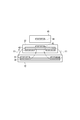
- FIG. 1 is a block diagram showing a configuration of a non-contact power feeding system according to an embodiment of the present invention.
- the contactless power supply system 101 receives a power supply device 100 that is provided on the ground side and transmits power and a power mounted on the vehicle 201 and transmitted from the power supply device 100. And it is comprised from the power receiving apparatus 200 (non-contact power receiving apparatus) which charges the battery 28.
- FIG. 1 is a block diagram showing a configuration of a non-contact power feeding system according to an embodiment of the present invention.
- the contactless power supply system 101 receives a power
- the power feeding device 100 is installed in a charging stand or the like having a parking space for the vehicle 201 and transmits power to the vehicle 201 in a contactless manner.
- the power supply apparatus 100 mainly includes a power control unit 11, a power transmission coil unit 12, a wireless communication unit 14, and a power transmission control unit 15. Furthermore, the camera 13 for photographing the vehicle 201 parked in the parking space from above the parking space is provided.
- the power control unit 11 has a function for converting AC power output from an AC power source 300 (for example, 50 Hz, 200 V) into high-frequency AC power and transmitting the power to the power transmission coil unit 12.
- the power control unit 11 includes a rectification unit 111, a PFC (Power Factor Correction) circuit 112, and an inverter 113.
- the rectifying unit 111 converts AC power output from the AC power supply 300 into DC power.
- the PFC circuit 112 includes a boost chopper circuit, for example, and is a circuit for improving the power factor by shaping the waveform of the output current from the rectifying unit 111.
- the output of the PFC circuit 112 is smoothed by a smoothing capacitor.
- the inverter 113 includes a plurality of switching elements (for example, IGBT), and converts DC power into AC power having a desired frequency by controlling on / off of each switching element.
- switching elements for example, IGBT
- the power transmission coil unit 12 is provided at a position facing the power reception coil unit 22 provided in the power reception device 200 when the vehicle 201 stops at a desired position in the parking space. Then, power is transmitted to the power receiving coil unit 22 in a non-contact manner. As shown in FIG. 2, the power transmission coil unit 12 includes a power transmission coil 31 and a ferrite plate 35 formed of a high magnetic permeability material and having a planar shape.
- the wireless communication unit 14 performs bidirectional communication with the wireless communication unit 24 provided in the power receiving apparatus 200. Through this communication, as will be described later, various types of data such as the output voltage Vinv, the output current Iinv of the inverter 113 detected by the power feeding device 100, the loss power WGC in the power transmission coil unit 12, and the coupling coefficient ⁇ described later are received by the power receiving device. 200.
- the power transmission control unit 15 comprehensively controls the entire power supply apparatus 100.
- the power transmission control unit 15 can be configured using, for example, a microcomputer mainly composed of a CPU, ROM, RAM, and I / O interface.
- the power transmission control unit 15 controls the power control unit 11, the wireless communication unit 14, and the camera 13.
- the power receiving device 200 mounted on the vehicle 201 includes a power receiving coil unit 22, a wireless communication unit 24, a charging control unit 25, a rectifying unit 26, a relay unit 27, and a temperature estimating unit 33.
- the battery 28 which stores electric power and supplies direct-current power to the inverter 29, and the notification part 37 which notifies the passenger
- the inverter 29 converts DC power into AC power and supplies the converted AC power to the motor 30.
- a front distance sensor 51 for measuring a distance from the front end portion to a wall surface 52 (see FIG. 7) provided in the parking space is provided at the front end portion of the vehicle 201.
- a gap sensor 61 for measuring the distance from the bottom to the power transmission coil unit 12 is provided at the bottom of the vehicle 201.
- an ultrasonic sensor can be used as the front distance sensor 51 and the gap sensor 61.
- the power receiving coil unit 22 is a coil for receiving the power transmitted from the power transmitting coil unit 12 in a non-contact manner. As shown in FIG. 2, the power receiving coil unit 22 includes a power transmission coil 31 and a ferrite plate 35 formed of a high magnetic permeability material and having a planar shape.
- the wireless communication unit 24 performs bidirectional communication with the wireless communication unit 14 provided in the power supply apparatus 100.
- the rectifying unit 26 is connected to the power receiving coil unit 22, converts the AC power output from the power receiving coil unit 22 into DC power, and outputs the DC power. As shown in FIG. 2, the rectifying unit 26 is mounted on a circuit board 44 inside an electric box 45 provided near the bottom surface of the vehicle 201.
- the relay unit 27 includes a relay switch that is turned on and off under the control of the charging control unit 25.
- the relay unit 27 can disconnect the circuit including the battery 28 and the circuit including the power receiving coil unit 22 and the rectifying unit 26 by turning off the relay switch.
- the temperature estimator 33 includes a power loss WJB of the circuit board 44 mounted inside the electric box 45 (see FIG. 2) on which the rectifier 26 is mounted, a power loss WVC in the power receiving coil unit 22, and a power loss in the power transmission coil unit 12.
- the ambient temperature of the power receiving coil section 22 power receiving coil ambient temperature
- the amount of heat generated due to the loss power WJB of the circuit board 44 and the loss power WVC in the power receiving coil unit 22 is the heat generation amount of the power receiving device.
- the notification unit 37 includes a display unit such as a display, and notifies the occupant of the vehicle 201 of various types of information including information related to non-contact power feeding.
- a display unit such as a display
- information related to non-contact power feeding includes a display unit such as a display, and notifies the occupant of the vehicle 201 of various types of information including information related to non-contact power feeding.
- the temperature estimation unit 33 estimates that the ambient temperature of the power receiving coil unit 22 exceeds the threshold temperature
- the fact is displayed on the display.
- the transmitted power from the power supply apparatus 100 is reduced (details will be described later), and accordingly, the time required for charging the battery 28 is changed. Displays this fact on the display and notifies the passenger.
- the charging control unit 25 controls the power receiving device 200 as a whole. In particular, information on the output voltage Vinv and output current Iinv of the inverter 113 transmitted from the power supply apparatus 100 via the wireless communication unit 24 is acquired. Further, the power loss WGC in the power transmission coil unit 12 is acquired. That is, the charge control unit 25 has a function as a power transmission side loss power acquisition unit that acquires the power loss of the power transmission coil unit 12.
- the charging control unit 25 receives the power receiving coil unit 22 for the power transmission coil unit 12 based on the distance to the wall surface 52 detected by the front distance sensor 51 and the distance to the power transmission coil unit 12 detected by the gap sensor 61.
- a function as a positional deviation amount acquisition unit that acquires the two-dimensional positional deviation amounts Lx and Ly and the gap G is provided.
- the charge control unit 25 and the temperature estimation unit 33 can be configured using, for example, a microcomputer mainly composed of a CPU, a ROM, a RAM, and an I / O interface.
- the ambient temperature of the receiving coil unit 22 when the ambient temperature of the receiving coil unit 22 reaches a preset threshold temperature during power transmission, the ambient temperature of the receiving coil unit 22 is abnormally overheated by reducing the transmitted power. To prevent.
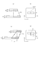
- FIG. 2 is an explanatory diagram showing magnetic flux generated between the power transmission coil unit 12 and the power reception coil unit 22.
- the power loss WJB in the electric box 45 is included.
- a circuit board 44 is disposed in the electric box 45, and various electronic components including the rectifying unit 26 are mounted on the circuit board 44. Accordingly, the circuit board 44 generates heat due to the lost power WJB generated during operation, and becomes a factor that increases the ambient temperature of the power receiving coil unit 22.
- ⁇ T A * WJB + B * WWC + C * WGC (1) Note that ⁇ T is the rising temperature after sufficient time has elapsed.
- the temperature rise ⁇ T is calculated, and further, the power receiving coil unit 22 is based on the ambient temperature detected by the ambient temperature sensor (not shown) provided at an appropriate position of the power supply apparatus 100 or the vehicle 201.
- the ambient temperature can be estimated. Specifically, the ambient temperature of the power receiving coil unit 22 can be obtained by adding the rising temperature ⁇ T to the ambient temperature.
- each loss power WJB, WVC, WGC is a copper loss and is proportional to the square of the current. Therefore, the current flowing in the circuit board 44 in the electric box 45, the circuit board 43 of the power receiving coil section 22 Can be calculated based on the current flowing in the circuit including the current and the current flowing in the power transmission coil unit 12.
- the correction coefficients A and B are known because they are unique numerical values in the power receiving device 200. Therefore, if the correction coefficient C of the lost power WGC in the power transmission coil unit 12 can be obtained, the rising temperature ⁇ T can be calculated from the above equation (1).
- the correction coefficient C is a numerical value that changes according to the relative positional relationship between the power transmission coil unit 12 and the power reception coil unit 22, and a calculation method will be described later.
- the power transmission coil unit 12 includes a ferrite plate 35 and a power transmission coil 31 wound around the upper surface of the ferrite plate 35.
- the power receiving coil section 22 includes a ferrite plate 42 and a power receiving coil 41 wound around the lower surface of the ferrite plate 42, and a circuit board 43 on which various electronic parts are mounted on the upper surface of the ferrite plate 42. Is provided.
- the power receiving coil unit 22 When the vehicle 201 stops at a desired position in the parking space, the power receiving coil unit 22 is installed at a position facing the power transmitting coil unit 12. Accordingly, when a current is supplied to the power transmission coil 31 and excited in this state, a magnetic flux is formed as shown by an arrow Y1. Since this magnetic flux passes through the ferrite plate 42 of the power receiving coil portion 22 and is linked to the power receiving coil 41, power is transmitted to the power receiving coil 41.
- the magnetic flux passing through the ferrite plate 42 changes according to the relative positional relationship between the power transmission coil unit 12 and the power reception coil unit 22. That is, when the vehicle 201 is not stopped at a desired position in the parking space, a planar positional deviation occurs between the power transmission coil unit 12 and the power reception coil unit 22. Furthermore, the distance (gap G) between the power transmission coil unit 12 and the power reception coil unit 22 changes according to the number of passengers riding on the vehicle 201. When such a positional shift occurs, the magnetic flux passing through the ferrite plate 42 changes and a high-density magnetic flux portion is generated, so that magnetic saturation occurs and causes heat generation. That is, the amount of heat generation changes according to the relative positional relationship between the power transmission coil unit 12 and the power reception coil unit 22.
- the magnetic flux passing through the ferrite plate 42 of the power receiving coil portion 22 changes according to the gap G between the power transmitting coil portion 12 and the power receiving coil portion 22.
- FIG. 3A shows the magnetic flux when the gap G, which is the distance between the power transmission coil unit 12 and the power receiving coil unit 22, is the reference value Ga
- FIG. 3B shows the gap G being the reference value.
- the magnetic flux when Gb is longer than Ga is shown.
- the magnetic flux reaching the power receiving coil portion 22 from the power transmitting coil portion 12 is reduced by increasing the gap G. That is, the magnetic flux indicated by the arrow Y12 is decreased with respect to the magnetic flux indicated by the arrow Y11. More specifically, the magnetic flux passing through the regions R21 and R22 shown in FIG. 3B is reduced with respect to the magnetic flux passing through the regions R11 and R12 shown in FIG.
- the correction coefficient C described above may be set so as to have a characteristic inversely proportional to the square of the gap G.
- FIG. 4A is a cross-sectional view in the X-axis direction when the power receiving coil unit 22 is not displaced with respect to the power transmitting coil unit 12, and an arrow Y13 indicates a magnetic flux.
- FIG. 4B schematically shows a plan view at this time.
- the receiving coil 41 has comprised rectangular shape, and let the short side direction be the X-axis direction among these.
- FIG. 4C is a cross-sectional view in the X-axis direction when a positional deviation occurs in the X-axis direction of the power receiving coil unit 22 by a distance L1, and an arrow Y14 indicates a magnetic flux.
- FIG. 4D schematically shows a plan view at this time.
- the positional deviation in the X-axis direction occurs between the power transmission coil unit 12 and the power reception coil unit 22, thereby coupling coefficient between the two coils. (This is indicated by “ ⁇ ”). Therefore, the power transmission control unit 15 of the power supply apparatus 100 increases the power supplied to the power transmission coil unit 12 so that desired power is generated in the power reception coil unit 22. As a result, as shown in FIG. 4C, the magnetic flux output from the power transmission coil 31 increases, and the magnetic flux passing through the ferrite plate 42 increases accordingly. For this reason, the magnetic flux is concentrated in the ferrite plate 42, which causes an increase in the ambient temperature of the power receiving coil portion 22. Further, the ambient temperature of the power receiving coil portion 22 increases linearly with respect to the amount of positional deviation in the X-axis direction.
- FIG. 5A is a cross-sectional view in the Y-axis direction when the power receiving coil unit 22 is not displaced with respect to the power transmitting coil unit 12, and an arrow Y15 indicates a magnetic flux.
- FIG. 5B schematically shows a plan view at this time.
- the receiving coil 41 has comprised the rectangular shape, and let the long side direction be the Y-axis direction among these.
- FIG. 5C is a cross-sectional view in the Y-axis direction in the case where a positional deviation has occurred in the Y-axis direction of the power receiving coil unit 22 by a distance L1, and an arrow Y16 indicates a magnetic flux.
- FIG. 5D schematically shows a plan view at this time.
- the positional deviation in the Y-axis direction occurs between the power transmission coil unit 12 and the power reception coil unit 22, thereby coupling coefficients between the two coils. ⁇ decreases. Therefore, the power transmission control unit 15 of the power supply apparatus 100 increases the power supplied to the power transmission coil unit 12 so that desired power is generated in the power reception coil unit 22.
- the magnetic flux output from the power transmission coil 31 increases, and accordingly, the magnetic flux passing through the ferrite plate 42 also increases. For this reason, the magnetic flux is concentrated in the ferrite plate 42, which causes an increase in the ambient temperature of the power receiving coil portion 22. Further, the ambient temperature of the power receiving coil portion 22 increases linearly with respect to the amount of positional deviation in the Y-axis direction.
- the positional deviation in the Y-axis direction has a greater influence on the temperature rise than the positional deviation in the X-axis direction described above. That is, in the case of the same shift amount, the amount of heat generation is greater when the shift is in the Y-axis direction (long-side direction) than in the X-axis direction (short-side direction). Therefore, as shown in FIG. 6, the correction coefficient C is set so as to change linearly with respect to the positional deviation amount in the X-axis direction (see the straight line Q3), and in the Y-axis direction (long side direction) What is necessary is just to set so that the correction coefficient C may change linearly with respect to the amount of positional deviation (see the straight line Q2). At this time, the straight line Q2 is set to have a larger inclination than the straight line Q3.
- the correction coefficient C is inversely proportional to the square of the gap G between the power transmission coil unit 12 and the power reception coil unit 22.
- the correction coefficient C changes linearly with respect to the positional deviation amount in the X-axis direction (referred to as “Lx”) and the positional deviation amount in the Y-axis direction (referred to as “Ly”). .
- the correction coefficient C is determined based on the above (A) and (B), the amount of heat generated due to the loss power WGC of the power transmission side coil can be corrected.
- the correction coefficient C can be obtained by the following equation (2) using the coefficients a, b, and c.
- C (a * Lx + b * Ly + c) / G 2 (2)
- the temperature estimation unit 33 shown in FIG. 1 calculates the correction coefficient C by obtaining the above-described positional deviation amounts Lx, Ly and the gap G, and substitutes this correction coefficient C into the above-described equation (1).
- the temperature rise ⁇ T is obtained by multiplying the power loss WGC of the power transmission coil 31. That is, the contribution of the temperature increase by the power transmission coil 31 is changed using the correction coefficient C that changes in accordance with the amount of positional deviation.
- the ambient temperature of the power receiving coil unit 22 is estimated by adding the above-described increase temperature ⁇ T to the ambient temperature of the power receiving coil unit 22, and when the estimated temperature reaches a preset threshold temperature, the transmitted power is Control to suppress further temperature rise.
- FIG. 7 is an explanatory diagram illustrating a first method for detecting the positional deviation amount Lx in the X-axis direction.
- an ultrasonic signal is transmitted from a front distance sensor 51 provided at the front end of the vehicle 201, and a distance L to a wall surface 52 provided at an appropriate location in the parking space is measured.
- the distance Lg (known numerical value) from the center point C2 of the power transmission coil unit 12 to the wall surface 52
- the distance Lv known numerical value
- the distance between the center points C1 and C2 that is, the shift amount Lx in the X-axis direction is calculated by the following equation (3).
- Lx Lg ⁇ Lv ⁇ L (3) In this way, the shift amount Lx in the X-axis direction can be obtained.
- FIG. 8 is an explanatory diagram showing a second method for detecting the positional deviation amount Lx in the X-axis direction and the positional deviation amount Ly in the Y-axis direction.
- the camera 201 provided in the power supply apparatus 100 is photographed from above with the vehicle 201 stopped in the parking frame 54 of the parking space. As a result, an overhead image as shown in FIG. 8 can be obtained.
- a planar positional deviation amount between the center point C2 of the power transmission coil unit 12 and the center point C1 of the power reception coil unit 22 is measured. Specifically, as shown in FIG. 8, it is possible to acquire the positional deviation amount Lx in the X-axis direction and the positional deviation amount Ly in the Y-axis direction.
- the gap G can be measured by transmitting an ultrasonic signal from the gap sensor 61 installed at the bottom of the vehicle 201 and receiving the reflected signal.
- the gap G can be obtained based on the coupling coefficient ⁇ between the power transmission coil 31 and the power reception coil 41 and the above-described positional shift amounts Lx and Ly.
- FIG. 10 is an equivalent circuit diagram of the power transmission coil unit 12 and the power reception coil unit 22, and the load RL corresponds to the battery 28 shown in FIG.
- JP2013-81275A between the voltage V generated in the power transmission coil 31, the current I flowing in the power transmission coil 31, and the coupling coefficient ⁇ of the power transmission coil 31 and the power reception coil 41, It is known that there is a relationship represented by the following formula (4).
- K1 to K7 are known numerical values.
- the coupling coefficient ⁇ can be obtained by measuring the voltage V generated in the power transmission coil 31 and the current I flowing in the power transmission coil 31.
- the coupling coefficient ⁇ is acquired by the charging control unit 25 through communication between the wireless communication unit 14 and the wireless communication unit 24. That is, the charge control unit 25 has a function as a coupling coefficient acquisition unit that acquires the coupling coefficient ⁇ between the power transmission coil 31 and the power reception coil 41.
- the gap G can be obtained.
- a map indicating the relationship between Lx, Ly, ⁇ and the gap G is set in a storage area (not shown) included in the temperature estimation unit 33, and the positional deviation amount Lx obtained by the above processing. By fitting, Ly and ⁇ to this map, the gap G can be determined.
- the correction coefficient C can be obtained based on the above-described equation (2).
- a correspondence map indicating the relationship between the positional deviation amounts Lx, Ly, the gap G, and the correction coefficient C is created in advance, and the correction coefficient C is calculated by substituting each numerical value into the correspondence map.
- FIG. 11 is a graph showing a change in the correction coefficient C obtained when an experiment for actually changing the positional deviation amounts Lx, Ly and the gap G is performed.
- FIG. 12 is an explanatory diagram showing the relative positional relationship between the power transmission coil 31 and the power reception coil 41, and the symbol q1 shown in FIG. 11 indicates that the center C1 of the power reception coil 41 is as shown in FIG. The state which has shifted
- the center C1 of the power receiving coil 41 is shown. Shows a state of being shifted by 100 mm in the negative direction of the X axis with respect to the center C2 of the power transmission coil 31.
- the correction coefficient C is 0.15, as indicated by the symbol q2 in FIG.
- the center C1 of the power receiving coil 41 is the power transmitting coil 31. This shows a state where the center C2 is displaced by 100 mm in the Y-axis direction. In this case, the correction coefficient C is 0.25 as indicated by the symbol q3 in FIG.
- the correction coefficient C can be obtained by applying the positional deviation amounts Lx, Ly and the gap G to a preset correspondence map. Further, based on the actually measured value of the correction coefficient C, the coefficients a, b, and c in the following equation (2) are obtained, and the correction coefficient C is calculated using these coefficients a, b, and c. Also good.
- C (a * Lx + b * Ly + c) / G 2 (2) By employing such a calculation method, the correction coefficient C can be calculated by a very simple method of substituting Lx, Ly, and G into the calculation formula.
- the flowchart shown in FIG. 13 shows processing by the temperature estimation unit 33 and processing by the power transmission control unit 15 shown in FIG.
- step a11 the temperature estimation unit 33 acquires data of the planar positional deviation amounts Lx and Ly of the power receiving coil unit 22 with respect to the power transmitting coil unit 12.
- the method shown in FIGS. 7 and 8 can be adopted.
- the temperature estimation unit 33 acquires the received power Pb, the received voltage Vb, and the current I2 flowing through the power receiving coil 41 in the power receiving coil unit 22. These data can be acquired from detection values of a voltmeter and an ammeter (not shown) provided in the power receiving coil unit 22.
- step b11 the power transmission control unit 15 measures the output voltage Vinv and the output current Iinv of the inverter 113, and transmits these data to the temperature estimation unit 33 through the wireless communication unit 14 and the wireless communication unit 24.
- step a13 the temperature estimation unit 33 calculates the respective power losses WJB, WVC, and WGC based on various data.
- each power loss is a copper loss, which is proportional to the square of the current, and can be calculated based on this relationship.
- step a14 the gap G between the power transmission coil unit 12 and the power reception coil unit 22 is calculated.
- the gap G can be obtained by employing the method shown in FIGS. 9 and 10 described above.
- step a15 the temperature estimation unit 33 obtains a correction coefficient C for correcting the loss power WGC. That is, since the positional deviation amounts Lx and Ly in the plane direction are acquired in the process of step a11 and the gap G is acquired in the process of step a14, the correction coefficient C is obtained using the above-described method based on this numerical value.
- step a16 the temperature estimation unit 33 calculates the rising temperature ⁇ T of the power receiving coil unit 22 by using the correction coefficient C obtained by the above processing and substituting it into the following equation (1).
- ⁇ T A * WJB + B * WWC + C * WGC (1)
- step a17 the temperature estimation unit 33 acquires the ambient temperature Ta of the vehicle 201, and adds the rising temperature ⁇ T to the ambient temperature Ta. Then, the rising temperature ⁇ T is controlled so that the following expression (5) is established. Ta + ⁇ T + Tm ⁇ (Allowable component temperature) (5) However, Tm is a margin.
- an allowable power Px that is an allowable value of power generated in the power receiving coil unit 22 is set so that the rising temperature ⁇ T becomes small, and the allowable power Px Data is transmitted to the power supply apparatus 100 via the wireless communication unit 24 and the wireless communication unit 14.
- step b12 the power transmission control unit 15 controls the power transmitted from the power transmission coil unit 12 so that the power generated in the power receiving coil unit 22 becomes the allowable power Px.
- the power transmission control unit 15 controls the power transmitted from the power transmission coil unit 12 so that the power generated in the power receiving coil unit 22 becomes the allowable power Px.
- the positional relationship between the power transmission coil 31 provided on the ground side and the power reception coil 41 provided on the vehicle 201 is shifted from the normal positional relationship.
- the contribution of the temperature increase due to the loss power WGC of the power transmission coil 31 is changed according to the magnitude of the positional deviation amount. Therefore, the ambient temperature of the power receiving coil unit 22 can be estimated with high accuracy without providing a temperature sensor for measuring the ambient temperature of the power receiving coil 41.
- power transmitted by the power supply apparatus 100 can be controlled so that the ambient temperature of the power receiving coil unit 22 does not rise to the component limit temperature, and an excessive temperature rise of the power receiving coil unit 22 and the surrounding electronic components is prevented. be able to.
- the charging time of the battery 28 becomes longer.
- the temperature estimation unit 33 controls the transmission power to be reduced, information indicating that the charging time has become longer is displayed on the notification unit 37 to notify the passenger of the vehicle 201.
- the temperature estimation unit 33 obtains a correction coefficient C based on the amount of positional deviation between the power transmission coil 31 and the power reception coil 41, and multiplies the loss power WGC of the power transmission coil 31 by the correction coefficient C, thereby The contribution of temperature rise due to power loss WGC is changed. Therefore, the ambient temperature of the power receiving coil unit 22 can be estimated with higher accuracy.
- planar positional deviation amounts X and Y and gap G which are positional deviation amounts between the power transmission coil 31 and the power receiving coil 41, are obtained, and the correction coefficient C is obtained based on these. Further, the loss coefficient WGC is multiplied by the correction coefficient C, and the temperature rise ⁇ T is obtained by (1) described above. Therefore, it is possible to estimate the ambient temperature of the power receiving coil unit 22 with higher accuracy.
- the coupling coefficient ⁇ between the power transmission coil 31 and the power receiving coil 41 is acquired, and the gap G is measured by acquiring the gap G based on the coupling coefficient ⁇ and the planar positional deviation amounts Lx and Ly. This eliminates the need for the gap sensor 61 for reducing the size of the apparatus.
- the correction coefficient C can be obtained with high accuracy, and as a result, the temperature increase ⁇ T can be estimated with high accuracy.
- the present invention is not limited to this, and the configuration of each part has the same function It can be replaced with any configuration having
Landscapes
- Engineering & Computer Science (AREA)
- Power Engineering (AREA)
- Transportation (AREA)
- Mechanical Engineering (AREA)
- Computer Networks & Wireless Communication (AREA)
- General Physics & Mathematics (AREA)
- Physics & Mathematics (AREA)
- Life Sciences & Earth Sciences (AREA)
- Sustainable Development (AREA)
- Sustainable Energy (AREA)
- Charge And Discharge Circuits For Batteries Or The Like (AREA)
- Electric Propulsion And Braking For Vehicles (AREA)
- Current-Collector Devices For Electrically Propelled Vehicles (AREA)
Priority Applications (9)
| Application Number | Priority Date | Filing Date | Title |
|---|---|---|---|
| EP15888434.6A EP3282554B1 (en) | 2015-04-07 | 2015-04-07 | Temperature estimation device and temperature estimation method for contactless power-reception device |
| JP2017510825A JP6424952B2 (ja) | 2015-04-07 | 2015-04-07 | 非接触受電装置の温度推定装置及び温度推定方法 |
| MX2017012586A MX360378B (es) | 2015-04-07 | 2015-04-07 | Dispositivo de estimacion de temperatura y metodo de estimacion de temperatura para dispositivo de recepcion de energia sin contacto. |
| RU2017134746A RU2657705C1 (ru) | 2015-04-07 | 2015-04-07 | Устройство оценки температуры и способ оценки температуры для бесконтактного устройства приема мощности |
| CN201580078378.6A CN107580742B (zh) | 2015-04-07 | 2015-04-07 | 非接触受电装置的温度估计装置和温度估计方法 |
| CA2981692A CA2981692C (en) | 2015-04-07 | 2015-04-07 | Temperature estimation device and temperature estimation method for contactless power-reception device |
| PCT/JP2015/060814 WO2016162940A1 (ja) | 2015-04-07 | 2015-04-07 | 非接触受電装置の温度推定装置及び温度推定方法 |
| US15/564,283 US10180361B2 (en) | 2015-04-07 | 2015-04-07 | Temperature estimation device and temperature estimation method for contactless power-reception device |
| KR1020177030910A KR101821104B1 (ko) | 2015-04-07 | 2015-04-07 | 비접촉 수전 장치의 온도 추정 장치 및 온도 추정 방법 |
Applications Claiming Priority (1)
| Application Number | Priority Date | Filing Date | Title |
|---|---|---|---|
| PCT/JP2015/060814 WO2016162940A1 (ja) | 2015-04-07 | 2015-04-07 | 非接触受電装置の温度推定装置及び温度推定方法 |
Publications (1)
| Publication Number | Publication Date |
|---|---|
| WO2016162940A1 true WO2016162940A1 (ja) | 2016-10-13 |
Family
ID=57072524
Family Applications (1)
| Application Number | Title | Priority Date | Filing Date |
|---|---|---|---|
| PCT/JP2015/060814 WO2016162940A1 (ja) | 2015-04-07 | 2015-04-07 | 非接触受電装置の温度推定装置及び温度推定方法 |
Country Status (9)
| Country | Link |
|---|---|
| US (1) | US10180361B2 (ko) |
| EP (1) | EP3282554B1 (ko) |
| JP (1) | JP6424952B2 (ko) |
| KR (1) | KR101821104B1 (ko) |
| CN (1) | CN107580742B (ko) |
| CA (1) | CA2981692C (ko) |
| MX (1) | MX360378B (ko) |
| RU (1) | RU2657705C1 (ko) |
| WO (1) | WO2016162940A1 (ko) |
Cited By (4)
| Publication number | Priority date | Publication date | Assignee | Title |
|---|---|---|---|---|
| JP2018207656A (ja) * | 2017-06-02 | 2018-12-27 | 日産自動車株式会社 | 非接触給電システムによる異物検知方法及び非接触給電システム |
| WO2019180895A1 (ja) * | 2018-03-22 | 2019-09-26 | マクセル株式会社 | 非接触送電装置および非接触送受電システム |
| JP2020054179A (ja) * | 2018-09-28 | 2020-04-02 | オムロン株式会社 | 電源装置および電源システム |
| US20210323428A1 (en) * | 2018-10-05 | 2021-10-21 | Ihi Corporation | Misalignment detection device and coil device |
Families Citing this family (7)
| Publication number | Priority date | Publication date | Assignee | Title |
|---|---|---|---|---|
| DE102015217274A1 (de) * | 2015-09-10 | 2017-03-16 | Robert Bosch Gmbh | Verfahren zur induktiven Energieübertragung und Vorrichtung zum Betrieb einer induktiven Energieübertragungsvorrichtung |
| JP7027127B2 (ja) * | 2017-11-06 | 2022-03-01 | キヤノン株式会社 | 携帯型装置、制御方法及びプログラム |
| TWI745800B (zh) | 2018-12-21 | 2021-11-11 | 美商米沃奇電子工具公司 | 電池組充電器、控制電池組充電器之操作的方法及用於電池組充電器之充電電路 |
| CN109921494B (zh) * | 2019-04-04 | 2021-04-27 | 北京品驰医疗设备有限公司 | 植入医疗设备及其充电控制方法 |
| KR20210129855A (ko) * | 2020-04-21 | 2021-10-29 | 현대자동차주식회사 | 무선 충전 장치, 차량용 무선 충전 시스템 및 그 제어 방법 |
| US12042043B2 (en) | 2020-06-11 | 2024-07-23 | Kohler Co. | Temperature tracking mirror |
| CN115575884B (zh) * | 2022-11-08 | 2023-03-10 | 国网湖北省电力有限公司营销服务中心(计量中心) | 充电站内充电桩充电量对齐及计量误差计算方法 |
Citations (3)
| Publication number | Priority date | Publication date | Assignee | Title |
|---|---|---|---|---|
| JP2013135572A (ja) * | 2011-12-27 | 2013-07-08 | Toyota Motor Corp | 非接触受電装置および非接触充電システム |
| JP2013192411A (ja) * | 2012-03-15 | 2013-09-26 | Denso Corp | 異物検出装置および非接触電力授受システム |
| US20140084856A1 (en) * | 2012-09-25 | 2014-03-27 | Motorola Mobility Llc | Methods and systems for rapid wireless charging |
Family Cites Families (21)
| Publication number | Priority date | Publication date | Assignee | Title |
|---|---|---|---|---|
| DE59309309D1 (de) * | 1993-07-27 | 1999-02-25 | Siemens Ag | Schaltungsanordnung zum Ermitteln der Temperatur einer stromgeregelten elektrischen Spule |
| JPH07334263A (ja) | 1994-06-06 | 1995-12-22 | Fujitsu Ltd | 温度制御装置 |
| JP3644354B2 (ja) * | 2000-05-09 | 2005-04-27 | トヨタ自動車株式会社 | 温度推定方法および装置 |
| US7071649B2 (en) * | 2001-08-17 | 2006-07-04 | Delphi Technologies, Inc. | Active temperature estimation for electric machines |
| JP4501433B2 (ja) * | 2003-10-24 | 2010-07-14 | ダイキン工業株式会社 | Dcモータのコイル温度推定方法およびその装置 |
| EP1799013B1 (en) * | 2005-12-14 | 2010-02-17 | Harman/Becker Automotive Systems GmbH | Method and system for predicting the behavior of a transducer |
| JP2010022183A (ja) | 2008-02-08 | 2010-01-28 | Suri-Ai:Kk | 電気自動車及びそれに好適な車両用誘導送電装置 |
| JP5658592B2 (ja) * | 2011-02-21 | 2015-01-28 | 国立大学法人埼玉大学 | 移動体用非接触給電装置 |
| JP2012244763A (ja) * | 2011-05-19 | 2012-12-10 | Sony Corp | 給電装置、給電システムおよび電子機器 |
| DE102011107375B4 (de) * | 2011-07-14 | 2013-02-21 | Maschinenfabrik Reinhausen Gmbh | Einrichtung zur Nachbildung und Anzeige der Wicklungstemperatur eines elektrischen Leistungstransformators und dazu geeignete Begrenzungsschaltung |
| US9417199B2 (en) * | 2012-01-17 | 2016-08-16 | Triune Systems, LLC | Method and system of wireless power transfer foreign object detection |
| RU124852U1 (ru) * | 2012-07-19 | 2013-02-10 | Александр Викторович Атаманов | Беспроводная зарядная система для маломощных потребителей электрической энергии |
| WO2014041655A1 (ja) * | 2012-09-13 | 2014-03-20 | トヨタ自動車株式会社 | 非接触給電システム、ならびにそれに用いられる送電装置および車両 |
| JP6002513B2 (ja) * | 2012-09-14 | 2016-10-05 | ソニー株式会社 | 非接触給電システム、端末装置および非接触給電方法 |
| JP5607698B2 (ja) * | 2012-10-18 | 2014-10-15 | ファナック株式会社 | 電動機の温度を推定する温度推定装置 |
| US9768643B2 (en) * | 2012-11-02 | 2017-09-19 | Panasonic Intellectual Property Management Co., Ltd. | Wireless power transmission system capable of continuing power transmission while suppressing heatup of foreign objects |
| FR3002036A1 (fr) * | 2013-02-14 | 2014-08-15 | Hispano Suiza Sa | Mesure de la temperature homogene d'un bobinage par augmentation de la resistance d'un fil |
| JP2016524130A (ja) * | 2013-05-03 | 2016-08-12 | スリーエム イノベイティブ プロパティズ カンパニー | 電気導体の温度監視システム |
| US9341520B2 (en) * | 2013-06-16 | 2016-05-17 | Qualcomm Incorporated | System and method for estimating ambient temperature of a portable computing device using a voice coil |
| JP6147112B2 (ja) * | 2013-06-25 | 2017-06-14 | ローム株式会社 | ワイヤレス送電装置およびその制御方法 |
| JP6123607B2 (ja) | 2013-09-24 | 2017-05-10 | トヨタ自動車株式会社 | 車両 |
-
2015
- 2015-04-07 CN CN201580078378.6A patent/CN107580742B/zh active Active
- 2015-04-07 MX MX2017012586A patent/MX360378B/es active IP Right Grant
- 2015-04-07 US US15/564,283 patent/US10180361B2/en active Active
- 2015-04-07 JP JP2017510825A patent/JP6424952B2/ja active Active
- 2015-04-07 CA CA2981692A patent/CA2981692C/en active Active
- 2015-04-07 RU RU2017134746A patent/RU2657705C1/ru active
- 2015-04-07 EP EP15888434.6A patent/EP3282554B1/en active Active
- 2015-04-07 KR KR1020177030910A patent/KR101821104B1/ko active IP Right Grant
- 2015-04-07 WO PCT/JP2015/060814 patent/WO2016162940A1/ja active Application Filing
Patent Citations (3)
| Publication number | Priority date | Publication date | Assignee | Title |
|---|---|---|---|---|
| JP2013135572A (ja) * | 2011-12-27 | 2013-07-08 | Toyota Motor Corp | 非接触受電装置および非接触充電システム |
| JP2013192411A (ja) * | 2012-03-15 | 2013-09-26 | Denso Corp | 異物検出装置および非接触電力授受システム |
| US20140084856A1 (en) * | 2012-09-25 | 2014-03-27 | Motorola Mobility Llc | Methods and systems for rapid wireless charging |
Non-Patent Citations (1)
| Title |
|---|
| See also references of EP3282554A4 * |
Cited By (11)
| Publication number | Priority date | Publication date | Assignee | Title |
|---|---|---|---|---|
| JP2018207656A (ja) * | 2017-06-02 | 2018-12-27 | 日産自動車株式会社 | 非接触給電システムによる異物検知方法及び非接触給電システム |
| WO2019180895A1 (ja) * | 2018-03-22 | 2019-09-26 | マクセル株式会社 | 非接触送電装置および非接触送受電システム |
| JPWO2019180895A1 (ja) * | 2018-03-22 | 2020-09-10 | マクセル株式会社 | 非接触送電装置および非接触送受電システム |
| JP7003221B2 (ja) | 2018-03-22 | 2022-01-20 | マクセル株式会社 | 非接触送電装置および非接触送受電システム |
| US11552506B2 (en) | 2018-03-22 | 2023-01-10 | Maxell, Ltd. | Non-contact power transmission device and non-contact power transmission/reception system |
| US12074458B2 (en) | 2018-03-22 | 2024-08-27 | Maxell, Ltd. | Non-contact power transmission device and non-contact power transmission/reception system |
| JP2020054179A (ja) * | 2018-09-28 | 2020-04-02 | オムロン株式会社 | 電源装置および電源システム |
| WO2020066134A1 (ja) * | 2018-09-28 | 2020-04-02 | オムロン株式会社 | 電源装置および電源システム |
| US11916473B2 (en) | 2018-09-28 | 2024-02-27 | Omron Corporation | Power supply device and power supply system |
| US20210323428A1 (en) * | 2018-10-05 | 2021-10-21 | Ihi Corporation | Misalignment detection device and coil device |
| US11912149B2 (en) * | 2018-10-05 | 2024-02-27 | Ihi Corporation | Misalignment detection device and coil device |
Also Published As
| Publication number | Publication date |
|---|---|
| KR101821104B1 (ko) | 2018-01-22 |
| CN107580742A (zh) | 2018-01-12 |
| US10180361B2 (en) | 2019-01-15 |
| CN107580742B (zh) | 2019-01-18 |
| US20180136048A1 (en) | 2018-05-17 |
| EP3282554A1 (en) | 2018-02-14 |
| KR20170130589A (ko) | 2017-11-28 |
| CA2981692A1 (en) | 2016-10-13 |
| EP3282554B1 (en) | 2019-01-09 |
| CA2981692C (en) | 2018-09-04 |
| RU2657705C1 (ru) | 2018-06-14 |
| EP3282554A4 (en) | 2018-03-21 |
| MX360378B (es) | 2018-10-31 |
| JPWO2016162940A1 (ja) | 2018-02-01 |
| JP6424952B2 (ja) | 2018-11-21 |
| MX2017012586A (es) | 2018-01-09 |
Similar Documents
| Publication | Publication Date | Title |
|---|---|---|
| WO2016162940A1 (ja) | 非接触受電装置の温度推定装置及び温度推定方法 | |
| JP6036995B2 (ja) | 非接触給電システム | |
| JP5524724B2 (ja) | 車両用給電装置 | |
| US10008883B2 (en) | Noise reducing power feed device, power reception device and power feed method | |
| JP6103070B2 (ja) | 非接触給電システム及び送電装置 | |
| JP2015008548A (ja) | 非接触電力伝送装置 | |
| CA2974480C (en) | Parking assistance device and parking assistance method | |
| US11254226B2 (en) | Coil position detecting method for non-contact power supply system, and non-contact power supply system | |
| US9887559B2 (en) | Power feeding device and power receiving device for contactless power transmission | |
| JP6977654B2 (ja) | ワイヤレス受電装置、及びワイヤレス電力伝送システム | |
| WO2017130688A1 (ja) | 非接触給電システム | |
| EP3836349B1 (en) | Contactless power transmission system | |
| JP6252433B2 (ja) | 非接触送受電システム | |
| JP5757269B2 (ja) | 非接触給電装置 | |
| JP2017017771A (ja) | 非接触送電装置 | |
| WO2017130690A1 (ja) | 非接触給電システム | |
| US11515730B2 (en) | Contactless power transmission system for transmitting power from power transmitter apparatus to power receiver apparatus, and supplying load device with desired voltage | |
| JP6805728B2 (ja) | 通電制御システム | |
| JP2014121101A (ja) | 非接触給電装置 | |
| US10097130B2 (en) | Energization control system and sensor unit | |
| JP2007049781A (ja) | 非接触給電システム |
Legal Events
| Date | Code | Title | Description |
|---|---|---|---|
| 121 | Ep: the epo has been informed by wipo that ep was designated in this application |
Ref document number: 15888434 Country of ref document: EP Kind code of ref document: A1 |
|
| ENP | Entry into the national phase |
Ref document number: 2017510825 Country of ref document: JP Kind code of ref document: A |
|
| REEP | Request for entry into the european phase |
Ref document number: 2015888434 Country of ref document: EP |
|
| WWE | Wipo information: entry into national phase |
Ref document number: MX/A/2017/012586 Country of ref document: MX |
|
| ENP | Entry into the national phase |
Ref document number: 2981692 Country of ref document: CA |
|
| WWE | Wipo information: entry into national phase |
Ref document number: 2017134746 Country of ref document: RU Ref document number: 15564283 Country of ref document: US |
|
| NENP | Non-entry into the national phase |
Ref country code: DE |
|
| ENP | Entry into the national phase |
Ref document number: 20177030910 Country of ref document: KR Kind code of ref document: A |