EP3282554A1 - Temperature estimation device and temperature estimation method for contactless power-reception device - Google Patents
Temperature estimation device and temperature estimation method for contactless power-reception device Download PDFInfo
- Publication number
- EP3282554A1 EP3282554A1 EP15888434.6A EP15888434A EP3282554A1 EP 3282554 A1 EP3282554 A1 EP 3282554A1 EP 15888434 A EP15888434 A EP 15888434A EP 3282554 A1 EP3282554 A1 EP 3282554A1
- Authority
- EP
- European Patent Office
- Prior art keywords
- power
- power reception
- power transmission
- transmission coil
- positional shift
- Prior art date
- Legal status (The legal status is an assumption and is not a legal conclusion. Google has not performed a legal analysis and makes no representation as to the accuracy of the status listed.)
- Granted
Links
- 238000000034 method Methods 0.000 title claims description 20
- 230000005540 biological transmission Effects 0.000 claims abstract description 137
- 230000020169 heat generation Effects 0.000 claims abstract description 13
- 238000012937 correction Methods 0.000 claims description 53
- 230000008878 coupling Effects 0.000 claims description 16
- 238000010168 coupling process Methods 0.000 claims description 16
- 238000005859 coupling reaction Methods 0.000 claims description 16
- 238000004891 communication Methods 0.000 abstract description 21
- 230000002159 abnormal effect Effects 0.000 abstract 1
- 230000004907 flux Effects 0.000 description 32
- 229910000859 α-Fe Inorganic materials 0.000 description 21
- 238000012545 processing Methods 0.000 description 11
- 230000007423 decrease Effects 0.000 description 8
- 238000004364 calculation method Methods 0.000 description 5
- 230000006870 function Effects 0.000 description 5
- 238000010586 diagram Methods 0.000 description 4
- RYGMFSIKBFXOCR-UHFFFAOYSA-N Copper Chemical compound [Cu] RYGMFSIKBFXOCR-UHFFFAOYSA-N 0.000 description 3
- 230000008859 change Effects 0.000 description 3
- 240000004050 Pentaglottis sempervirens Species 0.000 description 2
- 235000004522 Pentaglottis sempervirens Nutrition 0.000 description 2
- 238000013459 approach Methods 0.000 description 2
- 229910052802 copper Inorganic materials 0.000 description 2
- 239000010949 copper Substances 0.000 description 2
- 239000000463 material Substances 0.000 description 2
- 230000035699 permeability Effects 0.000 description 2
- 239000003990 capacitor Substances 0.000 description 1
- 238000001514 detection method Methods 0.000 description 1
- 230000005674 electromagnetic induction Effects 0.000 description 1
- 230000005284 excitation Effects 0.000 description 1
- 238000002474 experimental method Methods 0.000 description 1
- 238000009499 grossing Methods 0.000 description 1
- 238000005259 measurement Methods 0.000 description 1
- 230000000630 rising effect Effects 0.000 description 1
- 238000007493 shaping process Methods 0.000 description 1
Images


Classifications
-
- B—PERFORMING OPERATIONS; TRANSPORTING
- B60—VEHICLES IN GENERAL
- B60L—PROPULSION OF ELECTRICALLY-PROPELLED VEHICLES; SUPPLYING ELECTRIC POWER FOR AUXILIARY EQUIPMENT OF ELECTRICALLY-PROPELLED VEHICLES; ELECTRODYNAMIC BRAKE SYSTEMS FOR VEHICLES IN GENERAL; MAGNETIC SUSPENSION OR LEVITATION FOR VEHICLES; MONITORING OPERATING VARIABLES OF ELECTRICALLY-PROPELLED VEHICLES; ELECTRIC SAFETY DEVICES FOR ELECTRICALLY-PROPELLED VEHICLES
- B60L53/00—Methods of charging batteries, specially adapted for electric vehicles; Charging stations or on-board charging equipment therefor; Exchange of energy storage elements in electric vehicles
- B60L53/10—Methods of charging batteries, specially adapted for electric vehicles; Charging stations or on-board charging equipment therefor; Exchange of energy storage elements in electric vehicles characterised by the energy transfer between the charging station and the vehicle
- B60L53/12—Inductive energy transfer
-
- B—PERFORMING OPERATIONS; TRANSPORTING
- B60—VEHICLES IN GENERAL
- B60L—PROPULSION OF ELECTRICALLY-PROPELLED VEHICLES; SUPPLYING ELECTRIC POWER FOR AUXILIARY EQUIPMENT OF ELECTRICALLY-PROPELLED VEHICLES; ELECTRODYNAMIC BRAKE SYSTEMS FOR VEHICLES IN GENERAL; MAGNETIC SUSPENSION OR LEVITATION FOR VEHICLES; MONITORING OPERATING VARIABLES OF ELECTRICALLY-PROPELLED VEHICLES; ELECTRIC SAFETY DEVICES FOR ELECTRICALLY-PROPELLED VEHICLES
- B60L3/00—Electric devices on electrically-propelled vehicles for safety purposes; Monitoring operating variables, e.g. speed, deceleration or energy consumption
-
- B—PERFORMING OPERATIONS; TRANSPORTING
- B60—VEHICLES IN GENERAL
- B60L—PROPULSION OF ELECTRICALLY-PROPELLED VEHICLES; SUPPLYING ELECTRIC POWER FOR AUXILIARY EQUIPMENT OF ELECTRICALLY-PROPELLED VEHICLES; ELECTRODYNAMIC BRAKE SYSTEMS FOR VEHICLES IN GENERAL; MAGNETIC SUSPENSION OR LEVITATION FOR VEHICLES; MONITORING OPERATING VARIABLES OF ELECTRICALLY-PROPELLED VEHICLES; ELECTRIC SAFETY DEVICES FOR ELECTRICALLY-PROPELLED VEHICLES
- B60L50/00—Electric propulsion with power supplied within the vehicle
- B60L50/30—Electric propulsion with power supplied within the vehicle using propulsion power stored mechanically, e.g. in fly-wheels
-
- B—PERFORMING OPERATIONS; TRANSPORTING
- B60—VEHICLES IN GENERAL
- B60L—PROPULSION OF ELECTRICALLY-PROPELLED VEHICLES; SUPPLYING ELECTRIC POWER FOR AUXILIARY EQUIPMENT OF ELECTRICALLY-PROPELLED VEHICLES; ELECTRODYNAMIC BRAKE SYSTEMS FOR VEHICLES IN GENERAL; MAGNETIC SUSPENSION OR LEVITATION FOR VEHICLES; MONITORING OPERATING VARIABLES OF ELECTRICALLY-PROPELLED VEHICLES; ELECTRIC SAFETY DEVICES FOR ELECTRICALLY-PROPELLED VEHICLES
- B60L53/00—Methods of charging batteries, specially adapted for electric vehicles; Charging stations or on-board charging equipment therefor; Exchange of energy storage elements in electric vehicles
- B60L53/30—Constructional details of charging stations
- B60L53/35—Means for automatic or assisted adjustment of the relative position of charging devices and vehicles
- B60L53/36—Means for automatic or assisted adjustment of the relative position of charging devices and vehicles by positioning the vehicle
-
- B—PERFORMING OPERATIONS; TRANSPORTING
- B60—VEHICLES IN GENERAL
- B60L—PROPULSION OF ELECTRICALLY-PROPELLED VEHICLES; SUPPLYING ELECTRIC POWER FOR AUXILIARY EQUIPMENT OF ELECTRICALLY-PROPELLED VEHICLES; ELECTRODYNAMIC BRAKE SYSTEMS FOR VEHICLES IN GENERAL; MAGNETIC SUSPENSION OR LEVITATION FOR VEHICLES; MONITORING OPERATING VARIABLES OF ELECTRICALLY-PROPELLED VEHICLES; ELECTRIC SAFETY DEVICES FOR ELECTRICALLY-PROPELLED VEHICLES
- B60L53/00—Methods of charging batteries, specially adapted for electric vehicles; Charging stations or on-board charging equipment therefor; Exchange of energy storage elements in electric vehicles
- B60L53/30—Constructional details of charging stations
- B60L53/35—Means for automatic or assisted adjustment of the relative position of charging devices and vehicles
- B60L53/38—Means for automatic or assisted adjustment of the relative position of charging devices and vehicles specially adapted for charging by inductive energy transfer
-
- G—PHYSICS
- G01—MEASURING; TESTING
- G01K—MEASURING TEMPERATURE; MEASURING QUANTITY OF HEAT; THERMALLY-SENSITIVE ELEMENTS NOT OTHERWISE PROVIDED FOR
- G01K1/00—Details of thermometers not specially adapted for particular types of thermometer
- G01K1/14—Supports; Fastening devices; Arrangements for mounting thermometers in particular locations
-
- G—PHYSICS
- G01—MEASURING; TESTING
- G01K—MEASURING TEMPERATURE; MEASURING QUANTITY OF HEAT; THERMALLY-SENSITIVE ELEMENTS NOT OTHERWISE PROVIDED FOR
- G01K3/00—Thermometers giving results other than momentary value of temperature
- G01K3/005—Circuits arrangements for indicating a predetermined temperature
-
- G—PHYSICS
- G01—MEASURING; TESTING
- G01K—MEASURING TEMPERATURE; MEASURING QUANTITY OF HEAT; THERMALLY-SENSITIVE ELEMENTS NOT OTHERWISE PROVIDED FOR
- G01K3/00—Thermometers giving results other than momentary value of temperature
- G01K3/08—Thermometers giving results other than momentary value of temperature giving differences of values; giving differentiated values
- G01K3/10—Thermometers giving results other than momentary value of temperature giving differences of values; giving differentiated values in respect of time, e.g. reacting only to a quick change of temperature
-
- G—PHYSICS
- G01—MEASURING; TESTING
- G01R—MEASURING ELECTRIC VARIABLES; MEASURING MAGNETIC VARIABLES
- G01R21/00—Arrangements for measuring electric power or power factor
-
- H—ELECTRICITY
- H01—ELECTRIC ELEMENTS
- H01F—MAGNETS; INDUCTANCES; TRANSFORMERS; SELECTION OF MATERIALS FOR THEIR MAGNETIC PROPERTIES
- H01F38/00—Adaptations of transformers or inductances for specific applications or functions
- H01F38/14—Inductive couplings
-
- H—ELECTRICITY
- H02—GENERATION; CONVERSION OR DISTRIBUTION OF ELECTRIC POWER
- H02J—CIRCUIT ARRANGEMENTS OR SYSTEMS FOR SUPPLYING OR DISTRIBUTING ELECTRIC POWER; SYSTEMS FOR STORING ELECTRIC ENERGY
- H02J50/00—Circuit arrangements or systems for wireless supply or distribution of electric power
- H02J50/10—Circuit arrangements or systems for wireless supply or distribution of electric power using inductive coupling
- H02J50/12—Circuit arrangements or systems for wireless supply or distribution of electric power using inductive coupling of the resonant type
-
- H—ELECTRICITY
- H02—GENERATION; CONVERSION OR DISTRIBUTION OF ELECTRIC POWER
- H02J—CIRCUIT ARRANGEMENTS OR SYSTEMS FOR SUPPLYING OR DISTRIBUTING ELECTRIC POWER; SYSTEMS FOR STORING ELECTRIC ENERGY
- H02J50/00—Circuit arrangements or systems for wireless supply or distribution of electric power
- H02J50/80—Circuit arrangements or systems for wireless supply or distribution of electric power involving the exchange of data, concerning supply or distribution of electric power, between transmitting devices and receiving devices
-
- H—ELECTRICITY
- H02—GENERATION; CONVERSION OR DISTRIBUTION OF ELECTRIC POWER
- H02J—CIRCUIT ARRANGEMENTS OR SYSTEMS FOR SUPPLYING OR DISTRIBUTING ELECTRIC POWER; SYSTEMS FOR STORING ELECTRIC ENERGY
- H02J50/00—Circuit arrangements or systems for wireless supply or distribution of electric power
- H02J50/90—Circuit arrangements or systems for wireless supply or distribution of electric power involving detection or optimisation of position, e.g. alignment
-
- H02J7/0026—
-
- H02J7/0027—
-
- H—ELECTRICITY
- H02—GENERATION; CONVERSION OR DISTRIBUTION OF ELECTRIC POWER
- H02J—CIRCUIT ARRANGEMENTS OR SYSTEMS FOR SUPPLYING OR DISTRIBUTING ELECTRIC POWER; SYSTEMS FOR STORING ELECTRIC ENERGY
- H02J7/00—Circuit arrangements for charging or depolarising batteries or for supplying loads from batteries
- H02J7/0029—Circuit arrangements for charging or depolarising batteries or for supplying loads from batteries with safety or protection devices or circuits
- H02J7/00309—Overheat or overtemperature protection
-
- H02J7/025—
-
- B—PERFORMING OPERATIONS; TRANSPORTING
- B60—VEHICLES IN GENERAL
- B60L—PROPULSION OF ELECTRICALLY-PROPELLED VEHICLES; SUPPLYING ELECTRIC POWER FOR AUXILIARY EQUIPMENT OF ELECTRICALLY-PROPELLED VEHICLES; ELECTRODYNAMIC BRAKE SYSTEMS FOR VEHICLES IN GENERAL; MAGNETIC SUSPENSION OR LEVITATION FOR VEHICLES; MONITORING OPERATING VARIABLES OF ELECTRICALLY-PROPELLED VEHICLES; ELECTRIC SAFETY DEVICES FOR ELECTRICALLY-PROPELLED VEHICLES
- B60L2240/00—Control parameters of input or output; Target parameters
- B60L2240/10—Vehicle control parameters
- B60L2240/36—Temperature of vehicle components or parts
-
- B—PERFORMING OPERATIONS; TRANSPORTING
- B60—VEHICLES IN GENERAL
- B60L—PROPULSION OF ELECTRICALLY-PROPELLED VEHICLES; SUPPLYING ELECTRIC POWER FOR AUXILIARY EQUIPMENT OF ELECTRICALLY-PROPELLED VEHICLES; ELECTRODYNAMIC BRAKE SYSTEMS FOR VEHICLES IN GENERAL; MAGNETIC SUSPENSION OR LEVITATION FOR VEHICLES; MONITORING OPERATING VARIABLES OF ELECTRICALLY-PROPELLED VEHICLES; ELECTRIC SAFETY DEVICES FOR ELECTRICALLY-PROPELLED VEHICLES
- B60L2260/00—Operating Modes
- B60L2260/40—Control modes
- B60L2260/44—Control modes by parameter estimation
-
- G—PHYSICS
- G01—MEASURING; TESTING
- G01K—MEASURING TEMPERATURE; MEASURING QUANTITY OF HEAT; THERMALLY-SENSITIVE ELEMENTS NOT OTHERWISE PROVIDED FOR
- G01K2205/00—Application of thermometers in motors, e.g. of a vehicle
-
- H—ELECTRICITY
- H02—GENERATION; CONVERSION OR DISTRIBUTION OF ELECTRIC POWER
- H02J—CIRCUIT ARRANGEMENTS OR SYSTEMS FOR SUPPLYING OR DISTRIBUTING ELECTRIC POWER; SYSTEMS FOR STORING ELECTRIC ENERGY
- H02J2310/00—The network for supplying or distributing electric power characterised by its spatial reach or by the load
- H02J2310/40—The network being an on-board power network, i.e. within a vehicle
- H02J2310/48—The network being an on-board power network, i.e. within a vehicle for electric vehicles [EV] or hybrid vehicles [HEV]
-
- Y—GENERAL TAGGING OF NEW TECHNOLOGICAL DEVELOPMENTS; GENERAL TAGGING OF CROSS-SECTIONAL TECHNOLOGIES SPANNING OVER SEVERAL SECTIONS OF THE IPC; TECHNICAL SUBJECTS COVERED BY FORMER USPC CROSS-REFERENCE ART COLLECTIONS [XRACs] AND DIGESTS
- Y02—TECHNOLOGIES OR APPLICATIONS FOR MITIGATION OR ADAPTATION AGAINST CLIMATE CHANGE
- Y02T—CLIMATE CHANGE MITIGATION TECHNOLOGIES RELATED TO TRANSPORTATION
- Y02T10/00—Road transport of goods or passengers
- Y02T10/60—Other road transportation technologies with climate change mitigation effect
- Y02T10/70—Energy storage systems for electromobility, e.g. batteries
-
- Y—GENERAL TAGGING OF NEW TECHNOLOGICAL DEVELOPMENTS; GENERAL TAGGING OF CROSS-SECTIONAL TECHNOLOGIES SPANNING OVER SEVERAL SECTIONS OF THE IPC; TECHNICAL SUBJECTS COVERED BY FORMER USPC CROSS-REFERENCE ART COLLECTIONS [XRACs] AND DIGESTS
- Y02—TECHNOLOGIES OR APPLICATIONS FOR MITIGATION OR ADAPTATION AGAINST CLIMATE CHANGE
- Y02T—CLIMATE CHANGE MITIGATION TECHNOLOGIES RELATED TO TRANSPORTATION
- Y02T10/00—Road transport of goods or passengers
- Y02T10/60—Other road transportation technologies with climate change mitigation effect
- Y02T10/7072—Electromobility specific charging systems or methods for batteries, ultracapacitors, supercapacitors or double-layer capacitors
-
- Y—GENERAL TAGGING OF NEW TECHNOLOGICAL DEVELOPMENTS; GENERAL TAGGING OF CROSS-SECTIONAL TECHNOLOGIES SPANNING OVER SEVERAL SECTIONS OF THE IPC; TECHNICAL SUBJECTS COVERED BY FORMER USPC CROSS-REFERENCE ART COLLECTIONS [XRACs] AND DIGESTS
- Y02—TECHNOLOGIES OR APPLICATIONS FOR MITIGATION OR ADAPTATION AGAINST CLIMATE CHANGE
- Y02T—CLIMATE CHANGE MITIGATION TECHNOLOGIES RELATED TO TRANSPORTATION
- Y02T90/00—Enabling technologies or technologies with a potential or indirect contribution to GHG emissions mitigation
- Y02T90/10—Technologies relating to charging of electric vehicles
- Y02T90/12—Electric charging stations
-
- Y—GENERAL TAGGING OF NEW TECHNOLOGICAL DEVELOPMENTS; GENERAL TAGGING OF CROSS-SECTIONAL TECHNOLOGIES SPANNING OVER SEVERAL SECTIONS OF THE IPC; TECHNICAL SUBJECTS COVERED BY FORMER USPC CROSS-REFERENCE ART COLLECTIONS [XRACs] AND DIGESTS
- Y02—TECHNOLOGIES OR APPLICATIONS FOR MITIGATION OR ADAPTATION AGAINST CLIMATE CHANGE
- Y02T—CLIMATE CHANGE MITIGATION TECHNOLOGIES RELATED TO TRANSPORTATION
- Y02T90/00—Enabling technologies or technologies with a potential or indirect contribution to GHG emissions mitigation
- Y02T90/10—Technologies relating to charging of electric vehicles
- Y02T90/14—Plug-in electric vehicles
-
- Y—GENERAL TAGGING OF NEW TECHNOLOGICAL DEVELOPMENTS; GENERAL TAGGING OF CROSS-SECTIONAL TECHNOLOGIES SPANNING OVER SEVERAL SECTIONS OF THE IPC; TECHNICAL SUBJECTS COVERED BY FORMER USPC CROSS-REFERENCE ART COLLECTIONS [XRACs] AND DIGESTS
- Y02—TECHNOLOGIES OR APPLICATIONS FOR MITIGATION OR ADAPTATION AGAINST CLIMATE CHANGE
- Y02T—CLIMATE CHANGE MITIGATION TECHNOLOGIES RELATED TO TRANSPORTATION
- Y02T90/00—Enabling technologies or technologies with a potential or indirect contribution to GHG emissions mitigation
- Y02T90/10—Technologies relating to charging of electric vehicles
- Y02T90/16—Information or communication technologies improving the operation of electric vehicles
Definitions
- the present invention relates to a temperature estimation device and a temperature estimation method for a contactless power reception device which estimate the temperature of the power reception device that contactlessly receives the power transmitted from a power transmission coil.
- a contactless power supply system that contactlessly supplies power to charge a battery mounted on an electric vehicle.
- power is transmitted via a power transmission coil from a power transmission device provided on the ground side and the transmitted power is received by a power reception coil of a power reception device mounted on the vehicle. Then, the received power is supplied to loads, such as a battery and a motor.
- Patent Literature 1 discloses a temperature control device that estimates the temperature of an electronic device by calculation.
- the temperature is estimated by integrating the quantity of heat on the basis of operation mode information and an operation time. Then, when the estimated temperature reaches a threshold, the operation mode is switched to an operation mode which generates a less amount of heat.
- the temperature is estimated by detecting the operation mode inside the device, and the influence from an external device is not taken into consideration.
- Patent Literature 1 Japanese Patent Laid-Open Publication No. 7-334263
- the temperature of this contactless power reception device needs to be monitored.
- a temperature sensor is installed, there arise problems that the device increases in scale and the cost increases, and therefore there increases a demand for estimating the temperature without installing a device, such as a temperature sensor.
- the present invention has been made in order to solve the conventional problems, and has an object to provide a temperature estimation device and temperature estimation method for a contactless power reception device capable of accurately estimating the ambient temperature of a power reception coil.
- a temperature estimation device for a contactless power reception device includes: a power transmission-side power loss acquisition unit which acquires the power loss of a power transmission coil; and a temperature estimation unit which estimates the ambient temperature of a power reception coil on the basis of a preset amount of heat generation of a power reception device and the power loss of the power transmission coil.
- the temperature estimation unit increases, in accordance with a magnitude of a positional shift amount, a contribution to a temperature rise due to the power loss of the power transmission coil.
- a temperature estimation method for a contactless power reception device includes the steps of: acquiring a power loss of a power transmission coil; and estimating the ambient temperature of a power reception coil based on a preset amount of heat generation of a power reception device and the power loss of the power transmission coil.
- the temperature estimation method increases a contribution to a temperature rise due to the power loss of the power transmission coil, in accordance with a magnitude of a positional shift amount, when estimating the ambient temperature of the power reception coil, in a case where the positional relationship between the power transmission coil and the power reception coil is shifted from a normal positional relationship.
- Fig. 1 is a block diagram illustrating a configuration of a contactless power supply system according to the embodiment of the present invention.
- a contactless power supply system 101 includes: a power supply device 100 which is provided on the ground side and transmits power; and a power reception device 200 (contactless power reception device) which is mounted on a vehicle 201, receives the power transmitted from the power supply device 100, and charges a battery 28.
- the power supply device 100 is installed on a charging stand or the like provided with a parking space for the vehicle 201, and contactlessly transmits power to the vehicle 201.
- This power supply device 100 is mainly constituted by a power controller 11, a power transmission coil unit 12, a wireless communication unit 14, and a power transmission controller 15. Furthermore, this power supply device 100 includes a camera 13 which images, from the above of the parking space, the vehicle 201 parked in this parking space.
- the power controller 11 has a function to convert an alternating current (AC) power output from an AC power supply 300 (e.g., 50 Hz, 200 V) to a high frequency AC power and transmit the power to the power transmission coil unit 12.
- This power controller 11 includes a rectifier 111, a PFC (Power Factor Correction) circuit 112, and an inverter 113.
- the rectifier 111 converts the AC power output from the AC power supply 300 to a direct current (DC) power.
- the PFC circuit 112 includes, for example, a step-up chopper circuit etc. and is a circuit for improving the power factor by shaping the waveform of an output current from the rectifier 111.
- the output of the PFC circuit 112 is smoothed by a smoothing capacitor.
- the inverter 113 includes a plurality of switching elements (e.g., insulating gate bipolar transistor (IGBT)), and converts a DC power to an AC power of a desired frequency by controlling the ON/OFF of each switching element.
- switching elements e.g., insulating gate bipolar transistor (IGBT)
- the power transmission coil unit 12 is provided at a position which faces, when the vehicle 201 stops at a desired position of the parking space, a power reception coil unit 22 provided in the power reception device 200. Then, the power transmission coil unit 12 contactlessly transmits power to the power reception coil unit 22.
- This power transmission coil unit 12 includes a power transmission coil 31 and a ferrite plate 35 formed of a material with high magnetic permeability and having a planar shape, as illustrated in Fig. 2 .
- the wireless communication unit 14 performs two-way communication with a wireless communication unit 24 provided in the power reception device 200.
- transmitted are various data, such as an output voltage Vinv and output current Iinv of the inverter 113 detected by the power supply device 100, and a power loss WGC in the power transmission coil unit 12, and a coupling coefficient ⁇ described later, to the power reception device 200.
- the power transmission controller 15 generally controls the whole power supply device 100.
- This power transmission controller 15 can be configured using a microcomputer mainly including, for example, a central processing unit (CPU), a read-only memory (ROM), a random-access memory (RAM), and an input/output (I/O) interface.
- this power transmission controller 15 controls the power controller 11, the wireless communication unit 14, and the camera 13.
- the power reception device 200 mounted on the vehicle 201 includes the power reception coil unit 22, the wireless communication unit 24, a charging controller 25, a rectifier 26, a relay 27, and a temperature estimation unit 33. Furthermore, the power reception device 200 includes the battery 28 which stores power and supplies a DC power to an inverter 29, and a notification unit 37 which notifies an occupant of the vehicle 201 of various information.
- the inverter 29 converts a DC power to an AC power, and supplies the converted AC power to a motor 30.
- a forward-distance sensor 51 for measuring the distance from this front end part to a wall surface 52 (see Fig. 7 ) provided in the parking space.
- a gap sensor 61 for measuring the distance from this bottom part to the power transmission coil unit 12.
- an ultrasonic sensor can be used, for example.
- the power reception coil unit 22 is a coil for contactlessly receiving the power transmitted from the power transmission coil unit 12.
- This power reception coil unit 22 includes the power transmission coil 31 and the ferrite plate 35 formed of a material with high magnetic permeability and having a planar shape, as illustrated in Fig. 2 .
- the wireless communication unit 24 performs two-way communication with the wireless communication units 14 provided in the power supply device 100.
- the rectifier 26 is connected to the power reception coil unit 22, converts an AC power output from this power reception coil unit 22 to a DC power and outputs the DC power.
- This rectifier 26 is mounted on a circuit board 44 inside an electric box 45 provided in a vicinity of the bottom face of the vehicle 201, as illustrated in Fig. 2 .
- the relay 27 includes a relay switch whose ON/OFF states are switched under the control of the charging controller 25.
- the relay 27 is capable of separating a circuit including the battery 28 from a circuit including the power reception coil unit 22 and the rectifier 26 by turning off the relay switch.
- the temperature estimation unit 33 estimates the ambient temperature (ambient temperature of the power reception coil) of the power reception coil unit 22, such as a ferrite plate 42, a copper wire of the coil, and other circuit elements, using an approach described later. The details will be described later.
- the amount of heat generation caused by the power loss WJB of the circuit board 44 and the power loss WVC in the power reception coil unit 22 is the amount of heat generation of the power reception device.
- the notification unit 37 includes a display unit, such as a display, and notifies an occupant of the vehicle 201 of various information including the information about contactless power supply.
- a display unit such as a display
- this fact is displayed on the display.
- the ambient temperature is estimated to exceed a threshold temperature, and thereby the transmission power from the power supply device 100 is reduced (the details will be described later) and the time needed to charge the battery 28 is accordingly changed, this fact is displayed on the display to be notified to the occupant.
- the charging controller 25 generally controls the power reception device 200.
- the charging controller 25 acquires the information about the output voltage Vinv and output current Iinv of the inverter 113 which is transmitted from the power supply device 100 via the wireless communication unit 24.
- the charging controller 25 acquires the information about the power loss WGC in the power transmission coil unit 12. That is, the charging controller 25 has a function as a power transmission-side power loss acquisition unit which acquires the information about the power loss of the power transmission coil unit 12.
- the charging controller 25 has a function, as a positional shift amount acquisition unit, which acquires the amounts of planar positional shift Lx, Ly of the power reception coil unit 22 from the power transmission coil unit 12, and the gap G, on the basis of a distance to the wall surface 52 detected by the forward-distance sensor 51 and a distance to the power transmission coil unit 12 detected by the gap sensor 61.
- the charging controller 25 and the temperature estimation unit 33 can be configured using a microcomputer mainly including, for example, a central processing unit (CPU), a read-only memory (ROM), a random-access memory (RAM), and an input/output (I/O) interface.
- the contactless power supply system 101 illustrated in Fig. 1 power is transmitted in a contactless state by electromagnetic induction between the power transmission coil unit 12 and the power reception coil unit 22. That is, if an electric current flows through the power transmission coil unit 12, magnetic coupling occurs between the power transmission coil unit 12 and the power reception coil unit 22, so that power can be contactlessly transmitted to the power reception coil unit 22 from the power transmission coil unit 12.
- the transmitted power is reduced to prevent the ambient temperature of the power reception coil unit 22 from abnormally rising.
- Fig. 2 is an explanatory view illustrating a magnetic flux generated between the power transmission coil unit 12 and the power reception coil unit 22.
- the factor causing an increase in ambient temperature of the power reception coil unit 22 illustrated in Fig. 2 includes the power loss WJB inside the electric box 45.
- the circuit board 44 is arranged inside the electric box 45, and various electronic components including the rectifier 26 are mounted on this circuit board 44. Accordingly, this circuit board 44 generates heat due to the power loss WJB generated during operation, causing an increase in ambient temperature of the power reception coil unit 22.
- ⁇ T is an increase in temperature after a sufficient time has elapsed.
- the increase in temperature ⁇ T can be calculated from Formula (1), and furthermore the ambient temperature of the power reception coil unit 22 can be estimated on the basis of the ambient temperature detected by an ambient temperature sensor (not illustrated) provided in place in the power supply device 100 or the vehicle 201. Specifically, the ambient temperature of the power reception coil unit 22 can be obtained by adding the increase in temperature ⁇ T to the ambient temperature.
- the ambient temperature of the power reception coil unit 22 can be calculated on the basis of an electric current flowing through the circuit board 44 inside the electric box 45, an electric current flowing through a circuit including a circuit board 43 of the power reception coil unit 22, and an electric current flowing through the power transmission coil unit 12.
- the correction coefficients A and B are the numerical values specific to the power reception device 200, they are already known. Accordingly, if the correction coefficient C of the power loss WGC in the power transmission coil unit 12 can be obtained, the increase in temperature ⁇ T can be calculated from the above-described Formula (1).
- the correction coefficient C is a numerical value varying with the relative positional relationship between the power transmission coil unit 12 and the power reception coil unit 22, and the calculation method thereof will be described later.
- the power transmission coil unit 12 is constituted by the ferrite plate 35 and the power transmission coil 31 wound around the upper face of this ferrite plate 35.
- the power reception coil unit 22 includes the ferrite plate 42 and a power reception coil 41 wound around the lower face of this ferrite plate 42, and furthermore the circuit board 43 having various electronic components mounted thereon is provided on the upper face of the ferrite plate 42.
- the power reception coil unit 22 is installed at a position facing the power transmission coil unit 12. Accordingly, if in this state an electric current is supplied to the power transmission coil 31 for excitation, a magnetic flux is formed as indicated by an arrow Y1. Because this magnetic flux passes through the ferrite plate 42 of the power reception coil unit 22 and interlinks with the power reception coil 41, power will be transmitted to this power reception coil 41.
- the magnetic flux passing through the ferrite plate 42 varies with a relative positional relationship between the power transmission coil unit 12 and the power reception coil unit 22. That is, when the vehicle 201 is not stopped at a desired position inside the parking space, a planar positional shift occurs between the power transmission coil unit 12 and the power reception coil unit 22. Furthermore, the distance (gap G) between the power transmission coil unit 12 and the power reception coil unit 22 varies with the number of occupants riding on the vehicle 201 and the like. When such a positional shift occurs, the magnetic flux passing through the ferrite plate 42 varies to generate a high-density magnetic-flux part, and therefore magnetic saturation occurs to cause heat generation. That is, the amount of heat generation will vary with the relative positional relationship between the power transmission coil unit 12 and the power reception coil unit 22.
- Fig. 3(a) illustrates the magnetic flux when the gap G which is the distance between the power transmission coil unit 12 and the power reception coil unit 22 is a reference value Ga
- Fig. 3(b) illustrates the magnetic flux when the gap G becomes Gb which is longer than the reference value Ga.
- the magnetic flux which reaches the power reception coil unit 22 from the power transmission coil unit 12 decreases. That is, the magnetic flux indicated by an arrow Y12 decreases relative to the magnetic flux indicated by an arrow Y11. More specifically, the magnetic flux passing through areas R21 and R22 illustrated in Fig. 3(b) decreases relative to the magnetic flux passing through areas R11 and R12 illustrated in Fig. 3(a) .
- the magnetic flux passing through the ferrite plate 42 of the power reception coil unit 22 decreases, and the amount of heat generation of this ferrite plate 42 decreases.
- the above-described correction coefficient C may be set so as to have a characteristic inversely proportional to the square of the gap G.
- Fig. 4(a) is a cross sectional view in the X-axis direction when the power reception coil unit 22 is not positionally shifted from the power transmission coil unit 12, in which an arrow Y13 indicates the magnetic flux.
- Fig. 4(b) schematically illustrates the plan view in this case. Note that, as illustrated in Fig. 4(b) , the power reception coil 41 has a rectangular shape, in which the short side direction is set to the X-axis direction.
- Fig. 4(c) is a cross sectional view in the X-axis direction when the power reception coil unit 22 is positionally shifted by a distance L1 in the X-axis direction, in which an arrow Y14 indicates the magnetic flux.
- Fig. 4(d) schematically illustrates a plan view in this case.
- a positional shift in the X-axis direction occurring between the power transmission coil unit 12 and the power reception coil unit 22 reduces a coupling coefficient (designated by " ⁇ " ) between the both coils.
- the power transmission controller 15 of the power supply device 100 increases the power supplied to the power transmission coil unit 12 so that a desired power is generated in the power reception coil unit 22.
- the magnetic flux output from the power transmission coil 31 increases as illustrated in Fig. 4(c) , and the magnetic flux passing through the ferrite plate 42 also increases accordingly. Therefore, the concentration of the magnetic flux occurs in the ferrite plate 42, causing an increase of the ambient temperature of the power reception coil unit 22.
- the ambient temperature of the power reception coil unit 22 will increase linearly with respect to the amount of positional shift in the X-axis direction.
- Fig. 5(a) is a cross sectional view in the Y-axis direction when the power reception coil unit 22 is not positionally shifted from the power transmission coil unit 12, in which an arrow Y15 indicates a magnetic flux.
- Fig. 5(b) schematically illustrates the plan view in this case. Note that, as illustrated in Fig. 5(b) , the power reception coil 41 has a rectangular shape, in which the long side direction is set to the Y-axis direction.
- Fig. 5(c) is a cross sectional view in the Y-axis direction when the power reception coil unit 22 is positionally shifted by the distance L1 in the Y-axis direction, in which an arrow Y16 indicates a magnetic flux.
- Fig. 5(d) schematically illustrates a plan view in this case.
- a positional shift in the Y-axis direction occurring between the power transmission coil unit 12 and the power reception coil unit 22 reduces the coupling coefficient ⁇ between the both coils. Accordingly, the power transmission controller 15 of the power supply device 100 increases the power supplied to the power transmission coil unit 12 so that a desired power is generated in the power reception coil unit 22.
- the magnetic flux output from the power transmission coil 31 increases as illustrated in Fig. 5(c) , and the magnetic flux passing through the ferrite plate 42 also increases accordingly Therefore, the concentration of the magnetic flux occurs in the ferrite plate 42, causing an increase of the ambient temperature of the power reception coil unit 22.
- the ambient temperature of the power reception coil unit 22 will increase linearly with respect to the amount of positional shift in the Y-axis direction.
- the positional shift in the Y-axis direction affects the increase in temperature more than the above-described positional shift in the X-axis direction. That is, when the amounts of positional shift in the both directions are the same, the positional shift in the Y-axis direction (long side direction) generates more heat than the positional shift in the X-axis direction (short side direction). Accordingly, as illustrated in Fig.
- the correction coefficient C may be set so as to linearly vary with respect to the amount of positional shift in the X-axis direction (see a straight line Q3), and the correction coefficient C may be set so as to linearly vary with respect to the amount of positional shift in the Y-axis direction (long side direction) (see a straight line Q2).
- the correction coefficient C is set so that the straight line Q2 has a lager gradient than the straight line Q3.
- the correction coefficient C is determined on the basis of the relationships (A) and (B), the amount of heat generation due to the power loss WGC of the power transmission side coil can be corrected.
- the correction coefficient C can be obtained from Formula (2) below using coefficients a, b, and c.
- C a * Lx + b * Ly + c / G 2
- the temperature estimation unit 33 illustrated in Fig. 1 obtains the amounts of positional shift Lx, Ly and the gap G, to thereby calculate the correction coefficient C, substitutes this correction coefficient C into the above-described Formula (1), and multiplies this correction coefficient C by the power loss WGC of the power transmission coil 31, thereby obtaining the increase in temperature ⁇ T. That is, the contribution to an increase in temperature due to the power transmission coil 31 is changed using the correction coefficient C which varies with a magnitude of the positional shift amount.
- the ambient temperature of the power reception coil unit 22 is estimated by adding the increase in temperature ⁇ T to the ambient temperature of the power reception coil unit 22, and the control is conducted, when this estimated temperature reaches a preset threshold temperature, so as to suppress the transmitted power and suppress a further increase in temperature.
- Fig. 7 is an explanatory view illustrating a first method for detecting the amount of positional shift Lx in the X-axis direction.
- the forward-distance sensor 51 provided at a front end part of the vehicle 201 transmits an ultrasonic signal to measure the distance L to the wall surface 52 provided in place in the parking space.
- Fig. 8 is an explanatory view illustrating a second method for detecting the amount of positional shift Lx in the X-axis direction and the amount of positional shift Ly in the Y-axis direction.
- the vehicle 201 stopping inside a parking frame 54 of the parking space is photographed from the above using the camera 13 provided in the power supply device 100.
- a bird's-eye view image like the one illustrated in Fig. 8 can be obtained.
- the amount of planar positional shift between the center point C2 of the power transmission coil unit 12 and the center point C1 of the power reception coil unit 22 is measured on the basis of the positional relationship between the vehicle 201 and the parking frame 54.
- the amount of positional shift Lx in the X-axis direction and the amount of positional shift Ly in the Y-axis direction can be acquired.
- the gap sensor 61 installed on a bottom part of the vehicle 201 can measure the gap G by transmitting an ultrasonic signal and receiving a reflected signal thereof.
- Fig. 10 is an equivalent circuit diagram of the power transmission coil unit 12 and power reception coil unit 22, in which a load RL corresponds to the battery 28 illustrated in Fig. 1 .
- a load RL corresponds to the battery 28 illustrated in Fig. 1 .
- Formula (4) it is known that there is a relationship of Formula (4) below among a voltage V generated in the power transmission coil 31, an electric current I flowing through the power transmission coil 31, and the coupling coefficient ⁇ between the power transmission coil 31 and the power reception coil 41.
- I V K 1 ⁇ ⁇ 2 + j K 2 ⁇ ⁇ 4 + K 3 ⁇ ⁇ 2 + K 4 K 5 ⁇ ⁇ 4 + K 6 ⁇ ⁇ 2 + K 7
- K1 to K7 are known numerical values.
- the coupling coefficient ⁇ can be obtained by measuring the voltage V generated in the power transmission coil 31 and the electric current I flowing through the power transmission coil 31.
- This coupling coefficient ⁇ can be acquired by the charging controller 25 through the communication between the wireless communication unit 14 and the wireless communication unit 24. That is, the charging controller 25 has a function as a coupling coefficient acquisition unit which acquires the coupling coefficient ⁇ between the power transmission coil 31 and the power reception coil 41.
- the gap G can be obtained.
- the gap G can be obtained by setting, in advance, a map indicating a relationship among Lx, Ly, ⁇ and the gap G in a storage area (not illustrated) of the temperature estimation unit 33, and then applying the amounts of positional shift Lx, Ly, and ⁇ obtained in the above-described procedure to this map.
- the correction coefficient C can be obtained from the above-described Formula (2).
- the correction coefficient C is calculated by preparing, in advance, a correspondence map indicating a relationship among the amounts of positional shift Lx, Ly, the gap G, and the correction coefficient C, and substituting each numerical value into this correspondence map.
- Fig. 11 is a graph illustrating a change in the correction coefficient C obtained in performing an experiment for actually changing the amounts of positional shift Lx, Ly and the gap G.
- Fig. 12 is an explanatory view illustrating the relative positional relationship between the power transmission coil 31 and the power reception coil 41, in which the reference sign q1 in Fig. 11 indicates a state where the center C1 of the power reception coil 41 is shifted, by 100 mm in the plus direction of the X-axis, from the center C2 of the power transmission coil 31, as illustrated in Fig. 12(a) . As indicated by the reference sign q1 of Fig. 11 , the correction coefficient C is 0.10 in this case.
- the correction coefficient C is 0.15 in this case.
- the correction coefficient C is 0.25 in this case.
- the correction coefficient C can be obtained by applying the amounts of positional shift Lx, Ly and the gap G to a preset correspondence map.
- each of the coefficients a, b, and c of Formula (2) below may be obtained on the basis of the actual measurement value of the correction coefficient C. Then, the correction coefficient C may be calculated using these coefficients a, b, and c.
- C a * Lx + b * Ly + c / G 2
- Adoption of such a calculation method enables to calculate the correction coefficient C by an extremely simple method for substituting the Lx, Ly, and G into the calculation formula.
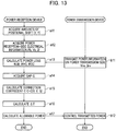
- the flow chart in Fig. 13 illustrates the processing by the temperature estimation unit 33 illustrated in Fig. 1 and the processing by the power transmission controller 15.
- the temperature estimation unit 33 acquires the data of the amounts of planar positional shift Lx, Ly of the power reception coil unit 22 from the power transmission coil unit 12, in Step all.
- the above-described methods illustrated in Fig. 7 and Fig. 8 can be employed.
- Step a12 the temperature estimation unit 33 acquires a received power Pb and received voltage Vb in the power reception coil unit 22, and an electric current I2 flowing through the power reception coil 41. These data can be acquired from the detection values of a voltmeter and ammeter (not illustrated) provided in the power reception coil unit 22.
- Step b11 the power transmission controller 15 measures an output voltage Vinv and output current Iinv of the inverter 113, and transmits these data to the temperature estimation unit 33 through the wireless communication unit 14 and the wireless communication unit 24.
- Step a13 the temperature estimation unit 33 calculates the respective power losses WJB, WVC, and WGC on the basis of various data.
- each power loss is a copper loss and is proportional to the square of the electric current, and therefore the calculation can be conducted on the basis of this relationship.
- Step a14 the gap G between the power transmission coil unit 12 and the power reception coil unit 22 is calculated.
- the gap G can be obtained by employing the above-described method illustrated in Fig. 9 and Fig. 10 .
- Step a15 the temperature estimation unit 33 obtains the correction coefficient C for correcting the power loss WGC. That is, because the amounts of positional shift Lx, Ly in the plane direction are acquired in the processing of Step a11 and the gap G is acquired in the processing of Step a14, the correction coefficient C can be obtained using the above-described approach on the basis of these numerical values.
- Step a16 the temperature estimation unit 33 calculates the increase in temperature ⁇ T of the power reception coil unit 22 by substituting the correction coefficient C acquired in the above-described processing into Formula (1) below.
- ⁇ T A * WJB + B * WVC + C * WGC
- Step a17 the temperature estimation unit 33 acquires the ambient temperature Ta of the vehicle 201, and adds the increase in temperature ⁇ T to this ambient temperature Ta. Then, the increase in temperature ⁇ T is controlled so as to satisfy Formula (5) below. Ta + ⁇ T + Tm ⁇ components allowable temperature where Tm is a margin.
- an allowable power Px which is an allowable value of the power generated in the power reception coil unit 22 is set so that the increase in temperature ⁇ T is reduced.
- the data of this allowable power Px is transmitted to the power supply device 100 via the wireless communication unit 24 and the wireless communication unit 14.
- Step b12 the power transmission controller 15 controls the power transmitted by the power transmission coil unit 12 so that the power generated in the power reception coil unit 22 becomes within the allowable power Px. In this manner, the control can be conducted so that the ambient temperature of the power reception coil unit 22 does not reach the components allowable temperature.
- the temperature estimation device changes, when the positional relationship between the power transmission coil 31 provided on the ground side and the power reception coil 41 provided in the vehicle 201 is positionally shifted from a normal positional relationship, the contribution to an increase in temperature due to the power loss WGC of the power transmission coil 31, in accordance with a magnitude of this positional shift amount. Accordingly, the ambient temperature of the power reception coil unit 22 can be accurately estimated without providing a temperature sensor for measuring the ambient temperature of the power reception coil 41.
- the transmitted power by the power supply device 100 can be controlled so that the ambient temperature of the power reception coil unit 22 does not rise to a component-restrictive temperature, and an excessive increase in temperature of the power reception coil unit 22 and electronic components therearound can be prevented.
- the charging time of the battery 28 increases.
- the information indicative of an increase in the charging time is displayed on the notification unit 37 to be notified to the occupant of the vehicle 201. In this manner, the occupant of the vehicle 201 can recognize in advance that the time needed for charging will increase and the occupant can have a sense of security.
- the temperature estimation unit 33 obtains the correction coefficient C on the basis of the amount of positional shift between the power transmission coil 31 and the power reception coil 41, and multiplies the power loss WGC of the power transmission coil 31 by the correction coefficient C, thereby changing the contribution to an increase in temperature due to the power loss WGC of this power transmission coil 31. Accordingly, the ambient temperature of the power reception coil unit 22 can be estimated more accurately.
- the amounts of planar positional shift X, Y which are the amounts of positional shift between the power transmission coil 31 and the power reception coil 41, and the gap G are acquired, and the correction coefficient C is obtained on the basis of these data. Furthermore, the power loss WGC is multiplied by this correction coefficient C, and furthermore the increase in temperature ⁇ T is obtained from Formula (1) described above. Accordingly, the ambient temperature of the power reception coil unit 22 can be estimated more accurately
- the coupling coefficient ⁇ between the power transmission coil 31 and the power reception coil 41 is acquired, and the gap G is acquired on the basis of this coupling coefficient ⁇ and the amounts of planar positional shift Lx, Ly so that it is possible to dispense with the gap sensor 61 for measuring the gap G and to reduce the device scale.
- the coefficients a, b, and c in the above-described Formula (2) are measured, and furthermore the amounts of positional shift Lx, Ly and the gap G are substituted into Formula (2) to obtain the correction coefficient C, so that the correction coefficient C can be accurately obtained and accordingly the increase in temperature ⁇ T can be accurately estimated.
- each unit can be replaced with any configuration having a similar function.
Landscapes
- Engineering & Computer Science (AREA)
- Power Engineering (AREA)
- Transportation (AREA)
- Mechanical Engineering (AREA)
- Computer Networks & Wireless Communication (AREA)
- General Physics & Mathematics (AREA)
- Physics & Mathematics (AREA)
- Life Sciences & Earth Sciences (AREA)
- Sustainable Development (AREA)
- Sustainable Energy (AREA)
- Charge And Discharge Circuits For Batteries Or The Like (AREA)
- Electric Propulsion And Braking For Vehicles (AREA)
- Current-Collector Devices For Electrically Propelled Vehicles (AREA)
Abstract
Description
- The present invention relates to a temperature estimation device and a temperature estimation method for a contactless power reception device which estimate the temperature of the power reception device that contactlessly receives the power transmitted from a power transmission coil.
- There has been proposed a contactless power supply system that contactlessly supplies power to charge a battery mounted on an electric vehicle. In the contactless power supply system, power is transmitted via a power transmission coil from a power transmission device provided on the ground side and the transmitted power is received by a power reception coil of a power reception device mounted on the vehicle. Then, the received power is supplied to loads, such as a battery and a motor.
- In such a contactless power supply system, when a change in the gap between the power transmission coil and the power reception coil or a planar positional shift between the power transmission coil and the power reception coil occurs, the power loss of the power transmission coil increases and the temperature of the power reception device rises due to an increase of this power loss. Therefore, the temperature of the power reception device needs to be monitored.
- Patent Literature 1 discloses a temperature control device that estimates the temperature of an electronic device by calculation. In this Patent Literature 1, the temperature is estimated by integrating the quantity of heat on the basis of operation mode information and an operation time. Then, when the estimated temperature reaches a threshold, the operation mode is switched to an operation mode which generates a less amount of heat. However, in Patent Literature 1, the temperature is estimated by detecting the operation mode inside the device, and the influence from an external device is not taken into consideration.
- Patent Literature 1: Japanese Patent Laid-Open Publication No.
7-334263 - As described above, in order to prevent an increase in temperature of a contactless power reception device, the temperature of this contactless power reception device needs to be monitored. However, if a temperature sensor is installed, there arise problems that the device increases in scale and the cost increases, and therefore there increases a demand for estimating the temperature without installing a device, such as a temperature sensor.
- The present invention has been made in order to solve the conventional problems, and has an object to provide a temperature estimation device and temperature estimation method for a contactless power reception device capable of accurately estimating the ambient temperature of a power reception coil.
- A temperature estimation device for a contactless power reception device according to an aspect of the present invention includes: a power transmission-side power loss acquisition unit which acquires the power loss of a power transmission coil; and a temperature estimation unit which estimates the ambient temperature of a power reception coil on the basis of a preset amount of heat generation of a power reception device and the power loss of the power transmission coil. When the positional relationship between the power transmission coil and the power reception coil is shifted from a normal positional relationship, the temperature estimation unit increases, in accordance with a magnitude of a positional shift amount, a contribution to a temperature rise due to the power loss of the power transmission coil.
- A temperature estimation method for a contactless power reception device according to an aspect of the present invention includes the steps of: acquiring a power loss of a power transmission coil; and estimating the ambient temperature of a power reception coil based on a preset amount of heat generation of a power reception device and the power loss of the power transmission coil. The temperature estimation method increases a contribution to a temperature rise due to the power loss of the power transmission coil, in accordance with a magnitude of a positional shift amount, when estimating the ambient temperature of the power reception coil, in a case where the positional relationship between the power transmission coil and the power reception coil is shifted from a normal positional relationship.
-
- [
Fig. 1] Fig. 1 is a block diagram illustrating a configuration of a contactless power supply system including a contactless power reception device to which a temperature estimation device according to an embodiment of the present invention is applied. - [
Fig. 2] Fig. 2 is an explanatory view illustrating a magnetic flux generated between a power transmission coil unit and a power reception coil unit according to an embodiment of the present invention. - [
Fig. 3] Fig. 3(a) is an explanatory view illustrating the magnetic flux when a gap between the power transmission coil unit and the power reception coil unit is Ga,Fig. 3(b) is an explanatory view illustrating the magnetic flux when the gap is Gb, andFig. 3(c) is a characteristic chart illustrating a relationship between the square of the gap and a correction coefficient C. - [
Fig. 4] Fig. 4(a) is an explanatory view illustrating the magnetic flux when there is no positional shift in the short side direction between the power transmission coil unit and the power reception coil unit,Fig. 4(b) is an explanatory view illustrating the positional relationship between the power transmission coil unit and the power reception coil unit in the case ofFig. 4(a), Fig. 4(c) is an explanatory view illustrating the magnetic flux when there is a positional shift in the short side direction between the power transmission coil unit and the power reception coil unit, andFig. 4(d) is an explanatory view illustrating the positional relationship between the power transmission coil unit and the power reception coil unit in the case ofFig. 4(c) . - [
Fig. 5] Fig. 5(a) is an explanatory view illustrating the magnetic flux when there is no positional shift in the long side direction between the power transmission coil unit and the power reception coil unit,Fig. 5(b) is an explanatory view illustrating the positional relationship between the power transmission coil unit and the power reception coil unit in the case ofFig. 5(a), Fig. 5(c) is an explanatory view illustrating the magnetic flux when there is a positional shift in the long side direction between the power transmission coil unit and the power reception coil unit, andFig. 5(d) is an explanatory view illustrating the positional relationship between the power transmission coil unit and the power reception coil unit in the case ofFig. 4(c) . - [
Fig. 6] Fig. 6 is a characteristic chart illustrating a relationship between the amounts of positional shift in the short side direction and long side direction and the correction coefficient C. - [
Fig. 7] Fig. 7 is an explanatory view illustrating how the amount of positional shift in the X-axis direction (short side direction) is measured using a forward-distance sensor. - [
Fig. 8] Fig. 8 is an explanatory view illustrating how the amounts of positional shift in the X-axis direction and Y-axis direction (long side direction) are measured from the bird's-eye view image of a vehicle. - [
Fig. 9] Fig. 9 is an explanatory view illustrating how the gap G is measured using a gap sensor. - [
Fig. 10] Fig. 10 is an equivalent circuit diagram of a power transmission coil unit and power reception coil unit. - [
Fig. 11] Fig. 11 is a graph illustrating a relationship between the amount of positional shift between the power transmission coil unit and the power reception coil unit and the correction coefficient C. - [
Fig. 12] Figs. 12(a) to 12(c) are explanatory views each illustrating the positional relationship between the power transmission coil and the power reception coil, and illustrate a case where a positional shift occurs on the plus side in the short side direction, a case where a positional shift occurs on the minus side in the short side direction, and a case where a positional shift occurs in the long side direction, respectively - [
Fig. 13] Fig. 13 is a flow chart illustrating a procedure of temperature estimation processing according to an embodiment of the present invention. - Hereinafter, an embodiment of the present invention will be described with reference to the drawings.
Fig. 1 is a block diagram illustrating a configuration of a contactless power supply system according to the embodiment of the present invention. As illustrated inFig. 1 , a contactlesspower supply system 101 according to the present embodiment includes: apower supply device 100 which is provided on the ground side and transmits power; and a power reception device 200 (contactless power reception device) which is mounted on avehicle 201, receives the power transmitted from thepower supply device 100, and charges abattery 28. - The
power supply device 100 is installed on a charging stand or the like provided with a parking space for thevehicle 201, and contactlessly transmits power to thevehicle 201. Thispower supply device 100 is mainly constituted by apower controller 11, a powertransmission coil unit 12, awireless communication unit 14, and apower transmission controller 15. Furthermore, thispower supply device 100 includes acamera 13 which images, from the above of the parking space, thevehicle 201 parked in this parking space. - The
power controller 11 has a function to convert an alternating current (AC) power output from an AC power supply 300 (e.g., 50 Hz, 200 V) to a high frequency AC power and transmit the power to the powertransmission coil unit 12. Thispower controller 11 includes arectifier 111, a PFC (Power Factor Correction)circuit 112, and aninverter 113. - The
rectifier 111 converts the AC power output from theAC power supply 300 to a direct current (DC) power. ThePFC circuit 112 includes, for example, a step-up chopper circuit etc. and is a circuit for improving the power factor by shaping the waveform of an output current from therectifier 111. The output of thePFC circuit 112 is smoothed by a smoothing capacitor. - The
inverter 113 includes a plurality of switching elements (e.g., insulating gate bipolar transistor (IGBT)), and converts a DC power to an AC power of a desired frequency by controlling the ON/OFF of each switching element. - The power
transmission coil unit 12 is provided at a position which faces, when thevehicle 201 stops at a desired position of the parking space, a powerreception coil unit 22 provided in thepower reception device 200. Then, the powertransmission coil unit 12 contactlessly transmits power to the powerreception coil unit 22. This powertransmission coil unit 12 includes apower transmission coil 31 and aferrite plate 35 formed of a material with high magnetic permeability and having a planar shape, as illustrated inFig. 2 . - The
wireless communication unit 14 performs two-way communication with awireless communication unit 24 provided in thepower reception device 200. By this communication, as described later, transmitted are various data, such as an output voltage Vinv and output current Iinv of theinverter 113 detected by thepower supply device 100, and a power loss WGC in the powertransmission coil unit 12, and a coupling coefficient κ described later, to thepower reception device 200. - The
power transmission controller 15 generally controls the wholepower supply device 100. Thispower transmission controller 15 can be configured using a microcomputer mainly including, for example, a central processing unit (CPU), a read-only memory (ROM), a random-access memory (RAM), and an input/output (I/O) interface. In particular, thispower transmission controller 15 controls thepower controller 11, thewireless communication unit 14, and thecamera 13. - On the other hand, the
power reception device 200 mounted on thevehicle 201 includes the powerreception coil unit 22, thewireless communication unit 24, acharging controller 25, arectifier 26, arelay 27, and atemperature estimation unit 33. Furthermore, thepower reception device 200 includes thebattery 28 which stores power and supplies a DC power to aninverter 29, and anotification unit 37 which notifies an occupant of thevehicle 201 of various information. Theinverter 29 converts a DC power to an AC power, and supplies the converted AC power to amotor 30. - Moreover, at a front end part of the
vehicle 201, there is provided a forward-distance sensor 51 for measuring the distance from this front end part to a wall surface 52 (seeFig. 7 ) provided in the parking space. Furthermore, at a bottom part of thevehicle 201, there is provided agap sensor 61 for measuring the distance from this bottom part to the powertransmission coil unit 12. As the forward-distance sensor 51 and thegap sensor 61, an ultrasonic sensor can be used, for example. - The power
reception coil unit 22 is a coil for contactlessly receiving the power transmitted from the powertransmission coil unit 12. This powerreception coil unit 22 includes thepower transmission coil 31 and theferrite plate 35 formed of a material with high magnetic permeability and having a planar shape, as illustrated inFig. 2 . - The
wireless communication unit 24 performs two-way communication with thewireless communication units 14 provided in thepower supply device 100. Therectifier 26 is connected to the powerreception coil unit 22, converts an AC power output from this powerreception coil unit 22 to a DC power and outputs the DC power. Thisrectifier 26 is mounted on acircuit board 44 inside anelectric box 45 provided in a vicinity of the bottom face of thevehicle 201, as illustrated inFig. 2 . - The
relay 27 includes a relay switch whose ON/OFF states are switched under the control of the chargingcontroller 25. Therelay 27 is capable of separating a circuit including thebattery 28 from a circuit including the powerreception coil unit 22 and therectifier 26 by turning off the relay switch. - On the basis of a power loss WJB of the
circuit board 44 mounted inside the electric box 45 (seeFig. 2 ) having therectifier 26 mounted therein, a power loss WVC in the powerreception coil unit 22, and a power loss WGC in the powertransmission coil unit 12, thetemperature estimation unit 33 estimates the ambient temperature (ambient temperature of the power reception coil) of the powerreception coil unit 22, such as aferrite plate 42, a copper wire of the coil, and other circuit elements, using an approach described later. The details will be described later. Here, the amount of heat generation caused by the power loss WJB of thecircuit board 44 and the power loss WVC in the powerreception coil unit 22 is the amount of heat generation of the power reception device. - The
notification unit 37 includes a display unit, such as a display, and notifies an occupant of thevehicle 201 of various information including the information about contactless power supply. In particular, as described later, when the ambient temperature of the powerreception coil unit 22 is estimated to exceed a threshold temperature by thetemperature estimation unit 33, this fact is displayed on the display. Moreover, when the ambient temperature is estimated to exceed a threshold temperature, and thereby the transmission power from thepower supply device 100 is reduced (the details will be described later) and the time needed to charge thebattery 28 is accordingly changed, this fact is displayed on the display to be notified to the occupant. - The charging
controller 25 generally controls thepower reception device 200. In particular, the chargingcontroller 25 acquires the information about the output voltage Vinv and output current Iinv of theinverter 113 which is transmitted from thepower supply device 100 via thewireless communication unit 24. Furthermore, the chargingcontroller 25 acquires the information about the power loss WGC in the powertransmission coil unit 12. That is, the chargingcontroller 25 has a function as a power transmission-side power loss acquisition unit which acquires the information about the power loss of the powertransmission coil unit 12. - Furthermore, the charging
controller 25 has a function, as a positional shift amount acquisition unit, which acquires the amounts of planar positional shift Lx, Ly of the powerreception coil unit 22 from the powertransmission coil unit 12, and the gap G, on the basis of a distance to thewall surface 52 detected by the forward-distance sensor 51 and a distance to the powertransmission coil unit 12 detected by thegap sensor 61. The chargingcontroller 25 and thetemperature estimation unit 33 can be configured using a microcomputer mainly including, for example, a central processing unit (CPU), a read-only memory (ROM), a random-access memory (RAM), and an input/output (I/O) interface. - Then, in the contactless
power supply system 101 illustrated inFig. 1 , power is transmitted in a contactless state by electromagnetic induction between the powertransmission coil unit 12 and the powerreception coil unit 22. That is, if an electric current flows through the powertransmission coil unit 12, magnetic coupling occurs between the powertransmission coil unit 12 and the powerreception coil unit 22, so that power can be contactlessly transmitted to the powerreception coil unit 22 from the powertransmission coil unit 12. - Furthermore, in the present embodiment, when the ambient temperature of the power
reception coil unit 22 reaches a preset threshold temperature during transmission of power, the transmitted power is reduced to prevent the ambient temperature of the powerreception coil unit 22 from abnormally rising. - Next, a factor causing an increase in temperature of the power
reception coil unit 22 during transmission of power will be explained with reference toFig. 2. Fig. 2 is an explanatory view illustrating a magnetic flux generated between the powertransmission coil unit 12 and the powerreception coil unit 22. - The factor causing an increase in ambient temperature of the power
reception coil unit 22 illustrated inFig. 2 includes the power loss WJB inside theelectric box 45. As illustrated inFig. 2 , thecircuit board 44 is arranged inside theelectric box 45, and various electronic components including therectifier 26 are mounted on thiscircuit board 44. Accordingly, thiscircuit board 44 generates heat due to the power loss WJB generated during operation, causing an increase in ambient temperature of the powerreception coil unit 22. - Furthermore, the factor causing an increase in ambient temperature of the power
reception coil unit 22 may include the power loss WVC of the powerreception coil unit 22 and the power loss WGC of the powertransmission coil unit 12. Accordingly, if an increase in temperature of the powerreception coil unit 22 is designated by ΔT, this increase in temperature ΔT can be expressed by Formula (1) below using correction coefficients A, B, and C.
- Note that ΔT is an increase in temperature after a sufficient time has elapsed.
- Then, the increase in temperature ΔT can be calculated from Formula (1), and furthermore the ambient temperature of the power
reception coil unit 22 can be estimated on the basis of the ambient temperature detected by an ambient temperature sensor (not illustrated) provided in place in thepower supply device 100 or thevehicle 201. Specifically, the ambient temperature of the powerreception coil unit 22 can be obtained by adding the increase in temperature ΔT to the ambient temperature. - Moreover, in Formula (1), because each of the power losses WJB, WVC, and WGC is a copper loss and proportional to the square of an electric current, the ambient temperature of the power
reception coil unit 22 can be calculated on the basis of an electric current flowing through thecircuit board 44 inside theelectric box 45, an electric current flowing through a circuit including acircuit board 43 of the powerreception coil unit 22, and an electric current flowing through the powertransmission coil unit 12. Furthermore, because the correction coefficients A and B are the numerical values specific to thepower reception device 200, they are already known. Accordingly, if the correction coefficient C of the power loss WGC in the powertransmission coil unit 12 can be obtained, the increase in temperature ΔT can be calculated from the above-described Formula (1). The correction coefficient C is a numerical value varying with the relative positional relationship between the powertransmission coil unit 12 and the powerreception coil unit 22, and the calculation method thereof will be described later. - Next, the principle that the power
reception coil unit 22 generates heat in contactlessly transmitting power to the powerreception coil unit 22 from the powertransmission coil unit 12, and the relationship with the correction coefficient C will be explained. As illustrated inFig. 2 , the powertransmission coil unit 12 is constituted by theferrite plate 35 and thepower transmission coil 31 wound around the upper face of thisferrite plate 35. Moreover, the powerreception coil unit 22 includes theferrite plate 42 and apower reception coil 41 wound around the lower face of thisferrite plate 42, and furthermore thecircuit board 43 having various electronic components mounted thereon is provided on the upper face of theferrite plate 42. - Then, when the
vehicle 201 stops at a desired position in a parking space, the powerreception coil unit 22 is installed at a position facing the powertransmission coil unit 12. Accordingly, if in this state an electric current is supplied to thepower transmission coil 31 for excitation, a magnetic flux is formed as indicated by an arrow Y1. Because this magnetic flux passes through theferrite plate 42 of the powerreception coil unit 22 and interlinks with thepower reception coil 41, power will be transmitted to thispower reception coil 41. - Moreover, the magnetic flux passing through the
ferrite plate 42 varies with a relative positional relationship between the powertransmission coil unit 12 and the powerreception coil unit 22. That is, when thevehicle 201 is not stopped at a desired position inside the parking space, a planar positional shift occurs between the powertransmission coil unit 12 and the powerreception coil unit 22. Furthermore, the distance (gap G) between the powertransmission coil unit 12 and the powerreception coil unit 22 varies with the number of occupants riding on thevehicle 201 and the like. When such a positional shift occurs, the magnetic flux passing through theferrite plate 42 varies to generate a high-density magnetic-flux part, and therefore magnetic saturation occurs to cause heat generation. That is, the amount of heat generation will vary with the relative positional relationship between the powertransmission coil unit 12 and the powerreception coil unit 22. - Hereinafter, how the magnetic flux passing through the
ferrite plate 42 of the powerreception coil unit 22 varies with the gap G between the powertransmission coil unit 12 and the powerreception coil unit 22 will be explained with reference toFig. 3 . -
Fig. 3(a) illustrates the magnetic flux when the gap G which is the distance between the powertransmission coil unit 12 and the powerreception coil unit 22 is a reference value Ga, whileFig. 3(b) illustrates the magnetic flux when the gap G becomes Gb which is longer than the reference value Ga. As seen fromFigs. 3(a) and 3(b) , when the gap G becomes longer, the magnetic flux which reaches the powerreception coil unit 22 from the powertransmission coil unit 12 decreases. That is, the magnetic flux indicated by an arrow Y12 decreases relative to the magnetic flux indicated by an arrow Y11. More specifically, the magnetic flux passing through areas R21 and R22 illustrated inFig. 3(b) decreases relative to the magnetic flux passing through areas R11 and R12 illustrated inFig. 3(a) . - As the result, the magnetic flux passing through the
ferrite plate 42 of the powerreception coil unit 22 decreases, and the amount of heat generation of thisferrite plate 42 decreases. In this case, because the magnetic flux passing through theferrite plate 42 decreases in inverse proportion to the square of the gap G, the amount of heat generation will decrease in inverse proportion to the square of the gap G. Accordingly, as illustrated inFig. 3(c) , the above-described correction coefficient C may be set so as to have a characteristic inversely proportional to the square of the gap G. - Next, a change in the amount of heat generation corresponding to the amount of planar positional shift of the power
reception coil unit 22 from the powertransmission coil unit 12 will be explained with reference to the explanatory views illustrated inFig. 4 to Fig. 6 .Fig. 4(a) is a cross sectional view in the X-axis direction when the powerreception coil unit 22 is not positionally shifted from the powertransmission coil unit 12, in which an arrow Y13 indicates the magnetic flux. Moreover,Fig. 4(b) schematically illustrates the plan view in this case. Note that, as illustrated inFig. 4(b) , thepower reception coil 41 has a rectangular shape, in which the short side direction is set to the X-axis direction. - On the other hand,
Fig. 4(c) is a cross sectional view in the X-axis direction when the powerreception coil unit 22 is positionally shifted by a distance L1 in the X-axis direction, in which an arrow Y14 indicates the magnetic flux. Moreover,Fig. 4(d) schematically illustrates a plan view in this case. - As seen from comparison between
Fig. 4(a) and Fig. 4(c) , a positional shift in the X-axis direction occurring between the powertransmission coil unit 12 and the powerreception coil unit 22 reduces a coupling coefficient (designated by "κ" ) between the both coils. Accordingly, thepower transmission controller 15 of thepower supply device 100 increases the power supplied to the powertransmission coil unit 12 so that a desired power is generated in the powerreception coil unit 22. As the result, the magnetic flux output from thepower transmission coil 31 increases as illustrated inFig. 4(c) , and the magnetic flux passing through theferrite plate 42 also increases accordingly. Therefore, the concentration of the magnetic flux occurs in theferrite plate 42, causing an increase of the ambient temperature of the powerreception coil unit 22. Moreover, the ambient temperature of the powerreception coil unit 22 will increase linearly with respect to the amount of positional shift in the X-axis direction. - Next, a positional shift in the Y-axis direction (direction perpendicular to the X-axis) will be explained.
Fig. 5(a) is a cross sectional view in the Y-axis direction when the powerreception coil unit 22 is not positionally shifted from the powertransmission coil unit 12, in which an arrow Y15 indicates a magnetic flux. Moreover,Fig. 5(b) schematically illustrates the plan view in this case. Note that, as illustrated inFig. 5(b) , thepower reception coil 41 has a rectangular shape, in which the long side direction is set to the Y-axis direction. - On the other hand,
Fig. 5(c) is a cross sectional view in the Y-axis direction when the powerreception coil unit 22 is positionally shifted by the distance L1 in the Y-axis direction, in which an arrow Y16 indicates a magnetic flux. Moreover,Fig. 5(d) schematically illustrates a plan view in this case. - As seen from the comparison between
Fig. 5(a) and Fig. 5(c) , a positional shift in the Y-axis direction occurring between the powertransmission coil unit 12 and the powerreception coil unit 22 reduces the coupling coefficient κ between the both coils. Accordingly, thepower transmission controller 15 of thepower supply device 100 increases the power supplied to the powertransmission coil unit 12 so that a desired power is generated in the powerreception coil unit 22. As the result, the magnetic flux output from thepower transmission coil 31 increases as illustrated inFig. 5(c) , and the magnetic flux passing through theferrite plate 42 also increases accordingly Therefore, the concentration of the magnetic flux occurs in theferrite plate 42, causing an increase of the ambient temperature of the powerreception coil unit 22. Moreover, the ambient temperature of the powerreception coil unit 22 will increase linearly with respect to the amount of positional shift in the Y-axis direction. - Moreover, the positional shift in the Y-axis direction affects the increase in temperature more than the above-described positional shift in the X-axis direction. That is, when the amounts of positional shift in the both directions are the same, the positional shift in the Y-axis direction (long side direction) generates more heat than the positional shift in the X-axis direction (short side direction). Accordingly, as illustrated in
Fig. 6 , the correction coefficient C may be set so as to linearly vary with respect to the amount of positional shift in the X-axis direction (see a straight line Q3), and the correction coefficient C may be set so as to linearly vary with respect to the amount of positional shift in the Y-axis direction (long side direction) (see a straight line Q2). In this case, the correction coefficient C is set so that the straight line Q2 has a lager gradient than the straight line Q3. - Furthermore, in summary, it turns out that there are relationships (A) and (B) below between the correction coefficient C and the positional relationship between the coils.
- (A) The correction coefficient C is inversely proportional to the square of the gap G between the power
transmission coil unit 12 and the powerreception coil unit 22. - (B) The correction coefficient C varies linearly with respect to the amount of positional shift (this is designated by "Lx") in the X-axis direction and to the amount of positional shift (this is designated by "Ly") in the Y-axis direction.
- Accordingly, if the correction coefficient C is determined on the basis of the relationships (A) and (B), the amount of heat generation due to the power loss WGC of the power transmission side coil can be corrected. Specifically, the correction coefficient C can be obtained from Formula (2) below using coefficients a, b, and c.

- Then, the
temperature estimation unit 33 illustrated inFig. 1 obtains the amounts of positional shift Lx, Ly and the gap G, to thereby calculate the correction coefficient C, substitutes this correction coefficient C into the above-described Formula (1), and multiplies this correction coefficient C by the power loss WGC of thepower transmission coil 31, thereby obtaining the increase in temperature ΔT. That is, the contribution to an increase in temperature due to thepower transmission coil 31 is changed using the correction coefficient C which varies with a magnitude of the positional shift amount. Then, the ambient temperature of the powerreception coil unit 22 is estimated by adding the increase in temperature ΔT to the ambient temperature of the powerreception coil unit 22, and the control is conducted, when this estimated temperature reaches a preset threshold temperature, so as to suppress the transmitted power and suppress a further increase in temperature. - Next, a method for detecting the amounts of planar positional shift Lx, Ly will be explained with reference to
Fig. 7 and Fig. 8. Fig. 7 is an explanatory view illustrating a first method for detecting the amount of positional shift Lx in the X-axis direction. As illustrated inFig. 7 , the forward-distance sensor 51 provided at a front end part of thevehicle 201 transmits an ultrasonic signal to measure the distance L to thewall surface 52 provided in place in the parking space. Then, on the basis of a distance Lg (known numerical value) from a center point C2 of the powertransmission coil unit 12 to thewall surface 52, a distance Lv (known numerical value) from a center point C1 of the powerreception coil unit 22 to the front end part, and the distance L (measured value), the distance between the respective center points C1 and C2, that is, the amount of positional shift Lx in the X-axis direction is calculated by Formula (3) below.
- In this manner, the amount of positional shift Lx in the X-axis direction can be obtained.
-
Fig. 8 is an explanatory view illustrating a second method for detecting the amount of positional shift Lx in the X-axis direction and the amount of positional shift Ly in the Y-axis direction. Thevehicle 201 stopping inside aparking frame 54 of the parking space is photographed from the above using thecamera 13 provided in thepower supply device 100. As the result, a bird's-eye view image like the one illustrated inFig. 8 can be obtained. Then, the amount of planar positional shift between the center point C2 of the powertransmission coil unit 12 and the center point C1 of the powerreception coil unit 22 is measured on the basis of the positional relationship between thevehicle 201 and theparking frame 54. Specifically, as illustrated inFig. 8 , the amount of positional shift Lx in the X-axis direction and the amount of positional shift Ly in the Y-axis direction can be acquired. - Next, a method for detecting the gap G between the power
transmission coil unit 12 and the powerreception coil unit 22 will be explained with reference toFig. 9 and Fig. 10 . As illustrated inFig. 9 , thegap sensor 61 installed on a bottom part of thevehicle 201 can measure the gap G by transmitting an ultrasonic signal and receiving a reflected signal thereof. - Moreover, as another method, the gap G can be obtained on the basis of the coupling coefficient κ between the
power transmission coil 31 and thepower reception coil 41 and the respective amounts of positional shift Lx, Ly. Hereinafter, this will be explained with reference toFig. 10 andFig. 11 .Fig. 10 is an equivalent circuit diagram of the powertransmission coil unit 12 and powerreception coil unit 22, in which a load RL corresponds to thebattery 28 illustrated inFig. 1 . As described in Japanese Patent Laid-Open Publication No.2013-81275 power transmission coil 31, an electric current I flowing through thepower transmission coil 31, and the coupling coefficient κ between thepower transmission coil 31 and thepower reception coil 41.
[Math. 1]
- Accordingly, the coupling coefficient κ can be obtained by measuring the voltage V generated in the
power transmission coil 31 and the electric current I flowing through thepower transmission coil 31. This coupling coefficient κ can be acquired by the chargingcontroller 25 through the communication between thewireless communication unit 14 and thewireless communication unit 24. That is, the chargingcontroller 25 has a function as a coupling coefficient acquisition unit which acquires the coupling coefficient κ between thepower transmission coil 31 and thepower reception coil 41. - Furthermore, once the amounts of positional shift Lx, Ly in the X-axis and Y-axis directions and the coupling coefficient κ are determined, the gap G can be obtained. In the present embodiment, the gap G can be obtained by setting, in advance, a map indicating a relationship among Lx, Ly, κ and the gap G in a storage area (not illustrated) of the
temperature estimation unit 33, and then applying the amounts of positional shift Lx, Ly, and κ obtained in the above-described procedure to this map. - Because the amounts of positional shift Lx, Ly, and the gap G can be obtained using the above-described method, the correction coefficient C can be obtained from the above-described Formula (2). In the present embodiment, the correction coefficient C is calculated by preparing, in advance, a correspondence map indicating a relationship among the amounts of positional shift Lx, Ly, the gap G, and the correction coefficient C, and substituting each numerical value into this correspondence map.
- Hereinafter, the relationship among the amounts of positional shift Lx, Ly, the gap G, and the correction coefficient C will be explained with reference to a graph illustrated in
Fig. 11 and an explanatory view illustrated inFig. 12 . -
Fig. 11 is a graph illustrating a change in the correction coefficient C obtained in performing an experiment for actually changing the amounts of positional shift Lx, Ly and the gap G. Reference sign q1 indicates the correction coefficient C when Lx=100 mm, Ly=0 mm, and G=100 mm.Fig. 12 is an explanatory view illustrating the relative positional relationship between thepower transmission coil 31 and thepower reception coil 41, in which the reference sign q1 inFig. 11 indicates a state where the center C1 of thepower reception coil 41 is shifted, by 100 mm in the plus direction of the X-axis, from the center C2 of thepower transmission coil 31, as illustrated inFig. 12(a) . As indicated by the reference sign q1 ofFig. 11 , the correction coefficient C is 0.10 in this case. - Similarly, reference sign q2 in
Fig. 11 indicates the correction coefficient C when Lx=-100 mm, Ly=0 mm, and G=100 mm, and indicates a state where the center C1 of thepower reception coil 41 is shifted, by 100 mm in the minus direction of the X-axis, from the center C2 of thepower transmission coil 31, as illustrated inFig. 12(b) . As indicated by the reference sign q2 ofFig. 11 , the correction coefficient C is 0.15 in this case. - Reference sign q3 in
Fig. 11 indicates the correction coefficient C when Lx=0 mm, Ly=100 mm and G=100 mm, and indicates a state where the center C1 of thepower reception coil 41 is shifted, by 100 mm in the Y-axis direction, from the center C2 of thepower transmission coil 31, as illustrated inFig. 12(c) . As indicated by the reference sign q3 ofFig. 11 , the correction coefficient C is 0.25 in this case. - Furthermore, reference sign q4 in
Fig. 11 indicates the correction coefficient C when Lx=0 mm, Ly=0 mm and G=150 mm, reference sign q5 indicates the correction coefficient C when Lx=100 mm, Ly=0 mm, and G=150 mm, reference sign q6 indicates the correction coefficient C when Lx=-100 mm, Ly=0 mm, and G=150 mm, and reference sign q7 indicates the correction coefficient C when Lx=0 mm, Ly=100 mm, and G=150 mm. - As described above, the correction coefficient C can be obtained by applying the amounts of positional shift Lx, Ly and the gap G to a preset correspondence map.
- Furthermore, each of the coefficients a, b, and c of Formula (2) below may be obtained on the basis of the actual measurement value of the correction coefficient C. Then, the correction coefficient C may be calculated using these coefficients a, b, and c.

- Adoption of such a calculation method enables to calculate the correction coefficient C by an extremely simple method for substituting the Lx, Ly, and G into the calculation formula.
- Next, the processing operation of the temperature estimation device according to the present embodiment will be explained with reference to a flow chart illustrated in
Fig. 13 . The flow chart inFig. 13 illustrates the processing by thetemperature estimation unit 33 illustrated inFig. 1 and the processing by thepower transmission controller 15. - First, the
temperature estimation unit 33 acquires the data of the amounts of planar positional shift Lx, Ly of the powerreception coil unit 22 from the powertransmission coil unit 12, in Step all. For this processing, the above-described methods illustrated inFig. 7 and Fig. 8 can be employed. - In Step a12, the
temperature estimation unit 33 acquires a received power Pb and received voltage Vb in the powerreception coil unit 22, and an electric current I2 flowing through thepower reception coil 41. These data can be acquired from the detection values of a voltmeter and ammeter (not illustrated) provided in the powerreception coil unit 22. - In Step b11, the
power transmission controller 15 measures an output voltage Vinv and output current Iinv of theinverter 113, and transmits these data to thetemperature estimation unit 33 through thewireless communication unit 14 and thewireless communication unit 24. - In Step a13, the
temperature estimation unit 33 calculates the respective power losses WJB, WVC, and WGC on the basis of various data. As previously described, each power loss is a copper loss and is proportional to the square of the electric current, and therefore the calculation can be conducted on the basis of this relationship. - In Step a14, the gap G between the power
transmission coil unit 12 and the powerreception coil unit 22 is calculated. In this processing, the gap G can be obtained by employing the above-described method illustrated inFig. 9 and Fig. 10 . - In Step a15, the
temperature estimation unit 33 obtains the correction coefficient C for correcting the power loss WGC. That is, because the amounts of positional shift Lx, Ly in the plane direction are acquired in the processing of Step a11 and the gap G is acquired in the processing of Step a14, the correction coefficient C can be obtained using the above-described approach on the basis of these numerical values. - In Step a16, the
temperature estimation unit 33 calculates the increase in temperature ΔT of the powerreception coil unit 22 by substituting the correction coefficient C acquired in the above-described processing into Formula (1) below.
- In Step a17, the
temperature estimation unit 33 acquires the ambient temperature Ta of thevehicle 201, and adds the increase in temperature ΔT to this ambient temperature Ta. Then, the increase in temperature ΔT is controlled so as to satisfy Formula (5) below.
- That is, when "Ta+ΔT+Tm" reaches a "components allowable temperature", an allowable power Px which is an allowable value of the power generated in the power
reception coil unit 22 is set so that the increase in temperature ΔT is reduced. The data of this allowable power Px is transmitted to thepower supply device 100 via thewireless communication unit 24 and thewireless communication unit 14. - Subsequently, in Step b12, the
power transmission controller 15 controls the power transmitted by the powertransmission coil unit 12 so that the power generated in the powerreception coil unit 22 becomes within the allowable power Px. In this manner, the control can be conducted so that the ambient temperature of the powerreception coil unit 22 does not reach the components allowable temperature. - In this manner, the temperature estimation device according to the present embodiment changes, when the positional relationship between the
power transmission coil 31 provided on the ground side and thepower reception coil 41 provided in thevehicle 201 is positionally shifted from a normal positional relationship, the contribution to an increase in temperature due to the power loss WGC of thepower transmission coil 31, in accordance with a magnitude of this positional shift amount. Accordingly, the ambient temperature of the powerreception coil unit 22 can be accurately estimated without providing a temperature sensor for measuring the ambient temperature of thepower reception coil 41. - Moreover, the transmitted power by the
power supply device 100 can be controlled so that the ambient temperature of the powerreception coil unit 22 does not rise to a component-restrictive temperature, and an excessive increase in temperature of the powerreception coil unit 22 and electronic components therearound can be prevented. - Furthermore, if the control is conducted so that the transmitted power from the power
transmission coil unit 12 decreases, the charging time of thebattery 28 increases. In the present embodiment, when control is conducted by thetemperature estimation unit 33 so as to reduce the transmitted power, the information indicative of an increase in the charging time is displayed on thenotification unit 37 to be notified to the occupant of thevehicle 201. In this manner, the occupant of thevehicle 201 can recognize in advance that the time needed for charging will increase and the occupant can have a sense of security. - Moreover, the
temperature estimation unit 33 obtains the correction coefficient C on the basis of the amount of positional shift between thepower transmission coil 31 and thepower reception coil 41, and multiplies the power loss WGC of thepower transmission coil 31 by the correction coefficient C, thereby changing the contribution to an increase in temperature due to the power loss WGC of thispower transmission coil 31. Accordingly, the ambient temperature of the powerreception coil unit 22 can be estimated more accurately. - Furthermore, the amounts of planar positional shift X, Y which are the amounts of positional shift between the
power transmission coil 31 and thepower reception coil 41, and the gap G are acquired, and the correction coefficient C is obtained on the basis of these data. Furthermore, the power loss WGC is multiplied by this correction coefficient C, and furthermore the increase in temperature ΔT is obtained from Formula (1) described above. Accordingly, the ambient temperature of the powerreception coil unit 22 can be estimated more accurately - Moreover, the coupling coefficient κ between the
power transmission coil 31 and thepower reception coil 41 is acquired, and the gap G is acquired on the basis of this coupling coefficient κ and the amounts of planar positional shift Lx, Ly so that it is possible to dispense with thegap sensor 61 for measuring the gap G and to reduce the device scale. - Furthermore, the coefficients a, b, and c in the above-described Formula (2) are measured, and furthermore the amounts of positional shift Lx, Ly and the gap G are substituted into Formula (2) to obtain the correction coefficient C, so that the correction coefficient C can be accurately obtained and accordingly the increase in temperature ΔT can be accurately estimated.
- In the foregoing, the temperature estimation device and temperature estimation method for the contactless power reception device of the present invention have been explained on the basis of the illustrated embodiment, but the present invention is not limited thereto. The configuration of each unit can be replaced with any configuration having a similar function.
-
- 11
- power controller
- 12
- power transmission coil unit
- 13
- camera
- 14
- wireless communication unit
- 15
- power transmission controller
- 22
- power reception coil unit
- 24
- wireless communication unit
- 25
- charging controller
- 26
- rectifier
- 27
- relay
- 28
- battery
- 29
- inverter
- 30
- motor
- 31
- power transmission coil
- 33
- temperature estimation unit
- 35
- ferrite plate
- 37
- notification unit
- 41
- power reception coil
- 42
- ferrite plate
- 43
- circuit board
- 44
- circuit board
- 45
- electric box
- 51
- forward-distance sensor
- 52
- wall surface
- 54
- parking frame
- 61
- gap sensor
- 100
- power supply device
- 101
- contactless power supply system
- 111
- rectifier
- 112
- PFC circuit
- 113
- inverter
- 200
- power reception device
- 201
- vehicle
- 300
- AC power supply
Claims (6)
- A temperature estimation device for a contactless power reception device, the temperature estimation device estimating an ambient temperature of a power reception coil of the power reception device that contactless receives a power transmitted from a power transmission coil via the power reception coil, the temperature estimation device comprising:a power transmission-side power loss acquisition unit which acquires a power loss of the power transmission coil; anda temperature estimation unit which estimates the ambient temperature of the power reception coil on a basis of a preset amount of heat generation of the power reception device and the power loss of the power transmission coil, whereinwhen a positional relationship between the power transmission coil and the power reception coil is shifted from a normal positional relationship, the temperature estimation unit changes, in accordance with a magnitude of a positional shift amount, a contribution to a temperature rise due to the power loss of the power transmission coil.
- The temperature estimation device for the contactless power reception device according to claim 1, further comprising:a positional shift amount acquisition unit which acquires a positional shift amount between the power transmission coil and the power reception coil, whereinthe temperature estimation unit changes a contribution to a temperature rise due to a power loss by multiplying the power loss of the power transmission coil by a correction coefficient which is determined in accordance with the magnitude of the positional shift amount.
- The temperature estimation device for the contactless power reception device according to claim 2, whereinthe positional shift amount acquisition unit acquires a gap between the power transmission coil and the power reception coil and a planar positional shift amount between the power transmission coil and the power reception coil, and determines the correction coefficient on a basis of the gap and the planar positional shift amount.
- The temperature estimation device for the contactless power reception device according to claim 3, further comprising:a coupling coefficient acquisition unit which acquires a coupling coefficient between the power transmission coil and the power reception coil, whereinthe positional shift amount acquisition unit acquires the gap on a basis of the planar positional shift amount and the coupling coefficient.
- The temperature estimation device for the contactless power reception device according to claim 2 or 3, whereinthe positional shift amount acquisition unit acquires a positional shift amount in an X-axis direction and a positional shift amount in a Y-axis direction perpendicular to the X-axis, as the planar positional shift amount, and further calculates the correction coefficient by a formula: C=(a*Lx+b*Ly+c)/G2
where a, b, and c are coefficients, G is the gap between the power transmission coil and the power reception coil, and Lx, Ly are the positional shift amounts in the X-axis direction and the Y-axis direction. - A temperature estimation method for a contactless power reception device, the temperature estimation method estimating an ambient temperature of a power reception coil of the power reception device that contactless receives a power transmitted from a power transmission coil via the power reception coil, the temperature estimation method comprising the steps of:acquiring a power loss of the power transmission coil;estimating the ambient temperature of the power reception coil on a basis of a preset amount of heat generation of the power reception device and the power loss of the power transmission coil; andchanging a contribution to a temperature rise due to the power loss of the power transmission coil, in accordance with a magnitude of a positional shift amount, when estimating the ambient temperature of the power reception coil, in a case where a positional relationship between the power transmission coil and the power reception coil is shifted from a normal positional relationship.
Applications Claiming Priority (1)
| Application Number | Priority Date | Filing Date | Title |
|---|---|---|---|
| PCT/JP2015/060814 WO2016162940A1 (en) | 2015-04-07 | 2015-04-07 | Temperature estimation device and temperature estimation method for contactless power-reception device |
Publications (3)
| Publication Number | Publication Date |
|---|---|
| EP3282554A1 true EP3282554A1 (en) | 2018-02-14 |
| EP3282554A4 EP3282554A4 (en) | 2018-03-21 |
| EP3282554B1 EP3282554B1 (en) | 2019-01-09 |
Family
ID=57072524
Family Applications (1)
| Application Number | Title | Priority Date | Filing Date |
|---|---|---|---|
| EP15888434.6A Active EP3282554B1 (en) | 2015-04-07 | 2015-04-07 | Temperature estimation device and temperature estimation method for contactless power-reception device |
Country Status (9)
| Country | Link |
|---|---|
| US (1) | US10180361B2 (en) |
| EP (1) | EP3282554B1 (en) |
| JP (1) | JP6424952B2 (en) |
| KR (1) | KR101821104B1 (en) |
| CN (1) | CN107580742B (en) |
| CA (1) | CA2981692C (en) |
| MX (1) | MX360378B (en) |
| RU (1) | RU2657705C1 (en) |
| WO (1) | WO2016162940A1 (en) |
Families Citing this family (11)
| Publication number | Priority date | Publication date | Assignee | Title |
|---|---|---|---|---|
| DE102015217274A1 (en) * | 2015-09-10 | 2017-03-16 | Robert Bosch Gmbh | Method for inductive energy transmission and apparatus for operating an inductive energy transmission device |
| JP6939098B2 (en) * | 2017-06-02 | 2021-09-22 | 日産自動車株式会社 | Foreign matter detection method by non-contact power supply system and non-contact power supply system |
| JP7027127B2 (en) * | 2017-11-06 | 2022-03-01 | キヤノン株式会社 | Portable devices, control methods and programs |
| JP7003221B2 (en) * | 2018-03-22 | 2022-01-20 | マクセル株式会社 | Contactless power transmission and reception system |
| JP6962302B2 (en) * | 2018-09-28 | 2021-11-05 | オムロン株式会社 | Power supply and power system |
| EP3863150A4 (en) * | 2018-10-05 | 2022-06-15 | IHI Corporation | Misalignment detection device and coil device |
| TWI745800B (en) * | 2018-12-21 | 2021-11-11 | 美商米沃奇電子工具公司 | Battery pack chargers, methods of controlling an operation of a battery pack charger, and charging circuits for a battery pack charger |
| CN109921494B (en) * | 2019-04-04 | 2021-04-27 | 北京品驰医疗设备有限公司 | Implanted medical device and charging control method thereof |
| KR20210129855A (en) * | 2020-04-21 | 2021-10-29 | 현대자동차주식회사 | Wireless power transfer machine, system and controlling method for vehicle |
| US12042043B2 (en) | 2020-06-11 | 2024-07-23 | Kohler Co. | Temperature tracking mirror |
| CN115575884B (en) * | 2022-11-08 | 2023-03-10 | 国网湖北省电力有限公司营销服务中心(计量中心) | Method for aligning charging quantity of charging piles in charging station and calculating metering error |
Family Cites Families (24)
| Publication number | Priority date | Publication date | Assignee | Title |
|---|---|---|---|---|
| EP0636869B1 (en) * | 1993-07-27 | 1999-01-13 | Siemens Aktiengesellschaft | Circuit arrangement for determining the temperature of a current regulated electric coil |
| JPH07334263A (en) | 1994-06-06 | 1995-12-22 | Fujitsu Ltd | Temperature controller |
| JP3644354B2 (en) * | 2000-05-09 | 2005-04-27 | トヨタ自動車株式会社 | Temperature estimation method and apparatus |
| US7071649B2 (en) * | 2001-08-17 | 2006-07-04 | Delphi Technologies, Inc. | Active temperature estimation for electric machines |
| JP4501433B2 (en) * | 2003-10-24 | 2010-07-14 | ダイキン工業株式会社 | DC motor coil temperature estimation method and apparatus |
| EP1799013B1 (en) * | 2005-12-14 | 2010-02-17 | Harman/Becker Automotive Systems GmbH | Method and system for predicting the behavior of a transducer |
| JP2010022183A (en) | 2008-02-08 | 2010-01-28 | Suri-Ai:Kk | Electric vehicle and inductive power-transmission device suitable therefor |
| JP5658592B2 (en) * | 2011-02-21 | 2015-01-28 | 国立大学法人埼玉大学 | Non-contact power feeding device for moving objects |
| JP2012244763A (en) * | 2011-05-19 | 2012-12-10 | Sony Corp | Power supply device, power supply system and electronic device |
| DE102011107375B4 (en) * | 2011-07-14 | 2013-02-21 | Maschinenfabrik Reinhausen Gmbh | Device for simulating and displaying the winding temperature of an electrical power transformer and suitable limiting circuit |
| JP5664544B2 (en) * | 2011-12-27 | 2015-02-04 | トヨタ自動車株式会社 | Non-contact power receiving device and non-contact charging system |
| US9417199B2 (en) * | 2012-01-17 | 2016-08-16 | Triune Systems, LLC | Method and system of wireless power transfer foreign object detection |
| JP5505444B2 (en) * | 2012-03-15 | 2014-05-28 | 株式会社デンソー | Foreign object detection device and non-contact power transfer system |
| RU124852U1 (en) * | 2012-07-19 | 2013-02-10 | Александр Викторович Атаманов | WIRELESS CHARGING SYSTEM FOR LOW-POWER ELECTRIC POWER CONSUMERS |
| US9963040B2 (en) * | 2012-09-13 | 2018-05-08 | Toyota Jidosha Kabushiki Kaisha | Non-contact power supply system, and power transmission device and vehicle used therein |
| JP6002513B2 (en) * | 2012-09-14 | 2016-10-05 | ソニー株式会社 | Non-contact power supply system, terminal device, and non-contact power supply method |
| US9356461B2 (en) * | 2012-09-25 | 2016-05-31 | Google Technology Holdings, LLC | Methods and systems for rapid wireless charging where the low state of charge (SOC) temperature dependent charging current and low SOC temperature limit are higher than the high SOC temperature dependent charging current and high SOC temperature limit |
| JP5607698B2 (en) * | 2012-10-18 | 2014-10-15 | ファナック株式会社 | Temperature estimation device for estimating the temperature of an electric motor |
| US9768643B2 (en) * | 2012-11-02 | 2017-09-19 | Panasonic Intellectual Property Management Co., Ltd. | Wireless power transmission system capable of continuing power transmission while suppressing heatup of foreign objects |
| FR3002036A1 (en) * | 2013-02-14 | 2014-08-15 | Hispano Suiza Sa | MEASURING THE HOMOGENEOUS TEMPERATURE OF A WINDING BY INCREASING THE RESISTANCE OF A WIRE |
| WO2014176784A1 (en) * | 2013-05-03 | 2014-11-06 | 3M Innovative Properties Company | System for monitoring temperature of electrical conductor |
| US9341520B2 (en) * | 2013-06-16 | 2016-05-17 | Qualcomm Incorporated | System and method for estimating ambient temperature of a portable computing device using a voice coil |
| JP6147112B2 (en) * | 2013-06-25 | 2017-06-14 | ローム株式会社 | Wireless power transmission apparatus and control method thereof |
| JP6123607B2 (en) | 2013-09-24 | 2017-05-10 | トヨタ自動車株式会社 | vehicle |
-
2015
- 2015-04-07 KR KR1020177030910A patent/KR101821104B1/en active IP Right Grant
- 2015-04-07 CN CN201580078378.6A patent/CN107580742B/en active Active
- 2015-04-07 JP JP2017510825A patent/JP6424952B2/en active Active
- 2015-04-07 RU RU2017134746A patent/RU2657705C1/en active
- 2015-04-07 US US15/564,283 patent/US10180361B2/en active Active
- 2015-04-07 MX MX2017012586A patent/MX360378B/en active IP Right Grant
- 2015-04-07 CA CA2981692A patent/CA2981692C/en active Active
- 2015-04-07 EP EP15888434.6A patent/EP3282554B1/en active Active
- 2015-04-07 WO PCT/JP2015/060814 patent/WO2016162940A1/en active Application Filing
Also Published As
| Publication number | Publication date |
|---|---|
| MX360378B (en) | 2018-10-31 |
| CN107580742B (en) | 2019-01-18 |
| RU2657705C1 (en) | 2018-06-14 |
| CA2981692C (en) | 2018-09-04 |
| MX2017012586A (en) | 2018-01-09 |
| WO2016162940A1 (en) | 2016-10-13 |
| CN107580742A (en) | 2018-01-12 |
| KR101821104B1 (en) | 2018-01-22 |
| JPWO2016162940A1 (en) | 2018-02-01 |
| US20180136048A1 (en) | 2018-05-17 |
| US10180361B2 (en) | 2019-01-15 |
| EP3282554B1 (en) | 2019-01-09 |
| CA2981692A1 (en) | 2016-10-13 |
| EP3282554A4 (en) | 2018-03-21 |
| JP6424952B2 (en) | 2018-11-21 |
| KR20170130589A (en) | 2017-11-28 |
Similar Documents
| Publication | Publication Date | Title |
|---|---|---|
| EP3282554B1 (en) | Temperature estimation device and temperature estimation method for contactless power-reception device | |
| CN105431745B (en) | The information of ageing state about semiconductor components and devices is provided | |
| Jang et al. | Metal object detection circuit with non-overlapped coils for wireless EV chargers | |
| EP3039769B1 (en) | Power feeding apparatus, power receiving apparatus, power feeding system, and method of controlling power feeding | |
| EP2693235B1 (en) | Detector with a coil for detecting a conductor or another circuit with another coil | |
| US7525300B2 (en) | Current measuring device and method | |
| US20130264887A1 (en) | Electric power receiving apparatus, method of controlling the same, and electric power feeding system including the same | |
| US20150326028A1 (en) | Wireless power transmitting apparatus, wireless power receiving apparatus, and wireless power feeding system | |
| US10008883B2 (en) | Noise reducing power feed device, power reception device and power feed method | |
| US20150130294A1 (en) | Wireless power transmitting apparatus, wireless power receiving apparatus, and wireless power feeding system | |
| US9689905B2 (en) | Power measurement apparatus | |
| WO2014049391A1 (en) | Power loss detection for wireless charging | |
| US20160064954A1 (en) | Power feeding device and power receiving device for contactless power transmission | |
| EP3460954B1 (en) | Coil position detection method for non-contact power supply system, and power reception device | |
| EP3836349B1 (en) | Contactless power transmission system | |
| US20160064953A1 (en) | Power feeding device and power receiving device for contactless power transmission | |
| JP6146620B2 (en) | Non-contact power transmission system | |
| JP5757269B2 (en) | Non-contact power feeding device | |
| JP3208726U (en) | Wireless power supply system | |
| JP3208726U7 (en) | ||
| JP6805728B2 (en) | Energization control system | |
| EP3836348A1 (en) | Contactless power transmission system | |
| WO2017130690A1 (en) | Contactless power supply system | |
| WO2022215112A1 (en) | Coil position identification method for non-contact power supply system and parking assistance device | |
| US10097130B2 (en) | Energization control system and sensor unit |
Legal Events
| Date | Code | Title | Description |
|---|---|---|---|
| STAA | Information on the status of an ep patent application or granted ep patent |
Free format text: STATUS: THE INTERNATIONAL PUBLICATION HAS BEEN MADE |
|
| PUAI | Public reference made under article 153(3) epc to a published international application that has entered the european phase |
Free format text: ORIGINAL CODE: 0009012 |
|
| STAA | Information on the status of an ep patent application or granted ep patent |
Free format text: STATUS: REQUEST FOR EXAMINATION WAS MADE |
|
| 17P | Request for examination filed |
Effective date: 20170927 |
|
| AK | Designated contracting states |
Kind code of ref document: A1 Designated state(s): AL AT BE BG CH CY CZ DE DK EE ES FI FR GB GR HR HU IE IS IT LI LT LU LV MC MK MT NL NO PL PT RO RS SE SI SK SM TR |
|
| AX | Request for extension of the european patent |
Extension state: BA ME |
|
| A4 | Supplementary search report drawn up and despatched |
Effective date: 20180215 |
|
| RIC1 | Information provided on ipc code assigned before grant |
Ipc: B60L 11/16 20060101ALI20180210BHEP Ipc: B60L 11/18 20060101ALI20180210BHEP Ipc: H02J 7/00 20060101ALI20180210BHEP Ipc: H02J 50/90 20160101ALI20180210BHEP Ipc: B60L 3/00 20060101ALI20180210BHEP Ipc: H02J 50/00 20160101AFI20180210BHEP Ipc: H01F 38/14 20060101ALI20180210BHEP |
|
| STAA | Information on the status of an ep patent application or granted ep patent |
Free format text: STATUS: EXAMINATION IS IN PROGRESS |
|
| 17Q | First examination report despatched |
Effective date: 20180503 |
|
| DAV | Request for validation of the european patent (deleted) | ||
| DAX | Request for extension of the european patent (deleted) | ||
| REG | Reference to a national code |
Ref country code: DE Ref legal event code: R079 Ref document number: 602015023440 Country of ref document: DE Free format text: PREVIOUS MAIN CLASS: H02J0050000000 Ipc: H02J0050120000 |
|
| GRAP | Despatch of communication of intention to grant a patent |
Free format text: ORIGINAL CODE: EPIDOSNIGR1 |
|
| STAA | Information on the status of an ep patent application or granted ep patent |
Free format text: STATUS: GRANT OF PATENT IS INTENDED |
|
| RIC1 | Information provided on ipc code assigned before grant |
Ipc: H01F 38/14 20060101ALI20180927BHEP Ipc: B60L 3/00 20060101ALI20180927BHEP Ipc: H02J 50/12 20160101AFI20180927BHEP Ipc: G01K 1/14 20060101ALI20180927BHEP Ipc: B60L 11/18 20060101ALI20180927BHEP Ipc: G01K 3/00 20060101ALI20180927BHEP Ipc: H02J 50/80 20160101ALI20180927BHEP Ipc: B60L 11/16 20060101ALI20180927BHEP Ipc: G01K 3/10 20060101ALI20180927BHEP Ipc: G01R 21/00 20060101ALI20180927BHEP Ipc: H02J 50/10 20160101ALI20180927BHEP Ipc: H02J 7/02 20160101ALI20180927BHEP Ipc: H02J 7/00 20060101ALI20180927BHEP Ipc: H02J 50/90 20160101ALI20180927BHEP |
|
| INTG | Intention to grant announced |
Effective date: 20181023 |
|
| GRAS | Grant fee paid |
Free format text: ORIGINAL CODE: EPIDOSNIGR3 |
|
| GRAA | (expected) grant |
Free format text: ORIGINAL CODE: 0009210 |
|
| STAA | Information on the status of an ep patent application or granted ep patent |
Free format text: STATUS: THE PATENT HAS BEEN GRANTED |
|
| AK | Designated contracting states |
Kind code of ref document: B1 Designated state(s): AL AT BE BG CH CY CZ DE DK EE ES FI FR GB GR HR HU IE IS IT LI LT LU LV MC MK MT NL NO PL PT RO RS SE SI SK SM TR |
|
| REG | Reference to a national code |
Ref country code: GB Ref legal event code: FG4D |
|
| REG | Reference to a national code |
Ref country code: CH Ref legal event code: EP Ref country code: AT Ref legal event code: REF Ref document number: 1088550 Country of ref document: AT Kind code of ref document: T Effective date: 20190115 |
|
| REG | Reference to a national code |
Ref country code: DE Ref legal event code: R096 Ref document number: 602015023440 Country of ref document: DE |
|
| REG | Reference to a national code |
Ref country code: IE Ref legal event code: FG4D |
|
| REG | Reference to a national code |
Ref country code: NL Ref legal event code: MP Effective date: 20190109 |
|
| REG | Reference to a national code |
Ref country code: LT Ref legal event code: MG4D |
|
| PG25 | Lapsed in a contracting state [announced via postgrant information from national office to epo] |
Ref country code: NL Free format text: LAPSE BECAUSE OF FAILURE TO SUBMIT A TRANSLATION OF THE DESCRIPTION OR TO PAY THE FEE WITHIN THE PRESCRIBED TIME-LIMIT Effective date: 20190109 |
|
| REG | Reference to a national code |
Ref country code: AT Ref legal event code: MK05 Ref document number: 1088550 Country of ref document: AT Kind code of ref document: T Effective date: 20190109 |
|
| PG25 | Lapsed in a contracting state [announced via postgrant information from national office to epo] |
Ref country code: ES Free format text: LAPSE BECAUSE OF FAILURE TO SUBMIT A TRANSLATION OF THE DESCRIPTION OR TO PAY THE FEE WITHIN THE PRESCRIBED TIME-LIMIT Effective date: 20190109 Ref country code: PL Free format text: LAPSE BECAUSE OF FAILURE TO SUBMIT A TRANSLATION OF THE DESCRIPTION OR TO PAY THE FEE WITHIN THE PRESCRIBED TIME-LIMIT Effective date: 20190109 Ref country code: NO Free format text: LAPSE BECAUSE OF FAILURE TO SUBMIT A TRANSLATION OF THE DESCRIPTION OR TO PAY THE FEE WITHIN THE PRESCRIBED TIME-LIMIT Effective date: 20190409 Ref country code: PT Free format text: LAPSE BECAUSE OF FAILURE TO SUBMIT A TRANSLATION OF THE DESCRIPTION OR TO PAY THE FEE WITHIN THE PRESCRIBED TIME-LIMIT Effective date: 20190509 Ref country code: SE Free format text: LAPSE BECAUSE OF FAILURE TO SUBMIT A TRANSLATION OF THE DESCRIPTION OR TO PAY THE FEE WITHIN THE PRESCRIBED TIME-LIMIT Effective date: 20190109 Ref country code: FI Free format text: LAPSE BECAUSE OF FAILURE TO SUBMIT A TRANSLATION OF THE DESCRIPTION OR TO PAY THE FEE WITHIN THE PRESCRIBED TIME-LIMIT Effective date: 20190109 Ref country code: LT Free format text: LAPSE BECAUSE OF FAILURE TO SUBMIT A TRANSLATION OF THE DESCRIPTION OR TO PAY THE FEE WITHIN THE PRESCRIBED TIME-LIMIT Effective date: 20190109 |
|
| PG25 | Lapsed in a contracting state [announced via postgrant information from national office to epo] |
Ref country code: IS Free format text: LAPSE BECAUSE OF FAILURE TO SUBMIT A TRANSLATION OF THE DESCRIPTION OR TO PAY THE FEE WITHIN THE PRESCRIBED TIME-LIMIT Effective date: 20190509 Ref country code: BG Free format text: LAPSE BECAUSE OF FAILURE TO SUBMIT A TRANSLATION OF THE DESCRIPTION OR TO PAY THE FEE WITHIN THE PRESCRIBED TIME-LIMIT Effective date: 20190409 Ref country code: GR Free format text: LAPSE BECAUSE OF FAILURE TO SUBMIT A TRANSLATION OF THE DESCRIPTION OR TO PAY THE FEE WITHIN THE PRESCRIBED TIME-LIMIT Effective date: 20190410 Ref country code: LV Free format text: LAPSE BECAUSE OF FAILURE TO SUBMIT A TRANSLATION OF THE DESCRIPTION OR TO PAY THE FEE WITHIN THE PRESCRIBED TIME-LIMIT Effective date: 20190109 Ref country code: RS Free format text: LAPSE BECAUSE OF FAILURE TO SUBMIT A TRANSLATION OF THE DESCRIPTION OR TO PAY THE FEE WITHIN THE PRESCRIBED TIME-LIMIT Effective date: 20190109 Ref country code: HR Free format text: LAPSE BECAUSE OF FAILURE TO SUBMIT A TRANSLATION OF THE DESCRIPTION OR TO PAY THE FEE WITHIN THE PRESCRIBED TIME-LIMIT Effective date: 20190109 |
|
| REG | Reference to a national code |
Ref country code: DE Ref legal event code: R097 Ref document number: 602015023440 Country of ref document: DE |
|
| PG25 | Lapsed in a contracting state [announced via postgrant information from national office to epo] |
Ref country code: CZ Free format text: LAPSE BECAUSE OF FAILURE TO SUBMIT A TRANSLATION OF THE DESCRIPTION OR TO PAY THE FEE WITHIN THE PRESCRIBED TIME-LIMIT Effective date: 20190109 Ref country code: SK Free format text: LAPSE BECAUSE OF FAILURE TO SUBMIT A TRANSLATION OF THE DESCRIPTION OR TO PAY THE FEE WITHIN THE PRESCRIBED TIME-LIMIT Effective date: 20190109 Ref country code: RO Free format text: LAPSE BECAUSE OF FAILURE TO SUBMIT A TRANSLATION OF THE DESCRIPTION OR TO PAY THE FEE WITHIN THE PRESCRIBED TIME-LIMIT Effective date: 20190109 Ref country code: AL Free format text: LAPSE BECAUSE OF FAILURE TO SUBMIT A TRANSLATION OF THE DESCRIPTION OR TO PAY THE FEE WITHIN THE PRESCRIBED TIME-LIMIT Effective date: 20190109 Ref country code: EE Free format text: LAPSE BECAUSE OF FAILURE TO SUBMIT A TRANSLATION OF THE DESCRIPTION OR TO PAY THE FEE WITHIN THE PRESCRIBED TIME-LIMIT Effective date: 20190109 Ref country code: IT Free format text: LAPSE BECAUSE OF FAILURE TO SUBMIT A TRANSLATION OF THE DESCRIPTION OR TO PAY THE FEE WITHIN THE PRESCRIBED TIME-LIMIT Effective date: 20190109 Ref country code: DK Free format text: LAPSE BECAUSE OF FAILURE TO SUBMIT A TRANSLATION OF THE DESCRIPTION OR TO PAY THE FEE WITHIN THE PRESCRIBED TIME-LIMIT Effective date: 20190109 Ref country code: AT Free format text: LAPSE BECAUSE OF FAILURE TO SUBMIT A TRANSLATION OF THE DESCRIPTION OR TO PAY THE FEE WITHIN THE PRESCRIBED TIME-LIMIT Effective date: 20190109 |
|
| PLBE | No opposition filed within time limit |
Free format text: ORIGINAL CODE: 0009261 |
|
| STAA | Information on the status of an ep patent application or granted ep patent |
Free format text: STATUS: NO OPPOSITION FILED WITHIN TIME LIMIT |
|
| PG25 | Lapsed in a contracting state [announced via postgrant information from national office to epo] |
Ref country code: SM Free format text: LAPSE BECAUSE OF FAILURE TO SUBMIT A TRANSLATION OF THE DESCRIPTION OR TO PAY THE FEE WITHIN THE PRESCRIBED TIME-LIMIT Effective date: 20190109 |
|
| REG | Reference to a national code |
Ref country code: CH Ref legal event code: PL |
|
| 26N | No opposition filed |
Effective date: 20191010 |
|
| REG | Reference to a national code |
Ref country code: BE Ref legal event code: MM Effective date: 20190430 |
|
| PG25 | Lapsed in a contracting state [announced via postgrant information from national office to epo] |
Ref country code: MC Free format text: LAPSE BECAUSE OF FAILURE TO SUBMIT A TRANSLATION OF THE DESCRIPTION OR TO PAY THE FEE WITHIN THE PRESCRIBED TIME-LIMIT Effective date: 20190109 Ref country code: LU Free format text: LAPSE BECAUSE OF NON-PAYMENT OF DUE FEES Effective date: 20190407 |
|
| PG25 | Lapsed in a contracting state [announced via postgrant information from national office to epo] |
Ref country code: CH Free format text: LAPSE BECAUSE OF NON-PAYMENT OF DUE FEES Effective date: 20190430 Ref country code: LI Free format text: LAPSE BECAUSE OF NON-PAYMENT OF DUE FEES Effective date: 20190430 |
|
| PG25 | Lapsed in a contracting state [announced via postgrant information from national office to epo] |
Ref country code: SI Free format text: LAPSE BECAUSE OF FAILURE TO SUBMIT A TRANSLATION OF THE DESCRIPTION OR TO PAY THE FEE WITHIN THE PRESCRIBED TIME-LIMIT Effective date: 20190109 Ref country code: BE Free format text: LAPSE BECAUSE OF NON-PAYMENT OF DUE FEES Effective date: 20190430 |
|
| PG25 | Lapsed in a contracting state [announced via postgrant information from national office to epo] |
Ref country code: TR Free format text: LAPSE BECAUSE OF FAILURE TO SUBMIT A TRANSLATION OF THE DESCRIPTION OR TO PAY THE FEE WITHIN THE PRESCRIBED TIME-LIMIT Effective date: 20190109 |
|
| PG25 | Lapsed in a contracting state [announced via postgrant information from national office to epo] |
Ref country code: IE Free format text: LAPSE BECAUSE OF NON-PAYMENT OF DUE FEES Effective date: 20190407 |
|
| PG25 | Lapsed in a contracting state [announced via postgrant information from national office to epo] |
Ref country code: CY Free format text: LAPSE BECAUSE OF FAILURE TO SUBMIT A TRANSLATION OF THE DESCRIPTION OR TO PAY THE FEE WITHIN THE PRESCRIBED TIME-LIMIT Effective date: 20190109 |
|
| PG25 | Lapsed in a contracting state [announced via postgrant information from national office to epo] |
Ref country code: MT Free format text: LAPSE BECAUSE OF FAILURE TO SUBMIT A TRANSLATION OF THE DESCRIPTION OR TO PAY THE FEE WITHIN THE PRESCRIBED TIME-LIMIT Effective date: 20190109 Ref country code: HU Free format text: LAPSE BECAUSE OF FAILURE TO SUBMIT A TRANSLATION OF THE DESCRIPTION OR TO PAY THE FEE WITHIN THE PRESCRIBED TIME-LIMIT; INVALID AB INITIO Effective date: 20150407 |
|
| PG25 | Lapsed in a contracting state [announced via postgrant information from national office to epo] |
Ref country code: MK Free format text: LAPSE BECAUSE OF FAILURE TO SUBMIT A TRANSLATION OF THE DESCRIPTION OR TO PAY THE FEE WITHIN THE PRESCRIBED TIME-LIMIT Effective date: 20190109 |
|
| PGFP | Annual fee paid to national office [announced via postgrant information from national office to epo] |
Ref country code: DE Payment date: 20230321 Year of fee payment: 9 |
|
| PGFP | Annual fee paid to national office [announced via postgrant information from national office to epo] |
Ref country code: GB Payment date: 20240320 Year of fee payment: 10 |
|
| PGFP | Annual fee paid to national office [announced via postgrant information from national office to epo] |
Ref country code: FR Payment date: 20240320 Year of fee payment: 10 |