WO2016158823A1 - 電池電極用炭素質成形体、及びその製造方法 - Google Patents
電池電極用炭素質成形体、及びその製造方法 Download PDFInfo
- Publication number
- WO2016158823A1 WO2016158823A1 PCT/JP2016/059832 JP2016059832W WO2016158823A1 WO 2016158823 A1 WO2016158823 A1 WO 2016158823A1 JP 2016059832 W JP2016059832 W JP 2016059832W WO 2016158823 A1 WO2016158823 A1 WO 2016158823A1
- Authority
- WO
- WIPO (PCT)
- Prior art keywords
- carbonaceous
- molded body
- battery electrodes
- battery
- lithium
- Prior art date
- Legal status (The legal status is an assumption and is not a legal conclusion. Google has not performed a legal analysis and makes no representation as to the accuracy of the status listed.)
- Ceased
Links
Classifications
-
- H—ELECTRICITY
- H01—ELECTRIC ELEMENTS
- H01M—PROCESSES OR MEANS, e.g. BATTERIES, FOR THE DIRECT CONVERSION OF CHEMICAL ENERGY INTO ELECTRICAL ENERGY
- H01M4/00—Electrodes
- H01M4/02—Electrodes composed of, or comprising, active material
- H01M4/36—Selection of substances as active materials, active masses, active liquids
- H01M4/58—Selection of substances as active materials, active masses, active liquids of inorganic compounds other than oxides or hydroxides, e.g. sulfides, selenides, tellurides, halogenides or LiCoFy; of polyanionic structures, e.g. phosphates, silicates or borates
- H01M4/583—Carbonaceous material, e.g. graphite-intercalation compounds or CFx
- H01M4/587—Carbonaceous material, e.g. graphite-intercalation compounds or CFx for inserting or intercalating light metals
-
- C—CHEMISTRY; METALLURGY
- C04—CEMENTS; CONCRETE; ARTIFICIAL STONE; CERAMICS; REFRACTORIES
- C04B—LIME, MAGNESIA; SLAG; CEMENTS; COMPOSITIONS THEREOF, e.g. MORTARS, CONCRETE OR LIKE BUILDING MATERIALS; ARTIFICIAL STONE; CERAMICS; REFRACTORIES; TREATMENT OF NATURAL STONE
- C04B35/00—Shaped ceramic products characterised by their composition; Ceramics compositions; Processing powders of inorganic compounds preparatory to the manufacturing of ceramic products
- C04B35/622—Forming processes; Processing powders of inorganic compounds preparatory to the manufacturing of ceramic products
- C04B35/626—Preparing or treating the powders individually or as batches ; preparing or treating macroscopic reinforcing agents for ceramic products, e.g. fibres; mechanical aspects section B
- C04B35/62605—Treating the starting powders individually or as mixtures
- C04B35/62645—Thermal treatment of powders or mixtures thereof other than sintering
- C04B35/6265—Thermal treatment of powders or mixtures thereof other than sintering involving reduction or oxidation
-
- C—CHEMISTRY; METALLURGY
- C04—CEMENTS; CONCRETE; ARTIFICIAL STONE; CERAMICS; REFRACTORIES
- C04B—LIME, MAGNESIA; SLAG; CEMENTS; COMPOSITIONS THEREOF, e.g. MORTARS, CONCRETE OR LIKE BUILDING MATERIALS; ARTIFICIAL STONE; CERAMICS; REFRACTORIES; TREATMENT OF NATURAL STONE
- C04B35/00—Shaped ceramic products characterised by their composition; Ceramics compositions; Processing powders of inorganic compounds preparatory to the manufacturing of ceramic products
- C04B35/71—Ceramic products containing macroscopic reinforcing agents
- C04B35/78—Ceramic products containing macroscopic reinforcing agents containing non-metallic materials
- C04B35/80—Fibres, filaments, whiskers, platelets, or the like
- C04B35/83—Carbon fibres in a carbon matrix
-
- H—ELECTRICITY
- H01—ELECTRIC ELEMENTS
- H01M—PROCESSES OR MEANS, e.g. BATTERIES, FOR THE DIRECT CONVERSION OF CHEMICAL ENERGY INTO ELECTRICAL ENERGY
- H01M10/00—Secondary cells; Manufacture thereof
- H01M10/05—Accumulators with non-aqueous electrolyte
-
- H—ELECTRICITY
- H01—ELECTRIC ELEMENTS
- H01M—PROCESSES OR MEANS, e.g. BATTERIES, FOR THE DIRECT CONVERSION OF CHEMICAL ENERGY INTO ELECTRICAL ENERGY
- H01M4/00—Electrodes
- H01M4/02—Electrodes composed of, or comprising, active material
- H01M4/04—Processes of manufacture in general
-
- H—ELECTRICITY
- H01—ELECTRIC ELEMENTS
- H01M—PROCESSES OR MEANS, e.g. BATTERIES, FOR THE DIRECT CONVERSION OF CHEMICAL ENERGY INTO ELECTRICAL ENERGY
- H01M4/00—Electrodes
- H01M4/02—Electrodes composed of, or comprising, active material
- H01M4/04—Processes of manufacture in general
- H01M4/043—Processes of manufacture in general involving compressing or compaction
- H01M4/0433—Molding
-
- H—ELECTRICITY
- H01—ELECTRIC ELEMENTS
- H01M—PROCESSES OR MEANS, e.g. BATTERIES, FOR THE DIRECT CONVERSION OF CHEMICAL ENERGY INTO ELECTRICAL ENERGY
- H01M4/00—Electrodes
- H01M4/02—Electrodes composed of, or comprising, active material
- H01M4/04—Processes of manufacture in general
- H01M4/0471—Processes of manufacture in general involving thermal treatment, e.g. firing, sintering, backing particulate active material, thermal decomposition, pyrolysis
-
- H—ELECTRICITY
- H01—ELECTRIC ELEMENTS
- H01M—PROCESSES OR MEANS, e.g. BATTERIES, FOR THE DIRECT CONVERSION OF CHEMICAL ENERGY INTO ELECTRICAL ENERGY
- H01M4/00—Electrodes
- H01M4/02—Electrodes composed of, or comprising, active material
- H01M4/13—Electrodes for accumulators with non-aqueous electrolyte, e.g. for lithium-accumulators; Processes of manufacture thereof
- H01M4/133—Electrodes based on carbonaceous material, e.g. graphite-intercalation compounds or CFx
-
- H—ELECTRICITY
- H01—ELECTRIC ELEMENTS
- H01M—PROCESSES OR MEANS, e.g. BATTERIES, FOR THE DIRECT CONVERSION OF CHEMICAL ENERGY INTO ELECTRICAL ENERGY
- H01M4/00—Electrodes
- H01M4/02—Electrodes composed of, or comprising, active material
- H01M4/13—Electrodes for accumulators with non-aqueous electrolyte, e.g. for lithium-accumulators; Processes of manufacture thereof
- H01M4/134—Electrodes based on metals, Si or alloys
-
- H—ELECTRICITY
- H01—ELECTRIC ELEMENTS
- H01M—PROCESSES OR MEANS, e.g. BATTERIES, FOR THE DIRECT CONVERSION OF CHEMICAL ENERGY INTO ELECTRICAL ENERGY
- H01M4/00—Electrodes
- H01M4/02—Electrodes composed of, or comprising, active material
- H01M4/62—Selection of inactive substances as ingredients for active masses, e.g. binders, fillers
- H01M4/624—Electric conductive fillers
- H01M4/625—Carbon or graphite
-
- C—CHEMISTRY; METALLURGY
- C04—CEMENTS; CONCRETE; ARTIFICIAL STONE; CERAMICS; REFRACTORIES
- C04B—LIME, MAGNESIA; SLAG; CEMENTS; COMPOSITIONS THEREOF, e.g. MORTARS, CONCRETE OR LIKE BUILDING MATERIALS; ARTIFICIAL STONE; CERAMICS; REFRACTORIES; TREATMENT OF NATURAL STONE
- C04B2235/00—Aspects relating to ceramic starting mixtures or sintered ceramic products
- C04B2235/02—Composition of constituents of the starting material or of secondary phases of the final product
- C04B2235/30—Constituents and secondary phases not being of a fibrous nature
- C04B2235/32—Metal oxides, mixed metal oxides, or oxide-forming salts thereof, e.g. carbonates, nitrates, (oxy)hydroxides, chlorides
- C04B2235/3293—Tin oxides, stannates or oxide forming salts thereof, e.g. indium tin oxide [ITO]
-
- C—CHEMISTRY; METALLURGY
- C04—CEMENTS; CONCRETE; ARTIFICIAL STONE; CERAMICS; REFRACTORIES
- C04B—LIME, MAGNESIA; SLAG; CEMENTS; COMPOSITIONS THEREOF, e.g. MORTARS, CONCRETE OR LIKE BUILDING MATERIALS; ARTIFICIAL STONE; CERAMICS; REFRACTORIES; TREATMENT OF NATURAL STONE
- C04B2235/00—Aspects relating to ceramic starting mixtures or sintered ceramic products
- C04B2235/02—Composition of constituents of the starting material or of secondary phases of the final product
- C04B2235/30—Constituents and secondary phases not being of a fibrous nature
- C04B2235/40—Metallic constituents or additives not added as binding phase
-
- C—CHEMISTRY; METALLURGY
- C04—CEMENTS; CONCRETE; ARTIFICIAL STONE; CERAMICS; REFRACTORIES
- C04B—LIME, MAGNESIA; SLAG; CEMENTS; COMPOSITIONS THEREOF, e.g. MORTARS, CONCRETE OR LIKE BUILDING MATERIALS; ARTIFICIAL STONE; CERAMICS; REFRACTORIES; TREATMENT OF NATURAL STONE
- C04B2235/00—Aspects relating to ceramic starting mixtures or sintered ceramic products
- C04B2235/02—Composition of constituents of the starting material or of secondary phases of the final product
- C04B2235/30—Constituents and secondary phases not being of a fibrous nature
- C04B2235/42—Non metallic elements added as constituents or additives, e.g. sulfur, phosphor, selenium or tellurium
- C04B2235/422—Carbon
-
- C—CHEMISTRY; METALLURGY
- C04—CEMENTS; CONCRETE; ARTIFICIAL STONE; CERAMICS; REFRACTORIES
- C04B—LIME, MAGNESIA; SLAG; CEMENTS; COMPOSITIONS THEREOF, e.g. MORTARS, CONCRETE OR LIKE BUILDING MATERIALS; ARTIFICIAL STONE; CERAMICS; REFRACTORIES; TREATMENT OF NATURAL STONE
- C04B2235/00—Aspects relating to ceramic starting mixtures or sintered ceramic products
- C04B2235/02—Composition of constituents of the starting material or of secondary phases of the final product
- C04B2235/30—Constituents and secondary phases not being of a fibrous nature
- C04B2235/42—Non metallic elements added as constituents or additives, e.g. sulfur, phosphor, selenium or tellurium
- C04B2235/422—Carbon
- C04B2235/425—Graphite
-
- C—CHEMISTRY; METALLURGY
- C04—CEMENTS; CONCRETE; ARTIFICIAL STONE; CERAMICS; REFRACTORIES
- C04B—LIME, MAGNESIA; SLAG; CEMENTS; COMPOSITIONS THEREOF, e.g. MORTARS, CONCRETE OR LIKE BUILDING MATERIALS; ARTIFICIAL STONE; CERAMICS; REFRACTORIES; TREATMENT OF NATURAL STONE
- C04B2235/00—Aspects relating to ceramic starting mixtures or sintered ceramic products
- C04B2235/02—Composition of constituents of the starting material or of secondary phases of the final product
- C04B2235/30—Constituents and secondary phases not being of a fibrous nature
- C04B2235/42—Non metallic elements added as constituents or additives, e.g. sulfur, phosphor, selenium or tellurium
- C04B2235/428—Silicon
-
- C—CHEMISTRY; METALLURGY
- C04—CEMENTS; CONCRETE; ARTIFICIAL STONE; CERAMICS; REFRACTORIES
- C04B—LIME, MAGNESIA; SLAG; CEMENTS; COMPOSITIONS THEREOF, e.g. MORTARS, CONCRETE OR LIKE BUILDING MATERIALS; ARTIFICIAL STONE; CERAMICS; REFRACTORIES; TREATMENT OF NATURAL STONE
- C04B2235/00—Aspects relating to ceramic starting mixtures or sintered ceramic products
- C04B2235/02—Composition of constituents of the starting material or of secondary phases of the final product
- C04B2235/50—Constituents or additives of the starting mixture chosen for their shape or used because of their shape or their physical appearance
- C04B2235/52—Constituents or additives characterised by their shapes
- C04B2235/528—Spheres
-
- C—CHEMISTRY; METALLURGY
- C04—CEMENTS; CONCRETE; ARTIFICIAL STONE; CERAMICS; REFRACTORIES
- C04B—LIME, MAGNESIA; SLAG; CEMENTS; COMPOSITIONS THEREOF, e.g. MORTARS, CONCRETE OR LIKE BUILDING MATERIALS; ARTIFICIAL STONE; CERAMICS; REFRACTORIES; TREATMENT OF NATURAL STONE
- C04B2235/00—Aspects relating to ceramic starting mixtures or sintered ceramic products
- C04B2235/02—Composition of constituents of the starting material or of secondary phases of the final product
- C04B2235/50—Constituents or additives of the starting mixture chosen for their shape or used because of their shape or their physical appearance
- C04B2235/54—Particle size related information
- C04B2235/5409—Particle size related information expressed by specific surface values
-
- C—CHEMISTRY; METALLURGY
- C04—CEMENTS; CONCRETE; ARTIFICIAL STONE; CERAMICS; REFRACTORIES
- C04B—LIME, MAGNESIA; SLAG; CEMENTS; COMPOSITIONS THEREOF, e.g. MORTARS, CONCRETE OR LIKE BUILDING MATERIALS; ARTIFICIAL STONE; CERAMICS; REFRACTORIES; TREATMENT OF NATURAL STONE
- C04B2235/00—Aspects relating to ceramic starting mixtures or sintered ceramic products
- C04B2235/70—Aspects relating to sintered or melt-casted ceramic products
- C04B2235/74—Physical characteristics
- C04B2235/77—Density
-
- H—ELECTRICITY
- H01—ELECTRIC ELEMENTS
- H01M—PROCESSES OR MEANS, e.g. BATTERIES, FOR THE DIRECT CONVERSION OF CHEMICAL ENERGY INTO ELECTRICAL ENERGY
- H01M10/00—Secondary cells; Manufacture thereof
- H01M10/05—Accumulators with non-aqueous electrolyte
- H01M10/052—Li-accumulators
-
- H—ELECTRICITY
- H01—ELECTRIC ELEMENTS
- H01M—PROCESSES OR MEANS, e.g. BATTERIES, FOR THE DIRECT CONVERSION OF CHEMICAL ENERGY INTO ELECTRICAL ENERGY
- H01M4/00—Electrodes
- H01M4/02—Electrodes composed of, or comprising, active material
- H01M2004/026—Electrodes composed of, or comprising, active material characterised by the polarity
- H01M2004/027—Negative electrodes
-
- Y—GENERAL TAGGING OF NEW TECHNOLOGICAL DEVELOPMENTS; GENERAL TAGGING OF CROSS-SECTIONAL TECHNOLOGIES SPANNING OVER SEVERAL SECTIONS OF THE IPC; TECHNICAL SUBJECTS COVERED BY FORMER USPC CROSS-REFERENCE ART COLLECTIONS [XRACs] AND DIGESTS
- Y02—TECHNOLOGIES OR APPLICATIONS FOR MITIGATION OR ADAPTATION AGAINST CLIMATE CHANGE
- Y02E—REDUCTION OF GREENHOUSE GAS [GHG] EMISSIONS, RELATED TO ENERGY GENERATION, TRANSMISSION OR DISTRIBUTION
- Y02E60/00—Enabling technologies; Technologies with a potential or indirect contribution to GHG emissions mitigation
- Y02E60/10—Energy storage using batteries
Definitions
- the present invention relates to a carbonaceous molded body for battery electrodes and a method for producing the same. According to the present invention, a secondary battery exhibiting excellent efficiency can be obtained.
- High-performance lithium-ion secondary batteries are not only used as power sources for small portable devices or next-generation vehicles such as electric vehicles and hybrid vehicles, but also for peak shifts in power or stabilization of renewable energy. It is also used for power storage. That is, since the lithium ion secondary battery is used for various applications, the required performance of the lithium ion secondary battery varies greatly depending on the application. When the use is classified according to the scale of the lithium ion secondary battery, there are four typical uses of “system”, “industry”, “medium scale grid”, and “home”. In the “system”, a lithium ion secondary battery may be installed in a large-scale solar power plant (so-called mega solar) or a wind power plant, or may be installed in a substation or the like.
- mega solar large-scale solar power plant
- wind power plant or may be installed in a substation or the like.
- lithium-ion secondary batteries are installed in factories, commercial facilities, large-scale apartment houses, etc., for storing surplus power from renewable energy, or for peak shifts in power. Used.
- the lithium ion secondary battery is installed in a school, an urban area, a building, an apartment house, or the like.
- home a small storage battery is installed in each home.
- the negative electrode material is expected to have high charge / discharge capability, high coulomb efficiency, high durability, reduction in electrode resistance, and cost reduction.
- the following manufacturing methods are widely used as a method for manufacturing a negative electrode of a conventional general lithium ion secondary battery.
- a binder is added to the negative electrode active material and dissolved using an organic solvent or water. If necessary, an additive such as a conductive additive is added, and the resulting mixture is kneaded to form a slurry. This slurry is applied to one or both sides of a current collector made of metal foil made of copper, nickel or the like by a doctor blade method or the like. This is dried and pressed to form an electrode. Then, the obtained electrode is cut into a predetermined width and length, laminated together with a positive electrode and a separator, and an electrolytic solution is added to obtain a lithium ion secondary battery.
- the uniformity of electrode coating greatly affects the fluctuations in battery performance, and the speed of the coating process and the drying process greatly affects the manufacturing capacity of the battery. Therefore, if the electrode manufacturing process can be simplified in the battery manufacturing process, it is expected that not only the stability of quality and the mass productivity of the battery will be greatly improved but also the manufacturing cost of the battery will be reduced.
- a paper-like lithium secondary battery negative electrode using short fiber carbon fibers as a skeleton, filling the fiber intervals with a powdered carbon material such as carbon fiber milled, and using PET fibers as a binder Is disclosed (Patent Document 1). Also disclosed is a negative electrode active material sheet for a lithium ion secondary battery in which vapor-grown carbon fibers are added to carbonaceous particles that occlude and desorb lithium ions and a calcined carbonized material that binds the carbonaceous particles. (Patent Document 2). However, the secondary battery using these negative electrodes did not show sufficient charge / discharge capacity.
- An object of the present invention is to provide a carbonaceous molded body for battery electrodes having a high charge / discharge capacity, high initial charge / discharge efficiency, and excellent cycle life. That is, it is providing the carbonaceous molded object for battery electrodes whose electrical conductivity of an electrode is high as a battery negative electrode. Furthermore, another object of the present invention is to provide an efficient method for producing a negative electrode.
- a carbonaceous molded article for a battery electrode including carbon fibers and carbonaceous materials that can be doped and dedoped with lithium, having a thickness of 1 mm or less, an atomic ratio of hydrogen atoms to carbon atoms by elemental analysis (H / Carbonaceous material for battery electrodes, wherein C) is 0.1 or less, the porosity determined from the bulk density and butanol true density of the molded product is 25 to 80%, and the volatile content is 5.0% by weight or less Molded body, [2] The carbonaceous molded body for battery electrodes according to [1], wherein the carbonaceous material is a non-graphitizable carbonaceous material, [3] The carbonaceous molded body for battery electrodes according to [1] or [2], wherein the carbonaceous material is an easily graphitizable carbonaceous material, [4] Any of [1] to [3], further comprising one or more negative electrode active materials selected from the group consisting of a metal capable of
- the carbonaceous molded body for battery electrodes of the present invention includes carbon fibers and carbonaceous materials that can be doped and dedoped with lithium, and by controlling the porosity of the carbonaceous molded body for battery electrodes, And a low irreversible capacity, and thus a non-aqueous solvent secondary battery with high charge / discharge efficiency can be obtained.
- the carbonaceous molded body for battery electrodes of the present invention contains almost no polymer binder having low electrical conductivity. Therefore, the increase in overvoltage caused by the contact resistance of the active material particles can be suppressed by using the carbonaceous molded body for battery electrodes as a negative electrode material for non-aqueous solvent secondary batteries (for example, lithium ion secondary batteries). it can.
- the contact resistance does not increase, the overvoltage of the electrode does not increase, and charging / discharging at a high current density becomes possible. Accordingly, since the overvoltage does not increase, the electrolyte does not decompose and generate heat, and the safety increases. Further, the binder may swell due to the non-aqueous solvent constituting the electrolytic solution and peel from the current collector. Furthermore, since the carbonaceous molded body for battery electrodes of the present invention does not contain a polymer binder, swelling due to a non-aqueous solvent does not occur. Therefore, excellent durability can be obtained without the negative electrode peeling from the current collector.
- the carbonaceous molded body for battery electrodes of the present invention as a negative electrode material, an active material coating step on an electrode current collector that requires high technology becomes unnecessary, and the battery manufacturing process can be simplified. It becomes possible. Furthermore, according to the carbonaceous molded body for battery electrodes containing the non-graphitizable carbonaceous material of the present invention, a secondary battery having a high discharge capacity per unit weight can be obtained. Furthermore, according to the carbonaceous molded body for battery electrodes containing the graphitizable carbonaceous material of the present invention, it is possible to increase the electrode density and obtain a secondary battery having a high discharge capacity per unit volume. be able to.
- the secondary battery using the carbonaceous molded body for battery electrodes containing a metal or the like capable of inserting and removing lithium according to the present invention has a very high charge / discharge capacity.
- the carbonaceous molded body for battery electrodes of the present invention can be used for batteries other than non-aqueous solvent secondary batteries.
- the non-aqueous solvent secondary battery is also used. The same effect as the battery can be obtained.
- the metal or metal compound capable of inserting and removing lithium is easily expanded and contracted by charging / discharging, but the expansion and contraction of the carbonaceous molded body for battery electrodes of the present invention can be suppressed. It can be used as an electrode that exhibits safe and excellent charge / discharge capacity and efficiency.
- Carbonaceous molded body for battery electrodes is a carbonaceous molded body for battery electrodes containing carbon fiber and carbonaceous material that can be doped and dedoped with lithium, and has a thickness. Is 1 mm or less, the atomic ratio of hydrogen atoms to carbon atoms (H / C) is 0.1 or less by elemental analysis, the porosity determined from the bulk density and butanol true density of the molded product is 25 to 80%, and the volatile content Is 5.0% by weight or less.
- the carbonaceous molded body for battery electrodes of the present invention preferably has a true density of 1.4 to 2.20 g / cm 3 .
- the carbonaceous molded body for battery electrodes of the present invention preferably has at least one combustion peak of 760 ° C. or lower by differential thermal analysis.
- the carbonaceous material is preferably a non-graphitizable carbonaceous material and / or a graphitizable carbonaceous material, and the carbonaceous molded body for battery electrodes of the present invention may contain graphite.
- the carbonaceous molded body for battery electrodes of the present invention includes one or more negative electrode active materials selected from the group consisting of metals capable of inserting and removing lithium or metal compounds capable of inserting and removing lithium. be able to.
- amorphous carbon or “turbulent structure carbon” means non-graphitizable carbon and graphitizable carbon. That is, a non-graphitic material having no graphite structure may be referred to as amorphous carbon or turbostratic carbon in this specification.
- the thickness of the carbonaceous molded body for battery electrodes of the present invention is 1 mm or less.
- the carbonaceous molded body for battery electrodes is thick, when used as a negative electrode, the distance from the surface of the molded body to the current collector is increased, leading to an increase in electrode resistance. Therefore, the upper limit of the thickness of the molded body is 1 mm or less, preferably 0.8 mm or less, more preferably 0.7 mm or less.
- the thinner the carbonaceous molded body for battery electrodes the lower the resistance of the electrodes and the quicker charge / discharge becomes possible. Therefore, the lower limit of the thickness of the carbonaceous molded body for battery electrodes is not limited.
- the lower limit of the thickness of the molded body is 0.01 mm or more, preferably 0.1 mm or more, more preferably 0.2 mm or more.
- the bulk density of the carbonaceous molded body for battery electrodes of the present invention is not limited, but is preferably 0.20 to 1.40 g / cm 3 , more preferably 0.30 to 1.40 g / cm 3. 3 , more preferably 0.30 to 1.30 g / cm 3 , and most preferably 0.40 to 1.30 g / cm 3 .
- the bulk density is 0.20 to 1.40 g / cm 3
- a carbonaceous molded body for battery electrodes with high charge / discharge efficiency is obtained.
- the bulk density of the carbonaceous molded body for battery electrodes containing a metal capable of inserting and removing lithium or a metal compound capable of inserting and removing lithium (hereinafter sometimes referred to as a metal negative electrode material) is 1. May exceed 40 g / cm 3 . Therefore, the bulk density of the carbonaceous molded body for battery electrodes containing a metal negative electrode material is not limited, but is preferably 0.20 to 2.25 g / cm 3 , more preferably 0.30 to 2 0.25 g / cm 3 , more preferably 0.35 to 2.20 g / cm 3 , and most preferably 0.40 to 2.20 g / cm 3 .
- the bulk density of the carbonaceous molded body for battery electrodes is a value obtained by dividing the mass of the carbonaceous molded body for battery electrodes by the volume (area ⁇ thickness) determined from the outer dimensions of the carbonaceous molded body for battery electrodes. That is, the bulk density of the carbonaceous molded body for battery electrodes means the mass per unit volume including open pores (voids communicating with outside air) and closed pores (voids isolated inside).
- the bulk density is less than 0.20 g / cm 3, the amount of electricity that can be stored per unit volume may decrease.
- the specific surface area (hereinafter sometimes referred to as “SSA”) obtained by the nitrogen adsorption BET method of the carbonaceous molded body for battery electrodes of the present invention is not limited, but is preferably 0.01 to 20 m 2. / G.
- the upper limit of the specific surface area is preferably 15 m 2 / g or less, more preferably 10 m 2 / g or less, and most preferably 5 m 2 / g or less.
- SSA exceeds 20 m 2 / g, the irreversible capacity of the obtained battery may increase.
- the lower limit of the specific surface area is preferably 0.05 m 2 / g or more, more preferably 0.1 m 2 / g or more, and most preferably 0.5 m 2 / g or more.
- SSA is less than 0.01 m 2 / g, the discharge capacity of the obtained battery may be small.
- H / C of the carbonaceous molded body for battery electrodes of the present invention can be calculated from the values measured by elemental analysis of the content of hydrogen atoms and carbon atoms. As the degree of carbonization increases, the hydrogen content of the carbonaceous material decreases, and therefore H / C tends to decrease. Therefore, H / C is effective as an index representing the degree of carbonization.
- H / C of the carbonaceous molded body for battery electrodes of the present invention is 0.1 or less, more preferably 0.08 or less, and still more preferably 0.05 or less. When the ratio H / C of hydrogen atoms to carbon atoms exceeds 0.1, there are many functional groups in the carbonaceous material, and the irreversible capacity may increase due to reaction with lithium.
- True density of carbonaceous molded body for battery electrodes The true density of the molded body having an ideal graphite structure is 2.27 g / cm 3 , and the true density tends to decrease as the crystal structure is disturbed. Therefore, the true density can be used as an index representing the structure of carbon.
- True density of the battery electrode carbonaceous molded article of the present invention is preferably 1.4 ⁇ 2.20g / cm 3, the lower limit is more preferably 1.45 g / cm 3 or more, more preferably 1 and a .50g / cm 3 or more, further preferably 1.55 g / cm 3 or more, further preferably 1.56 g / cm 3 or more.
- the upper limit of the true density is preferably not 2.20 g / cm 3 or less, more preferably 2.15 g / cm 3 or less, further preferably 2.10 g / cm 3 or less.
- a carbonaceous molded body for battery electrodes of less than 1.4 g / cm 3 is not preferable because closed holes may increase and dope and dedope capacity may be reduced.
- the electrode density is lowered, the volume energy density is lowered, which is not preferable.
- it exceeds 2.20 g / cm 3 the crystallinity of the carbonaceous molded body for battery electrodes is increased, the ratio of the edge surface is decreased, and the input / output performance may be degraded.
- the true density of the carbonaceous molded body for battery electrodes (not including the metal negative electrode material) containing the non-graphitizable carbonaceous material is preferably 1.4 or more and less than 1.85 g / cm 3 .
- the lower limit is more preferably 1.45 g / cm 3 or more, still more preferably 1.50 g / cm 3 or more, further preferably 1.55 g / cm 3 or more, more preferably 1.56 g / cm 3 or more.
- the upper limit is less than 1.85 g / cm 3, more preferably 1.70 g / cm 3 or less, further preferably 1.60 g / cm 3 or less.
- the carbonaceous molded body for battery electrodes of the present invention having a true density of 1.4 or more and less than 1.85 g / cm 3 can obtain a high discharge capacity per unit weight.
- the true density of the carbonaceous molded body for battery electrodes (not including the metal negative electrode material) containing the graphitizable carbonaceous material is preferably 1.85 to 2.20 g / cm 3
- the lower limit is preferably Is 1.88 g / cm 3 or more, more preferably 1.90 g / cm 3 or more.
- the upper limit is at 2.20 g / cm 3 or less, more preferably 2.15 g / cm 3 or less, further preferably 2.10 g / cm 3 or less.
- the carbonaceous molded body for battery electrodes of the present invention having a true density of 1.85 to 2.20 g / cm 3 is capable of increasing the electrode density and has a high discharge capacity per unit volume. Can be obtained.
- the true density lower limit of the cell electrode carbonaceous molding comprising a metal anode material but are not limited, and is 1.51 g / cm 3 or more, preferably the 1.70 g / cm 3 or more More preferably, it is 1.80 g / cm 3 or more, and further preferably 1.90 g / cm 3 or more.
- An upper limit becomes like this.
- it is 3.00 g / cm ⁇ 3 > or less, More preferably, it is 2.90 g / cm ⁇ 3 > or less, More preferably, it is 2.80 g / cm ⁇ 3 > or less.
- 3.00 g / cm 3 the ratio of the metal or metal compound capable of inserting and extracting lithium is increased, the influence of the metal expansion / contraction is increased, and the durability may be lowered.
- the true density includes a method of measuring by a pycnometer method using butanol, a density pipe method and a dry density measurement method using helium, but the true density of the carbonaceous molded body for battery electrodes in this specification is: It means the true density obtained by the pycnometer method using butanol.
- the carbonaceous molded object for battery electrodes of this invention is comprised from the carbon material from which several structures differ, each carbon material shows a different true density by the difference in the structure.
- the true density of the carbonaceous molded body for battery electrodes of the present invention is the true density measured by the pycnometer method for the entire molded body even if carbon materials having different structures are mixed in the carbonaceous molded body for battery electrodes.
- the density value is the true density of the molded body.
- the porosity of the carbonaceous molded body for battery electrodes containing the disordered carbonaceous material of the present invention is 15 to 80%, preferably 15 to 70%, more preferably 15 to 60%, and most preferably. Is 18-55%.
- the porosity of the carbonaceous molded body for battery electrodes containing the turbostratic carbonaceous material of the present invention is preferably 18 to 80%, more preferably 18 to 70%. More preferably 18 to 60%, most preferably 20 to 50%.
- the porosity of the carbonaceous molded body for battery electrodes containing the metal negative electrode material of the present invention is 15 to 80%, preferably 15 to 70%, more preferably 15 to 60%, and still more preferably. Is 18 to 55%, most preferably 20 to 50%.
- the voids of the carbonaceous molded body for battery electrodes of the present invention are filled with an electrolytic solution when used in a non-aqueous electrolyte secondary battery. If the porosity is small, the movement speed of lithium ions in the electrolyte solution may decrease, and the ionic conductivity may decrease. On the other hand, when the porosity is too large, the strength of the electrode molded body is decreased, and the volume energy density of the molded body as an electrode is decreased, which is not preferable.
- the pore volume of the carbon molded body of the present invention is not particularly limited.
- the pore volume with a pore diameter of 0.05 to 100 ⁇ m is preferably 0.27 to 1.0 mL / g.
- the pore volume having a pore diameter of 0.05 to 100 ⁇ m is small, the movement rate of lithium ions in the electrolyte solution is lowered, and the ionic conductivity may be lowered.
- the pore volume having a pore diameter of 0.05 to 100 ⁇ m is too large, the strength of the electrode molded body is lowered, and the volume energy density of the molded body as an electrode is lowered.
- the porosity is correlated with the pore volume having a pore diameter of 0.05 to 100 ⁇ m.
- the pore volume having a pore diameter of 0.01 to 0.05 ⁇ m in the carbon molded body of the present invention is very small, so the lower limit is not limited, but the upper limit is preferably 0.1 mL / g or less, more preferably. It is 0.05 mL / g or less, More preferably, it is 0.01 mL / g or less.
- the volatile content of the carbonaceous molded body for battery electrodes of the present invention is 5% by weight or less, preferably 4% by weight or less, more preferably 3% by weight or less. Since the carbon material has higher conductivity as the volatile content decreases, the amount of volatile content can be used as an index of conductivity of the carbonaceous molded body for battery electrodes. Moreover, since a large amount of volatile matter is detected when a polymer binder having low conductivity is used, the content of the polymer binder can be measured by measuring the amount of volatile matter.
- the carbonaceous molded body for battery electrodes of the present invention is not limited, but preferably has at least one combustion peak at 760 ° C. or lower by differential thermal analysis.
- the exothermic peak by differential thermal analysis correlates with the firing temperature of the carbonaceous molded body for battery electrodes of the present invention, and the carbonaceous molded body for battery electrodes fired at 2000 ° C. or lower has a combustion peak at 760 ° C. or lower. If the firing temperature is lowered, the combustion peak of the differential thermal analysis is also lowered.
- the combustion peak by differential thermal analysis of the carbonaceous molded body for battery electrodes of the present invention is more preferably 750 ° C. or lower, more preferably 740 ° C. or lower, further preferably 730 ° C. or lower, and further preferably 720. ° C or lower, more preferably 710 ° C or lower, more preferably 700 ° C or lower.
- the carbonaceous molded body for battery electrodes of the present invention is not limited, but is preferably obtained by firing at 1000 to 2000 ° C.
- the carbonaceous molded article for battery electrodes containing a metal negative electrode material is preferably obtained by firing at 1000 to 2000 ° C.
- optimum H / C can be obtained, and increase in irreversible capacity due to reaction with lithium can be suppressed.
- firing at the above temperature it is possible to suppress the selective orientation of the carbon hexagonal plane from becoming too high, and to suppress a decrease in discharge capacity.
- the average interplanar spacing of the (002) plane obtained by the powder X-ray diffraction method for the carbonaceous material that is one of the constituent materials of the carbonaceous molded body for battery electrodes of the present invention decreases as the crystal perfection increases.
- the ideal graphite structure shows a value of 0.3354 nm, and the value tends to increase as the structure is disturbed. Therefore, the average spacing is effective as an index indicating the structure of carbon.
- the average interplanar spacing of the (002) plane of the turbostratic carbonaceous material contained in the carbonaceous molded body for battery electrodes of the present invention is not limited, but is 0.336 nm or more, preferably 0.340 nm.
- the carbonaceous molded article for battery electrodes containing a metal capable of inserting and extracting lithium and / or a metal compound capable of inserting and extracting lithium has an average interplanar spacing of (002) plane of 0. .336 nm or more, preferably 0.340 nm or more, more preferably 0.345 nm or more, and still more preferably 0.365 nm or more.
- the upper limit of the average spacing is 0.400 nm or less, preferably 0.395 nm or less, and more preferably 0.390 nm or less.
- the average spacing of (002) planes is 0.400 nm or less, preferably 0.395 nm or less, more preferably 0.390 nm or less.
- the 002 plane spacing is less than 0.336 nm, the use of the negative electrode of the non-aqueous electrolyte secondary battery decreases the doping capacity, or increases the expansion and contraction associated with lithium doping and dedoping. Since voids are generated between them and the conductive network between the particles is blocked, the repetitive characteristics are inferior. On the other hand, if it exceeds 0.400 nm, the undedoped capacity increases, which is not preferable.
- the carbonaceous molded body for battery electrodes of the present invention contains a turbostratic carbonaceous material (amorphous carbonaceous material) as a negative electrode active material.
- a turbostratic carbonaceous material amorphous carbonaceous material
- the carbonaceous molded object for battery electrodes contains carbon fiber which can dope and dedope lithium, this carbon fiber which can dope and dedope lithium functions also as a negative electrode active material.
- the carbonaceous molded body for battery electrodes may contain one or more negative electrode active materials selected from the group consisting of metals or metal compounds that can be doped and dedoped with lithium, and optionally includes a graphite material. But you can.
- the carbon fiber that can be doped and dedoped with lithium contained in the carbonaceous molded body for battery electrodes of the present invention is not particularly limited as long as lithium is doped and dedoped.
- polyacrylonitrile-based carbon fiber pitch examples of the carbon fiber include rayon carbon fiber and rayon carbon fiber, and pitch carbon fiber is preferable.
- examples of the pitch-based carbon fiber include a pitch-based isotropic carbon fiber having an isotropic structure, or a pitch-based anisotropic carbon fiber having an anisotropic structure, and has an isotropic structure. Pitch-based isotropic carbon fibers are preferred.
- the carbon fiber that can be doped and dedoped with lithium contained in the carbonaceous molded body for battery electrodes itself functions as a negative electrode material, and can be doped and dedoped with lithium.
- the carbon fiber that can be doped and dedoped with lithium used in the present invention is considered an ion conductor carbon fiber.
- a carbon fiber that can be doped and dedoped with lithium functions as a negative electrode active material, so that the discharge capacity is high with respect to the charge capacity, the irreversible capacity is low, and therefore the secondary charge of the non-aqueous solvent is high. A battery can be obtained.
- the average fiber length of the carbon fibers is not limited, but is preferably 0.01 to 30 mm, more preferably 0.09 to 25 mm, and still more preferably 0.1 to 5 mm.
- the average fiber diameter of the carbon fibers is preferably 0.5 to 30 ⁇ m, and more preferably 1 to 20 ⁇ m. When the average fiber diameter of the carbon fibers is smaller than 1 ⁇ m, the production cost may be increased. Furthermore, when the average fiber diameter is 1 to 30 ⁇ m, an appropriate capacity as a negative electrode active material can be exhibited.
- the true density of the carbon fiber is not limited, but is preferably 1.4 to 1.8 g / cm 3 , and more preferably 1.4 to 1.7 g / cm 3 . The true density of the carbon fiber can be measured by a density gradient tube method.
- Non-graphitizable carbonaceous material is a generic name for non-graphitic carbon that does not change to a graphite structure even when heat-treated at an ultra-high temperature of about 3000 ° C., but here, a carbon having a true density of less than 1.70 g / cm 3.
- the material is called non-graphitizable carbonaceous material.
- the non-graphitizable carbonaceous material contained in the carbonaceous molded body for battery electrodes of the present invention is not limited, but is a carbon precursor selected from the group consisting of pitch, thermoplastic resin, and thermosetting resin. It is a non-graphitizable carbonaceous material derived from the body.
- the carbon source of the non-graphitizable carbonaceous material contained in the carbonaceous molded body for battery electrodes is not limited as long as the non-graphitizable carbonaceous material can be produced.
- thermoplastic resin eg, ketone resin, polyvinyl alcohol, polyethylene terephthalate, polyacetal, polyacrylonitrile, styrene / divinylbenzene copolymer, polyimide, polycarbonate, modified polyphenylene ether, polybutylene terephthalate, polyarylate, polysulfone, polyphenylene sulfide , Polyether ether ketone, polyimide resin, fluororesin, aramid resin, or polyamideimide), thermosetting resin (for example, epoxy resin, urethane resin, urea resin, diallyl phthalate resin, polyester) Tellurium resin, polycarbonate resin, silicon resin, polyacetal resin, nylon resin, aldehyde resin (for
- non-graphitizable carbonaceous material contained in the carbonaceous molded body for battery electrodes of the present invention is not particularly limited, for example, a raw material of the non-graphitizable carbonaceous material is used as a firing condition for the molded body.
- non-graphitizable carbon having the following physical properties may be used.
- the non-graphitizable carbon precursor used in the production of the carbonaceous molded body for battery electrodes of the present invention is also non-graphitizable having the following physical properties when heat-treated under the same conditions as the firing conditions of the molded body. It may be a carbon precursor.
- Separation of the non-graphitizable carbonaceous material from the carbon molded body is carried out by crushing the carbon molded body to 0.1 mm or less, and then immersing the immersion liquid described in the density fiber piping method of the carbon fiber-density test method (JIS R7603-1999).
- JIS R7603-1999 the density fiber piping method of the carbon fiber-density test method
- separation and identification of non-graphitizable carbonaceous material, non-graphitizable carbonaceous material, graphitizable carbonaceous material, and graphite contained in the carbonaceous molded body for battery electrodes. Can be performed by the true density measured using the density pipe method described in JIS. (Specific surface area)
- the specific surface area of the non-graphitizable carbonaceous material is not particularly limited.
- the upper limit of the BET specific surface area is preferably 25 m 2 / g or less, more preferably 20 m 2 / g or less, further preferably 10 m 2 / g or less, and further preferably 5 m 2 / g or less. is there.
- the minimum of a BET specific surface area is not limited, Preferably it is 0.005 m ⁇ 2 > / g or more, More preferably, it is 0.01 m ⁇ 2 > / g or more.
- the BET specific surface area is 0.005 m 2 / g or more
- the carbonaceous molded body for battery electrodes of the present invention is used as a negative electrode
- the input / output characteristics are improved by increasing the reaction area with the electrolytic solution. there's a possibility that.
- Lc (002) Lc of the non-graphitizable carbonaceous material is not particularly limited, but is preferably 10 nm or less, and more preferably 0.5 to 2 nm.
- L c is more than 10 nm, since the hexagonal carbon layer is laminated to a multilayer, volumetric expansion and shrinkage caused by the lithium doping and undoping is increased. When the volume expansion / contraction is increased, the carbon structure is destroyed, lithium doping and dedoping are blocked, and the repetition characteristics are inferior, which is not preferable.
- the average interplanar spacing of the non-graphitizable carbonaceous material is not particularly limited, but is preferably 0.365 to 0.400 nm, more preferably 0.378 to 0.398 nm, and still more preferably 0.8. 380 to 0.395 nm.
- a carbonaceous material having a small average interplanar spacing of less than 0.365 nm has a large expansion / contraction due to lithium doping and dedoping, resulting in voids between particles, and the conductive network is cut off, resulting in poor repeatability. is there.
- the true density of the non-graphitizable carbonaceous material can be measured by any of the butanol method, the dry density measurement method using helium, or the density plumbing method.
- the true density of the non-graphitizable carbonaceous material contained is due to the butanol method.
- the true density range is not particularly limited, but is preferably in the range of 1.45 to 1.70 g / cm 3 , more preferably 1.50 to 1.70 g / cm 3 , and still more preferably 1 In the range of 50 to 1.65 g / cm 3 . 1.45 g / cm 3 less than the doping capacity per unit volume as, and de-doping capacity undesirably decreases.
- the average particle diameter of the particle is not particularly limited, but preferably 0.1 to 30.0 ⁇ m. More preferably, it is in the range of 3.0 to 30.0 ⁇ m, and still more preferably in the range of 4.0 to 19.0 ⁇ m.
- the easily graphitizable carbonaceous material is a generic name for non-graphitic carbon that changes into a graphite structure by heat treatment at a high temperature of 2000 ° C. or higher.
- the true density is 1.70 g / cm 3 or more and 2.2 g.
- Non-graphitic carbon of / cm 3 or less is called an easily graphitizable carbonaceous material.
- the graphitizable carbonaceous material contained in the carbonaceous molded body for battery electrodes of the present invention is not limited, but is a graphitizable carbonaceous material derived from a carbon precursor of pitch or thermoplastic resin. is there.
- the carbon source of the graphitizable carbonaceous material contained in the carbonaceous molded body for battery electrodes is not limited as long as the graphitizable carbonaceous material can be produced.
- the graphitizable carbonaceous material can be produced.
- petroleum-based pitch, coal Pitch, petroleum coke, coal coke, mesophase pitch, mesocarbon microbeads vinyl chloride resin, thermoplastic resin (eg, ketone resin, polyvinyl alcohol, polyethylene terephthalate, polyacetal, polyacrylonitrile, styrene / divinylbenzene copolymer)
- Polyimide polycarbonate, modified polyphenylene ether, polybutylene terephthalate, polyarylate, polysulfone, polyphenylene sulfide, polyether ether ketone, polyimide resin, fluororesin, aramid resin, or polyamideimide).
- Rukoto can. These carbon sources are not infusible by oxidation treatment
- the graphitizable carbonaceous material contained in the carbonaceous molded body for battery electrodes of the present invention is not particularly limited.
- the raw material of the graphitizable carbonaceous material is the same as the firing conditions of the molded body.
- An easily graphitizable carbonaceous material having the following physical properties when heat-treated under these conditions may be used.
- the graphitizable carbon precursor used in the production of the carbonaceous molded body for battery electrodes of the present invention also has the following physical properties when heat treated under the same conditions as the firing conditions of the molded body. It may be a carbon precursor.
- the physical properties of the graphitizable carbonaceous material are not particularly limited, but a BET specific surface area of 0.005 to 25 m 2 / g, Lc of 30 nm or less, and an average surface of 0.340 to 0.375 nm. A true density of 1.51 to 2.20 g / cm 3 is preferred. Further, when the graphitizable carbonaceous material is in the form of particles, an average particle diameter of 0.1 to 30.0 ⁇ m is preferable.
- the graphitizable carbon precursor used in the production of the carbonaceous molded body for battery electrodes of the present invention is also graphitizable having the above-mentioned properties when heat-treated under the same conditions as the firing conditions of the molded body.
- it in order to separate the graphitizable carbonaceous material from the carbon molded body, it can be separated by the same method as the method for separating the non-graphitizable carbonaceous material from the carbon molded body. That is, in this specification, separation and identification of graphitizable carbonaceous material from non-graphitizable carbonaceous material, graphitizable carbonaceous material, and graphite contained in the carbonaceous molded body for battery electrodes. Can be performed by the true density measured using the density pipe method described in JIS.
- the graphite that can be contained in the carbonaceous molded body for battery electrodes of the present invention is not limited, and examples thereof include natural graphite and artificial graphite.
- the physical properties of graphite are not particularly limited, but a BET specific surface area of 0.1 to 10 m 2 / g, Lc of 15 nm or more, an average interplanar spacing of 0.335 to 0.340 nm, 2.20 g / cm 3 Graphite particles having the above true density and an average particle size of 0.1 to 30.0 ⁇ m can be used.
- the separation and identification of graphite contained in the carbonaceous molded body for battery electrodes is carried out using the density pipe method described in JIS as in the case of non-graphitizable carbonaceous materials or graphitizable carbonaceous materials. This can be done according to the true density measured.
- Examples of the negative electrode active material contained in the carbonaceous molded body for battery electrodes of the present invention include metals and metal compounds capable of inserting and removing lithium.
- Examples of the metal capable of inserting and removing lithium include a metal that forms an alloy with lithium when lithium is inserted.
- the metal that forms an alloy with lithium Mg, Ca, Al, Si, Ge, Sn, Pb, As, Sb, Bi, Ag, Au, Cd, or Hg are known, and among them, Pb, Sn, Ge Al, Si are preferable because they have a high capacity.
- Examples of the alloy capable of inserting and removing lithium include a lithium insertion type, a substitution type, and a sequential alloy formation type.
- the lithium insertion type is a material in which the crystal structure of the original alloy (intermetallic compound) does not change when the lithium alloy is formed, and is occluded lithium to the empty site in the host, and is based on the following reaction.
- the alloy include Cu 6 Sn 5 and Mg 2 Si.
- the substitution type is a material that occludes lithium when one component of the alloy (intermetallic compound) is alloyed with lithium and the other component is phase-separated and precipitated.
- a sequential alloy forming type alloy is a material in which one component is alloyed first, phase-separates and acts as a matrix, and another component is alloyed to occlude lithium.
- the metal compound capable of inserting and removing lithium include metal oxides, metal nitrides, and metal sulfides.
- the metal oxide include Nb 2 O 5 , TiO 2 , Li 4/3 Ti 5/3 O 4 , WO 2 , MoO 2 , Fe 2 O 3 , SnO 2 , SiO, or CoO.
- Examples of the metal nitride include Li 3 N, LiFe 3 N 2 , and Li 2.6 Co 0.4 N. Further, examples of the metal sulfide include Sn—Sb—S glass. Examples of the metal or metal compound capable of inserting and removing lithium include metal oxidation that enters the negative electrode when lithium reacts with oxygen and is converted into Li 2 O, such as CoO, FeO, NiO, or CuO. You can list things. In the present specification, “inserting and removing lithium” includes conversion of lithium.
- the ability to occlude and desorb lithium is high, and the higher the ratio of desorption capacity to the occlusion capacity (initial Coulomb efficiency) during the first occlusion and desorption reaction, the better.
- the higher the true density of the active material in the case of using a mixture of a plurality of active material particles, the higher the average true density of the plurality of active material particles
- a metal or a metal compound capable of inserting and extracting lithium has a higher capacity than a carbonaceous material or a graphite material.
- a substance that does not contribute to alloying with lithium is added to elements that form an alloy with lithium. You may add and use.
- the content of carbon fiber that can be doped and dedoped with lithium in the carbonaceous molded body for battery electrodes of the present invention is not limited, but is preferably 7 to 50% by weight, more preferably 8 to 40% by weight. %, More preferably 9 to 30% by weight.
- the content is 7 to 50% by weight, the carbon fiber capable of being doped and dedoped with lithium can exhibit a sufficient capacity as a negative electrode material.
- the content of the negative electrode active material in the carbonaceous molded body for battery electrodes is not limited, but is preferably 50 to 93% by weight, more preferably 60 to 92% by weight, and still more preferably 70. ⁇ 91 wt%.
- the content of the negative electrode active material in the carbonaceous molded body for battery electrodes is not limited, but when the non-graphitizable carbonaceous material is essential, the non-graphitizable carbonaceous material is preferably 1 to 93% by weight, graphitizable carbonaceous material is 0-92% by weight, and graphite is 0-92% by weight, and metal or metal compound capable of inserting and removing lithium is 0-92% by weight. %.
- the graphite content is preferably 60% by weight or less. If the graphite content is too large, expansion and contraction may increase, destroying the carbonaceous molded body for battery electrodes, blocking lithium doping and dedoping, and inferior repetition characteristics.
- the graphitizable carbonaceous material is preferably 1 to 93% by weight, the non-graphitizable carbonaceous material is 0 to 92% by weight, and Graphite is 0 to 92% by weight, and metal or metal compound capable of inserting and removing lithium is 0 to 92% by weight.
- the graphite content is preferably 60% by weight or less. If the graphite content is too large, expansion and contraction may increase, destroying the carbonaceous molded body for battery electrodes, blocking lithium doping and dedoping, and inferior repetition characteristics.
- the carbonaceous molded body for battery electrodes of the present invention is not limited as long as it is used as a battery electrode.
- a nonaqueous electrolyte secondary battery can be mentioned, for example.
- the nonaqueous electrolyte secondary battery include a lithium ion secondary battery and a sodium ion secondary battery.
- the carbonaceous molded body for battery electrodes of the present invention can also be used as an electrode for an all-solid battery, and examples of the all-solid battery include an all-solid lithium ion secondary battery or an all-solid sodium ion secondary battery. Further, it can be used as a bipolar electrode of a bipolar battery.
- the carbonaceous molded body for battery electrodes of the present invention can also be used as an electrode for redox flow batteries.
- the battery electrode of the present invention comprises the carbonaceous molded body for battery electrodes.
- the carbonaceous molded object for battery electrodes of this invention is not limited, It can be used as an electrode which does not have a collector (current collector plate).
- the carbonaceous molded body for battery electrodes of the present invention may be used as an electrode by adhering to a current collector, and the current collector (current collector plate) is usually used for an electrode for a secondary battery.
- the current collector current collector plate
- copper or nickel can be used as the current collector (current collector plate).
- a negative electrode having high conductivity can be produced without adding a conductive auxiliary agent.
- the battery electrode of the present invention may contain a conductive additive (for example, conductive carbon black, vapor grown carbon fiber (VGCF), or carbon nanotube).
- the conductive auxiliary agent is added to improve the conductivity of the electrode.
- the conductive assistant is an electronic conductor having conductivity, and is not used as an ionic conductor in the negative electrode.
- the vapor-grown carbon fiber is an electronic conductor carbon fiber, and lithium hardly doped or dedope the vapor-grown carbon fiber.
- Non-aqueous electrolyte secondary battery of the present invention includes the above-mentioned carbonaceous molded body for battery electrodes or battery electrodes.
- the nonaqueous electrolyte secondary battery using the carbonaceous molded body for battery electrodes of the present invention is particularly excellent in charge / discharge capacity, non-dedoped capacity (irreversible capacity), and efficiency.
- non-aqueous electrolyte secondary batteries manufacture of non-aqueous electrolyte secondary batteries
- other materials constituting the battery such as positive electrode materials, separators, and electrolytes, are particularly limited.
- various materials conventionally used or proposed as non-aqueous solvent secondary batteries can be used.
- a positive electrode material a layered oxide system (represented as LiMO 2 , where M is a metal: for example, LiCoO 2 , LiNiO 2 , LiMnO 2 , or LiNi x Co y Mn z O 2 (where x, y, z represents a composition ratio), olivine system (represented by LiMPO 4 , M is a metal: for example, LiFePO 4 ), spinel system (represented by LiM 2 O 4 , M is a metal: for example, LiMn 2 O 4, etc.
- LiMO 2 a layered oxide system
- M is a metal: for example, LiCoO 2 , LiNiO 2 , LiMnO 2 , or LiNi x Co y Mn z O 2 (where x, y, z represents a composition ratio)
- olivine system represented by LiMPO 4 , M is a metal: for example, LiFePO 4
- spinel system represented by LiM 2 O 4 ,
- the composite metal chalcogen compound is preferable, and these chalcogen compounds may be mixed if necessary.
- These positive electrode materials are molded together with an appropriate binder and a carbon material for imparting conductivity to the electrode, and are electrically conductive.
- the positive electrode is formed by forming a layer on the conductive current collector.
- the nonaqueous solvent electrolyte used in combination of these positive electrode and negative electrode is generally formed by dissolving an electrolyte in a nonaqueous solvent.
- the non-aqueous solvent include organic solvents such as propylene carbonate, ethylene carbonate, dimethyl carbonate, diethyl carbonate, dimethoxyethane, diethoxyethane, ⁇ -butyllactone, tetrahydrofuran, 2-methyltetrahydrofuran, sulfolane, or 1,3-dioxolane. These can be used alone or in combination of two or more.
- LiClO 4 LiPF 6 , LiBF 4 , LiCF 3 SO 3 , LiAsF 6 , LiCl, LiBr, LiB (C 6 H 5 ) 4 , or LiN (SO 3 CF 3 ) 2 is used.
- the LUMO value calculated by using the semi-empirical molecular orbital AM1 (Austin Model 1) calculation method for the electrolyte is in the range of ⁇ 1.10 to 1.11 eV.
- the nonaqueous electrolyte secondary battery using the negative electrode for a nonaqueous electrolyte secondary battery using the carbonaceous material and additive of the present invention has high dope and dedope capacity and exhibits excellent high temperature cycle characteristics.
- the positive electrode layer and the negative electrode layer formed as described above are generally immersed in an electrolytic solution with a liquid-permeable separator made of nonwoven fabric or other porous material facing each other as necessary. It is formed by.
- a non-woven fabric usually used for a secondary battery or a permeable separator made of another porous material can be used.
- a solid electrolyte made of a polymer gel impregnated with an electrolytic solution can be used instead of or together with the separator.
- the method for producing a carbonaceous molded body for battery electrode according to the present invention comprises: (1) a carbon fiber that can be doped and dedoped with lithium and / or a carbon fiber precursor thereof; A step of mixing a carbonaceous precursor to obtain a mixture; (2) a step of forming the mixture to obtain a molded body; and (3) heat-treating the molded body at 1000 ° C. to 2000 ° C. in a non-oxidizing gas atmosphere. A firing step.
- the carbonaceous precursor is preferably a non-graphitizable carbonaceous precursor and / or a graphitizable carbonaceous precursor.
- the calcined carbonaceous molded body for battery electrodes preferably contains carbon fiber and / or a carbon fiber precursor thereof that can be doped and dedoped with 7% by weight or more of lithium. Due to the volatile matter contained in the carbonaceous precursor, a carbon fiber that can be doped and dedoped with carbon and lithium and / or a carbonaceous molded body for battery electrodes in which the carbon fiber precursor is closely bound can be obtained. Moreover, in the manufacturing method of this invention, since the coating process of the negative electrode active material performed by manufacture of the conventional negative electrode is not included, a manufacturing process can be simplified.
- the metal is further selected from the group consisting of a metal capable of inserting and removing lithium and a metal compound capable of inserting and removing lithium.
- One or more negative electrode active materials may be mixed. That is, the method for producing a carbonaceous molded body for battery electrodes according to the present invention includes (1) one or more selected from the group consisting of a metal capable of inserting and removing lithium and a metal compound capable of inserting and removing lithium.
- the mixture is molded to obtain a molded body.
- a firing step in which the molded body is heat-treated at 1000 ° C. to 2000 ° C. in a non-oxidizing gas atmosphere.
- the method for producing a carbonaceous molded body for battery electrodes of the present invention is further selected from the group consisting of non-graphitizable carbonaceous materials, graphitizable carbonaceous materials, and graphite.
- One or more negative electrode active materials may be mixed.
- the molded body in the molding step (2) may be obtained by compression molding.
- Non-graphitizable carbonaceous material and non-graphitizable carbonaceous precursor are not limited, the non-graphitizable carbonaceous material described in the above-mentioned “carbonaceous molded body for battery electrodes” and Those having the same physical properties may be used, and those having the same physical properties as the non-graphitizable carbonaceous material by firing may be used.
- a non-graphitizable carbonaceous precursor can be used alone or a non-graphitizable carbon to obtain a non-graphitizable carbonaceous material contained in the carbonaceous molded body for battery electrodes.
- non-graphitizable carbonaceous precursors contain volatile components, and in molding before firing, the non-graphitizable carbonaceous material and the carbonaceous precursor are carbon fibers that can be doped and dedoped with lithium, and This is because it can be bound to the carbon fiber precursor. Further, the non-graphitizable carbonaceous precursor is obtained by performing the baking step (baking at 1000 ° C. to 2000 ° C.) of the present production method, as described in the above-mentioned “carbonaceous molded body for battery electrodes”. Those that exhibit the same physical properties as the quality material are preferred.
- the non-graphitizable carbonaceous material or the non-graphitizable carbonaceous precursor is preferably in the form of particles. However, a liquid material can be used as the non-graphitizable carbonaceous precursor.
- the graphitizable carbonaceous material that can be used in the production method of the present invention is not limited, the graphitizable carbonaceous material described in the column of the “carbonaceous molded body for battery electrodes” and Those having the same physical properties may be used, and those having the same physical properties as the graphitizable carbonaceous material may be used by firing.
- the graphitizable carbonaceous precursor in order to obtain the graphitizable carbonaceous material contained in the carbonaceous molded body for battery electrodes, the graphitizable carbonaceous precursor can be used alone, or graphitizable.
- a carbonaceous material and an easily graphitizable carbonaceous precursor may be mixed and used.
- Many graphitizable carbonaceous precursors contain volatile components, and carbon fibers and / or carbon fibers thereof that can be doped and dedoped with lithium in the carbonaceous and carbonaceous precursors before molding. This is because it can be bound to the precursor.
- the easily graphitizable carbonaceous precursor is obtained by performing the firing step (baking at 1000 ° C. to 2000 ° C.) of the production method according to the above-mentioned “carbonaceous molded body for battery electrodes”. That which shows the same physical property as is preferable.
- the graphitizable carbonaceous material or the graphitizable carbonaceous precursor is preferably particulate. However, a liquid material can be used as the graphitizable carbonaceous precursor.
- the graphite that can be used in the production method of the present invention is not limited, but the graphite described in the above-mentioned “carbonaceous molded body for battery electrodes” can be used.
- the “negative electrode active material” means a non-graphitizable carbonaceous material, a graphitizable carbonaceous material, graphite, or a metal or metal compound capable of inserting and removing lithium
- the “negative electrode active material precursor” and the “turbulent layer structure carbonaceous precursor” mean a non-graphitizable carbonaceous precursor or an easily graphitizable carbonaceous precursor.
- Metal or metal compound capable of inserting and removing lithium The metal or metal compound capable of inserting and removing lithium that can be used in the production method of the present invention is not limited, but lithium is inserted as described in the above-mentioned “carbonaceous molded body for battery electrodes”. And a detachable metal or metal compound can be used.
- a carbonaceous precursor and a metal or metal compound capable of inserting and removing lithium may be used as essential components, and a carbonaceous material and / or graphite may be mixed and used.
- Many carbonaceous precursors contain volatile components, and in forming before firing, the negative electrode active material may be bound to carbon fibers that can be doped and dedoped with lithium and / or carbon fiber precursors thereof. Because it can.
- the carbonaceous precursor exhibits the same physical properties as those of the turbostratic carbonaceous material described in the column of the “carbonaceous molded body for battery electrodes” by the firing step of the present production method.
- the carbon fiber that can be doped and dedoped with lithium that can be used in the present invention is not limited, but the carbon fiber that can be doped and dedoped with lithium as described in the above-mentioned column of “carbonaceous molded article for battery electrode” is used. it can. That is, it is preferable to have a carbon structure with little expansion / contraction due to lithium doping / dedoping.
- the carbon fiber having such a structure is not limited, but the true density is preferably 1.4 to 1.8 g / cm 3 , more preferably 1.4 to 1.7 g / cm 3. It is.
- the average fiber length of the carbon fibers is not limited, but is preferably 0.01 to 30 mm, more preferably 0.09 to 25 mm, and still more preferably 0.1 to 5 mm.
- the average fiber diameter of the carbon fibers is preferably 0.5 to 30 ⁇ m, and more preferably 1 to 20 ⁇ m.
- examples of the carbon fiber that can be doped and dedoped with lithium include polyacrylonitrile-based carbon fiber, pitch-based carbon fiber, and rayon-based carbon fiber, and pitch-based carbon fiber is preferable.
- examples of the pitch-based carbon fiber include a pitch-based isotropic carbon fiber having an isotropic structure, or a pitch-based anisotropic carbon fiber having an anisotropic structure, and has an isotropic structure. Pitch-based isotropic carbon fibers are preferred.
- the precursor of carbon fiber that can be doped and dedoped with lithium that can be used in the present invention is not limited as long as it becomes a carbon fiber that can be doped and dedopeed with lithium by firing. However, it is preferable to obtain a carbon fiber having a carbon structure with little expansion and contraction by doping and dedoping with lithium.
- the carbon fiber precursor from which the carbon fiber having such a structure is obtained is not limited, but the true density is preferably 1.4 to 1.8 g / cm 3 , and more preferably 1.4 to 1.8 g / cm 3. 1.7 g / cm 3 .
- the average fiber length of the carbon fiber precursor is not limited, but is preferably 0.01 to 30 mm, more preferably 0.09 to 25 mm, and still more preferably 0.1 to 5 mm.
- the average fiber diameter of the carbon fibers is preferably 0.5 to 30 ⁇ m, and more preferably 1 to 20 ⁇ m.
- the true density of the carbon fiber is not limited, but is preferably 1.4 to 1.8 g / cm 3 , more preferably 1.4 to 1.7 g / cm 3 .
- examples of the carbon fiber precursor that can be doped and dedoped with lithium include polyacrylonitrile-based carbon fiber precursor, pitch-based carbon fiber precursor, and rayon-based carbon fiber precursor. A fiber precursor is preferred.
- Examples of the pitch-based carbon fiber precursor include a pitch-based isotropic carbon fiber precursor having an isotropic structure, or a pitch-based anisotropic carbon fiber precursor having an anisotropic structure.
- a pitch-based isotropic carbon fiber precursor having an isotropic structure is preferred.
- mixing step (1) the carbon fiber precursor and the carbon fiber that can be doped and dedoped with lithium and / or the carbon fiber precursor are mixed.
- Mixing can be carried out without limitation using a mixing method usually used in the art. For example, using a ribbon mixer, a V-type mixer, a W-type mixer, or a drum mixer as a mixing device, carbonaceous precursors and carbon fibers that can be doped and dedoped with lithium can be mixed.
- the negative electrode active material precursor used in the mixing step is preferably particulate. However, a liquid negative electrode active material precursor can be used. As the negative electrode active material precursor, a liquid and a particulate material may be mixed and used.
- the molding step in the production method of the present invention is a step of molding the mixture obtained in the mixing step to obtain a molded body.
- Molding can be performed by compression molding that applies surface pressure to the obtained mixture.
- compression molding can be performed as follows.
- the mixture prepared in the above step can be molded, for example, by putting it in a mold and pressurizing it to return to normal pressure. Moreover, it can also shape
- a non-oxidizing gas Helium, nitrogen, argon etc. can be mentioned, These can be used individually or in mixture.
- the firing step in the production method of the present invention is a step of firing the molded body at 1000 ° C. to 2000 ° C. in a non-oxidizing gas atmosphere. Firing is preferably performed in a non-oxidizing gas atmosphere. Firing at 1000 ° C. to 2000 ° C. is firing that is usually called “main firing” in the technical field of the present invention. Moreover, in the baking process of this invention, preliminary baking can be performed before this baking as needed. Firing in the production method of the present invention can be performed according to a normal procedure, and a carbonaceous molded body for battery electrodes can be obtained by performing firing. The firing temperature is 1000 to 2000 ° C.
- the firing temperature is less than 1000 ° C., many functional groups remain in the carbonaceous molded body for battery electrodes, the H / C value increases, and the irreversible capacity increases due to reaction with lithium, which is not preferable.
- the minimum of the calcination temperature of this invention is 1000 degreeC or more, More preferably, it is 1100 degreeC or more, Most preferably, it is 1150 degreeC or more.
- the firing temperature exceeds 2000 ° C., the selective orientation of the carbon hexagonal plane increases and the discharge capacity decreases, such being undesirable.
- the upper limit of the calcination temperature of the present invention is 2000 ° C. or less, more preferably less than 2000 ° C., further preferably 1800 ° C.
- a slightly lower firing temperature is preferable compared with the carbonaceous molded object for battery electrodes which does not contain a metal material.
- the carbonaceous precursor is carbonized and its weight is reduced.
- the carbon fiber that can be doped and dedoped with lithium is fired and carbonized, the weight loss due to the firing is small. Therefore, in order to make the content of the carbon fiber that can be doped and dedoped with lithium contained in the obtained carbonaceous article for battery electrodes, for example, 7% by weight or more, the lithium in the mixing step (1) is doped and It is preferable to adjust the amount of carbon fiber that can be doped and dedoped with lithium in the carbonaceous molded body for battery electrodes obtained by setting the amount of carbon fiber that can be dedoped to less than 7% by weight.
- the amount of carbon fiber that can be doped and dedoped with lithium in the mixture before firing is not limited, but is preferably 5 to 50% by weight, more preferably 6 to 40% by weight, and still more preferably. 7 to 30% by weight.
- the content of the negative electrode active material precursor and the like in the mixture before firing is not limited, but is preferably 50 to 95% by weight, more preferably 60 to 94% by weight, and still more preferably. 70 to 93% by weight.
- the content of the negative electrode active material in the mixture before firing is not limited, but when the non-graphitizable carbon precursor is essential, the non-graphitizable carbon precursor is preferably 1 to 95% by weight.
- the graphitizable carbon precursor is 0 to 94% by weight, the graphite is 0 to 94% by weight, and the metal or metal compound capable of inserting and removing lithium is 0 to 94% by weight.
- the graphite content is preferably 60% by weight or less, and more preferably 55% by weight or less. If the graphite content is too high, expansion and contraction will increase, destroying the carbonaceous molded body for battery electrodes, blocking lithium doping and dedoping, and inferior repetition characteristics.
- the graphitizable carbon is preferably 1 to 95% by weight
- the non-graphitizable carbonaceous material is 0 to 94% by weight
- the graphite is 0 to 94% by weight.
- the metal or metal compound capable of inserting and removing lithium is 0 to 94% by weight.
- the graphite content is preferably 60% by weight or less, and more preferably 55% by weight or less. If the graphite content is too high, expansion and contraction will increase, destroying the carbonaceous molded body for battery electrodes, blocking lithium doping and dedoping, and inferior repetition characteristics.
- the layered carbon structure When included in an essential manner, the layered carbon structure is 1 to 95% by weight, the graphite is 0 to 94% by weight, and the metal or metallized compound capable of inserting and removing lithium is 1 to 94% by weight.
- the graphite content is preferably 60% by weight or less, and more preferably 55% by weight or less. If the graphite content is too high, expansion and contraction will increase, destroying the carbonaceous molded body for battery electrodes, blocking lithium doping and dedoping, and inferior repetition characteristics.
- Calcination is preferably performed in a non-oxidizing gas atmosphere.
- the non-oxidizing gas include helium, nitrogen, and argon, and these can be used alone or in combination.
- firing in a gas atmosphere in which a halogen gas such as chlorine is mixed with the non-oxidizing gas.
- the gas supply amount (circulation amount) is not limited, but is 1 mL / min or more, preferably 5 mL / min or more, more preferably 10 mL / min or more per 1 g of the molded body.
- baking can also be performed under reduced pressure, for example, it can also be performed at 10 KPa or less.
- the firing time is not particularly limited.
- the residence time at 1000 ° C. or higher can be 0.05 to 10 hours, preferably 0.05 to 3 hours, and 0.05 to 1 Time is more preferred.
- the physical property values of the carbonaceous molded body for battery electrodes of the present invention are described, but are described herein, including examples.
- the physical property values are based on values obtained by the following method.
- the thickness of the carbonaceous molded body for battery electrodes was measured by “Thickness Gauge ID-C112X, 7002-10” manufactured by Mitutoyo Corporation.
- the bulk density of the carbonaceous molded body for battery electrodes was calculated by dividing the mass of the carbonaceous molded body for battery electrodes by the volume (area x thickness) determined from the outer dimensions of the carbonaceous molded body for battery electrodes. .
- the mass of the carbonaceous molded body for battery electrodes was measured with “Analytical electronic balance XS105DUV” manufactured by METTLER TOLEDO.
- the area of the carbonaceous molded body for battery electrodes was calculated by punching into a disk shape having a diameter of 15 mm.
- the external dimensions were measured with “Nogisu CD-20” manufactured by Mitutoyo Corporation, and the volume was calculated. The weight was divided by the volume, and the bulk density ⁇ B of the carbonaceous molded body for battery electrodes was calculated.
- a sample cut to about 2 mm ⁇ 2 mm is filled in the sample tube, and while flowing a helium gas containing nitrogen gas at a concentration of 20 mol%, the sample tube is cooled to ⁇ 196 ° C. to adsorb nitrogen to the carbonaceous material. The test tube is then returned to room temperature. At this time, the amount of nitrogen desorbed from the sample was measured with a thermal conductivity detector, and the amount of adsorbed gas v was obtained.
- Measurement was performed in accordance with the method defined in JIS M8819. That is, the mass ratio of hydrogen and carbon in the sample obtained by elemental analysis using a CHN analyzer (Perkin-elmer 2400II) was divided by the mass number of each element to obtain the ratio of hydrogen / carbon atoms.
- the bottle was placed in a vacuum desiccator and gradually evacuated to 2.0 to 2.7 kPa. Hold at that pressure for 20 minutes or more, take out after the generation of bubbles stops, fill with 1-butanol, plug and immerse in a constant temperature water bath (adjusted to 30 ⁇ 0.03 ° C) for 15 minutes or more. The liquid level of 1-butanol was adjusted to the marked line. Next, this was taken out, wiped outside well and cooled to room temperature, and then the mass (m 4 ) was accurately measured. Next, the same specific gravity bottle was filled with 1-butanol, immersed in a constant temperature water bath in the same manner as described above, and after aligning the marked lines, the mass (m 3 ) was measured.
- distilled water excluding the gas that had been boiled and dissolved immediately before use was placed in a specific gravity bottle, immersed in a constant temperature water bath as before, and the mass (m 5 ) was measured after aligning the marked lines.
- the true density ( ⁇ T ) is calculated by the following formula. Let this be ⁇ T. (Where d is the specific gravity of water at 30 ° C. (0.9946)) Note that the true density of the carbon fiber can also be measured by this method.
- the true density was measured in accordance with the density pipe method of the carbon fiber-density test method (JIS R7603-1999). By this method, it is possible to separate and identify the non-graphitizable carbonaceous material, the graphitizable carbonaceous material, and the graphite contained in the carbonaceous molded bodies for battery electrodes obtained in Examples 1 to 4. .
- the porosity ⁇ of the carbonaceous molded body for battery electrodes was determined from the true density ⁇ T determined by the pycnometer method using the bulk density ⁇ B and butanol by the following equation.
- ⁇ T true density
- ⁇ B bulk density
- butanol butanol
- Measurement of combustion temperature by differential thermal analysis can be performed as follows. Using a DTG-50 manufactured by Shimadzu Corporation, perform differential thermal analysis under a dry air stream. The analysis conditions are a sample 2 mg, an air flow of 100 mL / min, and a heating rate of 10 ° C./min. The exothermic peak temperature can be read from the differential heat curve. The combustion temperature of the sample was determined from the obtained exothermic peak temperature.
- An X-ray diffraction pattern is obtained by filling a sample holder with carbon material powder and using CuK ⁇ rays monochromatized by a Ni filter as a radiation source.
- the peak position of the diffraction pattern is obtained by the barycentric method (a method of obtaining the barycentric position of the diffraction line and determining the peak position with the corresponding 2 ⁇ value), and using the diffraction peak on the (111) plane of the high-purity silicon powder for standard materials.
- the wavelength of the CuK ⁇ ray is set to 0.15418 nm, and d 002 is calculated according to the Bragg formula described below.
- L c (002) is calculated by substituting it into the Scherrer equation.
- K Form factor (0.9)
- ⁇ diffraction angle
- ⁇ Half width of 002 diffraction peak (2 ⁇ corresponding to half of the intensity of the peak)
- a non-graphitizable carbonaceous precursor was produced.
- a 70 kg petroleum pitch with a softening point of 205 ° C. and an H / C atomic ratio of 0.65 and 30 kg of naphthalene are charged into a 300 liter pressure vessel with a stirring blade and an outlet nozzle, and heated, melted and mixed at 190 ° C. After that, the mixture was cooled to 80 to 90 ° C., the inside of the pressure vessel was pressurized with nitrogen gas, and the contents were extruded from the outlet nozzle to obtain a string-like molded body having a diameter of about 500 ⁇ m.
- this string-like molded body was pulverized so that the ratio (L / D) of the diameter (D) to the length (L) was about 1.5, and the obtained crushed material was heated to 93 ° C.
- the solution was poured into an aqueous solution in which 53% by weight of polyvinyl alcohol (saponification degree: 88%) was dissolved, stirred and dispersed, and cooled to obtain a spherical pitch molded body slurry. After most of the water was removed by filtration, naphthalene in the pitch molding was extracted and removed with n-hexane, which was about 6 times the weight of the spherical pitch molding.
- the porous spherical pitch obtained in this way was heated to 270 ° C. while passing through heated air using a fluidized bed, and was maintained at 270 ° C. for 1 hour to oxidize and become porous infusible to heat. Spherical oxidized pitch was obtained. This was pulverized to obtain a carbon precursor A.
- this string-like molded body was pulverized so that the ratio of diameter to length was about 1.5, and the obtained pulverized product was heated to 93 ° C to 0.53% polyvinyl alcohol (saponification degree 88%). It was dropped into an aqueous solution, stirred and dispersed, and cooled to obtain a spherical pitch formed body. After most of the water was removed by filtration, naphthalene in the pitch formed body was extracted and removed with n-hexane, which was about 6 times the weight of the spherical pitch formed body. The thus obtained spherical pitch porous body was oxidized at a temperature of 165 ° C. for 1 hour while passing heated air to obtain a porous spherical oxidized pitch. This was pulverized to prepare a carbon precursor B.
- Production Example 3 The carbon precursor B obtained in Production Example 2 was heat-treated at 480 ° C. for 1 hour in a nitrogen atmosphere to obtain a carbon precursor C. The carbon precursor was pulverized to obtain carbon precursor fine particles having an average particle diameter of about 12 ⁇ m.
- this string-like molded body was pulverized so that the ratio (L / D) of the diameter (D) to the length (L) was about 1.5, and the obtained crushed material was heated to 93 ° C.
- the solution was poured into an aqueous solution in which 53% by weight of polyvinyl alcohol (saponification degree: 88%) was dissolved, stirred and dispersed, and cooled to obtain a spherical pitch molded body slurry. After most of the water was removed by filtration, naphthalene in the pitch molding was extracted and removed with n-hexane, which was about 6 times the weight of the spherical pitch molding.
- the porous spherical pitch obtained in this way was heated to 213 ° C. while passing through heated air using a fluidized bed, and was maintained at 213 ° C. for 2 hours to oxidize and porous to be infusible to heat. Spherical oxidized pitch was obtained.
- Example 1 a carbonaceous molded body for battery electrodes was produced using the carbon precursor D obtained from Production Example 4 as the negative electrode active material.
- 3 g of Crecamild (M-102S, manufactured by Kureha Co., Ltd.) and 17 g of carbon precursor were mixed to obtain a mixed powder.
- the mixing weight ratio at this time is 85% by weight of carbon precursor A and 15% by weight of crecamilde.
- the mixed powder was put into a 5 cm ⁇ 5 cm mold so as to be uniform. With a press device, it was pressure molded at 15 MPa to obtain a carbon precursor compact.
- the obtained molded body was heat-treated at 1200 ° C. for 1 hour under a nitrogen atmosphere to obtain a carbonaceous molded body 1.
- Table 1 shows the composition of the carbon precursor and the carbon molded body
- Table 2 shows the physical properties and battery performance of the carbonaceous molded body for battery electrodes.
- Example 2 In the present Example, the carbonaceous molded object for battery electrodes was manufactured using the carbon precursor A as a negative electrode active material. Except that the carbon precursor A was used in place of the carbon precursor D, the operation of Example 1 was repeated to obtain a carbonaceous molded body 2. Table 1 shows the composition of the carbon precursor and the carbon molded body, and Table 2 shows the physical properties and battery performance of the carbonaceous molded body for battery electrodes.
- Example 3 In this example, a carbonaceous molded body for battery electrodes was produced using the carbon precursor C and the carbon precursor D as the negative electrode active material. The procedure of Example 1 was repeated except that 60% by weight of the carbon precursor C, 20% by weight of the carbon precursor D, and 20% by weight of Crecamild were used, and the carbonaceous molded body 3 was obtained. Table 1 shows the composition of the carbon precursor and the carbon molded body, and Table 2 shows the physical properties and battery performance of the carbonaceous molded body for battery electrodes.
- Example 4 In this example, a carbonaceous molded body for battery electrodes was produced using the carbon precursor C as the negative electrode active material. Except for using the carbon precursor C, the operation of Example 1 was repeated to obtain a carbonaceous molded body 4. Table 1 shows the composition of the carbon precursor and the carbon molded body, and Table 2 shows the physical properties and battery performance of the carbonaceous molded body for battery electrodes.
- Example 5 In this example, a carbonaceous molded body for battery electrodes was produced using graphite and carbon precursor C as the negative electrode active material. Except for using 26% by weight of graphite and 59% by weight of carbon precursor C, the procedure of Example 1 was repeated to obtain a carbonaceous molded body 5. Table 1 shows the composition of the carbon precursor and the carbon molded body, and Table 2 shows the physical properties and battery performance of the carbonaceous molded body for battery electrodes.
- Example 6 In this example, a carbonaceous molded body for battery electrodes was produced using carbon precursor C and Si as the negative electrode active material. Except for using 79% by weight of carbon precursor C and 6% by weight of Si, the procedure of Example 1 was repeated to obtain a carbonaceous molded body 6. Table 1 shows the composition of the carbon precursor and the carbon molded body, and Table 2 shows the physical properties and battery performance of the carbonaceous molded body for battery electrodes.
- Example 7 In this example, a carbonaceous molded body for battery electrodes was produced using the carbon precursor C and SnO 2 as the negative electrode active material. Except for using 79% by weight of carbon precursor C and 6% by weight of SnO 2 , the procedure of Example 1 was repeated to obtain a carbonaceous molded body 7. Table 1 shows the composition of the carbon precursor and the carbon molded body, and Table 2 shows the physical properties and battery performance of the carbonaceous molded body for battery electrodes.
- Comparative Example 1 the carbonaceous molded object for battery electrodes was manufactured using furan resin charcoal as a negative electrode active material.
- a furan resin (Hitafuran VF-303) was poured into an aluminum cup and heat-cured under reduced pressure at 70 ° C. for 1 day and further at 170 ° C. for 1 day.
- the obtained sheet-like furan resin was heat-treated at 1200 ° C. for 1 hour in a nitrogen atmosphere.
- Table 2 shows various physical properties and battery performance of the obtained active material molded body.
- the nonaqueous electrolyte secondary battery using the carbonaceous molded body for battery electrodes of the present invention is excellent in non-dedoped capacity (irreversible capacity) and efficiency. Therefore, it can be used for in-vehicle applications such as hybrid vehicles (HEV) and electric vehicles (EV), which require a long life and high input / output characteristics.
- HEV hybrid vehicles
- EV electric vehicles
Landscapes
- Chemical & Material Sciences (AREA)
- Engineering & Computer Science (AREA)
- Chemical Kinetics & Catalysis (AREA)
- General Chemical & Material Sciences (AREA)
- Electrochemistry (AREA)
- Manufacturing & Machinery (AREA)
- Materials Engineering (AREA)
- Ceramic Engineering (AREA)
- Inorganic Chemistry (AREA)
- Structural Engineering (AREA)
- Organic Chemistry (AREA)
- Physics & Mathematics (AREA)
- Thermal Sciences (AREA)
- Composite Materials (AREA)
- Battery Electrode And Active Subsutance (AREA)
Abstract
Description
一方、環境問題への関心の高まりから、エネルギー密度が高く、そして出力特性の優れた大型のリチウムイオン二次電池の電気自動車への搭載が検討されている。しかし、車載用リチウムイオン二次電池は、大型で且つ高価であるため、交換は困難である。従って、少なくとも自動車と同じ耐久性が必要であり、10年以上の寿命性能の実現(高耐久性)が求められる。
リチウムイオン二次電池の規模によって用途を分類した場合、「系統」、「産業」、「中規模グリッド」、及び「家庭」の4つの典型的な用途が考えられる。「系統」においては、リチウムイオン二次電池を大規模太陽光発電所(いわゆるメガソーラー)又は風力発電所等に設置する場合、又は変電所等に設置する場合がある。また、「産業」においては、リチウムイオン二次電池は、工場、商業施設、又は大規模集合住宅等に設置され、再生可能エネルギーの余剰電力の貯蔵、又は電力のピークシフトのための貯蔵などに利用される。「中規模グリッド」においては、リチウムイオン二次電池は学校、市街地、ビル、又は集合住宅等に設置される。「家庭」においては、家庭ごとに小型蓄電池が設置される。
前記の課題を解決するために、短繊維状炭素繊維を骨格とし、その繊維間隔を炭素繊維ミルド等の粉末状炭素材で充填し、バインダーとしてPET繊維を用いたペーパー状のリチウム二次電池負極が開示されている(特許文献1)。
また、リチウムイオンを吸蔵脱離する炭素質粒子と、前記炭素質粒子を結着する焼成炭素化物質に気相成長炭素繊維を加えたリチウムイオン二次電池用負極活物質シートが開示されている(特許文献2)。しかしながら、これらの負極を用いた二次電池は、充分な充放電容量を示すものではなかった。
本発明は、こうした知見に基づくものである。
従って、本発明は、
[1]リチウムがドープ及び脱ドープできる炭素繊維及び炭素質材料を含む電池電極用炭素質成形体であって、厚さが1mm以下、元素分析による水素原子と炭素原子との原子比(H/C)が0.1以下、成形体の嵩密度とブタノール真密度から求められる空隙率が25~80%、そして揮発分が5.0重量%以下であることを特徴とする電池電極用炭素質成形体、
[2]前記炭素質材料が難黒鉛化性炭素質材料である、[1]に記載の電池電極用炭素質成形体、
[3]前記炭素質材料が易黒鉛化性炭素質材料である、[1]又は[2]に記載の電池電極用炭素質成形体、
[4]リチウムを挿入及び脱離可能な金属及びリチウムを挿入及び脱離可能な金属化合物からなる群から選択される1つ以上の負極活物質を更に含む、[1]~[3]のいずれかに記載の電池電極用炭素質成形体、
[5]真密度が1.4~2.20g/cm3である、[1]~[4]のいずれかに記載の電池電極用炭素質成形体、
[6]示差熱分析装置による測定で、燃焼ピークが760℃以下に少なくとも1本以上観測される、[1]~[5]のいずれかに記載の電池電極用炭素質成形体、
[7]前記炭素繊維が等方性構造を有する、[1]~[6]のいずれかに記載の電池電極用炭素質成形体、
[8][1]~[7]のいずれかに記載の電池電極用炭素質成形体を含む、電池用電極、
[9][8]に記載の電池用電極を含む非水電解質二次電池、
[10](1)リチウムがドープ及び脱ドープできる炭素繊維及び/又はその炭素繊維前駆体、及び炭素質前駆体を混合し、混合物を得る工程、(2)前記混合物を成形し、成形体を得る工程、(3)前記成形体を、非酸化性ガス雰囲気下1000℃~2000℃で熱処理する焼成工程、を含む、電池電極用炭素質成形体の製造方法、
[11]前記炭素質前駆体が難黒鉛化性炭素質前駆体及び/又は易黒鉛化性炭素質前駆体である、[10]に記載の電池電極用炭素質成形体の製造方法、
[12]前記工程(1)において、リチウムを挿入及び脱離可能な金属及びリチウムを挿入及び脱離可能な金属化合物からなる群から選択される1つ以上の負極活物質を更に混合する、[10]又は[11]に記載の電池電極用炭素質成形体の製造方法、
[13]前記成形工程(2)における成形体が、圧縮成形により得られるものである、[10]~[12]のいずれかに記載の電池電極用炭素質成形体の製造方法、及び
[14]前記炭素繊維が等方性構造を有する[10]~[13]のいずれかに記載の電池電極用炭素質成形体の製造方法、
に関する。
また、本発明の電池電極用炭素質成形体は、電気伝導度の低い高分子バインダーをほとんど含んでいない。従って、電池電極用炭素質成形体を、非水溶媒二次電池(例えばリチウムイオン二次電池)の負極材料として用いることにより、活物質粒子の接触抵抗に起因する過電圧の増加を抑制することができる。更に、接触抵抗が増加しないため、電極の過電圧が増加せず、高い電流密度での充放電が可能になる。従って、過電圧が上昇しないため、電解液の分解及び発熱なども起こらず、安全性が上昇する。また、バインダーは電解液を構成する非水溶媒により膨潤し、集電体から剥離する可能性がある。更に、本発明の電池電極用炭素質成形体は、高分子バインダーを含まないため、非水溶媒による膨潤が起こらない。従って負極が集電体から剥離することがなく優れた耐久性を得ることができる。
また、本発明の電池電極用炭素質成形体を負極材料として使用することにより、高い技術が必要である電極集電体への活物質の塗工工程が不要となり、電池製造工程の簡略化が可能となる。
更に、本発明の難黒鉛化性炭素質材料を含む電池電極用炭素質成形体によれば単位重量当たりの高い放電容量を有する二次電池を得ることができる。更に、本発明の易黒鉛化性炭素質材料を含む電池電極用炭素質成形体によれば、電極密度を高くすることが可能であり、単位体積当たりの高い放電容量を有する二次電池を得ることができる。更に、本発明のリチウムの挿入及び脱離の可能な金属等を含む電池電極用炭素質成形体を用いた二次電池は、充放電容量の非常に高いものである。また、本発明の電池電極用炭素質成形体は、非水溶媒二次電池以外の電池にも使用することが可能であり、例えば全固体二次電池に用いた場合も、非水溶媒二次電池と同様の効果を得ることができる。リチウムを挿入及び脱離可能な金属又は金属化合物は、充放電によって膨張及び収縮しやすいものであるが、本発明の電池電極用炭素質成形体においては、その膨張及び収縮を抑制することが可能であり、安全かつ優れた充放電容量及び効率を示す電極として用いることができる。
本発明の電池電極用炭素質成形体は、リチウムがドープ及び脱ドープできる炭素繊維及び炭素質材料を含む電池電極用炭素質成形体であって、厚さが1mm以下、元素分析による水素原子と炭素原子との原子比(H/C)が0.1以下、成形体の嵩密度とブタノール真密度から求められる空隙率が25~80%、そして揮発分が5.0重量%以下である。本発明の電池電極用炭素質成形体は、好ましくは真密度が1.4~2.20g/cm3である。また、本発明の電池電極用炭素質成形体は、好ましくは示差熱分析により、760℃以下の燃焼ピークを少なくとも一つ有する。前記炭素質材料は、好ましくは難黒鉛化性炭素質材料及び/又は易黒鉛化性炭素質材料であり、本発明の電池電極用炭素質成形体は黒鉛を含んでもよい。更に、本発明の電池電極用炭素質成形体は、リチウムを挿入及び脱離可能な金属又はリチウムを挿入及び脱離可能な金属化合物からなる群から選択される1つ以上の負極活物質を含むことができる。本明細書において、「非晶質炭素」又は「乱層構造炭素」とは、難黒鉛化性炭素及び易黒鉛化性炭素を意味する。すなわち、黒鉛構造を有しない非黒鉛質材料を本明細書では、非晶質炭素又は乱層構造炭素と呼ぶことがある。
本発明の電池電極用炭素質成形体の厚さは、1mm以下である。電池電極用炭素質成形体が厚くなると、負極として用いた場合、成形体表面から集電体までの距離が遠くなり、電極抵抗の増加につながる。従って、成形体の厚さの上限は1mm以下であり、好ましくは0.8mm以下であり、より好ましくは0.7mm以下である。一方、電池電極用炭素質成形体が薄いほど電極の抵抗が低減され、急速な充放電が可能となる。従って、電池電極用炭素質成形体の厚さの下限は、限定されるものではない。しかしながら、電池電極用炭素質成形体の厚さが薄い場合、集電体やセパレータの使用量が増加し、非水溶媒二次電池の体積エネルギー密度が低下することがある。従って、成形体の厚さの下限は0.01mm以上であり、好ましくは0.1mm以上であり、より好ましくは0.2mm以上である。
本発明の電池電極用炭素質成形体の嵩密度は、限定されるものではないが、好ましくは0.20~1.40g/cm3であり、より好ましくは0.30~1.40g/cm3であり、更に好ましくは0.30~1.30g/cm3であり、最も好ましくは0.40~1.30g/cm3である。嵩密度が、0.20~1.40g/cm3であることにより、充放電効率の高い電池電極用炭素質成形体となる。
しかしながら、リチウムを挿入及び脱離可能な金属又はリチウムを挿入及び脱離可能な金属化合物(以下、金属負極材料と称することがある)を含む電池電極用炭素質成形体の嵩密度は、1.40g/cm3を超えることがある。従って、金属負極材料を含む電池電極用炭素質成形体の嵩密度は、限定されるものではないが、好ましくは0.20~2.25g/cm3であり、より好ましくは0.30~2.25g/cm3であり、更に好ましくは0.35~2.20g/cm3であり、最も好ましくは0.40~2.20g/cm3である。嵩密度が、0.20~2.25g/cm3であることにより、充放電効率に優れた成形体となる。電池電極用炭素質成形体の嵩密度は、電池電極用炭素質成形体の質量を、電池電極用炭素質成形体の外形寸法から求められる体積(面積×厚さ)で除した値である。すなわち、電池電極用炭素質成形体の嵩密度は、開気孔(外気に通じた空隙)及び閉気孔(内部に孤立した空隙)を含んだ単位体積当たりの質量を意味する。嵩密度が0.20g/cm3未満の場合、単位体積当たりに蓄えることができる電気量が低下することがある。
本発明の電池電極用炭素質成形体の窒素吸着のBET法により求めた比表面積(以下「SSA」と称することがある)は、限定されるものではないが、好ましくは0.01~20m2/gである。比表面積の上限は、好ましくは15m2/g以下、より好ましくは10m2/g以下、最も好ましくは5m2/g以下である。SSAが20m2/gを超える場合、得られる電池の不可逆容量が大きくなることがある。また、比表面積の下限は、好ましくは0.05m2/g以上、より好ましくは0.1m2/g以上、最も好ましくは、0.5m2/g以上である。SSAが0.01m2/g未満の場合、得られる電池の放電容量が小さくなることがある。
本発明の電池電極用炭素質成形体のH/Cは、水素原子及び炭素原子の含有量を、元素分析により測定した値から計算することができる。炭素化度が高くなるほど、炭素質材料の水素含有率が小さくなるため、H/Cが小さくなる傾向にある。従って、H/Cは、炭素化度を表す指標として有効である。本発明の電池電極用炭素質成形体のH/Cは、0.1以下であり、より好ましくは0.08以下であり、更に好ましくは0.05以下である。水素原子と炭素原子の比H/Cが0.1を超えると、炭素質材料に官能基が多く存在し、リチウムとの反応により不可逆容量が増加することがある。
理想的な黒鉛構造を有する成形体の真密度は2.27g/cm3であり、結晶構造が乱れるに従い真密度が小さくなる傾向がある。したがって、真密度は炭素の構造を表す指標として用いることができる。本発明の電池電極用炭素質成形体の真密度は、好ましくは1.4~2.20g/cm3であり、下限は、より好ましくは1.45g/cm3以上であり、更に好ましくは1.50g/cm3以上であり、更に好ましくは1.55g/cm3以上であり、更に好ましくは1.56g/cm3以上である。また、真密度の上限は、好ましくは2.20g/cm3以下であり、より好ましくは2.15g/cm3以下であり、更に好ましくは2.10g/cm3以下である。1.4g/cm3未満の電池電極用炭素質成形体は、閉孔が多くなる場合があり、ドープ及び脱ドープ容量が小さくなることがあるので好ましくない。更に、電極密度が低下するため、体積エネルギー密度の低下をもたらすので好ましくない。また、2.20g/cm3を超える場合、電池電極用炭素質成形体の結晶性が高くなり、エッジ面の割合が減少して、入出力性能が低下することがある。また、真密度が2.20g/cm3を超えると、本発明の電池電極用炭素質成形体を電池に使用した場合、高温サイクル特性が劣ることがある。
また、難黒鉛化性炭素質材料を含む電池電極用炭素質成形体(金属負極材料を含まない)の真密度は、好ましくは1.4以上1.85g/cm3未満である。下限は、より好ましくは1.45g/cm3以上であり、更に好ましくは1.50g/cm3以上であり、更に好ましくは1.55g/cm3以上であり、更に好ましくは1.56g/cm3以上である。上限は1.85g/cm3未満であり、より好ましくは1.70g/cm3以下であり、更に好ましくは1.60g/cm3以下である。真密度が1.4以上1.85g/cm3未満である本発明の電池電極用炭素質成形体は、単位重量当たりの高い放電容量を得ることができる。
更に、易黒鉛化性炭素質材料を含む電池電極用炭素質成形体(金属負極材料を含まない)の真密度は、好ましくは1.85~2.20g/cm3であり、下限は、好ましくは1.88g/cm3以上であり、より好ましくは1.90g/cm3以上である。上限は2.20g/cm3以下であり、より好ましくは2.15g/cm3以下であり、更に好ましくは2.10g/cm3以下である。真密度が1.85~2.20g/cm3である本発明の電池電極用炭素質成形体は、電極密度を高くすることが可能であり、単位体積当たりの高い放電容量を有する二次電池を得ることができる。
また、金属負極材料を含む電池電極用炭素質成形体の真密度の下限は、限定されるものではないが、1.51g/cm3以上であり、好ましくは1.70g/cm3以上であり、より好ましくは1.80g/cm3以上であり、更に好ましくは1.90g/cm3以上である。上限は、好ましくは3.00g/cm3以下であり、より好ましくは2.90g/cm3以下であり、更に好ましくは2.80g/cm3以下である。3.00g/cm3を超える場合、リチウムを挿入及び脱離可能な金属又は金属化合物の割合が高くなり、金属の膨張・収縮の影響が大きくなり、耐久性が低下することがある。
なお、真密度はブタノールを用いたピクノメーター法により測定する方法、密度こう配管法及びヘリウムを用いた乾式密度測定法があるが、本明細書における電池電極用炭素質成形体の真密度は、ブタノールを用いたピクノメーター法により得られた真密度を意味する。なお、本発明の電池電極用炭素質成形体が複数の構造の異なる炭素材料から構成される場合、それぞれの炭素材料は、その構造の違いにより異なる真密度を示す。しかしながら、本発明の電池電極用炭素質成形体の真密度は、構造の異なる炭素材料が電池電極用炭素質成形体に混在していたとしても、成形体全体としてピクノメーター法により測定された真密度の値を成形体の真密度とする。
本発明の乱層構造炭素質材料を含む電池電極用炭素質成形体の空隙率は15~80%であり、好ましくは15~70%であり、更に好ましくは15~60%であり、最も好ましくは18~55%である。特に、本発明の乱層構造炭素質材料を含む(金属負極材料を含まない)電池電極用炭素質成形体の空隙率は、好ましくは18~80%であり、より好ましくは18~70%であり、更に好ましくは18~60%であり、最も好ましくは20~50%である。また、本発明の金属負極材料を含む電池電極用炭素質成形体の空隙率は15~80%であるが、好ましくは15~70%であり、より好ましくは15~60%であり、更に好ましくは18~55%であり、最も好ましくは20~50%である。本発明の電池電極用炭素質成形体の空隙は、非水電解質二次電池に用いた場合、電解液で満たされる。空隙率が少ないと電解液中のリチウムイオンの移動速度が低下し、イオン電導度が低下することがある。一方、空隙率が大きすぎると電極成形体の強度が低下し、そして成形体の電極としての体積エネルギー密度が低下するので好ましくない。
本発明の電池電極用炭素質成形体の揮発分は、5重量%以下であり、好ましくは4重量%以下であり、より好ましくは3重量%以下である。炭素材料は揮発分が少ないほど導電性が高くなるので、揮発分量は電池電極用炭素質成形体の導電性の指標とすることができる。また、導電性の低い高分子バインダーを使用すると揮発分が多く検出されるため、揮発分量を測定することにより高分子バインダーの含有率を測定することができる。
本発明の電池電極用炭素質成形体は、限定されるものではないが、好ましくは示差熱分析により760℃以下に少なくとも1つの燃焼ピークを有する。示差熱分析による発熱ピークは、本発明の電池電極用炭素質成形体の焼成温度と相関しており、2000℃以下で焼成された電池電極用炭素質成形体は、760℃以下に燃焼ピークを有し、焼成温度が低くなると示差熱分析の燃焼ピークも低下する。本発明の電池電極用炭素質成形体の示差熱分析による燃焼ピークは、より好ましくは750℃以下であり、より好ましくは740℃以下であり、更に好ましくは730℃以下であり、更に好ましくは720℃以下であり、更に好ましくは710℃以下であり、更に好ましくは700℃以下である。
本発明の電池電極用炭素質成形体は、限定されるものではないが、1000~2000℃での焼成によって得られるものが好ましい。特に金属負極材料を含む電池電極用炭素質成形体は、1000~2000℃での焼成によって得られるものが好ましい。1000~2000℃で焼成されることにより、最適なH/Cが得られ、リチウムとの反応により不可逆容量が増加することを抑えることができる。また、前記の温度で焼成することにより、炭素六角平面の選択的配向性が高くなりすぎるのを抑え、放電容量の低下を抑制することができる。
本発明の電池電極用炭素質成形体の構成材料の一つである炭素質材料に対し粉末X線回折法により求められる(002)面の平均面間隔は、結晶完全性が高いほど小さな値を示し、理想的な黒鉛構造のそれは、0.3354nmの値を示し、構造が乱れるほどその値が増加する傾向がある。したがって、平均面間隔は、炭素の構造を示す指標として有効である。本発明の電池電極用炭素質成形体に含まれる乱層構造炭素質材料の(002)面の平均面間隔は、限定されるものではないが、0.336nm以上であり、好ましくは0.340nm以上であり、0.345nm以上がより好ましく、0.365nm以上が更に好ましい。特にリチウムを挿入及び脱離可能な金属及び/又はリチウムを挿入及び脱離可能な金属化合物(金属負極材料)を含む電池電極用炭素質成形体は、(002)面の平均面間隔は、0.336nm以上であり、好ましくは0.340nm以上であり、0.345nm以上がより好ましく、0.365nm以上が更に好ましい。平均面間隔の上限は、0.400nm以下であり、好ましくは0.395nm以下であり、更に好ましくは0.390nm以下である。特に金属負極材料を含む電池電極用炭素質成形体は、(002)面の平均面間隔は、0.400nm以下であり、好ましいは0.395nm以下であり、更に好ましくは0.390nm以下である。002面の面間隔が0.336nm未満であると、非水電解質二次電池の負極として用いた場合にドープ容量が小さくなるため、あるいはリチウムのドープ、脱ドープに伴う膨張収縮が大きくなり、粒子間に空隙を生じてしまい、粒子間の導電ネットワークを遮断してしまうことから、繰り返し特性に劣るため、特に自動車用途として好ましくない。また、0.400nmを超えると、非脱ドープ容量が大きくなるため好ましくない。
本発明の電池電極用炭素質成形体は、負極活物質として、乱層構造炭素質材料(非晶質炭素質材料)を含む。また、電池電極用炭素質成形体はリチウムがドープ及び脱ドープできる炭素繊維を含むが、このリチウムがドープ及び脱ドープできる炭素繊維も負極活物質として機能する。更に、電池電極用炭素質成形体はリチウムをドープ及び脱ドープ可能な金属又は金属化合物からなる群から選択される1つ以上の負極活物質を含んでもよく、必要に応じて黒鉛質材料を含んでもよい。
本発明の電池電極用炭素質成形体に含まれるリチウムがドープ及び脱ドープできる炭素繊維は、リチウムがドープ及び脱ドープする限りにおいて特に限定されるものではないが、例えばポリアクリロニトリル系炭素繊維、ピッチ系炭素繊維、又はレーヨン系炭素繊維を挙げることができるが、ピッチ系炭素繊維が好ましい。また、ピッチ系炭素繊維としては、等方性組織を有するピッチ系等方性炭素繊維、又は異方性組織を有するピッチ系異方性炭素繊維を挙げることができるが、等方性組織を有するピッチ系等方性炭素繊維が好ましい。
電池電極用炭素質成形体に含まれるリチウムがドープ及び脱ドープできる炭素繊維は、それ自体が負極材料として機能するものであり、リチウムがドープ及び脱ドープすることができるものである。換言するならば、本発明に用いるリチウムをドープ及び脱ドープできる炭素繊維は、イオン伝導体炭素繊維と考えられる。本発明においては、リチウムがドープ及び脱ドープできる炭素繊維が負極活物質として機能することにより、充電容量に対し、放電容量が高く、不可逆容量が低く、したがって充放電効率の高い非水溶媒二次電池を得ることができる。
難黒鉛化性炭素質材料とは、3000℃程度の超高温で熱処理しても黒鉛構造に変化しない非黒鉛質炭素の総称であるが、ここでは真密度が1.70g/cm3未満の炭素質材料を難黒鉛化性炭素質材料と呼ぶ。本発明の電池電極用炭素質成形体に含まれる難黒鉛化性炭素質材料は、限定されるものではないが、ピッチ、熱可塑性樹脂、及び熱硬化性樹脂からなる群から選択される炭素前駆体由来の難黒鉛化性炭素質材料である。すなわち、前記電池電極用炭素質成形体に含まれる難黒鉛化性炭素質材料の炭素源は、難黒鉛化性炭素質材料が製造できる限りにおいて限定されるものではなく、例えば石油系ピッチ、石炭系ピッチ、熱可塑性樹脂(例えば、ケトン樹脂、ポリビニルアルコール、ポリエチレンテレフタレート、ポリアセタール、ポリアクリロニトリル、スチレン/ジビニルベンゼン共重合体、ポリイミド、ポリカーボネート、変性ポリフェニレンエーテル、ポリブチレンテレフタレート、ポリアリレート、ポリスルホン、ポリフェニレンスルフィド、ポリエーテルエーテルケトン、ポリイミド樹脂、フッ素樹脂、アラミド樹脂、又はポリアミドイミド)、熱硬化性樹脂(例えば、エポキシ樹脂、ウレタン樹脂、ユリア樹脂、ジアリルフタレート樹脂、ポリエステル樹脂、ポリカーボネート樹脂、シリコン樹脂、ポリアセタール樹脂、ナイロン樹脂、アルデヒド樹脂(例えば、フェノール樹脂、メラミン樹脂、アミノ樹脂、アミド樹脂、又はフラン樹脂)、なお、石油系ピッチ、石炭系ピッチ、又は熱可塑性樹脂は、酸化処理などにより不融化することによって、難黒鉛化性炭素質材料の炭素源として用いることができる。
(比表面積)
難黒鉛化性炭素質材料の比表面積は、特に限定されるものではない。しかしながら、BET比表面積の上限は、好ましくは25m2/g以下であり、より好ましくは20m2/g以下であり、更に好ましくは10m2/g以下であり、更に好ましくは5m2/g以下である。BET比表面積の下限は、限定されるものではないが、好ましくは0.005m2/g以上であり、より好ましくは0.01m2/g以上である。BET比表面積が0.005m2/g以上であることにより、本発明の電池電極用炭素質成形体を負極として用いた場合に、電解液との反応面積が大きくなることにより入出力特性が向上する可能性がある。
難黒鉛化性炭素質材料のLcは、特に限定されるものではないが、10nm以下が好ましく、より好ましくは0.5~2nmである。Lcが10nmを超えると、炭素六角網面が多層に積層するため、リチウムのドープ、及び脱ドープに伴う体積膨張収縮が大きくなる。体積膨張収縮が大きくなると、炭素構造を破壊し、リチウムのドープ、及び脱ドープが遮断され、繰り返し特性に劣り、好ましくない。
難黒鉛化性炭素質材料の平均面間隔は、特に限定されるものではないが、好ましくは0.365~0.400nmであり、より好ましくは0.378~0.398nm、更に好ましくは0.380~0.395nmである。0.365nm未満の小さな平均面間隔を有する炭素質材料ではリチウムのドープ、脱ドープに伴う膨張収縮が大きく、粒子間に空隙を生じてしまい、導電ネットワークが遮断されるため繰り返し特性に劣ることがある。
難黒鉛化性炭素質材料の真密度は、ブタノール法、ヘリウムを用いた乾式密度測定法又は密度こう配管法のいずれの方法で測定可能であるが、本発明の電池電極用炭素質成形体に含まれる難黒鉛化性炭素質材料の真密度はブタノール法によるものである。真密度の範囲は、特に限定されるものではないが、好ましくは1.45~1.70g/cm3の範囲にあり、より好ましくは1.50~1.70g/cm3、更に好ましくは1.50~1.65g/cm3の範囲にある。1.45g/cm3未満であると単位体積当たりのドープ容量、および脱ドープ容量が小さくなり好ましくない。また、1.70g/cm3を超えることは、炭素の結晶構造の秩序性が増していることを意味しており、平均面間隔が小さくなることから、リチウムのドープ、及び脱ドープに伴う構造の膨張収縮が大きくなり、リチウムのドープ容量の低下に繋がるため好ましくない。
本発明の電池電極用炭素質成形体に含まれる難黒鉛化性炭素質材料が粒子の場合、粒子の平均粒子径は、特に限定されるものではないが、好ましくは0.1~30.0μmの範囲にあり、より好ましくは3.0~30.0μmの範囲にあり、更に好ましくは4.0~19.0μmの範囲にある。
易黒鉛化性炭素質材料とは、2000℃以上の高温で熱処理することにより黒鉛構造に変化する非黒鉛質炭素の総称であるが、ここでは真密度が1.70g/cm3以上2.2g/cm3以下の非黒鉛質炭素を易黒鉛化性炭素質材料と呼ぶ。本発明の電池電極用炭素質成形体に含まれる易黒鉛化性炭素質材料は、限定されるものではないが、ピッチ、又は熱可塑性樹脂の炭素前駆体由来の易黒鉛化性炭素質材料である。すなわち、前記電池電極用炭素質成形体に含まれる易黒鉛化性炭素質材料の炭素源は、易黒鉛化性炭素質材料が製造できる限りにおいて限定されるものではなく、例えば石油系ピッチ、石炭系ピッチ、石油コークス、石炭コークス、中間相ピッチ、メゾカーボンマイクロビーズ、塩化ビニル系樹脂、熱可塑性樹脂(例えば、ケトン樹脂、ポリビニルアルコール、ポリエチレンテレフタレート、ポリアセタール、ポリアクリロニトリル、スチレン/ジビニルベンゼン共重合体、ポリイミド、ポリカーボネート、変性ポリフェニレンエーテル、ポリブチレンテレフタレート、ポリアリレート、ポリスルホン、ポリフェニレンスルフィド、ポリエーテルエーテルケトン、ポリイミド樹脂、フッ素樹脂、アラミド樹脂、又はポリアミドイミド)、を挙げることができる。なお、これらの炭素源は、酸化処理により不融化されていないものである。
本発明の電池電極用炭素質成形体に含むことのできる黒鉛は、限定されるものではないが、天然黒鉛又は人造黒鉛を挙げることができる。
本発明の電池電極用炭素質成形体に含まれる負極活物質としては、リチウムを挿入及び脱離可能な金属又は金属化合物を挙げることができる。リチウムを挿入及び脱離可能な金属としては、リチウムが挿入されることによって、リチウムと合金化する金属を挙げることができる。リチウムと合金を形成する金属としては、Mg、Ca、Al、Si、Ge、Sn、Pb、As、Sb、Bi、Ag、Au、Cd、又はHgが知られており、中でもPb、Sn、Ge、Al、Siは高い容量を有するので好ましい。また、リチウムを挿入及び脱離可能な合金としては、リチウム挿入型、置換型、逐次合金形成型が挙げられる。リチウム挿入型は、リチウム合金形成時に元の合金(金属間化合物)の結晶構造が変化せず、ホスト内の空サイトにトポタクティックにリチウムを吸蔵する材料であり、下記の反応による。

また、電池電極用炭素質成形体における負極活物質の含有量は限定されるものではないが、難黒鉛化性炭素質材料を必須に含む場合、難黒鉛化性炭素質材料が好ましくは1~93重量%であり、易黒鉛化性炭素質材料が0~92重量%であり、そして黒鉛が0~92重量%であり、リチウムを挿入及び脱離可能な金属又は金属化合物が0~92重量%である。特に、黒鉛の含有量は60重量%以下が好ましい。黒鉛の含有量が多すぎると、膨張及び収縮が大きくなることがあり、電池電極用炭素質成形体を破壊し、リチウムのドープ、及び脱ドープが遮断され、繰り返し特性に劣ることがある。また、易黒鉛化性炭素質材料を必須に含む場合、易黒鉛化性炭素質材料が好ましくは1~93重量%であり、難黒鉛化性炭素質材料が0~92重量%であり、そして黒鉛が0~92重量%であり、リチウムを挿入及び脱離可能な金属又は金属化合物が0~92重量%である。特に、黒鉛の含有量は60重量%以下が好ましい。黒鉛の含有量が多すぎると、膨張及び収縮が大きくなることがあり、電池電極用炭素質成形体を破壊し、リチウムのドープ、及び脱ドープが遮断され、繰り返し特性に劣ることがある。
本発明の電池用電極は、前記電池電極用炭素質成形体を含むものである。本発明の電池電極用炭素質成形体は限定されるものでないが、集電体(集電板)を有さない電極として用いることができる。
本発明の非水電解質二次電池は、前記電池電極用炭素質成形体、又は電池用電極を含むものである。本発明の電池電極用炭素質成形体を用いた非水電解質二次電池は、特に充放電容量、非脱ドープ容量(不可逆容量)、および効率が優れている。
本発明の電池電極用炭素質成形体を用いて、非水電解質二次電池の負極電極を形成した場合、正極材料、セパレータ、及び電解液など電池を構成する他の材料は特に限定されることなく、非水溶媒二次電池として従来使用され、あるいは提案されている種々の材料を使用することが可能である。
本発明の非水電解質二次電池は、好ましくは電解質に半経験的分子軌道法のAM1(Austin Model 1)計算法を使用して算出したLUMOの値が-1.10~1.11eVの範囲である添加剤を含むものである。本発明の炭素質材料及び添加剤を使用した非水電解質二次電池用負極電極を用いた非水電解質二次電池は、高いドープ、脱ドープ容量を有し、優れた高温サイクル特性を示す。
二次電池は、一般に上記のようにして形成した正極層と負極層とを必要に応じて不織布、その他の多孔質材料などからなる透液性セパレータを介して対向させ電解液中に浸漬させることにより形成される。セパレータとしては、二次電池に通常用いられる不織布、その他の多孔質材料からなる透過性セパレータを用いることができる。あるいはセパレータの代わりに、もしくはセパレータと一緒に、電解液を含浸させたポリマーゲルからなる固体電解質を用いることもできる。
本発明の電池電極用炭素質成形体の製造方法は、(1)リチウムがドープ及び脱ドープできる炭素繊維及び/又はその炭素繊維前駆体、及び炭素質前駆体を混合し、混合物を得る工程、(2)前記混合物を成形し、成形体を得る工程、(3)前記成形体を、非酸化性ガス雰囲気下1000℃~2000℃で熱処理する焼成工程、を含む。前記炭素質前駆体は、好ましくは難黒鉛化性炭素質前駆体及び/又は易黒鉛化性炭素質前駆体である。前記焼成された電池電極用炭素質成形体は、好ましくは7重量%以上のリチウムがドープ及び脱ドープできる炭素繊維及び/又はその炭素繊維前駆体を含む。炭素質前駆体に含まれる揮発分により、炭素質とリチウムがドープ及び脱ドープできる炭素繊維及び/又はその炭素繊維前駆体とが密接に結着した電池電極用炭素質成形体を得ることができる。
また、本発明の製造方法においては、従来の負極電極の製造で行われていた負極活物質の塗工工程を含まないため、製造工程を簡略にすることができる。
本発明の電池電極用炭素質成形体の製造方法においては、前記混合工程(1)において、更にリチウムを挿入及び脱離可能な金属及びリチウムを挿入及び脱離可能な金属化合物からなる群から選択される1つ以上の負極活物質を混合してもよい。すなわち、本発明の電池電極用炭素質成形体の製造方法は、(1)リチウムを挿入及び脱離可能な金属及びリチウムを挿入及び脱離可能な金属化合物からなる群から選択される1つ以上の負極活物質、炭素質前駆体、及びリチウムがドープ及び脱ドープできる炭素繊維及び/又はその炭素繊維前駆体を混合し、混合物を得る工程、(2)前記混合物を成形し、成形体を得る工程、(3)前記成形体を、非酸化性ガス雰囲気下1000℃~2000℃で熱処理する焼成工程、を含んでもよい。
更に、本発明の電池電極用炭素質成形体の製造方法は、前記成形工程(2)における成形体が、圧縮成形により得られるものであってもよい。
本発明の製造方法において用いることのできる難黒鉛化性炭素質材料は、限定されるものではないが、前記「電池電極用炭素質成形体」の欄に記載の難黒鉛化性炭素質材料と同じ物性を有するものを用いてもよく、焼成することにより前記難黒鉛化性炭素質材料と同じ物性を有するようになるものを用いてもよい。本発明の製造方法においては、電池電極用炭素質成形体に含まれる難黒鉛性炭素質を得るために、難黒鉛化性炭素質前駆体を単独で用いることもでき、また難黒鉛化性炭素質材料及び難黒鉛化性炭素質前駆体を混合して用いることもできる。難黒鉛化性炭素質前駆体は、揮発分を含んでいるものが多く、焼成前の成形において、難黒鉛化性炭素質材料及び炭素質前駆体を、リチウムがドープ及び脱ドープできる炭素繊維及び/又はその炭素繊維前駆体に結着させることができるからである。また、難黒鉛化性炭素質前駆体は、本製造方法の焼成工程(1000℃~2000℃での焼成)により、前記「電池電極用炭素質成形体」の欄に記載の難黒鉛化性炭素質材料と同じ物性を示すようになるものが好ましい。なお、難黒鉛化性炭素質材料又は難黒鉛化性炭素質前駆体は、粒子状のものが好ましい。しかしながら、難黒鉛化性炭素質前駆体として、液体状のものを用いることができる。
本発明の製造方法において用いることのできる易黒鉛化性炭素質材料は、限定されるものではないが、前記「電池電極用炭素質成形体」の欄に記載の易黒鉛化性炭素質材料と同じ物性を有するものを用いてもよく、焼成することにより前記易黒鉛化性炭素質材料と同じ物性を有するようになるものを用いてもよい。本発明の製造方法においては、電池電極用炭素質成形体に含まれる易黒鉛化性炭素質を得るために、易黒鉛化性炭素質前駆体を単独で用いることもでき、また易黒鉛化性炭素質材料及び易黒鉛化性炭素質前駆体を混合して用いることもできる。易黒鉛化性炭素質前駆体は、揮発分を含んでいるものが多く、焼成前の成形において、炭素質及び炭素質前駆体を、リチウムがドープ及び脱ドープできる炭素繊維及び/又はその炭素繊維前駆体に結着させることができるからである。易黒鉛化性炭素質前駆体は、本製造方法の焼成工程(1000℃~2000℃での焼成)により、前記「電池電極用炭素質成形体」の欄に記載の易黒鉛化性炭素質材料と同じ物性を示すようになるものが好ましい。なお、易黒鉛化性炭素質材料又は易黒鉛化性炭素質前駆体は、粒子状のものが好ましい。しかしながら、易黒鉛化性炭素質前駆体として、液体状のものを用いることができる。
本発明の製造方法において用いることのできる黒鉛は、限定されるものではないが、前記「電池電極用炭素質成形体」の欄に記載の黒鉛を用いることができる。
なお、本明細書において、「負極活物質」とは、難黒鉛化性炭素質材料、易黒鉛化性炭素質材料、黒鉛、又はリチウムを挿入及び脱離可能な金属又は金属化合物を意味し、「負極活物質前駆体」、及び「乱層構造炭素質前駆体」とは、難黒鉛化性炭素質前駆体、又は易黒鉛化性炭素質前駆体を意味する。
本発明の製造方法において用いることのできるリチウムを挿入及び脱離可能な金属又は金属化合物は、限定されるものではないが、前記「電池電極用炭素質成形体」の欄に記載のリチウムを挿入及び脱離可能な金属又は金属化合物を用いることができる。
本発明に用いることのできるリチウムがドープ及び脱ドープできる炭素繊維は、限定されないが、前記「電池電極用炭素質成形体」の欄に記載のリチウムがドープ及び脱ドープできる炭素繊維を用いることができる。すなわち、リチウムのドープ・脱ドープにより膨張収縮の少ない炭素構造を有していることが好ましい。このような構造を有する炭素繊維としては、限定されるものではないが、真密度が好ましくは1.4~1.8g/cm3であり、より好ましくは1.4~1.7g/cm3である。炭素繊維の平均繊維長は、限定されるものではないが、0.01~30mmであることが好ましく、0.09~25mmがより好ましく、0.1~5mmが更に好ましい。また、炭素繊維の平均繊維径は、0.5~30μmであることが好ましく、1~20μmであることがより好ましい。
具体的には、リチウムがドープ及び脱ドープできる炭素繊維として、ポリアクリロニトリル系炭素繊維、ピッチ系炭素繊維、又はレーヨン系炭素繊維を挙げることができるが、ピッチ系炭素繊維が好ましい。また、ピッチ系炭素繊維としては、等方性組織を有するピッチ系等方性炭素繊維、又は異方性組織を有するピッチ系異方性炭素繊維を挙げることができるが、等方性組織を有するピッチ系等方性炭素繊維が好ましい。
本発明に用いることのできるリチウムがドープ及び脱ドープできる炭素繊維の前駆体は、焼成によりリチウムがドープ及び脱ドープできる炭素繊維となる限りにおいて、限定されるものではない。しかしながら、リチウムのドープ・脱ドープにより膨張収縮の少ない炭素構造を有する炭素繊維が得られるものが好ましい。このような構造の炭素繊維が得られる炭素繊維前駆体としては、限定されるものではないが、真密度が好ましくは1.4~1.8g/cm3であり、より好ましくは1.4~1.7g/cm3である。炭素繊維前駆体の平均繊維長は、限定されるものではないが、0.01~30mmであることが好ましく、0.09~25mmがより好ましく、0.1~5mmが更に好ましい。炭素繊維の平均繊維径は、0.5~30μmであることが好ましく、1~20μmであることがより好ましい。炭素繊維の真密度は、限定されるものではないが、好ましくは1.4~1.8g/cm3であり、より好ましくは1.4~1.7g/cm3である。
具体的には、リチウムがドープ及び脱ドープできる炭素繊維前駆体として、ポリアクリロニトリル系炭素繊維前駆体、ピッチ系炭素繊維前駆体、又はレーヨン系炭素繊維前駆体を挙げることができるが、ピッチ系炭素繊維前駆体が好ましい。また、ピッチ系炭素繊維前駆体としては、等方性組織を有するピッチ系等方性炭素繊維前駆体、又は異方性組織を有するピッチ系異方性炭素繊維前駆体挙げることができるが、等方性組織を有するピッチ系等方性炭素繊維前駆体が好ましい。
混合工程(1)においては、炭素質前駆体及びリチウムがドープ及び脱ドープできる炭素繊維及び/又はその炭素繊維前駆体を混合する。混合は、当分野において、通常使用されている混合方法を制限なく用いることができる。例えば、混合装置としてリボン混合器、V型混合器、W型混合器、又はドラム混合器を用いて、炭素質前駆体及びリチウムがドープ及び脱ドープできる炭素繊維を混合することができる。
本発明の製造方法における成形工程は、前記混合工程で得られた混合物を成形し、成形体を得る工程である。成形は、得られた混合物に面圧を付与する圧縮成形により行うことができる。具体的には以下のように圧縮成形を行うことができる。
前記工程で作成した混合物を例えば型に入れ、加圧を行い、常圧に戻して成型することができる。また加熱プレス装置に入れ、非酸化性ガス雰囲気中で加熱しながら成形することもできる。非酸化性ガスとしては、特に限定されるものではないが、ヘリウム、窒素又はアルゴンなどを挙げることができ、これらを単独又は混合して用いることができる。
本発明の製造方法における焼成工程は、前記成形体を、非酸化性ガス雰囲気下で、1000℃~2000℃で焼成する工程である。焼成は、好ましくは非酸化性ガス雰囲気下で行う。1000℃~2000℃の焼成は、本発明の技術分野においては、通常「本焼成」と呼ばれている焼成である。また、本発明の焼成工程においては、必要に応じて、本焼成の前に予備焼成を行うことができる。
本発明の製造方法における焼成は、通常の手順にしたがって行うことができ、焼成を行うことにより、電池電極用炭素質成形体を得ることができる。焼成の温度は、1000~2000℃である。焼成温度が1000℃未満では、電池電極用炭素質成形体に官能基が多く残存してH/Cの値が高くなり、リチウムとの反応により不可逆容量が増加するため好ましくない。本発明の焼成温度の下限は1000℃以上であり、より好ましくは1100℃以上であり、特に好ましくは1150℃以上である。一方、焼成温度が2000℃を超えると炭素六角平面の選択的配向性が高まり放電容量が低下するため好ましくない。本発明の焼成温度の上限は2000℃以下であり、より好ましくは2000℃未満であり、更に好ましくは1800℃以下であり、更に好ましくは1600℃以下であり、最も好ましくは1500℃以下である。なお、金属負極材料を含む電池電極用炭素質成形体の場合、金属材料を含まない電池電極用炭素質成形体に比べて、やや低めの焼成温度が好ましい。
焼成前の混合物におけるリチウムがドープ及び脱ドープできる炭素繊維の量は、限定されるものではないが、好ましくは5~50重量%であり、より好ましくは6~40重量%であり、更に好ましくは7~30重量%である。また、前記焼成前の混合物における負極活物質前駆体等の含有量も限定されるものではないが、好ましくは50~95重量%であり、より好ましくは60~94重量%であり、更に好ましくは70~93重量%である。
また、焼成前の混合物における負極活物質の含有量は限定されるものではないが、難黒鉛化性炭素前駆体を必須に含む場合、難黒鉛化性炭素前駆体が好ましくは1~95重量%であり、易黒鉛化性炭素前駆体が0~94重量%であり、そして黒鉛が0~94重量%であり、リチウムを挿入及び脱離可能な金属又は金属化合物が0~94重量%である。特に、黒鉛の含有量は60重量%以下が好ましく、55重量%以下が更に好ましい。黒鉛の含有量が多すぎると、膨張及び収縮が大きくなり電池電極用炭素質成形体を破壊し、リチウムのドープ、及び脱ドープが遮断され、繰り返し特性に劣ることがある
また、易黒鉛化性炭素質材料を必須に含む場合、易黒鉛化性炭素が好ましくは1~95重量%であり、難黒鉛化性炭素質材料が0~94重量%であり、そして黒鉛が0~94重量%であり、リチウムを挿入及び脱離可能な金属又は金属化合物が0~94重量%である。特に、黒鉛の含有量は60重量%以下が好ましく、55重量%以下が更に好ましい。黒鉛の含有量が多すぎると、膨張及び収縮が大きくなり電池電極用炭素質成形体を破壊し、リチウムのドープ、及び脱ドープが遮断され、繰り返し特性に劣ることがある
また、金属負極材料を必須に含む場合、乱層構造炭素が1~95重量%であり、黒鉛が0~94重量%であり、そしてリチウムを挿入及び脱離可能な金属又は金属化化合物が1~94重量%である。特に、黒鉛の含有量は60重量%以下が好ましく、55重量%以下が更に好ましい。黒鉛の含有量が多すぎると、膨張及び収縮が大きくなり電池電極用炭素質成形体を破壊し、リチウムのドープ、及び脱ドープが遮断され、繰り返し特性に劣ることがある。
以下に本発明の電池電極用炭素質成形体の物性値(「電池電極用炭素質成形体の厚さ」、「嵩密度」、「比表面積」、「水素/炭素の原子比(H/C)」、「ブタノール法による真密度」、「密度こう配管法による真密度」、「空隙率」、「揮発分」、「示差熱分析による燃焼温度の測定」、「X線回折法による平均層面間隔d002」、「X線回折法によるLc(002)」、及び「レーザー回折法による平均粒子径」)の測定法を記載するが、実施例を含めて、本明細書中に記載する物性値は、以下の方法により求めた値に基づくものである。
電池電極用炭素質成形体の厚さは、株式会社ミツトヨ製「厚み計ID-C112X、7002-10」よって測定した。
電池電極用炭素質成形体の嵩密度は、電池電極用炭素質成形体の質量を、電池電極用炭素質成形体の外形寸法から求められる体積(面積×厚さ)で除することによって計算した。
電池電極用炭素質成形体の質量は、メトラー・トレド株式会社製「分析用電子天秤XS105DUV」によって測定した。電池電極用炭素質成形体の面積は、直径15mmの円盤状に打ち抜き計算した。また円盤状に打ち抜けない場合は外形寸法を株式会社ミツトヨ製「ノギスCD-20」によって測定し、体積を計算した。前記重量を体積で除し、電池電極用炭素質成形体の嵩密度ρBを計算した。
JIS Z8830に定められた方法に準拠し、比表面積(SSA)を測定した。概要を以下に記す。BETの式から誘導された近似式vm=1/(v(1-x))を用いて液体窒素温度における、窒素吸着による1点法(相対圧力x=0.2)によりvmを求め、次式により試料の比表面積を計算した:

具体的には、MICROMERITICS社製「Flow Sorb II2300」を用いて、以下のようにして液体窒素温度における炭素質物質への窒素の吸着量を測定した。2mm×2mm程度に切った試料を試料管に充填し、窒素ガスを20モル%濃度で含有するヘリウムガスを流しながら、試料管を-196℃に冷却し、炭素質材料に窒素を吸着させる。次に試験管を室温に戻す。このとき試料から脱離してくる窒素量を熱伝導度型検出器で測定し、吸着ガス量vとした。
JIS M8819に定められた方法に準拠し測定した。すなわち、CHNアナライザー(Perkin-elmer社製2400II)による元素分析により得られる試料中の水素及び炭素の質量割合をそれぞれの元素の質量数で除し、水素/炭素の原子数の比を求めた。
JIS R7212に定められた方法に準拠し、ブタノールを用いて測定した。概要を以下に記す。内容積約40mLの側管付比重びんの質量(m1)を正確に量った。次に、その底部に2mm×2mm程度に切った試料を約10mmの厚さになるように平らに入れた後、その質量(m2)を正確に量った。これに1-ブタノールを静かに加えて、底から20mm程度の深さにした。次に比重びんに軽い振動を加えて、大きな気泡の発生がなくなったのを確かめた後、真空デシケーター中に入れ、徐々に排気して2.0~2.7kPaとした。その圧力に20分間以上保ち、気泡の発生が止まったのち取り出して、更に1-ブタノールで満たし、栓をして恒温水槽(30±0.03℃に調節してあるもの)に15分間以上浸し、1-ブタノールの液面を標線に合わせた。次に、これを取り出して外部をよくぬぐって室温まで冷却した後、質量(m4)を正確に量った。次に同じ比重びんに1-ブタノールで満たし、前記と同じようにして恒温水槽に浸し、標線を合わせた後、質量(m3)を量った。また、使用直前に沸騰させて溶解した気体を除いた蒸留水を比重びんにとり、前と同様に恒温水槽に浸し、標線を合わせた後質量(m5)を量った。真密度(ρT)は次の式により計算する。これを、ρTとする。

なお、炭素繊維の真密度も、本方法で測定可能である。
炭素繊維-密度の試験方法(JISR7603-1999)の密度こう配管法に準拠して真密度を測定した。本方法により、実施例1~4で得られた電池電極用炭素質成形体に含まれる難黒鉛化性炭素質材料、易黒鉛化性炭素質材料、及び黒鉛を、分離及び同定することができる。
電池電極用炭素質成形体の空隙率εは、前記嵩密度ρBとブタノールを用いたピクノメーター法により求められた真密度ρTから次式により求めた。なお、異なる真密度を有する物質の混合物により成形体が構成される場合、成形体を構成する物質の真密度の加重平均値を成形体の真密度としてもよい。

乾燥した坩堝に試料約1gを採取し、非酸化性ガス雰囲気下105℃で30分間乾燥したのち、乾燥デシケーターにて室温まで放冷し、坩堝に入った試料の乾燥質量を測定した。次に、これを電気炉に設置し、1分間に20リットルの窒素を流しながら坩堝を電気炉にて10℃/minで800℃まで昇温、その後800℃で1時間強熱し、窒素雰囲気下室温まで放冷し揮発分除去後の試料の質量を測定し、以下の式により揮発分を算出した。

乾燥後の坩堝と試料の質量:W2
強熱後の坩堝と試料の質量:W3
揮発分:VM
示差熱分析による燃焼温度の測定は以下のように行うことができる。
島津製作所社製DTG-50を使用し、乾燥空気気流下で示差熱分析を行う。分析条件は、試料2mg、100mL/minの空気気流下、昇温速度10℃/minである。示差熱曲線から発熱ピーク温度を読み取ることができる。
得られた発熱ピーク温度から、試料の燃焼温度を決定した。
炭素材料粉末を試料ホルダーに充填し、Niフィルターにより単色化したCuKα線を線源とし、X線回折図形を得る。回折図形のピーク位置は重心法(回折線の重心位置を求め、これに対応する2θ値でピーク位置をもとめる方法)により求め、標準物質用高純度シリコン粉末の(111)面の回折ピークを用いて補正する。CuKα線の波長を0.15418nmとし、以下に記すBraggの公式によりd002を算出する。

Scherrerの式に代入することによりLc(002)を算出する。

λ:X線の波長(CuKαm=0.15418nm),
θ:回折角,
β:002回折ピークの半値幅(ピークの広がりを強度半分の所に相当する2θ)
試料約0.01gに対し、分散剤(カチオン系界面活性剤「SNウェット366」(サンノプコ社製))を3滴加え、試料に分散剤を馴染ませる。次に、純水30mLを加え、超音波洗浄機で約2分間分散させたのち、粒径分布測定器(島津製作所製「SALD-3000S」)で、粒径0.5~3000μmの範囲の粒径分布を求めた。粒子の屈折率は2.0~0.1iとした。得られた粒径分布から、累積容積が50%となる粒径をもって平均粒子径Dv50(μm)とした。
本製造例では、難黒鉛化性炭素質前駆体の製造を行った。
軟化点205℃、H/C原子比0.65の石油系ピッチ70kgと、ナフタレン30kgとを、撹拌翼および出口ノズルのついた内容積300リットルの耐圧容器に仕込み、190℃で加熱溶融混合を行った後、80~90℃に冷却し、耐圧容器内を窒素ガスにより加圧して、内容物を出口ノズルから押出し、直径約500μmの紐状成型体を得た。次いで、この紐状成型体を直径(D)と長さ(L)の比(L/D)が約1.5になるように粉砕し、得られた破砕物を93℃に加熱した0.53重量%のポリビニルアルコール(ケン化度88%)を溶解した水溶液中に投入し、撹拌分散し、冷却して球状ピッチ成型体スラリーを得た。大部分の水をろ過により取り除いた後、球状ピッチ成形体の約6倍量の重量のn-ヘキサンでピッチ成形体中のナフタレンを抽出除去した。このようにして得た多孔性球状ピッチを、流動床を用いて、加熱空気を通じながら、270℃まで昇温し、270℃に1時間保持して酸化し、熱に対して不融性の多孔性球状酸化ピッチを得た。それを粉砕し炭素前駆体Aを得た。
本製造例では、易黒鉛化性炭素質前駆体の製造を行った。
軟化点210℃、キノリン不溶分1重量%、H/C原子比0.63%の石油系ピッチ68kgとナフタレン32kgとを、撹拌翼のついた内容積300リットルの耐圧容器に仕込み、190℃に加熱し溶解混合した後、80~90℃に冷却して押し出し、直径が約500μmの紐状成形体を得た。次いで、この紐状成形体を直径と長さの比が約1.5となるように粉砕し、得られた粉砕物を93℃に加熱した0.53%ポリビニルアルコール(ケン化度88%)水溶液中に投下し、撹拌分散し、冷却して球状ピッチ成形体を得た。大部分の水を濾過により除いたのち、球状ピッチ成形体の約6倍量の重量のn-ヘキサンでピッチ成形体中のナフタレンを抽出除去した。このようにして得られた球状ピッチ多孔体を、加熱空気を通じながら165℃で1時間保持して酸化処理を行い、多孔性球状酸化ピッチを得た。それを粉砕し炭素前駆体Bを作成した。
前記製造例2で得られた炭素前駆体Bを、窒素雰囲気中、480℃で1時間熱処理して炭素前駆体Cを得た。この炭素前駆体を粉砕し、平均粒子径が約12μmの炭素前駆体微粒子とした。
軟化点205℃、H/C原子比0.65の石油系ピッチ70kgと、ナフタレン30kgとを、撹拌翼および出口ノズルのついた内容積300リットルの耐圧容器に仕込み、190℃で加熱溶融混合を行った後、80~90℃に冷却し、耐圧容器内を窒素ガスにより加圧して、内容物を出口ノズルから押出し、直径約500μmの紐状成型体を得た。次いで、この紐状成型体を直径(D)と長さ(L)の比(L/D)が約1.5になるように粉砕し、得られた破砕物を93℃に加熱した0.53重量%のポリビニルアルコール(ケン化度88%)を溶解した水溶液中に投入し、撹拌分散し、冷却して球状ピッチ成型体スラリーを得た。大部分の水をろ過により取り除いた後、球状ピッチ成形体の約6倍量の重量のn-ヘキサンでピッチ成形体中のナフタレンを抽出除去した。このようにして得た多孔性球状ピッチを、流動床を用いて、加熱空気を通じながら、213℃まで昇温し、213℃に2時間保持して酸化し、熱に対して不融性の多孔性球状酸化ピッチを得た。
本実施例では、負極活物質として製造例4から得られた炭素前駆体Dを用いて、電池電極用炭素質成形体を製造した。
クレカミルド(M-102S 株式会社クレハ製)3g、炭素前駆体D17gを混合し、混合粉体を得た。この時の混合重量比は炭素前駆体A85重量%、クレカミルド15重量%である。混合粉体を5cm×5cmの型に入れ均一になるようならした。プレス装置で、15MPaで加圧成型し、炭素前駆体の成形体を得た。得られた成形体を窒素雰囲気下1200℃で1時間熱処理し炭素質成形体1を得た。炭素前駆体及び炭素成形体の組成を表1に、電池電極用炭素質成形体の物性及び電池性能を表2に示す。
本実施例では、負極活物質として、炭素前駆体Aを用いて、電池電極用炭素質成形体を製造した。
炭素前駆体Dに代えて炭素前駆体Aを用いたことを除いて、実施例1の操作を繰り返して、炭素質成形体2を得た。炭素前駆体及び炭素成形体の組成を表1に、電池電極用炭素質成形体の物性及び電池性能を表2に示す。
本実施例では、負極活物質として、炭素前駆体C及び炭素前駆体Dを用いて、電池電極用炭素質成形体を製造した。
炭素前駆体C60重量%、炭素前駆体D20重量%、及びクレカミルド20重量%を用いたことを除いて、実施例1の操作を繰り返して、炭素質成形体3を得た。炭素前駆体及び炭素成形体の組成を表1に、電池電極用炭素質成形体の物性及び電池性能を表2に示す。
本実施例では、負極活物質として、炭素前駆体Cを用いて、電池電極用炭素質成形体を製造した。
炭素前駆体Cを用いたことを除いて、実施例1の操作を繰り返して、炭素質成形体4を得た。炭素前駆体及び炭素成形体の組成を表1に、電池電極用炭素質成形体の物性及び電池性能を表2に示す。
本実施例では、負極活物質として、黒鉛及び炭素前駆体Cを用いて、電池電極用炭素質成形体を製造した。
黒鉛26重量%及び炭素前駆体C59重量%を用いたことを除いて、実施例1の操作を繰り返して、炭素質成形体5を得た。炭素前駆体及び炭素成形体の組成を表1に、電池電極用炭素質成形体の物性及び電池性能を表2に示す。
本実施例では、負極活物質として、炭素前駆体C及びSiを用いて、電池電極用炭素質成形体を製造した。
炭素前駆体C79重量%及びSi6重量%を用いたことを除いて、実施例1の操作を繰り返して、炭素質成形体6を得た。炭素前駆体及び炭素成形体の組成を表1に、電池電極用炭素質成形体の物性及び電池性能を表2に示す。
本実施例では、負極活物質として、炭素前駆体C及びSnO2を用いて、電池電極用炭素質成形体を製造した。
炭素前駆体C79重量%及びSnO26重量%を用いたことを除いて、実施例1の操作を繰り返して、炭素質成形体7を得た。炭素前駆体及び炭素成形体の組成を表1に、電池電極用炭素質成形体の物性及び電池性能を表2に示す。
本比較例では、負極活物質として、フラン樹脂炭を用いて、電池電極用炭素質成形体を製造した。
フラン樹脂(ヒタフランVF-303)をアルミカップに流し込み、減圧下、70℃で1日、更に170℃で1日熱硬化した。得られたシート状のフラン樹脂を窒素雰囲気下1200℃で1時間熱処理した。得られた活物質成形体の諸物性及び電池性能を表2に示す。
Si(リチウムを挿入及び脱離可能な金属)75質量部、ポリフッ化ビニリデン20質量部、導電助剤Super-P5質量部にNMPを加えてペースト状にし、銅箔上に均一に塗布した。乾燥した後、銅箔より直径15mmの円板状に打ち抜き、これをプレスして電極とした。なお、電極中のSi(リチウムを挿入及び脱離可能な金属)の量は約3mgになるように調整した。電池性能を表2に示す。

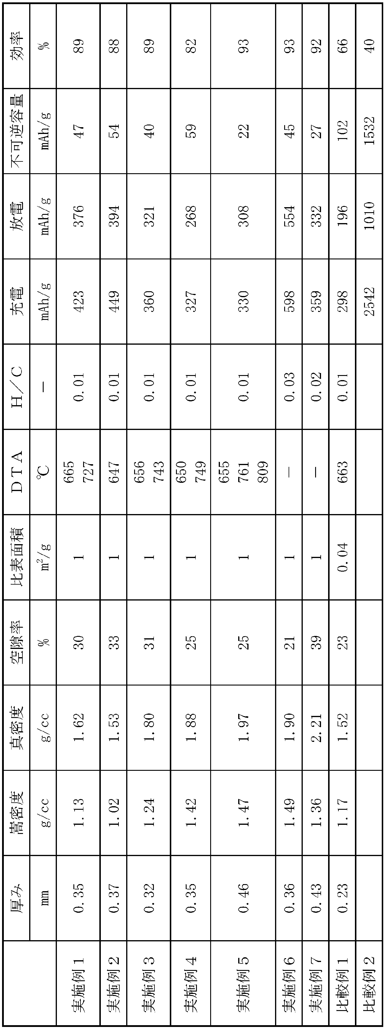
以上、本発明を特定の態様に沿って説明したが、当業者に自明の変形や改良は本発明の範囲に含まれる。
Claims (14)
- リチウムがドープ及び脱ドープできる炭素繊維及び炭素質材料を含む電池電極用炭素質成形体であって、厚さが1mm以下、元素分析による水素原子と炭素原子との原子比(H/C)が0.1以下、成形体の嵩密度とブタノール真密度から求められる空隙率が25~80%、そして揮発分が5.0重量%以下であることを特徴とする電池電極用炭素質成形体。
- 前記炭素質材料が難黒鉛化性炭素質材料である、請求項1に記載の電池電極用炭素質成形体。
- 前記炭素質材料が易黒鉛化性炭素質材料である、請求項1又は2に記載の電池電極用炭素質成形体。
- リチウムを挿入及び脱離可能な金属及びリチウムを挿入及び脱離可能な金属化合物からなる群から選択される1つ以上の負極活物質を更に含む、請求項1~3のいずれか一項に記載の電池電極用炭素質成形体。
- 真密度が1.4~2.20g/cm3である、請求項1~4のいずれか一項に記載の電池電極用炭素質成形体。
- 示差熱分析装置による測定で、燃焼ピークが760℃以下に少なくとも1本以上観測される、請求項1~5のいずれか一項に記載の電池電極用炭素質成形体。
- 前記炭素繊維が等方性構造を有する、請求項1~6のいずれか一項に記載の電池電極用炭素質成形体。
- 請求項1~7のいずれか一項に記載の電池電極用炭素質成形体を含む、電池用電極。
- 請求項8に記載の電池用電極を含む非水電解質二次電池。
- (1)リチウムがドープ及び脱ドープできる炭素繊維及び/又はその炭素繊維前駆体、及び炭素質前駆体を混合し、混合物を得る工程、
(2)前記混合物を成形し、成形体を得る工程、
(3)前記成形体を、非酸化性ガス雰囲気下1000℃~2000℃で熱処理する焼成工程、
を含む、電池電極用炭素質成形体の製造方法。 - 前記炭素質前駆体が難黒鉛化性炭素質前駆体及び/又は易黒鉛化性炭素質前駆体である、請求項10に記載の電池電極用炭素質成形体の製造方法。
- 前記工程(1)において、リチウムを挿入及び脱離可能な金属及びリチウムを挿入及び脱離可能な金属化合物からなる群から選択される1つ以上の負極活物質を更に混合する、請求項10又は11に記載の電池電極用炭素質成形体の製造方法。
- 前記成形工程(2)における成形体が、圧縮成形により得られるものである、請求項10~12のいずれか一項に記載の電池電極用炭素質成形体の製造方法。
- 前記炭素繊維が等方性構造を有する請求項10~13のいずれか一項に記載の電池電極用炭素質成形体の製造方法。
Priority Applications (2)
| Application Number | Priority Date | Filing Date | Title |
|---|---|---|---|
| US15/562,152 US20180083282A1 (en) | 2015-03-27 | 2016-03-28 | Carbonaceous molded body for battery electrode and method of manufacturing same |
| JP2017509952A JP6297746B2 (ja) | 2015-03-27 | 2016-03-28 | 電池電極用炭素質成形体、及びその製造方法 |
Applications Claiming Priority (2)
| Application Number | Priority Date | Filing Date | Title |
|---|---|---|---|
| JP2015-067561 | 2015-03-27 | ||
| JP2015067561 | 2015-03-27 |
Publications (1)
| Publication Number | Publication Date |
|---|---|
| WO2016158823A1 true WO2016158823A1 (ja) | 2016-10-06 |
Family
ID=57007102
Family Applications (1)
| Application Number | Title | Priority Date | Filing Date |
|---|---|---|---|
| PCT/JP2016/059832 Ceased WO2016158823A1 (ja) | 2015-03-27 | 2016-03-28 | 電池電極用炭素質成形体、及びその製造方法 |
Country Status (3)
| Country | Link |
|---|---|
| US (1) | US20180083282A1 (ja) |
| JP (1) | JP6297746B2 (ja) |
| WO (1) | WO2016158823A1 (ja) |
Cited By (2)
| Publication number | Priority date | Publication date | Assignee | Title |
|---|---|---|---|---|
| WO2017056991A1 (ja) * | 2015-09-30 | 2017-04-06 | 株式会社クレハ | ナトリウムイオン二次電池負極用炭素質材料及びそれを用いたナトリウムイオン二次電池 |
| JP2020149824A (ja) * | 2019-03-12 | 2020-09-17 | トヨタ自動車株式会社 | リチウムイオン二次電池及びその製造方法 |
Families Citing this family (5)
| Publication number | Priority date | Publication date | Assignee | Title |
|---|---|---|---|---|
| US20160159009A1 (en) * | 2014-12-05 | 2016-06-09 | Philip L. Canale | Combined thermal and uv/visible light curing stereolithography |
| US11289700B2 (en) | 2016-06-28 | 2022-03-29 | The Research Foundation For The State University Of New York | KVOPO4 cathode for sodium ion batteries |
| CN110660955B (zh) * | 2018-06-29 | 2021-11-23 | 宁德时代新能源科技股份有限公司 | 负极极片、其制备方法及电化学装置 |
| US11426818B2 (en) | 2018-08-10 | 2022-08-30 | The Research Foundation for the State University | Additive manufacturing processes and additively manufactured products |
| CN115275085B (zh) * | 2022-06-10 | 2025-10-03 | 宁波杉杉新材料科技有限公司 | 石墨负极材料及其制备方法、应用、锂离子电池 |
Citations (6)
| Publication number | Priority date | Publication date | Assignee | Title |
|---|---|---|---|---|
| JPH0992283A (ja) * | 1995-09-19 | 1997-04-04 | Petoca:Kk | 非水リチウム二次電池用炭素材及びその製造方法 |
| JPH10284089A (ja) * | 1997-04-03 | 1998-10-23 | Sony Corp | 非水溶媒系二次電池の電極用炭素質材料及びその製造方法、並びに非水溶媒系二次電池 |
| JP2009146580A (ja) * | 2007-12-11 | 2009-07-02 | Osaka Gas Chem Kk | リチウムイオン二次電池用負極活物質シート及びその製造方法 |
| WO2013118757A1 (ja) * | 2012-02-06 | 2013-08-15 | 株式会社クレハ | 非水電解質二次電池用炭素質材料 |
| JP2014029848A (ja) * | 2012-06-29 | 2014-02-13 | Jfe Chemical Corp | リチウムイオン二次電池負極用複合粒子及びその製造方法、リチウムイオン二次電池用負極並びにリチウムイオン二次電池 |
| JP5619321B2 (ja) * | 2012-08-30 | 2014-11-05 | 株式会社クレハ | 非水電解質二次電池用炭素質材料及びその製造方法、並びに前記炭素質材料を用いた負極および非水電解質二次電池 |
Family Cites Families (5)
| Publication number | Priority date | Publication date | Assignee | Title |
|---|---|---|---|---|
| JPH0722022A (ja) * | 1993-06-30 | 1995-01-24 | Nippon Steel Corp | リチウム二次電池用負極とその製造方法 |
| JP4244041B2 (ja) * | 2005-04-07 | 2009-03-25 | シャープ株式会社 | リチウムイオン二次電池及びその製造方法 |
| WO2010134465A1 (ja) * | 2009-05-18 | 2010-11-25 | 旭硝子株式会社 | 含フッ素結着剤 |
| JP5841420B2 (ja) * | 2010-12-09 | 2016-01-13 | 出光興産株式会社 | リチウム二次電池電極用スラリー組成物及びそれを用いた電池 |
| JP6358256B2 (ja) * | 2013-09-03 | 2018-07-18 | 日本ゼオン株式会社 | リチウムイオン二次電池負極用スラリー組成物、リチウムイオン二次電池負極の製造方法及びリチウムイオン二次電池 |
-
2016
- 2016-03-28 WO PCT/JP2016/059832 patent/WO2016158823A1/ja not_active Ceased
- 2016-03-28 US US15/562,152 patent/US20180083282A1/en not_active Abandoned
- 2016-03-28 JP JP2017509952A patent/JP6297746B2/ja not_active Expired - Fee Related
Patent Citations (6)
| Publication number | Priority date | Publication date | Assignee | Title |
|---|---|---|---|---|
| JPH0992283A (ja) * | 1995-09-19 | 1997-04-04 | Petoca:Kk | 非水リチウム二次電池用炭素材及びその製造方法 |
| JPH10284089A (ja) * | 1997-04-03 | 1998-10-23 | Sony Corp | 非水溶媒系二次電池の電極用炭素質材料及びその製造方法、並びに非水溶媒系二次電池 |
| JP2009146580A (ja) * | 2007-12-11 | 2009-07-02 | Osaka Gas Chem Kk | リチウムイオン二次電池用負極活物質シート及びその製造方法 |
| WO2013118757A1 (ja) * | 2012-02-06 | 2013-08-15 | 株式会社クレハ | 非水電解質二次電池用炭素質材料 |
| JP2014029848A (ja) * | 2012-06-29 | 2014-02-13 | Jfe Chemical Corp | リチウムイオン二次電池負極用複合粒子及びその製造方法、リチウムイオン二次電池用負極並びにリチウムイオン二次電池 |
| JP5619321B2 (ja) * | 2012-08-30 | 2014-11-05 | 株式会社クレハ | 非水電解質二次電池用炭素質材料及びその製造方法、並びに前記炭素質材料を用いた負極および非水電解質二次電池 |
Cited By (4)
| Publication number | Priority date | Publication date | Assignee | Title |
|---|---|---|---|---|
| WO2017056991A1 (ja) * | 2015-09-30 | 2017-04-06 | 株式会社クレハ | ナトリウムイオン二次電池負極用炭素質材料及びそれを用いたナトリウムイオン二次電池 |
| JPWO2017056991A1 (ja) * | 2015-09-30 | 2018-08-30 | 株式会社クラレ | ナトリウムイオン二次電池負極用炭素質材料及びそれを用いたナトリウムイオン二次電池 |
| JP2020149824A (ja) * | 2019-03-12 | 2020-09-17 | トヨタ自動車株式会社 | リチウムイオン二次電池及びその製造方法 |
| JP7096184B2 (ja) | 2019-03-12 | 2022-07-05 | トヨタ自動車株式会社 | リチウムイオン二次電池及びその製造方法 |
Also Published As
| Publication number | Publication date |
|---|---|
| US20180083282A1 (en) | 2018-03-22 |
| JP6297746B2 (ja) | 2018-03-20 |
| JPWO2016158823A1 (ja) | 2017-10-26 |
Similar Documents
| Publication | Publication Date | Title |
|---|---|---|
| JP6279713B2 (ja) | 電極用炭素質成形体、及びその製造方法 | |
| KR101633206B1 (ko) | 리튬 이온 이차 전지용 부극 재료, 리튬 이온 이차 전지용 부극 및 리튬 이온 이차 전지 | |
| KR101461220B1 (ko) | 리튬 이차 전지용 음극 활물질, 이의 제조 방법, 그리고 이를 포함하는 음극 및 리튬 이차 전지 | |
| JP5960053B2 (ja) | リチウム二次電池用負極活物質 | |
| KR101494715B1 (ko) | 리튬 이차 전지용 음극 활물질, 이의 제조 방법, 그리고 이를 포함하는 음극 및 리튬 이차 전지 | |
| JP5225690B2 (ja) | 複合黒鉛粒子及びそれを用いたリチウム二次電池 | |
| JP5563578B2 (ja) | 複合黒鉛粒子及びそれを用いたリチウム二次電池 | |
| JP6297746B2 (ja) | 電池電極用炭素質成形体、及びその製造方法 | |
| JP6367925B2 (ja) | 全固体電池用負極及びそれを含む全固体電池 | |
| KR101504614B1 (ko) | 리튬이차전지용 흑연계 음극활물질 | |
| KR20140140323A (ko) | 리튬 이차 전지용 음극 활물질, 이의 제조 방법 및 이를 포함하는 리튬 이차전지 | |
| KR20150063620A (ko) | 리튬 이차 전지용 음극 활물질, 이의 제조 방법 및 이를 포함하는 리튬 이차 전지 | |
| JP2019175851A (ja) | リチウムイオン二次電池用負極活物質及びその製造方法 | |
| JP4045438B2 (ja) | 二次電池用の二層炭素材料及びそれを用いたリチウム二次電池 | |
| JP4933092B2 (ja) | リチウムイオン二次電池用負極材料、リチウムイオン二次電池用負極およびリチウムイオン二次電池 | |
| JP2017183205A (ja) | リチウム二次電池負極用材料及びその製造方法 | |
| JP2007031233A (ja) | 黒鉛材料の製造方法 | |
| JP5001977B2 (ja) | 黒鉛質粒子、リチウムイオン二次電池およびその負極材料 | |
| JP2016157648A (ja) | 非水電解質二次電池 | |
| CN119852399B (zh) | 碳基负极活性材料、制备方法、二次电池和用电装置 |
Legal Events
| Date | Code | Title | Description |
|---|---|---|---|
| 121 | Ep: the epo has been informed by wipo that ep was designated in this application |
Ref document number: 16772704 Country of ref document: EP Kind code of ref document: A1 |
|
| ENP | Entry into the national phase |
Ref document number: 2017509952 Country of ref document: JP Kind code of ref document: A |
|
| WWE | Wipo information: entry into national phase |
Ref document number: 15562152 Country of ref document: US |
|
| NENP | Non-entry into the national phase |
Ref country code: DE |
|
| 122 | Ep: pct application non-entry in european phase |
Ref document number: 16772704 Country of ref document: EP Kind code of ref document: A1 |