WO2016158771A1 - 車両搭載型クレーン用旋回ポスト - Google Patents
車両搭載型クレーン用旋回ポスト Download PDFInfo
- Publication number
- WO2016158771A1 WO2016158771A1 PCT/JP2016/059665 JP2016059665W WO2016158771A1 WO 2016158771 A1 WO2016158771 A1 WO 2016158771A1 JP 2016059665 W JP2016059665 W JP 2016059665W WO 2016158771 A1 WO2016158771 A1 WO 2016158771A1
- Authority
- WO
- WIPO (PCT)
- Prior art keywords
- vehicle
- side plate
- portions
- plate portions
- pair
- Prior art date
- Legal status (The legal status is an assumption and is not a legal conclusion. Google has not performed a legal analysis and makes no representation as to the accuracy of the status listed.)
- Ceased
Links
Images


Classifications
-
- B—PERFORMING OPERATIONS; TRANSPORTING
- B66—HOISTING; LIFTING; HAULING
- B66C—CRANES; LOAD-ENGAGING ELEMENTS OR DEVICES FOR CRANES, CAPSTANS, WINCHES, OR TACKLES
- B66C23/00—Cranes comprising essentially a beam, boom, or triangular structure acting as a cantilever and mounted for translatory of swinging movements in vertical or horizontal planes or a combination of such movements, e.g. jib-cranes, derricks, tower cranes
- B66C23/06—Cranes comprising essentially a beam, boom, or triangular structure acting as a cantilever and mounted for translatory of swinging movements in vertical or horizontal planes or a combination of such movements, e.g. jib-cranes, derricks, tower cranes with jibs mounted for jibbing or luffing movements
-
- B—PERFORMING OPERATIONS; TRANSPORTING
- B66—HOISTING; LIFTING; HAULING
- B66C—CRANES; LOAD-ENGAGING ELEMENTS OR DEVICES FOR CRANES, CAPSTANS, WINCHES, OR TACKLES
- B66C23/00—Cranes comprising essentially a beam, boom, or triangular structure acting as a cantilever and mounted for translatory of swinging movements in vertical or horizontal planes or a combination of such movements, e.g. jib-cranes, derricks, tower cranes
- B66C23/16—Cranes comprising essentially a beam, boom, or triangular structure acting as a cantilever and mounted for translatory of swinging movements in vertical or horizontal planes or a combination of such movements, e.g. jib-cranes, derricks, tower cranes with jibs supported by columns, e.g. towers having their lower end mounted for slewing movements
- B66C23/166—Simple cranes with jibs which may be fixed or can slew or luff
-
- B—PERFORMING OPERATIONS; TRANSPORTING
- B66—HOISTING; LIFTING; HAULING
- B66C—CRANES; LOAD-ENGAGING ELEMENTS OR DEVICES FOR CRANES, CAPSTANS, WINCHES, OR TACKLES
- B66C23/00—Cranes comprising essentially a beam, boom, or triangular structure acting as a cantilever and mounted for translatory of swinging movements in vertical or horizontal planes or a combination of such movements, e.g. jib-cranes, derricks, tower cranes
- B66C23/18—Cranes comprising essentially a beam, boom, or triangular structure acting as a cantilever and mounted for translatory of swinging movements in vertical or horizontal planes or a combination of such movements, e.g. jib-cranes, derricks, tower cranes specially adapted for use in particular purposes
- B66C23/36—Cranes comprising essentially a beam, boom, or triangular structure acting as a cantilever and mounted for translatory of swinging movements in vertical or horizontal planes or a combination of such movements, e.g. jib-cranes, derricks, tower cranes specially adapted for use in particular purposes mounted on road or rail vehicles; Manually-movable jib-cranes for use in workshops; Floating cranes
- B66C23/44—Jib-cranes adapted for attachment to standard vehicles, e.g. agricultural tractors
-
- B—PERFORMING OPERATIONS; TRANSPORTING
- B66—HOISTING; LIFTING; HAULING
- B66C—CRANES; LOAD-ENGAGING ELEMENTS OR DEVICES FOR CRANES, CAPSTANS, WINCHES, OR TACKLES
- B66C23/00—Cranes comprising essentially a beam, boom, or triangular structure acting as a cantilever and mounted for translatory of swinging movements in vertical or horizontal planes or a combination of such movements, e.g. jib-cranes, derricks, tower cranes
- B66C23/62—Constructional features or details
-
- B—PERFORMING OPERATIONS; TRANSPORTING
- B66—HOISTING; LIFTING; HAULING
- B66C—CRANES; LOAD-ENGAGING ELEMENTS OR DEVICES FOR CRANES, CAPSTANS, WINCHES, OR TACKLES
- B66C23/00—Cranes comprising essentially a beam, boom, or triangular structure acting as a cantilever and mounted for translatory of swinging movements in vertical or horizontal planes or a combination of such movements, e.g. jib-cranes, derricks, tower cranes
- B66C23/62—Constructional features or details
- B66C23/64—Jibs
- B66C23/70—Jibs constructed of sections adapted to be assembled to form jibs or various lengths
- B66C23/701—Jibs constructed of sections adapted to be assembled to form jibs or various lengths telescopic
- B66C23/705—Jibs constructed of sections adapted to be assembled to form jibs or various lengths telescopic telescoped by hydraulic jacks
-
- B—PERFORMING OPERATIONS; TRANSPORTING
- B66—HOISTING; LIFTING; HAULING
- B66C—CRANES; LOAD-ENGAGING ELEMENTS OR DEVICES FOR CRANES, CAPSTANS, WINCHES, OR TACKLES
- B66C23/00—Cranes comprising essentially a beam, boom, or triangular structure acting as a cantilever and mounted for translatory of swinging movements in vertical or horizontal planes or a combination of such movements, e.g. jib-cranes, derricks, tower cranes
- B66C23/62—Constructional features or details
- B66C23/72—Counterweights or supports for balancing lifting couples
- B66C23/78—Supports, e.g. outriggers, for mobile cranes
- B66C23/80—Supports, e.g. outriggers, for mobile cranes hydraulically actuated
-
- B—PERFORMING OPERATIONS; TRANSPORTING
- B66—HOISTING; LIFTING; HAULING
- B66C—CRANES; LOAD-ENGAGING ELEMENTS OR DEVICES FOR CRANES, CAPSTANS, WINCHES, OR TACKLES
- B66C23/00—Cranes comprising essentially a beam, boom, or triangular structure acting as a cantilever and mounted for translatory of swinging movements in vertical or horizontal planes or a combination of such movements, e.g. jib-cranes, derricks, tower cranes
- B66C23/62—Constructional features or details
- B66C23/82—Luffing gear
- B66C23/821—Bracing equipment for booms
- B66C23/823—Bracing equipment acting in vertical direction
-
- B—PERFORMING OPERATIONS; TRANSPORTING
- B66—HOISTING; LIFTING; HAULING
- B66C—CRANES; LOAD-ENGAGING ELEMENTS OR DEVICES FOR CRANES, CAPSTANS, WINCHES, OR TACKLES
- B66C23/00—Cranes comprising essentially a beam, boom, or triangular structure acting as a cantilever and mounted for translatory of swinging movements in vertical or horizontal planes or a combination of such movements, e.g. jib-cranes, derricks, tower cranes
- B66C23/62—Constructional features or details
- B66C23/84—Slewing gear
-
- B—PERFORMING OPERATIONS; TRANSPORTING
- B66—HOISTING; LIFTING; HAULING
- B66D—CAPSTANS; WINCHES; TACKLES, e.g. PULLEY BLOCKS; HOISTS
- B66D1/00—Rope, cable, or chain winding mechanisms; Capstans
Definitions
- the present invention relates to a turning post used for a vehicle-mounted crane.
- Patent Document 1 Conventionally, as a swing post used for a work vehicle having a boom, for example, a swing post shown in Patent Document 1 has been proposed.
- This turning post includes a bottom plate portion provided on a turntable of a work vehicle having a boom, and a pair of side plate portions provided extending upward from the left and right sides of the vehicle on the bottom plate portion.
- the pair of side plate portions is formed such that the upper portion has a wider interval between the side plate portions than the lower portion.
- each of the pair of side plate portions is formed of a hollow columnar body surrounded on four sides by a plate.
- the present invention has been made in view of such conventional problems, and an object of the present invention is to provide a vehicle-mounted crane turning post that can suppress an increase in size even when the width of the boom is increased.
- the turning post for a vehicle-mounted crane includes a bottom plate portion provided on a turntable of the vehicle-mounted crane and a pair of side plate portions provided to extend upward from the left and right sides of the vehicle on the bottom plate portion.
- the pair of side plate portions are each formed in a flat plate shape, and the upper portion is formed so that the interval between the side plate portions is wider than the lower portion.
- a portion where the support shaft for attaching the base end portion of the boom is disposed between the side plate portions at the upper portion has a wider interval between the side plate portions than the lower portion. It is preferable to be formed as described above.
- a portion where the winch drum is disposed between the side plate portions in the upper portion is formed so that a distance between the side plate portions is wider than the lower portion. Is preferred.
- each of the pair of side plate portions is formed in a flat plate shape, and the upper portion is formed so that the interval between the side plate portions is wider than the lower portion.
- the portion where the support shaft for attaching the base end portion of the boom is disposed between the side plate portions at the upper portion of the pair of side plate portions is wider than the lower portion.
- the support shaft can be reliably arranged at a desired position. Therefore, the vehicle-mounted crane turning post according to the present invention can reliably arrange the boom at a desired position while suppressing an increase in size even if the width of the boom is increased.
- the portion where the winch drum is disposed between the side plate portions at the upper portion of the pair of side plate portions is formed so that the interval between the side plate portions is wider than the lower portion.
- the winch drum can be easily disposed between the side plate portions.
- the turning post for a vehicle-mounted crane according to the present invention can prevent the wire winding performance from being lowered and the wire biting in even if the amount of wire winding increases.
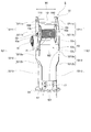
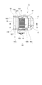
- FIG. 1 is a left side view of a vehicle-mounted crane to which a vehicle-mounted crane turning post according to an embodiment of the present invention is applied. It is the perspective view which looked at the turning post for vehicle-mounted cranes of the embodiment from the vehicle back side. It is a top view of the turning post for vehicle-mounted cranes of the embodiment.
- FIG. 4 is a cross-sectional view taken along line AA in FIG. 3.
- FIG. 1 is a left side view of a vehicle-mounted crane 1 to which a vehicle-mounted crane turning post 5 according to an embodiment of the present invention is applied.
- the vehicle-mounted crane 1 is simply referred to as a crane 1.
- the turning post 5 for a vehicle-mounted crane is simply referred to as a turning post 5.
- This crane 1 is installed on the swivel base 4, a car body 2 having a traveling function, an outrigger 3 provided on the front left and right of the car body 2, a swivel base 4 attached to the car body 2 so as to be horizontally turnable.
- the swivel post 5 according to the present embodiment and a boom 6 attached to the swivel post 5 so as to be raised and lowered are provided.
- the outrigger 3 prevents the crane 1 from overturning, and is overhanged and grounded by hydraulic pressure.
- the swivel base 4 is swiveled integrally with the boom 6 by a swivel drive device (not shown) provided on the vehicle body 2.
- the boom 6 is composed of a base boom 6a, intermediate booms 6b to 6c, and a tip boom 6d, and is telescopically driven by an expansion / contraction cylinder (not shown).
- the proximal boom 6a is pivotally attached to a support shaft 10 (see FIG. 2) installed horizontally on the swivel post 5 at the base thereof, and can be raised and lowered up and down.
- a hoisting cylinder 11 is bridged between the swivel post 5 and the base end portion of the base end boom 6a, and the hoisting cylinder 11 is extended and contracted to drive the boom 6 as a whole.
- a rotatable sheave (not shown) is attached to the tip of the tip boom 6d, and a wire 12 is hung on the sheave.
- a hook 14 is attached to the tip of the wire 12 via a hook block 13.
- the end of the wire 12 is wound around a winch drum 15.
- the winch drum 15 is rotatably disposed in the turning post 5 as shown in FIG.
- the winch drum 15 is rotationally driven by a winch motor (not shown) provided in the turning post 5 via a reduction gear 16 provided outside the turning post 5.
- the speed reducer 16 reduces the number of rotations and transmits power to the winch drum 15. Accordingly, the winch drum 15 is rotationally driven in the winding direction or the lowering direction, and the wire 12 is wound or lowered, and thereby the hook 14 is raised or lowered.
- the vehicle body 2 is provided with a controller (not shown).
- This controller is used to perform operations related to the lifting work.
- this controller includes a turning lever, a telescopic operation lever, a hoisting operation lever, a winch operation lever, an outrigger extension / retraction operation switch, and the like. By operating these operation levers and operation switches, the turning drive device, the telescopic cylinder, the hoisting cylinder 11, the winch drum 15, the winch motor, and the outrigger 3 are operated.
- FIG. 2 is a perspective view of the turning post 5 as seen from the rear side of the vehicle.
- the turning post 5 includes a bottom plate portion 51 provided on the turntable 4 (see FIG. 1), a support portion 52 provided extending upward on the bottom plate portion 51, and a front side (vehicle rear side) of the support portion 52. ) Provided on the front plate portion 53.
- Bottom plate portion 51 The bottom plate portion 51 is formed in a flat plate shape. The bottom plate portion 51 is fixed to the upper surface of the turntable 4. A pair of attachment portions 17 for attaching the lower end of the undulation cylinder 11 is provided on the front side of the front plate portion 53 on the upper surface of the bottom plate portion 51.
- the support portion 52 supports the support shaft 10 and the winch drum 15 to which the base end portion of the boom 6 described above (the base end portion of the base end boom 6a) is attached.
- the support portion 52 is formed in a shape having an opening on the front side (vehicle rear side).
- the support portion 52 includes a pair of side plate portions 521 and 521 provided on the bottom plate portion 51 so as to extend upward from the left and right sides of the vehicle, and a rear side of the pair of side plate portions 521 and 521. And a rear plate portion 522 that joins the ends (vehicle front side ends).
- each of the pair of side plate portions 521 and 521 is formed in a flat plate shape by a single plate. Further, the pair of side plate portions 521 and 521 are formed such that the interval W1 between the upper portions 5211 and 5211 is wider than the interval W3 between the lower portions 5213 and 5213. This will be specifically described below.
- Lower portions 5213 and 5213 of the pair of side plate portions 521 and 521 are formed to extend vertically upward from the upper surface of the bottom plate portion 51.
- the intermediate portions 5212 and 5212 of the pair of side plate portions 521 and 521 extend upward from the upper ends of the swash plate portions 5212b and 5212b and the swash plate portions 5212b and 5212b extending obliquely upward from the upper ends of the lower portions 5213 and 5213 to the left and right sides of the vehicle.
- Vertical plate portions 5212a and 5212a extending vertically are provided.
- the interval W2 between the vertical plate portions 5212a and 5212a is wider than the interval W3 between the lower portions 5213 and 5213 due to the swash plate portions 5212b and 5212b.
- the upper parts 5211 and 5211 of the pair of side plate parts 521 and 521 are formed to extend vertically upward from the upper ends of the vertical plate parts 5212a and 5212a of the intermediate parts 5212 and 5212.
- the interval W2 between the vertical plate portions 5212a and 5212a is wider than the interval W3 between the lower portions 5213 and 5213
- the interval W1 between the upper portions 5211 and 5211 formed on the upper end side of the vertical plate portions 5212a and 5212a is lower portion 5213.
- 5213 is wider than the interval W3.
- the upper ends of the upper portions 5211 and 5211 constitute support shaft arrangement portions 5211a and 5211a in which the support shaft 10 is arranged therebetween.
- the support shaft arrangement portions 5211a and 5211a are provided with boss portions 110 and 110 inside thereof. Both ends of the support shaft 10 are attached to the boss portions 110 and 110 and are arranged between the support shaft arrangement portions 5211a and 5211a.
- the portions other than the support shaft arrangement parts 5211a and 5211a of the upper parts 5211 and 5211 constitute winch drum arrangement parts 5211b and 5211b in which the winch drum 15 is arranged therebetween.
- the winch drum arrangement portions 5211b and 5211b are provided with wire detachment stoppers 150 and 150 on the inner side thereof.
- the winch drum 15 has a trunk portion 15a and flange portions 15b and 15b formed on the left and right sides of the trunk portion 15a.
- the winch drum 15 is rotatably arranged between the winch drum arrangement portions 5211b and 5211b by the drum support shaft 20.
- speed reducer 16 described above is provided from the upper part 5211 of the left side plate part 521 to the outer side of the intermediate part 5212.
- the rear plate portion 522 is formed in a flat plate shape by a single plate as shown in FIGS. 3 and 4. In FIG. 4, the winch drum 15 is omitted.
- the front plate portion 53 is formed in a flat plate shape as shown in FIG.
- the front plate portion 53 includes a front plate upper portion 53a whose upper end is coupled to the rear plate portion 522, a front plate intermediate portion 53b whose upper end is coupled to the front plate upper portion 53a, and a lower end of the front plate intermediate portion 53b.
- a front plate lower side portion 53c having an upper end coupled and a lower end coupled to the bottom plate portion 51.
- the upper end of the front plate upper portion 53a is joined to the lower portion of the rear plate portion 522 from the support shaft 10, and is formed in an L shape forward (rear of the vehicle) and downward.
- the left and right sides of the front plate upper portion 53a are joined to the upper portions 5211 and 5211 of the pair of side plate portions 521 and 521, respectively.
- Boss portions 110 are arranged on the upper surface of the front plate upper portion 53a.
- the upper end of the front plate middle portion 53b is joined to the lower portion of the front plate upper portion 53a with respect to the winch drum 15, and is formed in an L shape forward (vehicle rear) and downward.
- the left and right sides of the front plate intermediate portion 53 b are joined to the intermediate portions 5212 and 5212 and the lower portions 5213 and 5213 of the pair of side plate portions 521 and 521.
- wire detachment stoppers 150 and 150 described above are provided on the left and right sides of the upper surface of the front plate middle portion 53b from the front surface (vehicle rear side surface) of the front plate upper portion 53a.
- the front plate portion 53 is joined to the rear plate portion 522 and the pair of side plate portions 521 and 521, so that a space S is formed inside the turning post 5.
- the space S is provided with the winch motor (not shown) described above.
- the turning post 5 includes a bottom plate portion 51 provided on the turntable 4 of the vehicle-mounted crane 1 and a pair of upper plates provided extending upward from the left and right sides of the vehicle on the bottom plate portion 51.
- Each of the pair of side plate portions 521 and 521 is formed in a flat plate shape, and the interval W1 between the side plate portions 521 and 521 is wider in the upper portions 5211 and 5211 than in the lower portions 5213 and 5213. Is formed.
- the entire width of the pair of side plate portions 521 and 521 can be suppressed as compared with the case where the pair of side plate portions 521 and 521 are each formed of a hollow columnar body surrounded by a plate on all four sides. Therefore, even if the width of the boom 6 is increased in order to increase the strength of the swivel post 5 of the present embodiment when the boom 6 is lengthened, the enlargement can be suppressed.
- the structures of the lower portions 5213 and 5213 of the side plate portions 521 and 521 are not changed, so that the arrangement of the turning bearing and the turning outer ring bolt constituting the turning device need not be changed.
- the support shaft 10 for attaching the base end portion of the boom 6 between the side plate portions 521 and 521 at the upper portions 5211 and 5211 of the side plate portions 521 and 521 ( The support shaft arrangement portion 5211a) is formed so that the interval W1 between the side plate portions 521 and 521 is wider than the lower portion 5213.
- the swing post 5 of the present embodiment can reliably arrange the boom 6 at a desired position while suppressing an increase in size even if the width of the boom 6 is increased.
- the space W1 between the side plate portions 521 and 521 is formed to be wider than the lower portions 5213 and 5213.
- the winch drum 15 can be easily disposed between the side plate portions 521 and 521. Therefore, even if the winding amount of the wire 12 increases as the boom 6 becomes longer and the number of hooks 14 increases, the number of winding layers of the wire 12 can be increased by arranging the winch drum 15 having a larger width. Can be suppressed. Therefore, even if the amount of winding of the wire 12 increases, the swivel post 5 of the present embodiment can prevent the winding property of the wire 12 from being lowered and the wire 12 from being bitten.
- each of the pair of side plate portions 521 and 521 is formed in a flat plate shape by a single plate, but may be formed in a flat plate shape by joining a plurality of plates.
- the support shaft arrangement part 5211a and the winch drum arrangement part 5211b are formed on the upper parts 5211 and 5211 of the pair of side plate parts 521 and 521, but either one may be used.
Landscapes
- Engineering & Computer Science (AREA)
- Mechanical Engineering (AREA)
- Life Sciences & Earth Sciences (AREA)
- Agronomy & Crop Science (AREA)
- Jib Cranes (AREA)
Abstract
Description
底板部51は平板状に形成されている。この底板部51は旋回台4の上面に固定されている。底板部51の上面において前板部53の前側には、起伏シリンダ11の下端を取り付ける一対の取付部17,17が設けられている。
支持部52は、上記で説明したブーム6の基端部(基端ブーム6aの基端部)を取り付ける支持軸10とウインチドラム15を支持するものである。この支持部52は、前方側(車両後方側)が開口した形状に形成されている。
一対の側板部521,521は、図2に示すように、各々が一枚板により平板状に形成されている。さらに一対の側板部521,521は、上部5211,5211間の間隔W1が下部5213,5213間の間隔W3よりも広くなるように形成されている。これについて以下に具体的に説明する。
後板部522は、図3と図4に示すように一枚板により平板状に形成されている。図4では、ウインチドラム15を省略している。
前板部53は、図4に示すように平板状に形成されている。この前板部53は、後板部522に上端が結合された前板上側部53aと、前板上側部53aに上端が結合された前板中間部53bと、前板中間部53bの下端に上端が結合されて下端が底板部51に結合された前板下側部53cとを備えている。
4 旋回台
5 車両搭載型クレーン用旋回ポスト
6 ブーム
10 支持軸
15 ウインチドラム
51 底板部
521 側板部
5211 側板部の上部
5211a 支持軸配置部
5211b ウインチドラム配置部
5213 側板部の下部
W1 間隔
Claims (3)
- 車両搭載型クレーンの旋回台上に設けられた底板部と、前記底板部上の車両左右側から上方に延びて設けられた一対の側板部とを備え、
前記一対の側板部は、各々が平板状に形成され、上部が下部よりも側板部間の間隔が広くなるように形成されていることを特徴とする車両搭載型クレーン用旋回ポスト。 - 請求項1に記載の車両搭載型クレーン用旋回ポストにおいて、
前記上部で前記側板部間にブームの基端部を取り付ける支持軸が配置される部分が前記下部よりも前記側板部間の間隔が広くなるように形成されていることを特徴とする車両搭載型クレーン用旋回ポスト。 - 請求項1または請求項2に記載の車両搭載型クレーン用旋回ポストにおいて、
前記上部で前記側板部間にウインチドラムが配置される部分が前記下部よりも前記側板部間の間隔が広くなるように形成されていることを特徴とする車両搭載型クレーン用旋回ポスト。
Priority Applications (4)
| Application Number | Priority Date | Filing Date | Title |
|---|---|---|---|
| KR1020177025347A KR20170116117A (ko) | 2015-03-31 | 2016-03-25 | 차량 탑재형 크레인용 선회 포스트 |
| CN201680017771.9A CN107406242A (zh) | 2015-03-31 | 2016-03-25 | 车辆搭载型起重机用回转柱 |
| KR1020197025412A KR102079907B1 (ko) | 2015-03-31 | 2016-03-25 | 차량 탑재형 크레인용 선회 포스트 |
| JP2017509914A JP6418321B2 (ja) | 2015-03-31 | 2016-03-25 | 車両搭載型クレーン用旋回ポスト |
Applications Claiming Priority (2)
| Application Number | Priority Date | Filing Date | Title |
|---|---|---|---|
| JP2015-072087 | 2015-03-31 | ||
| JP2015072087 | 2015-03-31 |
Publications (1)
| Publication Number | Publication Date |
|---|---|
| WO2016158771A1 true WO2016158771A1 (ja) | 2016-10-06 |
Family
ID=57006768
Family Applications (1)
| Application Number | Title | Priority Date | Filing Date |
|---|---|---|---|
| PCT/JP2016/059665 Ceased WO2016158771A1 (ja) | 2015-03-31 | 2016-03-25 | 車両搭載型クレーン用旋回ポスト |
Country Status (4)
| Country | Link |
|---|---|
| JP (1) | JP6418321B2 (ja) |
| KR (2) | KR102079907B1 (ja) |
| CN (2) | CN107406242A (ja) |
| WO (1) | WO2016158771A1 (ja) |
Families Citing this family (2)
| Publication number | Priority date | Publication date | Assignee | Title |
|---|---|---|---|---|
| US11200180B2 (en) * | 2020-01-31 | 2021-12-14 | Western Digital Technologies, Inc. | NVMe SGL bit bucket transfers |
| US12043525B1 (en) | 2022-07-06 | 2024-07-23 | Tanner E. Mart | Lifting apparatus mountable on a wall |
Citations (4)
| Publication number | Priority date | Publication date | Assignee | Title |
|---|---|---|---|---|
| JPS6015396A (ja) * | 1983-07-05 | 1985-01-26 | 株式会社加藤製作所 | クレ−ン装置 |
| JPS6223288U (ja) * | 1985-07-26 | 1987-02-12 | ||
| JPH1059698A (ja) * | 1996-08-21 | 1998-03-03 | Shin Meiwa Ind Co Ltd | 高所作業車 |
| JPH10266266A (ja) * | 1997-03-26 | 1998-10-06 | Aichi Corp | 旋回台 |
Family Cites Families (9)
| Publication number | Priority date | Publication date | Assignee | Title |
|---|---|---|---|---|
| JPS616704A (ja) | 1984-06-21 | 1986-01-13 | Omron Tateisi Electronics Co | プログラマブル・コントロ−ラ |
| CN201169506Y (zh) * | 2008-01-24 | 2008-12-24 | 周爱兴 | 车载式套筒旋转起吊装置 |
| JP5649870B2 (ja) * | 2010-08-20 | 2015-01-07 | 株式会社タダノ | 移動式クレーン |
| JP2012071965A (ja) * | 2010-09-29 | 2012-04-12 | Tadano Ltd | クレーンの操作装置及びクレーン |
| CN102923584B (zh) * | 2011-08-08 | 2014-12-10 | 长沙桑尼重工机械有限公司 | 具有智能操作控制系统的智能随车起重机 |
| CN202279647U (zh) * | 2011-08-17 | 2012-06-20 | 深圳市强保成机械有限公司 | 一种随车起重机的起重臂 |
| CN102491210A (zh) * | 2011-12-22 | 2012-06-13 | 上海三一科技有限公司 | 一种一体式的卷扬支架及包括该支架的起重机 |
| CN202766153U (zh) * | 2012-09-10 | 2013-03-06 | 沅江市振兴液压机械有限公司 | 龙门式液压折臂吊机的龙门立柱 |
| CN103879837A (zh) * | 2014-03-05 | 2014-06-25 | 安徽亚神电缆集团有限公司 | 一种宽度可调式卷筒支架 |
-
2016
- 2016-03-25 WO PCT/JP2016/059665 patent/WO2016158771A1/ja not_active Ceased
- 2016-03-25 CN CN201680017771.9A patent/CN107406242A/zh active Pending
- 2016-03-25 CN CN201910952987.XA patent/CN110790151B/zh active Active
- 2016-03-25 JP JP2017509914A patent/JP6418321B2/ja active Active
- 2016-03-25 KR KR1020197025412A patent/KR102079907B1/ko active Active
- 2016-03-25 KR KR1020177025347A patent/KR20170116117A/ko not_active Ceased
Patent Citations (4)
| Publication number | Priority date | Publication date | Assignee | Title |
|---|---|---|---|---|
| JPS6015396A (ja) * | 1983-07-05 | 1985-01-26 | 株式会社加藤製作所 | クレ−ン装置 |
| JPS6223288U (ja) * | 1985-07-26 | 1987-02-12 | ||
| JPH1059698A (ja) * | 1996-08-21 | 1998-03-03 | Shin Meiwa Ind Co Ltd | 高所作業車 |
| JPH10266266A (ja) * | 1997-03-26 | 1998-10-06 | Aichi Corp | 旋回台 |
Also Published As
| Publication number | Publication date |
|---|---|
| JP6418321B2 (ja) | 2018-11-07 |
| KR102079907B1 (ko) | 2020-02-20 |
| JPWO2016158771A1 (ja) | 2018-01-25 |
| KR20170116117A (ko) | 2017-10-18 |
| CN110790151B (zh) | 2021-07-27 |
| CN107406242A (zh) | 2017-11-28 |
| CN110790151A (zh) | 2020-02-14 |
| KR20190103494A (ko) | 2019-09-04 |
Similar Documents
| Publication | Publication Date | Title |
|---|---|---|
| WO2016129262A1 (ja) | クローラクレーンのカーボディウエイト支持装置 | |
| CN107117542A (zh) | 起重机 | |
| JP2008120525A (ja) | 伸縮ブーム付きクレーン装置 | |
| JP6418321B2 (ja) | 車両搭載型クレーン用旋回ポスト | |
| JP5121351B2 (ja) | 移動式クレーン | |
| JP6727545B2 (ja) | 移動式クレーンのフックブロック格納装置 | |
| JP3209342U (ja) | 移動式クレーン | |
| JP5121352B2 (ja) | 移動式クレーン | |
| JP2006206233A (ja) | 移動式クレーンの伸縮ブームの横撓み抑制装置 | |
| JP6220187B2 (ja) | クローラクレーン | |
| JP2006273530A (ja) | 移動式クレーン | |
| JP6180792B2 (ja) | 伸縮ブーム | |
| JP5121350B2 (ja) | 移動式クレーン | |
| JP6391460B2 (ja) | ウインチドラム | |
| JP2010137976A (ja) | 巻上ウインチ装置およびクレーン | |
| JP3215230U (ja) | ウインチの取付構造 | |
| JP7452399B2 (ja) | クレーン | |
| JP2002003172A (ja) | クローラクレーン | |
| JP2007290791A (ja) | クレーンの油圧回路システム | |
| JP7025692B2 (ja) | ブームヘッド | |
| JP7380296B2 (ja) | ワイヤロープ絡み付き防止冶具 | |
| JP2009143710A (ja) | 移動式クレーンの補助ジブ | |
| JP7326898B2 (ja) | 建設機械 | |
| JP2007106518A (ja) | 自走式クレーン | |
| JP2019196239A (ja) | カウンタウェイト位置変更装置及びクレーン |
Legal Events
| Date | Code | Title | Description |
|---|---|---|---|
| 121 | Ep: the epo has been informed by wipo that ep was designated in this application |
Ref document number: 16772652 Country of ref document: EP Kind code of ref document: A1 |
|
| ENP | Entry into the national phase |
Ref document number: 20177025347 Country of ref document: KR Kind code of ref document: A |
|
| ENP | Entry into the national phase |
Ref document number: 2017509914 Country of ref document: JP Kind code of ref document: A |
|
| NENP | Non-entry into the national phase |
Ref country code: DE |
|
| 122 | Ep: pct application non-entry in european phase |
Ref document number: 16772652 Country of ref document: EP Kind code of ref document: A1 |