WO2016158569A1 - ブレーキ制御装置 - Google Patents
ブレーキ制御装置 Download PDFInfo
- Publication number
- WO2016158569A1 WO2016158569A1 PCT/JP2016/058986 JP2016058986W WO2016158569A1 WO 2016158569 A1 WO2016158569 A1 WO 2016158569A1 JP 2016058986 W JP2016058986 W JP 2016058986W WO 2016158569 A1 WO2016158569 A1 WO 2016158569A1
- Authority
- WO
- WIPO (PCT)
- Prior art keywords
- thrust
- electric motor
- vehicle
- pressing member
- parking brake
- Prior art date
- Legal status (The legal status is an assumption and is not a legal conclusion. Google has not performed a legal analysis and makes no representation as to the accuracy of the status listed.)
- Ceased
Links
Images

Classifications
-
- B—PERFORMING OPERATIONS; TRANSPORTING
- B60—VEHICLES IN GENERAL
- B60T—VEHICLE BRAKE CONTROL SYSTEMS OR PARTS THEREOF; BRAKE CONTROL SYSTEMS OR PARTS THEREOF, IN GENERAL; ARRANGEMENT OF BRAKING ELEMENTS ON VEHICLES IN GENERAL; PORTABLE DEVICES FOR PREVENTING UNWANTED MOVEMENT OF VEHICLES; VEHICLE MODIFICATIONS TO FACILITATE COOLING OF BRAKES
- B60T8/00—Arrangements for adjusting wheel-braking force to meet varying vehicular or ground-surface conditions, e.g. limiting or varying distribution of braking force
- B60T8/17—Using electrical or electronic regulation means to control braking
- B60T8/172—Determining control parameters used in the regulation, e.g. by calculations involving measured or detected parameters
-
- B—PERFORMING OPERATIONS; TRANSPORTING
- B60—VEHICLES IN GENERAL
- B60T—VEHICLE BRAKE CONTROL SYSTEMS OR PARTS THEREOF; BRAKE CONTROL SYSTEMS OR PARTS THEREOF, IN GENERAL; ARRANGEMENT OF BRAKING ELEMENTS ON VEHICLES IN GENERAL; PORTABLE DEVICES FOR PREVENTING UNWANTED MOVEMENT OF VEHICLES; VEHICLE MODIFICATIONS TO FACILITATE COOLING OF BRAKES
- B60T13/00—Transmitting braking action from initiating means to ultimate brake actuator with power assistance or drive; Brake systems incorporating such transmitting means, e.g. air-pressure brake systems
- B60T13/10—Transmitting braking action from initiating means to ultimate brake actuator with power assistance or drive; Brake systems incorporating such transmitting means, e.g. air-pressure brake systems with fluid assistance, drive, or release
- B60T13/58—Combined or convertible systems
- B60T13/585—Combined or convertible systems comprising friction brakes and retarders
- B60T13/586—Combined or convertible systems comprising friction brakes and retarders the retarders being of the electric type
-
- B—PERFORMING OPERATIONS; TRANSPORTING
- B60—VEHICLES IN GENERAL
- B60T—VEHICLE BRAKE CONTROL SYSTEMS OR PARTS THEREOF; BRAKE CONTROL SYSTEMS OR PARTS THEREOF, IN GENERAL; ARRANGEMENT OF BRAKING ELEMENTS ON VEHICLES IN GENERAL; PORTABLE DEVICES FOR PREVENTING UNWANTED MOVEMENT OF VEHICLES; VEHICLE MODIFICATIONS TO FACILITATE COOLING OF BRAKES
- B60T13/00—Transmitting braking action from initiating means to ultimate brake actuator with power assistance or drive; Brake systems incorporating such transmitting means, e.g. air-pressure brake systems
- B60T13/74—Transmitting braking action from initiating means to ultimate brake actuator with power assistance or drive; Brake systems incorporating such transmitting means, e.g. air-pressure brake systems with electrical assistance or drive
- B60T13/741—Transmitting braking action from initiating means to ultimate brake actuator with power assistance or drive; Brake systems incorporating such transmitting means, e.g. air-pressure brake systems with electrical assistance or drive acting on an ultimate actuator
-
- B—PERFORMING OPERATIONS; TRANSPORTING
- B60—VEHICLES IN GENERAL
- B60T—VEHICLE BRAKE CONTROL SYSTEMS OR PARTS THEREOF; BRAKE CONTROL SYSTEMS OR PARTS THEREOF, IN GENERAL; ARRANGEMENT OF BRAKING ELEMENTS ON VEHICLES IN GENERAL; PORTABLE DEVICES FOR PREVENTING UNWANTED MOVEMENT OF VEHICLES; VEHICLE MODIFICATIONS TO FACILITATE COOLING OF BRAKES
- B60T8/00—Arrangements for adjusting wheel-braking force to meet varying vehicular or ground-surface conditions, e.g. limiting or varying distribution of braking force
- B60T8/17—Using electrical or electronic regulation means to control braking
- B60T8/171—Detecting parameters used in the regulation; Measuring values used in the regulation
-
- B—PERFORMING OPERATIONS; TRANSPORTING
- B60—VEHICLES IN GENERAL
- B60T—VEHICLE BRAKE CONTROL SYSTEMS OR PARTS THEREOF; BRAKE CONTROL SYSTEMS OR PARTS THEREOF, IN GENERAL; ARRANGEMENT OF BRAKING ELEMENTS ON VEHICLES IN GENERAL; PORTABLE DEVICES FOR PREVENTING UNWANTED MOVEMENT OF VEHICLES; VEHICLE MODIFICATIONS TO FACILITATE COOLING OF BRAKES
- B60T8/00—Arrangements for adjusting wheel-braking force to meet varying vehicular or ground-surface conditions, e.g. limiting or varying distribution of braking force
- B60T8/17—Using electrical or electronic regulation means to control braking
- B60T8/1755—Brake regulation specially adapted to control the stability of the vehicle, e.g. taking into account yaw rate or transverse acceleration in a curve
-
- F—MECHANICAL ENGINEERING; LIGHTING; HEATING; WEAPONS; BLASTING
- F16—ENGINEERING ELEMENTS AND UNITS; GENERAL MEASURES FOR PRODUCING AND MAINTAINING EFFECTIVE FUNCTIONING OF MACHINES OR INSTALLATIONS; THERMAL INSULATION IN GENERAL
- F16D—COUPLINGS FOR TRANSMITTING ROTATION; CLUTCHES; BRAKES
- F16D55/00—Brakes with substantially-radial braking surfaces pressed together in axial direction, e.g. disc brakes
- F16D55/02—Brakes with substantially-radial braking surfaces pressed together in axial direction, e.g. disc brakes with axially-movable discs or pads pressed against axially-located rotating members
- F16D55/22—Brakes with substantially-radial braking surfaces pressed together in axial direction, e.g. disc brakes with axially-movable discs or pads pressed against axially-located rotating members by clamping an axially-located rotating disc between movable braking members, e.g. movable brake discs or brake pads
- F16D55/224—Brakes with substantially-radial braking surfaces pressed together in axial direction, e.g. disc brakes with axially-movable discs or pads pressed against axially-located rotating members by clamping an axially-located rotating disc between movable braking members, e.g. movable brake discs or brake pads with a common actuating member for the braking members
- F16D55/225—Brakes with substantially-radial braking surfaces pressed together in axial direction, e.g. disc brakes with axially-movable discs or pads pressed against axially-located rotating members by clamping an axially-located rotating disc between movable braking members, e.g. movable brake discs or brake pads with a common actuating member for the braking members the braking members being brake pads
- F16D55/226—Brakes with substantially-radial braking surfaces pressed together in axial direction, e.g. disc brakes with axially-movable discs or pads pressed against axially-located rotating members by clamping an axially-located rotating disc between movable braking members, e.g. movable brake discs or brake pads with a common actuating member for the braking members the braking members being brake pads in which the common actuating member is moved axially, e.g. floating caliper disc brakes
-
- F—MECHANICAL ENGINEERING; LIGHTING; HEATING; WEAPONS; BLASTING
- F16—ENGINEERING ELEMENTS AND UNITS; GENERAL MEASURES FOR PRODUCING AND MAINTAINING EFFECTIVE FUNCTIONING OF MACHINES OR INSTALLATIONS; THERMAL INSULATION IN GENERAL
- F16D—COUPLINGS FOR TRANSMITTING ROTATION; CLUTCHES; BRAKES
- F16D65/00—Parts or details
- F16D65/14—Actuating mechanisms for brakes; Means for initiating operation at a predetermined position
- F16D65/16—Actuating mechanisms for brakes; Means for initiating operation at a predetermined position arranged in or on the brake
- F16D65/18—Actuating mechanisms for brakes; Means for initiating operation at a predetermined position arranged in or on the brake adapted for drawing members together, e.g. for disc brakes
- F16D65/183—Actuating mechanisms for brakes; Means for initiating operation at a predetermined position arranged in or on the brake adapted for drawing members together, e.g. for disc brakes with force-transmitting members arranged side by side acting on a spot type force-applying member
-
- B—PERFORMING OPERATIONS; TRANSPORTING
- B60—VEHICLES IN GENERAL
- B60T—VEHICLE BRAKE CONTROL SYSTEMS OR PARTS THEREOF; BRAKE CONTROL SYSTEMS OR PARTS THEREOF, IN GENERAL; ARRANGEMENT OF BRAKING ELEMENTS ON VEHICLES IN GENERAL; PORTABLE DEVICES FOR PREVENTING UNWANTED MOVEMENT OF VEHICLES; VEHICLE MODIFICATIONS TO FACILITATE COOLING OF BRAKES
- B60T2220/00—Monitoring, detecting driver behaviour; Signalling thereof; Counteracting thereof
- B60T2220/04—Pedal travel sensor, stroke sensor; Sensing brake request
-
- B—PERFORMING OPERATIONS; TRANSPORTING
- B60—VEHICLES IN GENERAL
- B60T—VEHICLE BRAKE CONTROL SYSTEMS OR PARTS THEREOF; BRAKE CONTROL SYSTEMS OR PARTS THEREOF, IN GENERAL; ARRANGEMENT OF BRAKING ELEMENTS ON VEHICLES IN GENERAL; PORTABLE DEVICES FOR PREVENTING UNWANTED MOVEMENT OF VEHICLES; VEHICLE MODIFICATIONS TO FACILITATE COOLING OF BRAKES
- B60T2270/00—Further aspects of brake control systems not otherwise provided for
- B60T2270/89—Criteria for brake release
-
- F—MECHANICAL ENGINEERING; LIGHTING; HEATING; WEAPONS; BLASTING
- F16—ENGINEERING ELEMENTS AND UNITS; GENERAL MEASURES FOR PRODUCING AND MAINTAINING EFFECTIVE FUNCTIONING OF MACHINES OR INSTALLATIONS; THERMAL INSULATION IN GENERAL
- F16D—COUPLINGS FOR TRANSMITTING ROTATION; CLUTCHES; BRAKES
- F16D2121/00—Type of actuator operation force
- F16D2121/02—Fluid pressure
- F16D2121/04—Fluid pressure acting on a piston-type actuator, e.g. for liquid pressure
-
- F—MECHANICAL ENGINEERING; LIGHTING; HEATING; WEAPONS; BLASTING
- F16—ENGINEERING ELEMENTS AND UNITS; GENERAL MEASURES FOR PRODUCING AND MAINTAINING EFFECTIVE FUNCTIONING OF MACHINES OR INSTALLATIONS; THERMAL INSULATION IN GENERAL
- F16D—COUPLINGS FOR TRANSMITTING ROTATION; CLUTCHES; BRAKES
- F16D2121/00—Type of actuator operation force
- F16D2121/14—Mechanical
-
- F—MECHANICAL ENGINEERING; LIGHTING; HEATING; WEAPONS; BLASTING
- F16—ENGINEERING ELEMENTS AND UNITS; GENERAL MEASURES FOR PRODUCING AND MAINTAINING EFFECTIVE FUNCTIONING OF MACHINES OR INSTALLATIONS; THERMAL INSULATION IN GENERAL
- F16D—COUPLINGS FOR TRANSMITTING ROTATION; CLUTCHES; BRAKES
- F16D2121/00—Type of actuator operation force
- F16D2121/18—Electric or magnetic
- F16D2121/24—Electric or magnetic using motors
-
- F—MECHANICAL ENGINEERING; LIGHTING; HEATING; WEAPONS; BLASTING
- F16—ENGINEERING ELEMENTS AND UNITS; GENERAL MEASURES FOR PRODUCING AND MAINTAINING EFFECTIVE FUNCTIONING OF MACHINES OR INSTALLATIONS; THERMAL INSULATION IN GENERAL
- F16D—COUPLINGS FOR TRANSMITTING ROTATION; CLUTCHES; BRAKES
- F16D2125/00—Components of actuators
- F16D2125/02—Fluid-pressure mechanisms
- F16D2125/08—Seals, e.g. piston seals
-
- F—MECHANICAL ENGINEERING; LIGHTING; HEATING; WEAPONS; BLASTING
- F16—ENGINEERING ELEMENTS AND UNITS; GENERAL MEASURES FOR PRODUCING AND MAINTAINING EFFECTIVE FUNCTIONING OF MACHINES OR INSTALLATIONS; THERMAL INSULATION IN GENERAL
- F16D—COUPLINGS FOR TRANSMITTING ROTATION; CLUTCHES; BRAKES
- F16D2125/00—Components of actuators
- F16D2125/18—Mechanical mechanisms
- F16D2125/20—Mechanical mechanisms converting rotation to linear movement or vice versa
- F16D2125/34—Mechanical mechanisms converting rotation to linear movement or vice versa acting in the direction of the axis of rotation
- F16D2125/40—Screw-and-nut
Definitions
- the present invention relates to a brake control device that applies a braking force to a vehicle.
- Patent Document 1 As a brake device provided in a vehicle such as an automobile, an electric parking brake mechanism that operates based on driving of an electric motor is known (Patent Document 1).
- Patent Document 1 describes a technique for operating an ABS when an electric parking brake mechanism is operated while a vehicle is running and the parking brake is used as an auxiliary brake.
- the vehicle parking brake device disclosed in Patent Document 1 has a wheel slip rate that is unknown when the vehicle running state cannot be calculated due to a wheel speed sensor failure or the like. Power can be excessive.
- An object of the present invention is to provide a brake control device that can suppress an excessive application of braking force when the traveling state of a vehicle cannot be calculated.
- a brake control device includes a braking member that presses a braked member that rotates together with a wheel, and a pressing member that moves the braking member in a direction to come into contact with and separate from the braked member.
- a pressing member holding mechanism that is provided in a non-rotating part of the vehicle and holds the pressing member propelled by an electric motor, and an operation request signal for holding or releasing the pressing member according to a driver's operation instruction.
- a control unit that drives and controls the electric motor to move the pressing member in response to the operation request signal, and the control unit travels whether the vehicle is traveling or stopped.
- a travel state detection unit that calculates a state, and when the travel state cannot be calculated by the travel state detection unit, the time variation of the thrust of the pressing member is greater than when the travel state can be calculated. The rate is configured to control the electric motor so as to reduce.
- the brake control device of the present invention can suppress an excessive application of braking force when the traveling state of the vehicle cannot be calculated.
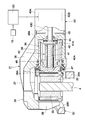
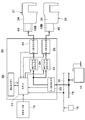
- the conceptual diagram of the vehicle carrying the brake control apparatus by embodiment The longitudinal cross-sectional view which expands and shows the disc brake with an electric parking brake function provided in the rear-wheel side in FIG.
- the block diagram which shows the parking brake control apparatus in FIG.
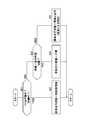
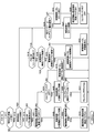
- the flowchart which shows the process which calculates the driving state of a vehicle.
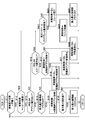
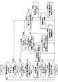
- the flowchart which shows the control processing at the time of driving state unknown by 1st Embodiment.
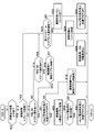
- the flowchart which shows the control processing at the time of driving state unknown by 2nd Embodiment.
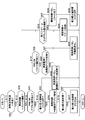
- the flowchart which shows the control processing at the time of driving state unknown by 4th Embodiment.
- the flowchart which shows the control processing at the time of driving state unknown by 5th Embodiment.
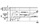
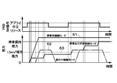
- the characteristic line figure which shows an example of operation of the parking brake switch by 5th Embodiment, and the time change of a thrust.
- the characteristic line figure which shows an example of operation of the parking brake switch by 1st Embodiment, and the time change of a thrust.
- the characteristic line figure which shows another example of operation of the parking brake switch by 1st Embodiment, and the time change of a thrust.
- step 1 is indicated as “S1”.
- FIG. 1 to 5 show a first embodiment.
- the front wheel 2 and the rear wheel 3 are provided with a disc rotor 4 as a braked member (rotating member) that rotates together with the respective wheels (the front wheels 2 and the rear wheels 3).
- the disc rotor 4 for the front wheel 2 is given a braking force by a hydraulic disc brake 5
- the disc rotor 4 for the rear wheel 3 is given a braking force by a hydraulic disc brake 31 with an electric parking brake function.
- The a braking force is applied to each wheel (each front wheel 2, each rear wheel 3) independently of each other.
- a brake pedal 6 is provided on the front board side of the vehicle body 1.
- the brake pedal 6 is depressed by the driver during the braking operation of the vehicle. Based on this operation, the disc brakes 5 and 31 are applied and released as a service brake (service brake).
- the brake pedal 6 is provided with a brake operation detection sensor (brake sensor) 6A such as a brake lamp switch, a pedal switch, and a pedal stroke sensor.
- the brake operation detection sensor 6 ⁇ / b> A detects whether or not the brake pedal 6 is depressed, or the operation amount thereof, and outputs a detection signal to the hydraulic pressure supply controller 13.
- the detection signal of the brake operation detection sensor 6A is transmitted via, for example, a vehicle data bus 16 or a signal line (not shown) connecting the hydraulic pressure supply device controller 13 and the parking brake control device 20 ( Output to the parking brake control device 20).
- the depression operation of the brake pedal 6 is transmitted via the booster 7 to the master cylinder 8 that functions as a hydraulic pressure source.
- the booster 7 is configured as a negative pressure booster or an electric booster provided between the brake pedal 6 and the master cylinder 8, and increases the pedal force when the brake pedal 6 is depressed and transmits it to the master cylinder 8.
- the master cylinder 8 generates hydraulic pressure with the brake fluid supplied from the master reservoir 9.
- the master reservoir 9 is composed of a hydraulic fluid tank that stores brake fluid.
- the mechanism for generating the hydraulic pressure by the brake pedal 6 is not limited to the above configuration, and a mechanism for generating the hydraulic pressure in response to the operation of the brake pedal 6, for example, a brake-by-wire mechanism or the like may be used. .
- the hydraulic pressure generated in the master cylinder 8 is sent to a hydraulic pressure supply device 11 (hereinafter referred to as ESC 11) via, for example, a pair of cylinder side hydraulic pipes 10A and 10B.
- the ESC 11 is disposed between each of the disc brakes 5, 31 and the master cylinder 8, and distributes the hydraulic pressure from the master cylinder 8 to each of the disc brakes 5, 31 via the brake side piping portions 12A, 12B, 12C, 12D. To do. Thereby, a braking force is applied to each of the wheels (each front wheel 2 and each rear wheel 3) independently of each other. In this case, even if the ESC 11 does not follow the operation amount of the brake pedal 6, the ESC 11 can supply the hydraulic pressure to the disc brakes 5, 31, that is, increase the hydraulic pressure of the disc brakes 5, 31.
- the ESC 11 has a dedicated control device constituted by, for example, a microcomputer, that is, a hydraulic pressure supply controller 13 (hereinafter referred to as a control unit 13).
- the control unit 13 performs drive control such as opening and closing each control valve (not shown) of the ESC 11 and rotating and stopping an electric motor (not shown) for the hydraulic pump.
- the control unit 13 performs control to increase, decrease or maintain the brake fluid pressure supplied to the disc brakes 5 and 31 from the brake side piping sections 12A to 12D.
- various brake controls such as boost control, braking force distribution control, brake assist control, antilock brake control (ABS), traction control, vehicle stabilization control (including skid prevention), slope start assist control, Automatic operation control or the like is executed.
- the power from the battery 14 is supplied to the control unit 13 through the power line 15. As shown in FIG. 1, the control unit 13 is connected to a vehicle data bus 16. A known ABS unit can be used instead of the ESC 11. Further, it is possible to directly connect the master cylinder 8 and the brake side piping sections 12A to 12D without providing the ESC 11 (that is, omitting them).
- the vehicle data bus 16 constitutes a CAN (Controller Area Network) as a serial communication unit mounted on the vehicle body 1.
- CAN Controller Area Network
- a large number of electronic devices mounted on the vehicle, the control unit 13, the parking brake control device 20, and the like perform multiplex communication within the vehicle.
- vehicle information sent to the vehicle data bus 16 includes, for example, a brake operation detection sensor 6A, a pressure sensor 17 for detecting a master cylinder hydraulic pressure (brake hydraulic pressure), an ignition switch, a seat belt sensor, a door lock sensor, Door opening sensor, seating sensor, vehicle speed sensor, steering angle sensor, accelerator sensor (accelerator operation sensor), throttle sensor, engine rotation sensor, stereo camera, millimeter wave radar, gradient sensor, shift sensor, acceleration sensor, wheel speed sensor 18, Information (vehicle information) by a detection signal from a pitch sensor or the like that detects the movement of the vehicle in the pitch direction can be given.
- the wheel speed sensor 18 is provided, for example, for each wheel (each front wheel 2, each rear wheel 3), and outputs a wheel signal corresponding to the rotation state (rotation speed) of each wheel 2, 3. It is.
- the parking brake control device 20 to be described later has a traveling state detection unit that calculates a traveling state as to whether the vehicle is traveling or stopped based on a wheel signal from the wheel speed sensor 18.
- the detection signal of the wheel speed sensor 18 is used as the wheel signal.
- the present invention is not limited to this.
- a signal having a correlation (correspondence) with the rotation state of the wheels 2 and 3 such as a detection signal of a vehicle speed sensor and a detection signal of an acceleration sensor is set according to the rotation state of the wheels 2 and 3 It may be used as a wheel signal.
- a parking brake switch (PKBSW) 19 is provided at a position near the driver's seat (not shown).
- the parking brake switch 19 serves as an operation instruction unit operated by the driver.
- the parking brake switch 19 generates a signal (operation request signal) corresponding to a parking brake operation request (an apply request that is a holding request, a release request that is a release request) in accordance with a driver's operation instruction.
- the parking brake switch 19 is used to apply (hold) or apply (release) the piston 39 and the brake pad 33 (see FIG. 2) based on the drive (rotation) of the electric motor 43B.
- An operation request signal (apply request signal, release request signal) is output to the parking brake control device 20 serving as a control unit (controller).
- the parking brake switch 19 When the driver operates the parking brake switch 19 to the braking side (apply side), that is, when there is an apply request (holding request, driving request) for applying braking force to the vehicle, the parking brake switch 19 An apply request signal is output.
- the electric power for rotating the electric motor 43B to the braking side is supplied to the disc brake 31 for the rear wheel 3 via the parking brake control device 20.
- the disc brake 31 for the rear wheel 3 is in a state where a braking force as a parking brake (or auxiliary brake) is applied, that is, in an applied state (holding state).
- the parking brake switch 19 When the parking brake switch 19 is operated to the brake release side (release side) by the driver, that is, when there is a release request (release request) for releasing the braking force of the vehicle, the parking brake switch 19 Outputs a release request signal. In this case, electric power for rotating the electric motor 43B in the direction opposite to the braking side is supplied to the disc brake 31 via the parking brake control device 20. As a result, the disc brake 31 for the rear wheel 3 is in a state where the application of the braking force as the parking brake (or auxiliary brake) is released, that is, in the released state (released state).
- the parking brake is used when, for example, the vehicle travels (for example, it is determined that the vehicle travels when the detection speed of the vehicle speed sensor is 5 km / h or more continues for a predetermined time as the vehicle speed increases from when the vehicle is stopped). Is operated, when the clutch pedal is operated, when the shift lever is operated other than P, N, etc., based on the automatic release request by the parking brake release determination logic in the parking brake control device 20 It can be configured to automatically release (auto release).
- a request for dynamic parking brake such as urgently using the parking brake as an auxiliary brake during traveling.
- a request for dynamic parking brake such as urgently using the parking brake as an auxiliary brake during traveling.
- the parking brake switch 19 when the parking brake switch 19 is operated to the braking side (while the operation to the braking side is continued), the braking force is applied, and when the operation is completed, the braking force is released. Is done.
- the parking brake control device 20 automatically applies and releases braking force (ABS control) depending on the state of the wheels (each rear wheel 3), that is, whether or not the wheels are locked (slip). It can also be set as the structure which performs.
- FIG. 2 only one of the left and right disc brakes 31, 31 provided corresponding to the left and right rear wheels 3, 3 is shown as a representative example.
- the pair of disc brakes 31 provided on the left and right sides of the vehicle are configured as hydraulic disc brakes provided with an electric parking brake function.
- the disc brake 31 forms a brake system together with the parking brake control device 20.
- the disc brake 31 includes a mounting member 32 attached to a non-rotating part on the rear wheel 3 side of the vehicle, an inner side and outer side brake pad 33 as a braking member (friction member), and a brake provided with an electric actuator 43. It includes a caliper 34 as a mechanism.
- the disc brake 31 extends the wheel (rear wheel 3) by propelling the brake pad 33 with the piston 39 by the hydraulic pressure based on the operation of the brake pedal 6 and the like, and pressing the disc rotor 4 with the brake pad 33. Applies braking force to the vehicle.
- the disc brake 31 is rotated (rotated) by the electric motor 43B in response to an operation request based on a signal from the parking brake switch 19, an application / release determination logic of the parking brake, and an operation request based on ABS control.
- the piston 39 is propelled (via the linear motion conversion mechanism 40) to apply a braking force to the vehicle.
- the disc brake 31 serves as a drive unit that performs an apply drive that applies a braking force to the vehicle by supplying a current to the electric motor 43B and a release drive that releases the braking force.
- the disc brake 31 is provided on each of the left and right wheels of the vehicle, in the embodiment, on the left and right rear wheels 3 and 3, respectively.
- the mounting member 32 includes a pair of arm portions (not shown), a support portion 32A, and a reinforcing beam 32B.
- the pair of arm portions extend in the axial direction of the disk rotor 4 (that is, the disk axial direction) so as to straddle the outer periphery of the disk rotor 4 and are separated from each other in the disk circumferential direction.
- the support portion 32A is formed to be relatively thick and is provided so as to integrally connect the base end sides of the respective arm portions, and is fixed to a non-rotating portion of the vehicle at a position on the inner side of the disc rotor 4.
- the reinforcing beam 32B is formed so as to connect the distal end sides of the respective arm portions to each other at a position on the outer side of the disk rotor 4.
- the inner and outer brake pads 33 are disposed so as to be able to contact both surfaces of the disk rotor 4 and supported by the respective arm portions of the mounting member 32 so as to be movable in the disk axial direction.
- the brake pads 33 on the inner side and the outer side are pressed against both sides of the disc rotor 4 by calipers 34 (the claw portions 38 and the pistons 39 of the caliper main body 35).
- the brake pad 33 gives a braking force to the vehicle by pressing the disc rotor 4 that rotates together with the wheels (rear wheels 3).
- the caliper 34 serving as a wheel cylinder is disposed on the mounting member 32 so as to straddle the outer peripheral side of the disc rotor 4.
- the caliper 34 is provided so as to be slidably inserted into the caliper body 35 supported so as to be movable along the axial direction of the disk rotor 4 with respect to each arm portion of the mounting member 32.
- a rotation / linear motion conversion mechanism 40, an electric actuator 43, and the like, which will be described later, are provided.
- the caliper 34 propels the brake pad 33 using a piston 39 that is operated by the hydraulic pressure generated in the master cylinder 8 based on the operation of the brake pedal 6.
- the caliper main body 35 includes an inner cylinder portion 36, a bridge portion 37, and an outer claw portion 38.
- the cylinder portion 36 is formed in a bottomed cylindrical shape in which one side in the axial direction is closed by a partition wall portion 36 ⁇ / b> A and the other side facing the disk rotor 4 is opened.
- the bridge portion 37 is formed to extend from the cylinder portion 36 in the disc axial direction so as to straddle the outer peripheral side of the disc rotor 4.
- the claw portion 38 is disposed so as to extend radially inward from the bridge portion 37 on the side opposite to the cylinder portion 36.
- the cylinder part 36 of the caliper main body 35 is supplied with hydraulic pressure accompanying the depression operation of the brake pedal 6 or the like via the brake side pipe part 12C or 12D shown in FIG.
- the cylinder portion 36 is integrally formed with the partition wall portion 36A.
- the partition wall portion 36 ⁇ / b> A is located between the cylinder portion 36 and the electric actuator 43.
- the partition wall portion 36A has a through hole in the axial direction, and an output shaft 43C of the electric actuator 43 is rotatably inserted on the inner peripheral side of the partition wall portion 36A.
- a piston 39 as a pressing member (moving member) and a rotation / linear motion conversion mechanism 40 are provided in the cylinder portion 36 of the caliper main body 35.
- the rotation / linear motion conversion mechanism 40 is accommodated in the piston 39.
- the rotation / linear motion conversion mechanism 40 may be configured to propel the piston 39 and may not necessarily be accommodated in the piston 39. That is, the rotation / linear motion conversion mechanism 40 serving as the pressing member holding mechanism may be provided at a non-rotating portion of the vehicle.
- the piston 39 moves the brake pad 33 in a direction in which the brake pad 33 is separated from or in contact with the disk rotor 4 (a direction toward the disk rotor 4 or a direction away from the disk rotor 4).
- the piston 39 is open on one side in the axial direction, and the other side in the axial direction facing the inner brake pad 33 is closed by a lid portion 39A.
- the piston 39 is inserted into the cylinder part 36.
- the hydraulic pressure is supplied into the cylinder portion 36 based on the depression of the brake pedal 6 or the like. Moving. In this case, the movement of the piston 39 by the electric actuator 43 (electric motor 43B) is performed by being pressed by the linear motion member.
- the rotation / linear motion conversion mechanism 40 is accommodated in a piston 39, and the piston 39 is configured to be propelled in the axial direction of the cylinder portion 36 by the rotation / linear motion conversion mechanism 40.
- Rotational linear motion conversion mechanism 40 functions as a pressing member holding mechanism. Specifically, the rotation / linear motion converting mechanism 40 propels the piston 39 with an external force different from the force generated by the addition of the hydraulic pressure into the cylinder portion 36, that is, the force generated by the electric actuator 43, and the propelled piston 39 and the brake pad 33 are held. Thereby, a parking brake will be in an applied state (holding state). On the other hand, the rotation / linear motion conversion mechanism 40 retracts the piston 39 in the direction opposite to the propulsion direction by the electric actuator 43, and sets the parking brake to the released state (released state). Since the left and right disc brakes 31 are respectively provided for the left and right rear wheels 3, the rotation / linear motion conversion mechanism 40 and the electric actuator 43 are also provided on each of the left and right sides of the vehicle.
- the rotation / linear motion conversion mechanism 40 includes a screw member 41 having a rod-like body in which a male screw such as a trapezoidal screw is formed, and a linear motion member 42 in which a female screw hole formed by the trapezoidal screw is formed on the inner peripheral side (spindle Configured as a nut mechanism).
- the linear motion member 42 is a driven member (propulsion member) that moves toward the piston 39 by the electric actuator 43 or in a direction away from the piston 39. That is, the screw member 41 screwed to the inner peripheral side of the linear motion member 42 constitutes a screw mechanism that converts the rotational motion by the electric actuator 43 into the linear motion of the linear motion member 42.
- the female screw of the linear motion member 42 and the male screw of the screw member 41 form a pressing member holding mechanism by using a highly irreversible screw, in the embodiment, a trapezoidal screw.
- the pressing member holding mechanism (rotation / linear motion converting mechanism 40) holds the linear motion member 42 (that is, the piston 39) at an arbitrary position by a frictional force (holding force) even when power supply to the electric motor 43B is stopped. It has become.
- the pressing member holding mechanism only needs to be able to hold the piston 39 at a position propelled by the electric actuator 43.
- the pressing member holding mechanism may be a normal triangular cross-section screw or a worm gear having a large irreversibility other than a trapezoidal screw.
- the screw member 41 that is screwed to the inner peripheral side of the linear motion member 42 is provided with a flange portion 41A that is a large-diameter flange on one side in the axial direction.
- the other side of the screw member 41 in the axial direction extends toward the lid portion 39 ⁇ / b> A of the piston 39.
- the screw member 41 is integrally connected to the output shaft 43C of the electric actuator 43 at the flange portion 41A.
- the linear motion member 42 is prevented from rotating with respect to the piston 39 (relative rotation is restricted), and the linear motion member 42 is allowed to relatively move in the axial direction.
- a protrusion 42A is provided. Thereby, the linear motion member 42 moves linearly when the electric motor 43B is driven, contacts the piston 39, and moves the piston 39.
- the electric actuator 43 is fixed to the caliper body 35 of the caliper 34.
- the electric actuator 43 operates (applies and releases) the disc brake 31 based on the operation request signal of the parking brake switch 19, the above-described parking brake apply / release determination logic, and ABS control.
- the electric actuator 43 includes a casing 43A, a speed reducer (not shown), an electric motor 43B, and an output shaft 43C.
- the casing 43A is attached to the outside of the partition wall portion 36A.
- the electric motor 43B is located in the casing 43A and includes a stator, a rotor, and the like, and moves the piston 39 when electric power (current) is supplied.
- a reduction gear (not shown) increases the torque of the electric motor 43B.
- the output shaft 43C is configured to output the increased rotational torque by the speed reducer.
- the electric motor 43B is configured as an electric motor such as a DC brush motor, for example.
- the output shaft 43C extends through the partition wall portion 36A of the cylinder portion 36 in the axial direction, and at the end of the flange portion 41A of the screw member 41 in the cylinder portion 36 so as to rotate integrally with the screw member 41. It is connected.
- the coupling mechanism between the output shaft 43C and the screw member 41 can be configured so as to be movable in the axial direction but prevented from rotating in the rotational direction, for example.
- a known technique such as spline fitting or fitting with a polygonal column (non-circular fitting) is used.
- the speed reducer for example, a planetary gear speed reducer or a worm gear speed reducer may be used.
- the reversible known mechanism such as a ball screw or a ball ramp mechanism is used as the rotation / linear motion converting mechanism 40.
- the pressing member holding mechanism can be configured by a reversible rotation / linear motion conversion mechanism and an irreversible speed reducer.
- the rotation / linear motion converting mechanism 40 when the screw member 41 is rotated relative to the linear motion member 42, the rotation of the linear motion member 42 in the piston 39 is restricted. For this reason, the linear motion member 42 relatively moves in the axial direction according to the rotation angle of the screw member 41. Thereby, the rotation / linear motion converting mechanism 40 converts the rotational motion into a linear motion, and the piston 39 is driven by the linear motion member 42. At the same time, the rotation / linear motion conversion mechanism 40 holds the linear motion member 42 at an arbitrary position by a frictional force with the screw member 41, so that the piston 39 and the brake pad 33 are propelled by the electric actuator 43. Hold on.
- a thrust bearing 44 is provided between the partition wall portion 36 ⁇ / b> A and the flange portion 41 ⁇ / b> A of the screw member 41 in the partition wall portion 36 ⁇ / b> A of the cylinder portion 36.
- the thrust bearing 44 receives a thrust load from the screw member 41 together with the partition wall portion 36A, and smoothly rotates the screw member 41 with respect to the partition wall portion 36A.
- a seal member 45 is provided between the partition wall portion 36A of the cylinder portion 36 and the output shaft 43C of the electric actuator 43. The seal member 45 leaks brake fluid in the cylinder portion 36 to the electric actuator 43 side. It seals between the two so as to prevent it.
- a piston seal 46 as an elastic seal that seals between the cylinder portion 36 and the piston 39 and a dust boot 47 that prevents foreign matter from entering the cylinder portion 36 are provided on the opening end side of the cylinder portion 36. It has been.
- the dust boot 47 is a flexible bellows-like seal member, and is attached between the opening end of the cylinder portion 36 and the outer periphery of the piston 39 on the lid portion 39A side.
- the disc brake 5 for the front wheel 2 is configured in substantially the same manner as the disc brake 31 for the rear wheel 3 except for the parking brake mechanism. That is, the disc brake 5 for the front wheel 2 does not include the rotation / linear motion conversion mechanism 40 that operates as a parking brake, the electric actuator 43, and the like provided in the disc brake 31 for the rear wheel 3. However, instead of the disc brake 5, a disc brake 31 with an electric parking brake function may be provided for the front wheel 2.
- the hydraulic disc brake 31 including the electric actuator 43 is described as an example of the brake device.
- a brake device that can press (promote) a braking member (pad, shoe) against a member to be braked (rotor, drum) based on driving of an electric actuator (electric motor) and maintain the pressing force ( If it is a brake mechanism), the structure may not be the brake device of the above-mentioned embodiment.
- an electric disc brake with an electric caliper an electric drum brake that applies a braking force by pressing a shoe against the drum by an electric actuator, a disc brake with an electric drum type parking brake, and pulling a cable with an electric actuator
- a brake device such as a cable puller for applying the parking brake can be used.
- the brake device for a four-wheeled vehicle has the above-described configuration, and the operation thereof will be described next.
- the pedaling force is transmitted to the master cylinder 8 via the booster 7, and brake fluid pressure is generated by the master cylinder 8.
- the hydraulic pressure generated in the master cylinder 8 is distributed to the disc brakes 5 and 31 via the cylinder side hydraulic pipes 10A and 10B, the ESC 11 and the brake side pipe sections 12A, 12B, 12C and 12D, and the left and right front wheels 2 A braking force is applied to each of the left and right rear wheels 3.
- the disc brake 31 for the rear wheel 3 will be described.
- Fluid pressure is supplied from a fluid pressure source (for example, a master cylinder) into the cylinder portion 36 of the caliper 34 via the brake side piping portions 12C and 12D.
- a fluid pressure source for example, a master cylinder
- the piston 39 slides and displaces in the cylinder portion 36 toward the brake pad 33 on the inner side as the hydraulic pressure in the cylinder portion 36 increases. Accordingly, the piston 39 presses the inner brake pad 33 against one side surface of the disk rotor 4. Due to the reaction force at this time, the entire caliper 34 is slidably displaced toward the inner side with respect to the respective arm portions of the mounting member 32.
- the outer leg portion (claw portion 38) of the caliper 34 operates to press the brake pad 33 on the outer side against the disc rotor 4.
- the disc rotor 4 is clamped from both sides in the axial direction by the pair of brake pads 33.
- a braking force based on the hydraulic pressure is generated.
- the piston 39 is displaced so as to retract into the cylinder portion 36.
- the inner-side and outer-side brake pads 33 are separated from the disc rotor 4, and the vehicle is returned to the non-braking state.
- the linear motion member 42 is held in a braking state by a frictional force (holding force) generated between the linear motion member 42 and the screw member 41 using the pressing reaction force transmitted from the piston 39 as a vertical reaction force.
- the disc brake 31 for the rear wheel 3 operates (applies) as a parking brake. That is, even after the power supply to the electric motor 43B is stopped, the linear motion member 42 (and hence the piston 39) is held in the braking position by the female screw of the linear motion member 42 and the male screw of the screw member 41. It has become.
- the parking brake control device 20 as a control unit constitutes a brake system together with a pair of left and right disc brakes 31, 31.
- the parking brake control device 20 includes an arithmetic circuit (CPU) 21 configured by a microcomputer or the like, and the parking brake control device 20 is supplied with power from the battery 14 through the power supply line 15.
- CPU arithmetic circuit
- the parking brake control device 20 controls the electric motors 43B and 43B of the disc brakes 31 and 31 on the left rear wheel 3 side and the right rear wheel 3 side to control when the vehicle is parked or stopped (running if necessary). Generate power (parking brake, auxiliary brake). That is, the parking brake control device 20 operates (applies and releases) the disc brakes 31 and 31 as parking brakes (auxiliary brakes as necessary) by driving the left and right electric motors 43B and 43B. For this purpose, as shown in FIGS. 1 to 3, the parking brake control device 20 has an input side connected to the parking brake switch 19 and an output side connected to the electric motors 43B and 43B of the disc brakes 31 and 31, respectively. Yes.
- the parking brake control device 20 is operated based on the operation request (apply request, release request) by the driver's operation of the parking brake switch 19, the operation request by the parking brake apply / release judgment logic, and the operation request by ABS control.
- the electric motors 43B and 43B are driven to apply (hold) or release (release) the left and right disc brakes 31 and 31.
- the piston 39 and the brake pad 33 are held or released by the pressing member holding mechanism (rotation linear motion conversion mechanism 40) based on the driving of each electric motor 43 ⁇ / b> B.
- the parking brake control device 20 receives an operation request signal for holding operation (apply) or release operation (release) of the piston 39 (and thus the brake pad 33) according to the operation instruction of the driver.
- This is a control unit that drives and controls the electric motor 43B to move the piston 39 (and hence the brake pad 33) in accordance with the operation request signal.
- the arithmetic circuit (CPU) 21 of the parking brake control device 20 includes a parking brake switch 19, a vehicle data bus 16, a voltage sensor unit 23, and a motor drive circuit in addition to a memory 22 as a storage unit. 24, the current sensor unit 25 and the like are connected. From the vehicle data bus 16, various state quantities of the vehicle necessary for the control (operation) of the parking brake, that is, various vehicle information can be acquired.
- the vehicle information acquired from the vehicle data bus 16 may be acquired by directly connecting a sensor that detects the information to the parking brake control device 20 (the arithmetic circuit 21 thereof). Further, the arithmetic circuit 21 of the parking brake control device 20 is configured such that an operation request based on the above-described determination logic or ABS control is input from another control device (for example, the control unit 13) connected to the vehicle data bus 16. May be.
- the determination of parking brake apply / release and the ABS control by the above-described determination logic may be performed by another control device, for example, the control unit 13, instead of the parking brake control device 20. That is, the control content of the parking brake control device 20 can be integrated into the control unit 13.
- the parking brake control device 20 includes a memory 22 including, for example, a flash memory, a ROM, a RAM, an EEPROM, and the like.
- the memory 22 stores a processing program for executing the processing flow shown in FIGS. Processing program (FIG. 4) for calculating whether the vehicle is running or traveling (FIG. 4), a processing program for performing apply drive and release drive when the traveling state cannot be calculated (when the traveling state is unknown) (FIG. 5), Various predetermined values (threshold value, determination value) used in this processing program are stored.
- the running state of the vehicle, the thrust by the drive of the electric motor 43 ⁇ / b> B (corresponding motor current value), the state of a flag such as “maximum thrust reaching flag” (ON / OFF), etc. can be updated sequentially. Is stored (saved).
- the parking brake control device 20 is separated from the control unit 13 of the ESC 11, but the parking brake control device 20 may be integrated with the control unit 13.
- the parking brake control device 20 controls the two disc brakes 31, 31 on the left and right, but may be provided for each of the left and right disc brakes 31, 31. In this case, each parking brake control device 20 can be provided integrally with the disc brake 31.
- the parking brake control device 20 includes a voltage sensor unit 23 that detects a voltage from the power line 15, left and right motor drive circuits 24 and 24 that respectively drive the left and right electric motors 43 ⁇ / b> B and 43 ⁇ / b> B,
- the left and right current sensor units 25, 25, etc. for detecting the respective motor currents of the electric motors 43B, 43B are incorporated.
- the voltage sensor unit 23, the motor drive circuit 24, and the current sensor unit 25 are connected to the arithmetic circuit 21, respectively.
- the disc rotor 4 and the disc rotor 4 are changed based on the change in the motor current of the electric motors 43B and 43B detected by the current sensor units 25 and 25. Determination of contact / separation with the brake pad 33, determination of thrust by driving the electric motors 43B, 43B, determination of stop of driving of the electric motors 43B, 43B (determination of apply completion, determination of release completion), etc. be able to.
- Patent Document 1 describes a technique for operating an ABS when an electric parking brake mechanism is operated while a vehicle is running and the parking brake is used as an auxiliary brake.
- the vehicle parking brake device of Patent Document 1 when the wheel speed sensor fails, the slip ratio of the wheel becomes unknown, and the braking force by the parking brake during traveling may become excessive. At this time, there is a possibility that the wheel is locked depending on the condition of the road surface on which the vehicle travels. That is, in Patent Document 1, for example, when a signal of the wheel speed sensor 18 cannot be acquired from the vehicle data bus 16 (CAN) due to disconnection or the like, an abnormal signal indicating a failure of the wheel speed sensor 18 is output from the vehicle data bus 16.
- CAN vehicle data bus 16
- the application control is not considered when the vehicle traveling state cannot be calculated, such as when no signal is output from the wheel speed sensor 18.
- the case where the running state of the vehicle cannot be calculated is a case where it is impossible to determine the running state of whether the vehicle is running or stopped.
- the running state is determined. This includes cases where the state quantities (for example, vehicle speed and wheel speed) corresponding to the traveling state cannot be detected, signals corresponding to the traveling state cannot be acquired, and the traveling state is unknown.
- the traveling state cannot be calculated, considering the possibility that the parking brake switch 19 is operated by the driver during traveling, the method of operating the parking brake switch 19 may be matched to the operating method during traveling. Conceivable. For example, if the parking brake control device 20 cannot calculate the traveling state, the electric motor 43B while the parking brake switch 19 is operated to the braking side (while receiving an apply request signal from the parking brake switch 19). It is conceivable that the motor is driven to the braking side (a braking force is applied).
- the parking brake control device 20 applies an apply request before the thrust (the force or pressing force for pressing the brake pad 33 against the disc rotor 4) driven by the electric motor 43B reaches a predetermined value (for example, the maximum value).
- a predetermined value for example, the maximum value.
- the parking brake control device 20 increases the thrust by driving the electric motor 43B stepwise so that the vehicle can be stopped (decelerated) stably even when the vehicle is running. It is conceivable to adopt a configuration for performing (increasing) control.
- the configuration is such that the electric motor 43B is driven to the release side when reception of the apply request signal is completed before the thrust generated by driving the electric motor 43B reaches a predetermined value
- the following points should be considered. Is more preferable. That is, for example, consider a case in which the driving state cannot be calculated and the driver operates the parking brake switch 19 to the braking side in need of braking force when the vehicle is running. In this case, if the driver accidentally leaves the parking brake switch 19 while the driver is operating the parking brake switch 19 to the braking side (while continuing to operate the parking brake switch 19), the parking brake control device 20 The electric motor 43B is driven to the release side. This is because the braking force is released until the driver operates the parking brake switch 19 to the braking side again although the driver desires a braking force based on the driving of the electric motor 43B.
- the parking brake control device 20 calculates a traveling state as to whether the vehicle is traveling or stopped based on a wheel signal corresponding to the rotational state of the wheel (for example, the rear wheel 3). It has a detector.
- the traveling state detection unit acquires a signal from the wheel speed sensor 18 from the vehicle data bus 16 and calculates a traveling state (whether traveling or stopped) based on the acquired signal. Can do.
- the traveling state may be calculated (calculated as a numerical value) as a vehicle speed (traveling speed) or a wheel speed (rotational speed), and these numerical values (speed values) and determination values (running or stopped) May be calculated as a result of the comparison ("running" or "stopped”).
- the parking brake control device 20 cannot calculate the traveling state by the traveling state detection unit (the traveling state is unknown)
- the parking brake switch 19 receives the apply request signal from the parking brake switch 19
- the drive to the apply side of the electric motor 43B is performed.
- the parking brake control device 20 permits the drive and stop of the electric motor 43B to the apply side until receiving the release request signal from the parking brake switch 19 even after the reception of the apply request signal is completed, but releases it.
- Control to prohibit driving to the side is performed. That is, the parking brake control device 20 drives the electric motor 43B and propels the piston 39 (and hence the brake pad 33) while receiving the apply request signal when the traveling state cannot be calculated by the traveling state detector.
- the parking brake control device 20 uses the piston 39 (and hence the brake) by the rotation / linear motion converting mechanism 40 until the next apply request signal or release request signal is output.
- the holding of the pad 33) is controlled.
- This holding control maintains the position (propulsion position) of the piston 39 (and hence the brake pad 33) by the rotation / linear motion conversion mechanism 40 when reception of the apply request signal is completed (drive of the electric motor 43B). Is stopped and not driven to the release side). That is, the parking brake control device 20 stops the electric motor 43B and holds the piston 39 in the position where the piston 39 is propelled when reception of the apply request signal is completed, until the apply request signal or the release request signal is output. The position of the piston 39 is maintained by the rotation / linear motion conversion mechanism 40.
- FIG. 4 is a control process (FIG. 4) for calculating the traveling state of the vehicle
- FIG. 5 is a control process (FIG. 5) when the traveling state cannot be calculated (when the traveling state is unknown).
- 4 and 5 are repeatedly executed at a predetermined control period, that is, every predetermined time (for example, 10 ms) while the parking brake control device 20 is energized.
- the control process of FIG. 4 is started by starting the parking brake control device 20, in S1, the operation of applying (applying) or releasing (release) the parking brake (auxiliary brake) is being performed (during control). It is determined whether or not. If “YES” in S1, that is, if it is determined that the apply or release operation is being performed (for example, execution control in FIG. 5 described later is “stepwise apply control” or “release control”), the process proceeds to S2.
- the traveling state of the vehicle (stopped traveling state) is set to “previous value”. That is, it holds (maintains) the determination result (“stop”, “travel”, or “unknown”) of the traveling state in the control cycle immediately before the apply or release operation is in progress, and returns (returns to the start and after S1 Repeat the process).
- the traveling state (stop traveling state) of the vehicle is set to “unknown” and the process returns.
- the traveling state (stop traveling state) of the vehicle is calculated based on the rotational speed of the wheel speed sensor 18 at that time. Specifically, according to the rotational speed at that time, the vehicle travel state (stop travel state) is set to “stop” or “travel”, and the process returns.
- S11 it is determined whether or not the traveling state (stopped traveling state) of the vehicle is “unknown”. This determination uses the determination result of the current vehicle running state (stopped running state) by the processing of FIG. If “NO” in S11, that is, if it is determined that the running state (stopped running state) is not “unknown”, in other words, “stopped” or “running”, the process returns (returns to the start and after S11). Repeat the process).
- This determination is made based on whether or not the parking brake control device 20 is receiving (being receiving) an apply request signal from the parking brake switch 19. If “YES” in S13, that is, if it is determined that the parking brake switch 19 is operated to the Apply side (the Apply request signal is received), the process proceeds to S14.
- the “maximum thrust reaching flag” is turned ON when the thrust (the pressing force of the brake pad 33) by driving the electric motor 43B reaches a predetermined value (maximum value) set in advance.
- the predetermined value can be set as the maximum thrust value (thrust maximum value) when the traveling state of the vehicle cannot be calculated (when the traveling state is unknown).
- This maximum value can be set, for example, as the same value as the maximum thrust value (full clamp value) when the vehicle is stopped when the traveling state of the vehicle can be calculated.
- the maximum value is a value smaller than the full clamp value (and, for example, a thrust value at which a vehicle deceleration described later becomes 1.5 m / s 2 (hereinafter referred to as 1.5 m / s 2 equivalent generated thrust). ) Can be set as a larger value.
- the maximum thrust value is an appropriate value for the maximum thrust value when the driving condition is unknown, more specifically, the maximum thrust value by stepwise apply control (required for both running and stopping). It is obtained in advance by experiment, simulation, etc. (set in advance) so that the power can be applied.
- the electric motor 43B is drive-controlled to the apply side (the drive control on the apply side is continued). More specifically, by repeatedly driving and stopping the electric motor 43B toward the apply side at a predetermined interval, control is performed to increase (increase) the thrust generated by driving the electric motor 43B stepwise (continue control). ).
- S16 it is determined whether or not the thrust generated by driving the electric motor 43B has reached a preset maximum value. Whether or not the thrust has reached the maximum value is determined, for example, by whether or not the motor current detected by the current sensor unit 25 has reached a motor current value (maximum value determination current value) corresponding to the maximum value. Can do. If “NO” in S16, that is, if it is determined that the thrust has not reached the maximum value, the process returns without going through S17. On the other hand, if “YES” in S16, that is, if it is determined that the thrust reaches the maximum value, the process proceeds to S17, the “thrust maximum value reaching flag” is turned ON, and the process returns.
- S19 it is determined whether or not the parking brake switch 19 is operated to the brake release side (release side). This determination is made based on whether or not the parking brake control device 20 is receiving (receiving) a release request signal from the parking brake switch 19. If “NO” in S19, that is, if it is determined that the parking brake switch 19 is not operated to the release side, the process proceeds to S20. In this case, the parking brake switch 19 is not operated on either the apply side or the release side.
- Whether or not the thrust is greater than 0 can be determined, for example, by whether or not the motor current detected by the current sensor unit 25 is smaller than the motor current value corresponding to the thrust 0 (thrust 0 determination current value). it can. Whether or not the clearance amount is not secured can be determined based on whether or not the clearance amount is smaller than a predetermined value (clearance amount determination value) set in advance.
- the clearance amount can be obtained, for example, as the drive time of the electric motor 43B after the thrust becomes zero.
- the clearance amount is obtained in advance by experiment, simulation, or the like (preset) so that the electric motor 43B can be stopped at an appropriate timing at the time of release.
- the determination of S23 that is, the determination of stopping the driving of the electric motor 43B at the time of release, may use only one of the thrust and the clearance amount, or may use both the thrust and the clearance amount. Also good. When using both, it is good also as a structure determined as "NO" when one of them stops satisfy
- the first embodiment it is possible to improve the stability of applying the braking force when the traveling state of the vehicle (whether it is traveling or stopped) cannot be calculated.
- the parking brake control device 20 cannot calculate the traveling state by the traveling state calculation process of FIG. 4, that is, if the stopped traveling state becomes “unknown”, S ⁇ b> 11 and S ⁇ b> 12 of FIG. 5.
- the execution control is “None”, whereby the electric motor 43B is stopped, and the piston 39 ( As a result, the position of the brake pad 33) is maintained (held). This maintenance is continued until the next apply request signal or release request signal is output by the processing of S13, S14, S15 or S19, S23, S24 in FIG.
- the driver applies the parking brake switch 19.
- the braking force at that time is maintained until it is operated again on the side or until it is operated on the release side (release side).
- the “applying braking force” required by the driver can be continued.
- the vehicle can be stopped at a shorter braking distance.
- the “applying braking force” required by the driver can be continued, and the stop of the vehicle can be maintained. In either case, the stability of the application of the braking force of the vehicle can be improved.
- FIG. 6 shows a second embodiment.
- the feature of the second embodiment is that when the number of times of driving and stopping (or elapsed time) of the electric motor by the stepwise apply control reaches a specified number (or specified time), the thrust generated by driving the electric motor is reduced.
- the present invention is configured to perform static apply control that continuously drives the electric motor continuously (continuously) until the maximum thrust value (full clamp value) when the vehicle is stopped.
- the same components as those in the first embodiment are denoted by the same reference numerals, and the description thereof is omitted.
- the parking brake control device 20 switches from the stepwise apply control to the static apply control while applying the braking force based on the operation of the parking brake switch 19.
- the stepwise apply control is a control in which energization and non-energization of the electric motor 43B are alternately repeated to increase (increase) the thrust by driving the electric motor 43B stepwise.
- the static apply control corresponds to the apply control when the vehicle is stopped. By continuously energizing the electric motor 43B, the electric motor 43B is continuously (continuously) driven, The control is to continuously increase the thrust until the thrust (full clamp value) is reached.
- the parking brake control device 20 proceeds when the stepwise apply control reaches a predetermined stage set in advance, that is, until the stepwise apply control reaches a preset threshold (specified number of times, specified time).
- Switch to static apply control In the static apply control, the thrust is continuously increased until the thrust reaches the maximum thrust value (full clamp value) when the vehicle is stopped.
- FIG. 6 The process of FIG. 6 is used in the second embodiment instead of the process of FIG. 5 of the first embodiment.
- the same numbers are assigned to the same processing steps as in FIG. For this reason, description of the steps having the same numbers as in FIG. 5 is omitted.
- the “specified number of times or specified time arrival flag” indicates that the number of times of driving and stopping (or elapsed time) of the electric motor 43B by the stepwise apply control to the apply side reaches a predetermined number of times (or specified time) set in advance. It will be turned on. The specified number of times (or the specified time) is obtained in advance (set in advance) by experiments, simulations, etc. so that the timing for switching from stepwise apply control to static apply control is appropriate when the running state is unknown.
- the ON determination of the “specified number of times or specified time arrival flag” may use only one of the number of stops and the elapsed time, or may use both the number of stops and the elapsed time. . In the case of using both, a configuration in which one of them satisfies the condition may be turned on, or a configuration in which both of the conditions are satisfied may be turned on.
- stepwise apply control is started or continued, and the process proceeds to S32.
- stepwise apply control it is determined whether or not the stepwise apply control has progressed until reaching a preset threshold value (specified number of times, specified time). Specifically, in S32, it is determined whether or not the number of times (or elapsed time) of driving and stopping of the electric motor 43B to the apply side by the stepwise apply control has reached a preset number of times (or time). To do.
- S34 it is determined whether or not the “full clamp flag” is OFF.
- the “full clamp flag” is turned ON when the thrust by the drive of the electric motor 43B reaches the full clamp value that is the maximum thrust value when the vehicle is stopped.
- the full clamp value is, for example, a thrust that can keep the vehicle stopped at a predetermined gradient (for example, a 20-30% gradient) stipulated by laws and regulations (for example, 3.0 m / s to the vehicle if the vehicle is running) ( Thrust capable of giving a deceleration of 2 )).
- S36 it is determined whether or not the thrust by the static apply control has reached the full clamp value. Whether the thrust has reached the full clamp value depends on, for example, whether the motor current detected by the current sensor unit 25 has reached a motor current value (maximum value determination current value) corresponding to the full clamp value. It can be carried out. If “NO” in S36, that is, if it is determined that the thrust has not reached the full clamp value, the process returns without going through S37. On the other hand, if “YES” in S36, that is, if it is determined that the thrust has reached the full clamp value, the process proceeds to S37, the “full clamp flag” is turned ON, and the process returns.
- stepwise apply control reaches a preset threshold value (specified number of times, specified time) (“specified number of times or specified time arrival flag is turned ON”) and static apply control is started, a release request signal is sent. Until it is received, the thrust by the electric motor 43B increases until it reaches a predetermined value (full clamp value), and the braking force is maintained.
- a preset threshold value specified number of times, specified time
- the stepwise apply control has reached a preset threshold value (specified number of times, specified time) ("specified number of times or specified time arrival flag" is ON). Then, the static apply control is started by the processing of S34 and S35, and the basic action is not particularly different from that according to the first embodiment.
- the electric motor 43B when the number of times (or elapsed time) of driving and stopping of the electric motor 43B to the apply side by the stepwise apply control reaches a specified number (or specified time), the electric motor 43B is driven. Static apply control is performed to continue driving the electric motor 43B continuously (continuously) until the thrust reaches the maximum thrust value (full clamp value) when the vehicle is stopped. For this reason, when the stepwise apply control is switched to the static apply control, the speed of increase in thrust is increased, and the time required to reach the target thrust (full clamp value) can be shortened.
- the execution control is the static apply control, but may be a stepwise apply control.
- S38 may be left as it is (or omitted).
- S38 is good also as a process which determines whether the control currently implemented, ie, the control currently performed in the last control period, is stepwise apply control.
- FIG. 7 shows a third embodiment.
- the feature of the third embodiment is that the maximum value of the thrust by driving the electric motor when the running state cannot be calculated can be given to the vehicle with a deceleration of 1.5 m / s 2 if the vehicle is running.
- the thrust is set. Note that in the third embodiment, the same components as those in the first embodiment are denoted by the same reference numerals, and description thereof is omitted.
- the parking brake control device 20 reduces the maximum value of the thrust by driving the electric motor 43B when the traveling state cannot be calculated to 1.5 m / s 2 when the vehicle is traveling.
- the thrust that can give the speed is set.
- FIG. 7 is used in the third embodiment instead of the process in FIG. 5 of the first embodiment.
- the same numbers are assigned to the same processing steps as in FIG. For this reason, description of the steps having the same numbers as in FIG. 5 is omitted.
- the “1.5 m / s 2 equivalent generated thrust reaching flag” is turned ON when the thrust generated by driving the electric motor 43B reaches a thrust capable of giving a deceleration of 1.5 m / s 2 to the vehicle. is there.
- the thrust capable of giving a deceleration of 1.5 m / s 2 corresponds to, for example, about half of the full clamp value, and is obtained in advance by experiment, simulation, or the like (set in advance). ).
- stepwise apply control is started or continued, and the process proceeds to S52.
- S52 it is determined whether or not the thrust generated by driving the electric motor 43B has reached a thrust that can give a deceleration of 1.5 m / s 2 to the vehicle (a thrust generated corresponding to 1.5 m / s 2 ). Whether the thrust has reached the generated thrust equivalent to 0.15 G is determined by, for example, the motor current detected by the current sensor unit 25 being a motor current value (1.5 m / s) corresponding to the generated thrust equivalent to 1.5 m / s 2. s 2 equivalent generated thrust determination current value).
- the thrust generated by driving the electric motor 43B has reached the generated thrust equivalent to 1.5 m / s 2 (the “1.5 m / s 2 equivalent generated thrust arrival flag” is set). ON) is determined, the stepwise apply control is terminated (the drive of the electric motor 43B is stopped) and the braking force is maintained by the processing of S18, and the basic action is described in the first embodiment. There is no special difference.
- the maximum value of the thrust by driving the electric motor 43B when the traveling state cannot be calculated is given to the vehicle with a deceleration of 1.5 m / s 2 if the vehicle is traveling.
- the thrust is set as possible.
- the thrust that can give a deceleration of 1.5 m / s 2 to the vehicle is a thrust that can stop the vehicle when traveling, and the road surface condition or the like when the vehicle is stopped.
- stopping conditions for example, when the conditions for maintaining the vehicle are severe, such as when the road surface friction coefficient is low, the brake pad 33 friction coefficient is low, the temperature is low, etc.
- the vehicle is stopped at a predetermined slope. It will be the thrust that can continue. For this reason, when the traveling state cannot be calculated, it is possible to apply a braking force necessary for stopping and maintaining the vehicle, whether the vehicle is traveling or stopped.
- FIG. 8 shows a fourth embodiment.
- the feature of the fourth embodiment is that when the operation request signal for the holding operation is received, the pressing force of the braking member reaches a predetermined value (continuously) until the next operation request signal for the release operation is received. ) It is configured to be raised and maintained at a predetermined value.
- the same components as those in the first embodiment and the third embodiment are denoted by the same reference numerals, and the description thereof is omitted.
- the parking brake control device 20 when the parking brake control device 20 receives an apply request signal from the parking brake switch 19, the brake pad until the next release request signal is received regardless of the receiving state of the apply operation request signal.
- the electric motor 43B After raising the pressing force 33 (thrust generated by driving the electric motor 43B) to a predetermined value (thrust capable of giving a deceleration of 1.5 m / s 2 to the vehicle), the electric motor 43B is Control is performed to stop and hold the piston 39 by the rotation / linear motion conversion mechanism 40.
- the braking force is applied by static apply control in which the electric motor 43B is continuously (continuously) driven by continuously energizing the electric motor 43B, and the thrust is continuously increased. Yes (no step-by-step apply control).
- FIG. 8 The processing in FIG. 8 is used in the fourth embodiment instead of the processing in FIG. 5 of the first embodiment.
- the same numbers are assigned to the same processing steps as in FIGS. 5 and 7. For this reason, description of steps having the same numbers as those in FIGS. 5 and 7 is omitted.
- the thrust by the drive of the electric motor 43B is, vehicle thrust can provide deceleration of 1.5m / s 2 (1.5m / s 2 corresponds generated It is determined whether or not (thrust) has been reached.
- the parking brake control device 20 when the parking brake control device 20 receives the apply request signal, the parking brake control device 20 applies the pressing force (thrust) until the next release request signal is received regardless of the reception state of the apply request signal.
- a predetermined value set in advance a value that can give a deceleration of 1.5 m / s 2 to the vehicle.
- the driver While the parking brake switch 19 is being operated to the apply side, the driver operates the parking brake switch 19 to the release side even if the operator manually moves away from the parking brake switch 19. Until then, the braking force increases to a predetermined value (a value that can give a deceleration of 1.5 m / s 2 to the vehicle) and is maintained at the predetermined value. For this reason, it is possible to continue the "applying braking force" required by the driver regardless of whether the vehicle is running or stopped, and improve the stability of applying the braking force of the vehicle. Can do.
- a predetermined value a value that can give a deceleration of 1.5 m / s 2 to the vehicle
- the application of braking force may be stepwise apply control. That is, the process of S61 in FIG. 8 is a process for executing stepwise apply control like the process of S15 (FIG. 5) of the first embodiment, and the process of S18 of FIG. 8 is the process of the first embodiment.
- the step-by-step apply control end processing may be performed as in the processing at step S18 (FIG. 5), and the processing at step S62 in FIG. 8 may be performed as a determination processing for determining whether the execution control is step-by-step apply control.
- the processing of S52, S53, and S54 that is, whether or not the generated thrust corresponding to 1.5 m / s 2 has been reached, and its flag
- the process of turning ON / OFF the process is the process of S16, S17, S26 (FIG. 5) of the first embodiment, that is, the process whether or not the thrust maximum value (for example, full clamp value) has been reached and its flag. It is good also as a process to turn on / off.
- FIG. 9 and FIG. 10 show a fifth embodiment.
- a feature of the fifth embodiment is that the thrust of the pressing member is released when reception of the operation request signal for the holding operation is completed before the magnitude of the thrust of the pressing member reaches a predetermined thrust value. It is to have done.
- the same components as those in the first embodiment are denoted by the same reference numerals, and the description thereof is omitted.
- the characteristic diagram of FIG. 11 and the characteristic diagram of FIG. 12 show temporal changes in the operation of the parking brake switch 19 and the thrust according to the first embodiment.
- the characteristic diagram of FIG. 11 shows a case where the parking brake switch 19 is continuously operated to the apply side.
- a solid characteristic line 51 and a two-dot chain line characteristic line 52 correspond to a change in thrust when the traveling state of the vehicle can be calculated.
- the characteristic line 51 corresponds to a change in thrust when it is determined that the vehicle is stopped.
- the thrust increases due to the drive of the electric motor 43B to the apply side.
- the thrust reaches, for example, a stop holding thrust (for example, a full clamp value) that can maintain the stop of the vehicle at a predetermined gradient defined by laws and regulations, the drive of the electric motor 43B is stopped. Thereby, a thrust is maintained more than a stop holding thrust.
- the stop holding thrust corresponds to a thrust value (full clamp value, maximum thrust value) when the traveling state of the vehicle can be calculated and when the vehicle is stopped is detected.
- This thrust value is stored in the memory 22 of the parking brake control device 20 together with other determination values and threshold values (for example, a generated thrust value corresponding to 1.5 m / s 2 or the like).
- the characteristic line 52 corresponds to a change in thrust when it is determined that the vehicle is traveling.
- the thrust increases due to the drive of the electric motor 43B to the apply side.
- the thrust reaches, for example, a generated thrust corresponding to 1.5 m / s 2 corresponding to a thrust capable of generating a predetermined vehicle deceleration determined by law during driving, the driving of the electric motor 43B is stopped. . Thereby, the thrust is maintained at a generated thrust equal to or greater than 1.5 m / s 2 .
- a broken characteristic line 53 in FIG. 11 corresponds to a change in thrust when the traveling state of the vehicle cannot be calculated.
- the parking brake switch 19 when the parking brake switch 19 is operated to the apply side, the driving and stopping of the electric motor 43B to the apply side are repeated at a predetermined interval, thereby increasing the thrust stepwise. Then, when the thrust reaches, for example, the stop holding thrust, the driving of the electric motor 43B is stopped. Thereby, a thrust is maintained more than a stop holding thrust.
- the parking brake control device 20 controls the electric motor 43B so as to change the thrust of the piston 39 stepwise when the traveling state cannot be calculated.
- the parking brake control device 20 when the travel state cannot be calculated, the electric motor 43 ⁇ / b> B so that the time change rate (or generation speed) of the thrust of the piston 39 is smaller than when the travel state can be calculated.
- the parking brake control device 20 increases the thrust of the piston 39 as the reception time of the apply request signal becomes longer.
- control for changing the thrust of the piston 39 stepwise can be a control for energizing the electric motor 43B periodically (intermittently), that is, a control for repeating energization ON and energization OFF.
- the time of energization ON and energization OFF is obtained in advance by experiments, simulations, or the like so that the thrust does not become excessive even when the vehicle is traveling (the wheels do not lock). That is, the time change rate of the thrust of the piston 39 when the running state cannot be calculated can be set to be a time change rate at which the thrust does not become excessive even when the vehicle is running.
- the characteristic diagram of FIG. 12 shows a case where the parking brake switch 19 is temporarily returned to the neutral position while being operated to the apply side.
- a solid characteristic line 61 and a two-dot chain line characteristic line 62 correspond to a change in thrust when the traveling state of the vehicle can be calculated.
- the characteristic line 61 corresponds to a change in thrust when it is determined that the vehicle is stopped.
- the parking brake switch 19 is operated to the apply side
- the thrust increases due to the drive to the apply side of the electric motor 43B, and when the stop holding thrust is reached, the driving of the electric motor 43B stops. Thereafter, even when the parking brake switch 19 returns to the neutral position and is operated to the apply side again, the stop of the electric motor 43B is maintained. That is, the thrust is maintained at or above the stop holding thrust.
- the characteristic line 62 corresponds to a change in thrust when it is determined that the vehicle is traveling.
- the parking brake switch 19 when the parking brake switch 19 is operated to the apply side, the thrust increases due to the drive of the electric motor 43B to the apply side.
- the thrust reaches a generated thrust corresponding to 1.5 m / s 2 , the driving of the electric motor 43B is stopped. Thereafter, when the parking brake switch 19 returns to the neutral position, the thrust is reduced by driving the electric motor 43B to the release side, and the thrust is released.
- the parking brake switch 19 is operated again to the apply side, the thrust increases due to the drive of the electric motor 43B to the apply side, and is maintained at a generated thrust equivalent to 1.5 m / s 2 or more.
- a broken characteristic line 63 in FIG. 12 corresponds to a change in thrust when the traveling state of the vehicle cannot be calculated.
- the parking brake switch 19 when the parking brake switch 19 is operated to the apply side, the driving and stopping of the electric motor 43B to the apply side are repeated at predetermined intervals, so that the thrust increases stepwise. And if the parking brake switch 19 returns to a neutral position, the drive of the electric motor 43B will stop and the thrust at that time will be maintained.
- the parking brake switch 19 is operated to the apply side, the thrust increases stepwise, and when the stop holding thrust is reached, the drive of the electric motor 43B stops. Thereby, a thrust is maintained more than a stop holding thrust.
- the parking brake control device 20 drives the electric motor 43B to propel the piston 39 while receiving the apply request signal. And when reception of an apply request signal is complete
- the reception of the apply request signal is completed before the stopping force of the stop of the piston 39 reaches a predetermined thrust value.
- the configuration is such that the thrust of the piston 39 is released. For this reason, in the fifth embodiment, as shown in FIG. 9, if “YES” is determined in S20, the process proceeds to S24.
- the characteristic diagram of FIG. 10 shows the time variation of the operation of the parking brake switch 19 and the thrust according to the fifth embodiment.
- a solid characteristic line 71 and a two-dot chain characteristic line 72 correspond to a change in thrust when the traveling state of the vehicle can be calculated.
- the characteristic line 71 corresponds to a change in thrust when it is determined that the vehicle is stopped
- the characteristic line 72 corresponds to a change in thrust when it is determined that the vehicle is traveling. .
- a broken characteristic line 73 in FIG. 10 corresponds to a change in thrust when the traveling state of the vehicle cannot be calculated.
- the parking brake switch 19 when the parking brake switch 19 is operated to the apply side, the driving and stopping of the electric motor 43B to the apply side are repeated at predetermined intervals, so that the thrust increases stepwise.
- the thrust is reduced by driving the electric motor 43B toward the release side, and the thrust is released.
- the parking brake switch 19 is again operated to the apply side, the thrust increases stepwise from the state in which the thrust is released.
- the driving of the electric motor 43B is stopped. Thereby, a thrust is maintained more than a stop holding thrust.
- the parking brake control device 20 drives the electric motor 43B to propel the piston 39, and reaches the stop holding thrust where the magnitude of the thrust of the piston 39 becomes a predetermined thrust value.
- the predetermined thrust value may be a generated thrust corresponding to 1.5 m / s 2 .
- the thrust is released when reception of the apply request signal ends before reaching the stop holding thrust by proceeding to S24 when it is determined as “YES” in S20, that is, in S20.
- the basic action is not different from that according to the first embodiment.
- the thrust before reaching the stop holding thrust, the thrust can be released by returning to the neutral position without operating the parking brake switch 19 to the release side.
- the case where the maximum value of the thrust by driving the electric motor when the traveling state cannot be calculated is set to a thrust that can give a deceleration of 1.5 m / s 2 to the vehicle.
- the maximum value of the thrust by driving the electric motor when the traveling state cannot be calculated is the full clamp value (thrust that can keep the vehicle stopped at a predetermined gradient defined by the law, for example, If the vehicle is running, it may be set to a thrust that can give a deceleration of 3.0 m / s 2 to the vehicle.
- the stepwise apply control is performed until the maximum value of the thrust by driving the electric motor reaches a thrust capable of giving a deceleration of 1.5 m / s 2 to the vehicle.
- the present invention is not limited to this.
- the static apply control may be performed until the maximum value of the thrust by driving the electric motor reaches a thrust capable of giving a deceleration of 1.5 m / s 2 to the vehicle.
- the electric motor 43B is controlled to change the thrust of the piston 39 stepwise when the traveling state cannot be calculated
- the electric motor may be configured to perform PWM control (pulse width modulation switching control). That is, when the thrust is increased, the electric motor can be periodically (intermittently) energized (switching control).
- PWM control is switching control in which the duty ratio is variable in a range larger than 0% and smaller than 100% (the period, the pulse width, and the number of pulses are variable as necessary).
- the PWM control is a current control that controls the flow of current by decreasing the output voltage by varying the duty ratio at a high frequency (cycle) of about 1 kHz, for example.
- the output voltage to the electric motor is reduced by reducing the duty ratio of the switching control compared to when the running state can be calculated.
- the electric motor can be controlled so that the time change rate of the thrust of the piston becomes smaller than when the traveling state can be calculated. That is, the thrust of the piston can be increased as the reception time of the apply request signal becomes longer.
- the change rate (increase rate) of thrust may be increased by increasing the duty ratio as the reception time of the apply request signal becomes longer. For example, when the reception time of the apply request signal exceeds a predetermined time, the duty ratio may be made larger than the duty ratio before the predetermined time. The same applies to other embodiments.
- the left and right rear wheel side brakes are the disc brakes 31 with the electric parking brake function
- the present invention is not limited to this, and the left and right front wheel brakes may be disc brakes with an electric parking brake function.
- you may comprise the brake of all the wheels (all four wheels) of a front wheel and a rear wheel by the disc brake with an electric parking brake function.
- the hydraulic disc brake 31 with the electric parking brake has been described as an example.
- the present invention is not limited to this, and an electric disc brake that does not require supply of hydraulic pressure may be used.
- the present invention is not limited to the disc brake type brake device, and may be configured as a drum brake type brake device.
- various brake mechanisms can be employed, such as a drum-in disc brake in which a drum-type electric parking brake is provided on the disc brake, and a configuration in which the parking brake is held by pulling a cable with an electric motor.
- the control unit applies a braking force to the vehicle as a service brake (based on an apply request by operating a brake pedal or the like) (A motor is driven).
- each embodiment is an exemplification, and needless to say, partial replacement or combination of the configurations shown in different embodiments is possible.
- the control unit when the traveling state cannot be calculated by the traveling state detection unit, the control unit is configured to reduce the time change rate of the thrust of the pressing member to be smaller than when the traveling state can be calculated.
- the control unit controls the electric motor so that the thrust of the pressing member is changed stepwise. In other words, the control unit increases the magnitude of the thrust of the pressing member as the reception time of the operation request signal for the holding operation becomes longer. For this reason, it can suppress that the braking force by a parking brake becomes excessive, even if a vehicle is drive
- the control unit can calculate the driving state by the driving state detection unit, stores a predetermined thrust value when the stop of the vehicle is detected, and cannot calculate the driving state by the driving state detection unit.
- the control unit while receiving the operation request signal for holding operation, when the electric motor is driven to propel the pressing member and the magnitude of the thrust of the pressing member reaches a predetermined thrust value, the thrust of the pressing member Is maintained at the predetermined thrust value, and the thrust of the pressing member is held at the predetermined thrust value even after reception of the operation request signal for holding operation is completed.
- the thrust of the pressing member can be maintained at the predetermined thrust value when the stop of the vehicle is detected. That is, even when the traveling state cannot be calculated by the traveling state detection unit, the vehicle can be stopped.
- the thrust of the pressing member when the reception of the operation request signal for the holding operation is completed before the electric motor is driven to propel the pressing member and the magnitude of the thrust of the pressing member reaches a predetermined thrust value, Release the thrust of the pressing member.
- the thrust can be released before the driver reaches the predetermined thrust value without operating the operation instruction unit to the release operation side.
- the control unit when the travel state cannot be calculated by the travel state detection unit, the control unit outputs the operation request signal for the holding operation or the release operation when reception of the operation request signal for the holding operation is completed. Until the pressing member is held by the pressing member holding mechanism. For this reason, when the driving state cannot be calculated, even when the operation request signal for the holding operation according to the operation instruction from the driver is received, even if the reception of the operation request signal for the holding operation is terminated due to an erroneous operation by the driver, for example. The pressing member is held by the pressing member holding mechanism.
- the driver Even when the driver is operating the holding instruction side to output the operation request signal to the holding operation side, even if the operator accidentally leaves the operation instruction unit, the driver The braking force at that time is maintained until the holding operation side is operated again or until the release operation side is operated. At this time, if the vehicle is traveling, the “applying braking force” required by the driver can be continued. For example, the vehicle can be stopped at a shorter braking distance. On the other hand, even when the vehicle is stopped, the “applying braking force” required by the driver can be continued, and the stop of the vehicle can be maintained. In either case, the stability of the application of the braking force of the vehicle can be improved.
- the control unit when receiving the operation request signal for the holding operation, receives the operation request signal for the release operation until the next operation request signal for the release operation is received regardless of the reception state of the operation request signal for the holding operation.
- control for holding the pressing member by the pressing member holding mechanism is performed. For this reason, when the running state cannot be calculated, braking is performed even when reception of the holding operation request signal is terminated due to an erroneous operation of the driver, for example, when the holding operation request signal is received by the driver's operation instruction.
- the pressing force of the member rises to a predetermined value set in advance, the pressing member is held by the pressing member holding mechanism.
Landscapes
- Engineering & Computer Science (AREA)
- Mechanical Engineering (AREA)
- Transportation (AREA)
- General Engineering & Computer Science (AREA)
- Regulating Braking Force (AREA)
- Braking Systems And Boosters (AREA)
- Braking Arrangements (AREA)
- Valves And Accessory Devices For Braking Systems (AREA)
Abstract
Description
3 後輪(車輪)
4 ディスクロータ(被制動部材)
19 駐車ブレーキスイッチ(操作指示部)
20 駐車ブレーキ制御装置(制御部、走行状態検出部)
22 メモリ(記憶部)
25 電流センサ部(検知部)
33 ブレーキパッド(制動部材)
39 ピストン(押圧部材)
40 回転直動変換機構(押圧部材保持機構)
43B 電動モータ
Claims (6)
- 車輪と共に回転する被制動部材を押圧する制動部材と、
前記制動部材を前記被制動部材に対して離接する方向に移動させる押圧部材と、
車両の非回転部位に設けられ、電動モータにより推進した前記押圧部材を保持する押圧部材保持機構と、
運転者の操作指示に応じた前記押圧部材の保持または解除作動のための作動要求信号を受信し、当該作動要求信号に応じて前記押圧部材を移動させるべく前記電動モータを駆動制御する制御部と、を有し、
該制御部は、
前記車両が走行中または停止中であるかの走行状態を算出する走行状態検出部を有し、
前記走行状態検出部による走行状態が算出できない場合、走行状態を算出できているときよりも、前記押圧部材の推力の時間変化率が小さくなるように前記電動モータを制御する、ブレーキ制御装置。 - 前記制御部は、前記走行状態検出部による走行状態が算出できない場合、前記押圧部材の推力を段階的に変化させるように前記電動モータを制御する、請求項1に記載のブレーキ制御装置。
- 前記制御部は、保持作動のための作動要求信号の受信時間が長くなるにつれて前記押圧部材の推力の大きさを大きくする、請求項1に記載のブレーキ制御装置。
- 前記制御部は、前記走行状態検出部による走行状態が算出でき、前記車両の停止中が検出されたときの所定推力値が記憶しており、
前記走行状態検出部による走行状態が算出できない場合、保持作動のための作動要求信号を受信している間、前記電動モータを駆動して前記押圧部材を推進させて前記押圧部材の推力の大きさが前記所定推力値に達したときに、前記押圧部材の推力を前記所定推力値に維持し、保持作動のための作動要求信号の受信が終了した後も前記押圧部材の推力を前記所定推力値に保持する、請求項1に記載のブレーキ制御装置。 - 前記電動モータを駆動して前記押圧部材を推進させて前記押圧部材の推力の大きさが前記所定推力値に達する前に、前記保持作動のための作動要求信号の受信が終了した場合に、前記押圧部材の推力を解除する、請求項4に記載のブレーキ制御装置。
- 車輪と共に回転する被制動部材を押圧する制動部材と、
前記制動部材を前記被制動部材に対して離接する方向に移動させる押圧部材と、
車両の非回転部位に設けられ、電動モータにより推進した前記押圧部材を保持する押圧部材保持機構と、
運転者の操作指示に応じた前記押圧部材の保持または解除作動のための作動要求信号を受信し、当該作動要求信号に応じて前記押圧部材を移動させるべく前記電動モータを駆動制御する制御部と、を有し、
該制御部は、
前記車両が走行中または停止中であるかの走行状態を算出する走行状態検出部を有し、
前記走行状態検出部による走行状態が算出できない場合、保持作動のための作動要求信号を受信している間、前記電動モータを駆動して前記押圧部材を推進させ、前記保持作動のための作動要求信号の受信が終了したときに、前記電動モータを停止して前記押圧部材を推進した位置に保持し、保持作動または解除作動の作動要求信号が出力されるまで、前記押圧部材の位置を前記押圧部材保持機構によって維持する構成としたことを特徴とするブレーキ制御装置。
Priority Applications (5)
| Application Number | Priority Date | Filing Date | Title |
|---|---|---|---|
| US15/560,290 US10442413B2 (en) | 2015-03-31 | 2016-03-22 | Brake control apparatus |
| DE112016001571.2T DE112016001571T5 (de) | 2015-03-31 | 2016-03-22 | Bremsensteuervorrichtung |
| CN201680014213.7A CN107406065B (zh) | 2015-03-31 | 2016-03-22 | 制动控制装置 |
| KR1020177021759A KR102051195B1 (ko) | 2015-03-31 | 2016-03-22 | 브레이크 제어 장치 |
| JP2017509827A JP6392976B2 (ja) | 2015-03-31 | 2016-03-22 | ブレーキ制御装置 |
Applications Claiming Priority (2)
| Application Number | Priority Date | Filing Date | Title |
|---|---|---|---|
| JP2015-073691 | 2015-03-31 | ||
| JP2015073691 | 2015-03-31 |
Publications (1)
| Publication Number | Publication Date |
|---|---|
| WO2016158569A1 true WO2016158569A1 (ja) | 2016-10-06 |
Family
ID=57007140
Family Applications (1)
| Application Number | Title | Priority Date | Filing Date |
|---|---|---|---|
| PCT/JP2016/058986 Ceased WO2016158569A1 (ja) | 2015-03-31 | 2016-03-22 | ブレーキ制御装置 |
Country Status (6)
| Country | Link |
|---|---|
| US (1) | US10442413B2 (ja) |
| JP (1) | JP6392976B2 (ja) |
| KR (1) | KR102051195B1 (ja) |
| CN (1) | CN107406065B (ja) |
| DE (1) | DE112016001571T5 (ja) |
| WO (1) | WO2016158569A1 (ja) |
Cited By (3)
| Publication number | Priority date | Publication date | Assignee | Title |
|---|---|---|---|---|
| WO2019004483A1 (ja) * | 2017-06-30 | 2019-01-03 | 株式会社アドヴィックス | 車両用ブレーキ |
| CN111344200A (zh) * | 2017-11-09 | 2020-06-26 | 法国博瑞克基金会 | 用于通过脉宽调制控制电动驻车制动器的系统 |
| US20210300308A1 (en) * | 2020-03-30 | 2021-09-30 | Toyota Motor Engineering & Manufacturing North America, Inc. | Electronic parking brake control and override system |
Families Citing this family (17)
| Publication number | Priority date | Publication date | Assignee | Title |
|---|---|---|---|---|
| DE102016219241A1 (de) * | 2016-10-05 | 2018-04-05 | Robert Bosch Gmbh | Verfahren zum Betreiben einer automatisierten Feststellbremse |
| US11926296B2 (en) * | 2018-02-21 | 2024-03-12 | Hitachi Astemo, Ltd. | Electric brake and control device |
| DE102018111126A1 (de) * | 2018-05-09 | 2019-11-14 | Ipgate Ag | Bremssystem, insbesondere für automatisiertes Fahren |
| JP7074577B2 (ja) * | 2018-06-18 | 2022-05-24 | 日立Astemo株式会社 | ブレーキシステム |
| JP7169839B2 (ja) * | 2018-10-11 | 2022-11-11 | 日立Astemo株式会社 | ブレーキ制御装置及びブレーキシステム |
| US11186244B2 (en) * | 2019-03-22 | 2021-11-30 | Stmicroelectronics S.R.L. | Smart child safety equipment in vehicles |
| JP7245729B2 (ja) * | 2019-06-21 | 2023-03-24 | Ntn株式会社 | 電動ブレーキ装置 |
| CN111002966B (zh) * | 2019-12-24 | 2021-06-04 | 精诚工科汽车系统有限公司 | 车辆制动控制方法、装置及线控助力制动系统 |
| JP7286560B2 (ja) * | 2020-01-21 | 2023-06-05 | 日立Astemo株式会社 | 電動パーキングブレーキ装置及び電動パーキングブレーキ制御方法 |
| WO2021166596A1 (ja) * | 2020-02-18 | 2021-08-26 | 日立Astemo株式会社 | 車両制御装置、車両制御方法および車両制御システム |
| US12427968B2 (en) * | 2020-07-07 | 2025-09-30 | Hitachi Astemo, Ltd. | Electric parking brake control device |
| DE102021201892A1 (de) | 2021-03-01 | 2022-09-01 | Zf Friedrichshafen Ag | Verfahren zur Betätigung eines Parkbremssystems in einem Nutzfahrzeug, Parkbremsystem für ein Nutzfahrzeug sowie Nutzfahrzeug mit dem Parkbremsystem |
| CN112744193A (zh) * | 2021-03-16 | 2021-05-04 | 蔚来汽车科技(安徽)有限公司 | 自动制动系统和方法以及车辆 |
| CN116164061A (zh) * | 2021-11-24 | 2023-05-26 | 现代摩比斯株式会社 | 车辆用制动装置以及将制动装置的制动力校准到零点的设备和方法 |
| KR20240149638A (ko) * | 2023-04-06 | 2024-10-15 | 에이치엘만도 주식회사 | 전자식 주차 브레이크를 이용한 긴급 제동 시스템 및 긴급 제동 방법 |
| JP2025001240A (ja) * | 2023-06-20 | 2025-01-08 | トヨタ自動車株式会社 | 車両の制御装置 |
| KR20250006578A (ko) * | 2023-07-04 | 2025-01-13 | 현대모비스 주식회사 | 전동식 브레이크 및 그 제어방법 |
Citations (3)
| Publication number | Priority date | Publication date | Assignee | Title |
|---|---|---|---|---|
| JPH0544739U (ja) * | 1991-11-18 | 1993-06-15 | 小松メツク株式会社 | 車両の非常ブレーキ装置 |
| JP2003063376A (ja) * | 2001-08-22 | 2003-03-05 | Nissan Motor Co Ltd | 電動ブレーキ装置 |
| JP2005162013A (ja) * | 2003-12-03 | 2005-06-23 | Toyota Motor Corp | 電動式パーキングブレーキ装置 |
Family Cites Families (9)
| Publication number | Priority date | Publication date | Assignee | Title |
|---|---|---|---|---|
| JP2808937B2 (ja) * | 1991-08-07 | 1998-10-08 | 神鋼電機株式会社 | 電磁クラッチおよび電磁ブレ−キのトルク制御装置 |
| JP3438243B2 (ja) * | 1992-12-10 | 2003-08-18 | トヨタ自動車株式会社 | 電気自動車の制動制御装置 |
| JP2002067916A (ja) | 2000-09-01 | 2002-03-08 | Toyota Motor Corp | 車両用駐車ブレーキ装置 |
| JP3740007B2 (ja) * | 2000-09-28 | 2006-01-25 | トヨタ自動車株式会社 | 車両用ブレーキの制御装置 |
| JP4127245B2 (ja) * | 2004-06-07 | 2008-07-30 | 日産自動車株式会社 | 車両用制動力制御装置 |
| JP5018093B2 (ja) * | 2006-01-19 | 2012-09-05 | 日産自動車株式会社 | 制動制御装置 |
| JP5407996B2 (ja) * | 2010-03-31 | 2014-02-05 | 株式会社アドヴィックス | 車両用ブレーキ制御装置 |
| WO2013002168A1 (ja) * | 2011-06-27 | 2013-01-03 | 日産自動車株式会社 | 車両のブレーキ制御装置 |
| JPWO2016104682A1 (ja) * | 2014-12-27 | 2018-01-11 | マツダ株式会社 | 電動ブレーキシステム |
-
2016
- 2016-03-22 DE DE112016001571.2T patent/DE112016001571T5/de active Pending
- 2016-03-22 KR KR1020177021759A patent/KR102051195B1/ko active Active
- 2016-03-22 JP JP2017509827A patent/JP6392976B2/ja active Active
- 2016-03-22 CN CN201680014213.7A patent/CN107406065B/zh active Active
- 2016-03-22 WO PCT/JP2016/058986 patent/WO2016158569A1/ja not_active Ceased
- 2016-03-22 US US15/560,290 patent/US10442413B2/en active Active
Patent Citations (3)
| Publication number | Priority date | Publication date | Assignee | Title |
|---|---|---|---|---|
| JPH0544739U (ja) * | 1991-11-18 | 1993-06-15 | 小松メツク株式会社 | 車両の非常ブレーキ装置 |
| JP2003063376A (ja) * | 2001-08-22 | 2003-03-05 | Nissan Motor Co Ltd | 電動ブレーキ装置 |
| JP2005162013A (ja) * | 2003-12-03 | 2005-06-23 | Toyota Motor Corp | 電動式パーキングブレーキ装置 |
Cited By (11)
| Publication number | Priority date | Publication date | Assignee | Title |
|---|---|---|---|---|
| WO2019004483A1 (ja) * | 2017-06-30 | 2019-01-03 | 株式会社アドヴィックス | 車両用ブレーキ |
| CN111344200A (zh) * | 2017-11-09 | 2020-06-26 | 法国博瑞克基金会 | 用于通过脉宽调制控制电动驻车制动器的系统 |
| KR20200099517A (ko) * | 2017-11-09 | 2020-08-24 | 파운데이션 브레이크스 프랑스 | 펄스 폭 변조에 의한 전기 주차 브레이크 제어 시스템 |
| US20200269824A1 (en) * | 2017-11-09 | 2020-08-27 | Foundation Brakes France | System for controlling an electric parking brake by pulse width modulation |
| JP2021502299A (ja) * | 2017-11-09 | 2021-01-28 | フォンダシオン ブレーキ フランス | 電動パーキング・ブレーキをパルス幅変調によって制御するためのシステム |
| CN111344200B (zh) * | 2017-11-09 | 2022-07-15 | 法国博瑞克基金会 | 用于通过脉宽调制控制电动驻车制动器的系统 |
| JP7307058B2 (ja) | 2017-11-09 | 2023-07-11 | ヒタチ アステモ フランス | 電動パーキング・ブレーキをパルス幅変調によって制御するためのシステム |
| KR102574607B1 (ko) * | 2017-11-09 | 2023-09-06 | 파운데이션 브레이크스 프랑스 | 펄스 폭 변조에 의한 전기 주차 브레이크 제어 시스템 |
| US12576822B2 (en) * | 2017-11-09 | 2026-03-17 | Foundation Brakes France | System for controlling an electric parking brake by pulse width modulation |
| US20210300308A1 (en) * | 2020-03-30 | 2021-09-30 | Toyota Motor Engineering & Manufacturing North America, Inc. | Electronic parking brake control and override system |
| US11541854B2 (en) * | 2020-03-30 | 2023-01-03 | Toyota Motor Engineering & Manufacturing North America, Inc. | Electronic parking brake control and override system |
Also Published As
| Publication number | Publication date |
|---|---|
| JPWO2016158569A1 (ja) | 2017-10-05 |
| CN107406065A (zh) | 2017-11-28 |
| JP6392976B2 (ja) | 2018-09-19 |
| KR20170132718A (ko) | 2017-12-04 |
| US10442413B2 (en) | 2019-10-15 |
| DE112016001571T5 (de) | 2017-12-14 |
| US20180072285A1 (en) | 2018-03-15 |
| KR102051195B1 (ko) | 2020-01-08 |
| CN107406065B (zh) | 2020-02-11 |
Similar Documents
| Publication | Publication Date | Title |
|---|---|---|
| JP6392976B2 (ja) | ブレーキ制御装置 | |
| JP6466473B2 (ja) | ブレーキ装置 | |
| JP6357045B2 (ja) | ブレーキ装置 | |
| US10300895B2 (en) | Brake device | |
| JP6297883B2 (ja) | 電動ブレーキ装置 | |
| WO2015115019A1 (ja) | ブレーキシステム | |
| KR102535553B1 (ko) | 전동 브레이크 장치 | |
| JP6372003B2 (ja) | 電動ブレーキシステム | |
| JP6392664B2 (ja) | 電動ブレーキシステム | |
| JP2015196424A (ja) | ブレーキ装置 | |
| JP6346028B2 (ja) | 駐車ブレーキシステム | |
| JP6364643B2 (ja) | ブレーキ装置 | |
| JP6498579B2 (ja) | ブレーキ装置 | |
| JP6418639B2 (ja) | ブレーキ装置 | |
| JP2015047948A (ja) | 電動ブレーキシステム | |
| JP6134967B2 (ja) | ブレーキ装置 | |
| JP6366035B2 (ja) | ブレーキ装置 | |
| JP6649149B2 (ja) | ブレーキ装置 | |
| JP2016124405A (ja) | ブレーキ装置 | |
| JP6630209B2 (ja) | ブレーキシステム | |
| JP2016124404A (ja) | 電動ブレーキシステム |
Legal Events
| Date | Code | Title | Description |
|---|---|---|---|
| 121 | Ep: the epo has been informed by wipo that ep was designated in this application |
Ref document number: 16772450 Country of ref document: EP Kind code of ref document: A1 |
|
| ENP | Entry into the national phase |
Ref document number: 2017509827 Country of ref document: JP Kind code of ref document: A |
|
| ENP | Entry into the national phase |
Ref document number: 20177021759 Country of ref document: KR Kind code of ref document: A |
|
| WWE | Wipo information: entry into national phase |
Ref document number: 15560290 Country of ref document: US |
|
| WWE | Wipo information: entry into national phase |
Ref document number: 112016001571 Country of ref document: DE |
|
| 122 | Ep: pct application non-entry in european phase |
Ref document number: 16772450 Country of ref document: EP Kind code of ref document: A1 |