WO2016157656A1 - 複合膜の製造方法 - Google Patents
複合膜の製造方法 Download PDFInfo
- Publication number
- WO2016157656A1 WO2016157656A1 PCT/JP2015/086066 JP2015086066W WO2016157656A1 WO 2016157656 A1 WO2016157656 A1 WO 2016157656A1 JP 2015086066 W JP2015086066 W JP 2015086066W WO 2016157656 A1 WO2016157656 A1 WO 2016157656A1
- Authority
- WO
- WIPO (PCT)
- Prior art keywords
- porous
- coating
- porous substrate
- resin
- base material
- Prior art date
- Legal status (The legal status is an assumption and is not a legal conclusion. Google has not performed a legal analysis and makes no representation as to the accuracy of the status listed.)
- Ceased
Links
Images


Classifications
-
- B—PERFORMING OPERATIONS; TRANSPORTING
- B05—SPRAYING OR ATOMISING IN GENERAL; APPLYING FLUENT MATERIALS TO SURFACES, IN GENERAL
- B05D—PROCESSES FOR APPLYING FLUENT MATERIALS TO SURFACES, IN GENERAL
- B05D3/00—Pretreatment of surfaces to which liquids or other fluent materials are to be applied; After-treatment of applied coatings, e.g. intermediate treating of an applied coating preparatory to subsequent applications of liquids or other fluent materials
- B05D3/02—Pretreatment of surfaces to which liquids or other fluent materials are to be applied; After-treatment of applied coatings, e.g. intermediate treating of an applied coating preparatory to subsequent applications of liquids or other fluent materials by baking
- B05D3/0218—Pretreatment, e.g. heating the substrate
-
- B—PERFORMING OPERATIONS; TRANSPORTING
- B05—SPRAYING OR ATOMISING IN GENERAL; APPLYING FLUENT MATERIALS TO SURFACES, IN GENERAL
- B05D—PROCESSES FOR APPLYING FLUENT MATERIALS TO SURFACES, IN GENERAL
- B05D7/00—Processes, other than flocking, specially adapted for applying liquids or other fluent materials to particular surfaces or for applying particular liquids or other fluent materials
- B05D7/02—Processes, other than flocking, specially adapted for applying liquids or other fluent materials to particular surfaces or for applying particular liquids or other fluent materials to macromolecular substances, e.g. rubber
-
- B—PERFORMING OPERATIONS; TRANSPORTING
- B29—WORKING OF PLASTICS; WORKING OF SUBSTANCES IN A PLASTIC STATE IN GENERAL
- B29B—PREPARATION OR PRETREATMENT OF THE MATERIAL TO BE SHAPED; MAKING GRANULES OR PREFORMS; RECOVERY OF PLASTICS OR OTHER CONSTITUENTS OF WASTE MATERIAL CONTAINING PLASTICS
- B29B13/00—Conditioning or physical treatment of the material to be shaped
- B29B13/02—Conditioning or physical treatment of the material to be shaped by heating
-
- B—PERFORMING OPERATIONS; TRANSPORTING
- B29—WORKING OF PLASTICS; WORKING OF SUBSTANCES IN A PLASTIC STATE IN GENERAL
- B29B—PREPARATION OR PRETREATMENT OF THE MATERIAL TO BE SHAPED; MAKING GRANULES OR PREFORMS; RECOVERY OF PLASTICS OR OTHER CONSTITUENTS OF WASTE MATERIAL CONTAINING PLASTICS
- B29B13/00—Conditioning or physical treatment of the material to be shaped
- B29B13/02—Conditioning or physical treatment of the material to be shaped by heating
- B29B13/023—Half-products, e.g. films, plates
-
- B—PERFORMING OPERATIONS; TRANSPORTING
- B29—WORKING OF PLASTICS; WORKING OF SUBSTANCES IN A PLASTIC STATE IN GENERAL
- B29C—SHAPING OR JOINING OF PLASTICS; SHAPING OF MATERIAL IN A PLASTIC STATE, NOT OTHERWISE PROVIDED FOR; AFTER-TREATMENT OF THE SHAPED PRODUCTS, e.g. REPAIRING
- B29C41/00—Shaping by coating a mould, core or other substrate, i.e. by depositing material and stripping-off the shaped article; Apparatus therefor
- B29C41/24—Shaping by coating a mould, core or other substrate, i.e. by depositing material and stripping-off the shaped article; Apparatus therefor for making articles of indefinite length
- B29C41/28—Shaping by coating a mould, core or other substrate, i.e. by depositing material and stripping-off the shaped article; Apparatus therefor for making articles of indefinite length by depositing flowable material on an endless belt
-
- C—CHEMISTRY; METALLURGY
- C08—ORGANIC MACROMOLECULAR COMPOUNDS; THEIR PREPARATION OR CHEMICAL WORKING-UP; COMPOSITIONS BASED THEREON
- C08J—WORKING-UP; GENERAL PROCESSES OF COMPOUNDING; AFTER-TREATMENT NOT COVERED BY SUBCLASSES C08B, C08C, C08F, C08G or C08H
- C08J7/00—Chemical treatment or coating of shaped articles made of macromolecular substances
- C08J7/04—Coating
- C08J7/042—Coating with two or more layers, where at least one layer of a composition contains a polymer binder
- C08J7/0423—Coating with two or more layers, where at least one layer of a composition contains a polymer binder with at least one layer of inorganic material and at least one layer of a composition containing a polymer binder
-
- C—CHEMISTRY; METALLURGY
- C08—ORGANIC MACROMOLECULAR COMPOUNDS; THEIR PREPARATION OR CHEMICAL WORKING-UP; COMPOSITIONS BASED THEREON
- C08J—WORKING-UP; GENERAL PROCESSES OF COMPOUNDING; AFTER-TREATMENT NOT COVERED BY SUBCLASSES C08B, C08C, C08F, C08G or C08H
- C08J7/00—Chemical treatment or coating of shaped articles made of macromolecular substances
- C08J7/04—Coating
- C08J7/0427—Coating with only one layer of a composition containing a polymer binder
-
- C—CHEMISTRY; METALLURGY
- C08—ORGANIC MACROMOLECULAR COMPOUNDS; THEIR PREPARATION OR CHEMICAL WORKING-UP; COMPOSITIONS BASED THEREON
- C08J—WORKING-UP; GENERAL PROCESSES OF COMPOUNDING; AFTER-TREATMENT NOT COVERED BY SUBCLASSES C08B, C08C, C08F, C08G or C08H
- C08J7/00—Chemical treatment or coating of shaped articles made of macromolecular substances
- C08J7/04—Coating
- C08J7/043—Improving the adhesiveness of the coatings per se, e.g. forming primers
-
- C—CHEMISTRY; METALLURGY
- C08—ORGANIC MACROMOLECULAR COMPOUNDS; THEIR PREPARATION OR CHEMICAL WORKING-UP; COMPOSITIONS BASED THEREON
- C08J—WORKING-UP; GENERAL PROCESSES OF COMPOUNDING; AFTER-TREATMENT NOT COVERED BY SUBCLASSES C08B, C08C, C08F, C08G or C08H
- C08J7/00—Chemical treatment or coating of shaped articles made of macromolecular substances
- C08J7/04—Coating
- C08J7/048—Forming gas barrier coatings
-
- C—CHEMISTRY; METALLURGY
- C08—ORGANIC MACROMOLECULAR COMPOUNDS; THEIR PREPARATION OR CHEMICAL WORKING-UP; COMPOSITIONS BASED THEREON
- C08J—WORKING-UP; GENERAL PROCESSES OF COMPOUNDING; AFTER-TREATMENT NOT COVERED BY SUBCLASSES C08B, C08C, C08F, C08G or C08H
- C08J9/00—Working-up of macromolecular substances to porous or cellular articles or materials; After-treatment thereof
- C08J9/26—Working-up of macromolecular substances to porous or cellular articles or materials; After-treatment thereof by elimination of a solid phase from a macromolecular composition or article, e.g. leaching out
-
- C—CHEMISTRY; METALLURGY
- C08—ORGANIC MACROMOLECULAR COMPOUNDS; THEIR PREPARATION OR CHEMICAL WORKING-UP; COMPOSITIONS BASED THEREON
- C08J—WORKING-UP; GENERAL PROCESSES OF COMPOUNDING; AFTER-TREATMENT NOT COVERED BY SUBCLASSES C08B, C08C, C08F, C08G or C08H
- C08J9/00—Working-up of macromolecular substances to porous or cellular articles or materials; After-treatment thereof
- C08J9/28—Working-up of macromolecular substances to porous or cellular articles or materials; After-treatment thereof by elimination of a liquid phase from a macromolecular composition or article, e.g. drying of coagulum
- C08J9/283—Working-up of macromolecular substances to porous or cellular articles or materials; After-treatment thereof by elimination of a liquid phase from a macromolecular composition or article, e.g. drying of coagulum a discontinuous liquid phase emulsified in a continuous macromolecular phase
-
- H—ELECTRICITY
- H01—ELECTRIC ELEMENTS
- H01G—CAPACITORS; CAPACITORS, RECTIFIERS, DETECTORS, SWITCHING DEVICES, LIGHT-SENSITIVE OR TEMPERATURE-SENSITIVE DEVICES OF THE ELECTROLYTIC TYPE
- H01G11/00—Hybrid capacitors, i.e. capacitors having different positive and negative electrodes; Electric double-layer [EDL] capacitors; Processes for the manufacture thereof or of parts thereof
- H01G11/52—Separators
-
- H—ELECTRICITY
- H01—ELECTRIC ELEMENTS
- H01M—PROCESSES OR MEANS, e.g. BATTERIES, FOR THE DIRECT CONVERSION OF CHEMICAL ENERGY INTO ELECTRICAL ENERGY
- H01M10/00—Secondary cells; Manufacture thereof
- H01M10/04—Construction or manufacture in general
-
- H—ELECTRICITY
- H01—ELECTRIC ELEMENTS
- H01M—PROCESSES OR MEANS, e.g. BATTERIES, FOR THE DIRECT CONVERSION OF CHEMICAL ENERGY INTO ELECTRICAL ENERGY
- H01M50/00—Constructional details or processes of manufacture of the non-active parts of electrochemical cells other than fuel cells, e.g. hybrid cells
- H01M50/40—Separators; Membranes; Diaphragms; Spacing elements inside cells
- H01M50/403—Manufacturing processes of separators, membranes or diaphragms
-
- H—ELECTRICITY
- H01—ELECTRIC ELEMENTS
- H01M—PROCESSES OR MEANS, e.g. BATTERIES, FOR THE DIRECT CONVERSION OF CHEMICAL ENERGY INTO ELECTRICAL ENERGY
- H01M50/00—Constructional details or processes of manufacture of the non-active parts of electrochemical cells other than fuel cells, e.g. hybrid cells
- H01M50/40—Separators; Membranes; Diaphragms; Spacing elements inside cells
- H01M50/403—Manufacturing processes of separators, membranes or diaphragms
- H01M50/406—Moulding; Embossing; Cutting
-
- H—ELECTRICITY
- H01—ELECTRIC ELEMENTS
- H01M—PROCESSES OR MEANS, e.g. BATTERIES, FOR THE DIRECT CONVERSION OF CHEMICAL ENERGY INTO ELECTRICAL ENERGY
- H01M50/00—Constructional details or processes of manufacture of the non-active parts of electrochemical cells other than fuel cells, e.g. hybrid cells
- H01M50/40—Separators; Membranes; Diaphragms; Spacing elements inside cells
- H01M50/409—Separators, membranes or diaphragms characterised by the material
-
- H—ELECTRICITY
- H01—ELECTRIC ELEMENTS
- H01M—PROCESSES OR MEANS, e.g. BATTERIES, FOR THE DIRECT CONVERSION OF CHEMICAL ENERGY INTO ELECTRICAL ENERGY
- H01M50/00—Constructional details or processes of manufacture of the non-active parts of electrochemical cells other than fuel cells, e.g. hybrid cells
- H01M50/40—Separators; Membranes; Diaphragms; Spacing elements inside cells
- H01M50/409—Separators, membranes or diaphragms characterised by the material
- H01M50/411—Organic material
- H01M50/414—Synthetic resins, e.g. thermoplastics or thermosetting resins
- H01M50/417—Polyolefins
-
- H—ELECTRICITY
- H01—ELECTRIC ELEMENTS
- H01M—PROCESSES OR MEANS, e.g. BATTERIES, FOR THE DIRECT CONVERSION OF CHEMICAL ENERGY INTO ELECTRICAL ENERGY
- H01M50/00—Constructional details or processes of manufacture of the non-active parts of electrochemical cells other than fuel cells, e.g. hybrid cells
- H01M50/40—Separators; Membranes; Diaphragms; Spacing elements inside cells
- H01M50/409—Separators, membranes or diaphragms characterised by the material
- H01M50/411—Organic material
- H01M50/414—Synthetic resins, e.g. thermoplastics or thermosetting resins
- H01M50/423—Polyamide resins
-
- H—ELECTRICITY
- H01—ELECTRIC ELEMENTS
- H01M—PROCESSES OR MEANS, e.g. BATTERIES, FOR THE DIRECT CONVERSION OF CHEMICAL ENERGY INTO ELECTRICAL ENERGY
- H01M50/00—Constructional details or processes of manufacture of the non-active parts of electrochemical cells other than fuel cells, e.g. hybrid cells
- H01M50/40—Separators; Membranes; Diaphragms; Spacing elements inside cells
- H01M50/409—Separators, membranes or diaphragms characterised by the material
- H01M50/443—Particulate material
-
- H—ELECTRICITY
- H01—ELECTRIC ELEMENTS
- H01M—PROCESSES OR MEANS, e.g. BATTERIES, FOR THE DIRECT CONVERSION OF CHEMICAL ENERGY INTO ELECTRICAL ENERGY
- H01M50/00—Constructional details or processes of manufacture of the non-active parts of electrochemical cells other than fuel cells, e.g. hybrid cells
- H01M50/40—Separators; Membranes; Diaphragms; Spacing elements inside cells
- H01M50/409—Separators, membranes or diaphragms characterised by the material
- H01M50/449—Separators, membranes or diaphragms characterised by the material having a layered structure
-
- H—ELECTRICITY
- H01—ELECTRIC ELEMENTS
- H01M—PROCESSES OR MEANS, e.g. BATTERIES, FOR THE DIRECT CONVERSION OF CHEMICAL ENERGY INTO ELECTRICAL ENERGY
- H01M50/00—Constructional details or processes of manufacture of the non-active parts of electrochemical cells other than fuel cells, e.g. hybrid cells
- H01M50/40—Separators; Membranes; Diaphragms; Spacing elements inside cells
- H01M50/409—Separators, membranes or diaphragms characterised by the material
- H01M50/449—Separators, membranes or diaphragms characterised by the material having a layered structure
- H01M50/451—Separators, membranes or diaphragms characterised by the material having a layered structure comprising layers of only organic material and layers containing inorganic material
-
- H—ELECTRICITY
- H01—ELECTRIC ELEMENTS
- H01M—PROCESSES OR MEANS, e.g. BATTERIES, FOR THE DIRECT CONVERSION OF CHEMICAL ENERGY INTO ELECTRICAL ENERGY
- H01M50/00—Constructional details or processes of manufacture of the non-active parts of electrochemical cells other than fuel cells, e.g. hybrid cells
- H01M50/40—Separators; Membranes; Diaphragms; Spacing elements inside cells
- H01M50/489—Separators, membranes, diaphragms or spacing elements inside the cells, characterised by their physical properties, e.g. swelling degree, hydrophilicity or shut down properties
- H01M50/491—Porosity
-
- H—ELECTRICITY
- H01—ELECTRIC ELEMENTS
- H01M—PROCESSES OR MEANS, e.g. BATTERIES, FOR THE DIRECT CONVERSION OF CHEMICAL ENERGY INTO ELECTRICAL ENERGY
- H01M50/00—Constructional details or processes of manufacture of the non-active parts of electrochemical cells other than fuel cells, e.g. hybrid cells
- H01M50/40—Separators; Membranes; Diaphragms; Spacing elements inside cells
- H01M50/489—Separators, membranes, diaphragms or spacing elements inside the cells, characterised by their physical properties, e.g. swelling degree, hydrophilicity or shut down properties
- H01M50/494—Tensile strength
-
- B—PERFORMING OPERATIONS; TRANSPORTING
- B05—SPRAYING OR ATOMISING IN GENERAL; APPLYING FLUENT MATERIALS TO SURFACES, IN GENERAL
- B05D—PROCESSES FOR APPLYING FLUENT MATERIALS TO SURFACES, IN GENERAL
- B05D2252/00—Sheets
- B05D2252/02—Sheets of indefinite length
-
- B—PERFORMING OPERATIONS; TRANSPORTING
- B05—SPRAYING OR ATOMISING IN GENERAL; APPLYING FLUENT MATERIALS TO SURFACES, IN GENERAL
- B05D—PROCESSES FOR APPLYING FLUENT MATERIALS TO SURFACES, IN GENERAL
- B05D2252/00—Sheets
- B05D2252/10—Applying the material on both sides
-
- B—PERFORMING OPERATIONS; TRANSPORTING
- B05—SPRAYING OR ATOMISING IN GENERAL; APPLYING FLUENT MATERIALS TO SURFACES, IN GENERAL
- B05D—PROCESSES FOR APPLYING FLUENT MATERIALS TO SURFACES, IN GENERAL
- B05D3/00—Pretreatment of surfaces to which liquids or other fluent materials are to be applied; After-treatment of applied coatings, e.g. intermediate treating of an applied coating preparatory to subsequent applications of liquids or other fluent materials
- B05D3/02—Pretreatment of surfaces to which liquids or other fluent materials are to be applied; After-treatment of applied coatings, e.g. intermediate treating of an applied coating preparatory to subsequent applications of liquids or other fluent materials by baking
- B05D3/0254—After-treatment
-
- B—PERFORMING OPERATIONS; TRANSPORTING
- B05—SPRAYING OR ATOMISING IN GENERAL; APPLYING FLUENT MATERIALS TO SURFACES, IN GENERAL
- B05D—PROCESSES FOR APPLYING FLUENT MATERIALS TO SURFACES, IN GENERAL
- B05D3/00—Pretreatment of surfaces to which liquids or other fluent materials are to be applied; After-treatment of applied coatings, e.g. intermediate treating of an applied coating preparatory to subsequent applications of liquids or other fluent materials
- B05D3/10—Pretreatment of surfaces to which liquids or other fluent materials are to be applied; After-treatment of applied coatings, e.g. intermediate treating of an applied coating preparatory to subsequent applications of liquids or other fluent materials by other chemical means
- B05D3/107—Post-treatment of applied coatings
-
- C—CHEMISTRY; METALLURGY
- C08—ORGANIC MACROMOLECULAR COMPOUNDS; THEIR PREPARATION OR CHEMICAL WORKING-UP; COMPOSITIONS BASED THEREON
- C08J—WORKING-UP; GENERAL PROCESSES OF COMPOUNDING; AFTER-TREATMENT NOT COVERED BY SUBCLASSES C08B, C08C, C08F, C08G or C08H
- C08J2323/00—Characterised by the use of homopolymers or copolymers of unsaturated aliphatic hydrocarbons having only one carbon-to-carbon double bond; Derivatives of such polymers
- C08J2323/02—Characterised by the use of homopolymers or copolymers of unsaturated aliphatic hydrocarbons having only one carbon-to-carbon double bond; Derivatives of such polymers not modified by chemical after treatment
- C08J2323/04—Homopolymers or copolymers of ethene
- C08J2323/06—Polyethene
-
- C—CHEMISTRY; METALLURGY
- C08—ORGANIC MACROMOLECULAR COMPOUNDS; THEIR PREPARATION OR CHEMICAL WORKING-UP; COMPOSITIONS BASED THEREON
- C08J—WORKING-UP; GENERAL PROCESSES OF COMPOUNDING; AFTER-TREATMENT NOT COVERED BY SUBCLASSES C08B, C08C, C08F, C08G or C08H
- C08J2427/00—Characterised by the use of homopolymers or copolymers of compounds having one or more unsaturated aliphatic radicals, each having only one carbon-to-carbon double bond, and at least one being terminated by a halogen; Derivatives of such polymers
- C08J2427/02—Characterised by the use of homopolymers or copolymers of compounds having one or more unsaturated aliphatic radicals, each having only one carbon-to-carbon double bond, and at least one being terminated by a halogen; Derivatives of such polymers not modified by chemical after-treatment
- C08J2427/12—Characterised by the use of homopolymers or copolymers of compounds having one or more unsaturated aliphatic radicals, each having only one carbon-to-carbon double bond, and at least one being terminated by a halogen; Derivatives of such polymers not modified by chemical after-treatment containing fluorine atoms
- C08J2427/16—Homopolymers or copolymers of vinylidene fluoride
-
- C—CHEMISTRY; METALLURGY
- C08—ORGANIC MACROMOLECULAR COMPOUNDS; THEIR PREPARATION OR CHEMICAL WORKING-UP; COMPOSITIONS BASED THEREON
- C08J—WORKING-UP; GENERAL PROCESSES OF COMPOUNDING; AFTER-TREATMENT NOT COVERED BY SUBCLASSES C08B, C08C, C08F, C08G or C08H
- C08J2477/00—Characterised by the use of polyamides obtained by reactions forming a carboxylic amide link in the main chain; Derivatives of such polymers
- C08J2477/10—Polyamides derived from aromatically bound amino and carboxyl groups of amino carboxylic acids or of polyamines and polycarboxylic acids
-
- H—ELECTRICITY
- H01—ELECTRIC ELEMENTS
- H01M—PROCESSES OR MEANS, e.g. BATTERIES, FOR THE DIRECT CONVERSION OF CHEMICAL ENERGY INTO ELECTRICAL ENERGY
- H01M10/00—Secondary cells; Manufacture thereof
- H01M10/02—Details
-
- H—ELECTRICITY
- H01—ELECTRIC ELEMENTS
- H01M—PROCESSES OR MEANS, e.g. BATTERIES, FOR THE DIRECT CONVERSION OF CHEMICAL ENERGY INTO ELECTRICAL ENERGY
- H01M10/00—Secondary cells; Manufacture thereof
- H01M10/05—Accumulators with non-aqueous electrolyte
- H01M10/052—Li-accumulators
- H01M10/0525—Rocking-chair batteries, i.e. batteries with lithium insertion or intercalation in both electrodes; Lithium-ion batteries
-
- Y—GENERAL TAGGING OF NEW TECHNOLOGICAL DEVELOPMENTS; GENERAL TAGGING OF CROSS-SECTIONAL TECHNOLOGIES SPANNING OVER SEVERAL SECTIONS OF THE IPC; TECHNICAL SUBJECTS COVERED BY FORMER USPC CROSS-REFERENCE ART COLLECTIONS [XRACs] AND DIGESTS
- Y02—TECHNOLOGIES OR APPLICATIONS FOR MITIGATION OR ADAPTATION AGAINST CLIMATE CHANGE
- Y02E—REDUCTION OF GREENHOUSE GAS [GHG] EMISSIONS, RELATED TO ENERGY GENERATION, TRANSMISSION OR DISTRIBUTION
- Y02E60/00—Enabling technologies; Technologies with a potential or indirect contribution to GHG emissions mitigation
- Y02E60/10—Energy storage using batteries
Definitions
- the present disclosure relates to a method for manufacturing a composite membrane.
- composite membranes having a porous layer on the surface of a porous substrate are known as battery separators, gas filters, liquid filters, and the like.
- a coating liquid containing an organic polymer compound is applied to one or both sides of a base film to form a coating layer, and immersed in a coagulation liquid to solidify the coating layer.
- the technique of conveying continuously between each process at the speed of 10 m / min or more is proposed (for example, refer patent 5134526).
- Japanese Patent No. 5134526 describes a method of forming a porous layer by a wet coagulation method, and the wet coagulation method is known as a production method that can favorably make a porous layer containing a resin porous.
- the present disclosure has been made in view of the above, and a porous layer having good smoothness can be stably formed without giving a tensile stress of 2% or more to the porous substrate. It aims at providing the manufacturing method of the composite film formed, and makes it a subject to achieve this objective.
- a porous substrate containing a thermoplastic resin is heat-treated at a temperature T satisfying the following formula (heat treatment step), and the tensile stress in the machine direction of the porous substrate is determined as the elongation of the porous substrate. Is adjusted to a range of 2% or less, and a coating solution containing at least a resin and a solvent is applied to one or both sides of the porous substrate after the heat treatment to form a coating layer (coating step) And solidifying the coating layer to obtain a composite film having a porous layer containing at least a resin on one side or both sides of the porous base material (coagulation step). It is.
- ⁇ 2> The method for producing a composite film according to ⁇ 1>, wherein the average thickness of the porous base material before the heat treatment is 5 ⁇ m to 50 ⁇ m.
- ⁇ 3> The method for producing a composite film according to ⁇ 1> or ⁇ 2>, wherein a standard deviation of the thickness of the porous base material before the heat treatment is 0.40 ⁇ m to 30 ⁇ m.
- ⁇ 4> The method for producing a composite film according to any one of ⁇ 1> to ⁇ 3>, wherein the glass transition temperature of the porous substrate before the heat treatment is 30 ° C. or lower. .
- the coating layer is brought into contact with a coagulation liquid to solidify the resin, thereby obtaining a composite film having a porous layer containing at least the resin on one side or both sides of the porous substrate.
- the coating liquid further includes a filler, and the porous layer obtained by solidifying the coating layer in the solidification step further includes any of the above ⁇ 1> to ⁇ 5>, further including a filler It is the manufacturing method of the composite film as described in one.
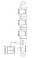
- FIG. 1 is a conceptual diagram showing an embodiment of the production method of the present invention.
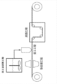
- FIG. 2 is a conceptual diagram showing another embodiment of the production method of the present invention.
- FIG. 3 is a conceptual diagram for explaining a state such as loosening of the porous substrate.
- FIG. 4 is a cross-sectional view taken along line A-A ′ of FIG.
- the notation “ ⁇ ” in a numerical range indicates a range including numerical values described before and after “ ⁇ ” as a minimum value and a maximum value, respectively.
- process is not limited to an independent process, and is included in the term if the intended action of the process is achieved even when it cannot be clearly distinguished from other processes. .
- machine direction means the long direction of the porous base material and composite membrane produced in a long shape
- width direction is orthogonal to the machine direction in the porous base material and composite membrane. It means the direction to do.
- machine direction is also referred to as “MD”
- width direction is also referred to as “TD”.
- a porous substrate containing a thermoplastic resin is heat-treated at a temperature T satisfying the following formula (hereinafter referred to as a heat treatment step), and a coating liquid containing at least a resin and a solvent Is applied to one or both sides of the porous substrate after heat treatment by adjusting the tensile stress in the machine direction of the porous substrate to a range where the elongation of the porous substrate is 2% or less.
- coating step Forming a working layer and solidifying the coating layer to obtain a composite film having a porous layer containing at least a resin on one side or both sides of the porous substrate.
- a coagulation step is included.
- Tg + 60 ° C ⁇ temperature T ⁇ Tm Tg + 60 ° C ⁇ temperature T ⁇ Tm
- Tg represents the glass transition temperature [° C.] of the thermoplastic resin contained in the porous substrate
- Tm represents the melting point [° C.] of the thermoplastic resin contained in the porous substrate.
- the manufacturing method of the composite film of this indication should just have at least a heat treatment process, a coating process, and a coagulation process, and a coagulation process makes a coating layer contact a coagulation liquid, and resin contained in a coating layer is made.
- a wet method in which a porous layer is obtained by solidification or a dry method in which a solvent contained in the coating layer is removed to solidify a resin contained in the coating layer to obtain a porous layer may be used.
- a wet method is used.
- the method for producing a composite membrane of the present disclosure preferably includes removing moisture in the composite membrane (hereinafter, drying step), and if necessary, further preparing a coating solution (hereinafter referred to as “the coating solution”). , Coating liquid preparation step), and other treatments (steps) such as washing the composite membrane with water after the coagulation step (hereinafter, water washing step).
- FIG. 1 shows an embodiment of a method for producing a composite membrane of the present invention.
- it has a coating liquid preparation process, a heat treatment process, a coating process, a coagulation process, a water washing process, and a drying process, and the coagulation process is performed by a wet method.
- a roll of a porous base material used for manufacturing a composite membrane is placed on the left side in the figure, and a roll around which the produced composite membrane is wound is placed on the right side in the figure.
- a heat treatment process, a coating process, a coagulation process, a water washing process, and a drying process are sequentially performed sequentially.
- this embodiment performs a coating liquid preparation process according to the implementation time of a coating process.
- FIG. 2 shows another embodiment of the production method of the present invention.
- it has a coating liquid preparation process, a heat treatment process, a coating process, and a coagulation process, and coagulation in the coagulation process is performed by a dry method.
- the roll of the porous base material used for manufacture of the composite membrane is placed on the left side of the drawing, and the roll of the manufactured composite membrane is placed on the right side of the drawing.
- the heat treatment process, the coating process, and the solidification process are sequentially performed sequentially.
- this embodiment performs a coating liquid preparation process according to the implementation time of a coating process.
- a heat treatment step for heat-treating the porous substrate in advance is provided before the coating step, so that the coating can be performed without applying a tension stress that causes strain to remain in the porous substrate.
- a heat treatment step for heat-treating the porous substrate in advance is provided before the coating step, so that the coating can be performed without applying a tension stress that causes strain to remain in the porous substrate.
- the slackness of the porous base material is a slack that appears in a pleat form at the end in the width direction of the porous base material when stretched between the conveying rolls.
- Fold-like deformation that occurs with an arbitrary width (sagging width P in FIG. 3) from the inside to the inner direction, and the end in the width direction hangs down in the direction of gravity as shown in FIG. 4 (hanging width Q in FIG. 4). This refers to deformation that occurs when the flat state cannot be maintained.
- the substrate may exceed the elastic limit, and after coating, the product may be deformed due to residual strain, or may be deformed due to aging or the influence of the surrounding environment. is there.
- the porous substrate before coating is preheated to alleviate the looseness of the porous substrate, surface irregularities or uneven thickness of the porous substrate, and simultaneously reduce the residual strain of the substrate ( Stress relief effect).
- the smoothness of the porous base material which is a coating object can be improved, and by extension, the composite film which has a highly uniform coating layer can be manufactured stably.
- heat treatment process In the heat treatment step, as a pretreatment step of the coating step described later, a porous substrate containing a thermoplastic resin is heat treated at a temperature T that satisfies the following formula. By heat-treating the porous substrate, the properties of the porous substrate (for example, loosening of the porous substrate, surface irregularities or uneven thickness of the porous substrate) required for stable coating are alleviated. Effect is obtained.
- Tg + 60 ° C ⁇ temperature T ⁇ Tm Tg + 60 ° C ⁇ temperature T ⁇ Tm
- Tg represents the glass transition temperature [° C.] of the thermoplastic resin contained in the porous substrate
- Tm represents the melting point [° C.] of the thermoplastic resin contained in the porous substrate.
- the heat treatment step only needs to be provided before the coating step, and may be provided in the conveyance path before coating the porous substrate fed from the roll. .
- the heat treatment is not particularly limited and may be appropriately selected as long as it is a method capable of giving the porous substrate a temperature necessary for the heat treatment over a necessary time.
- the specific method of heat treatment is not particularly limited, for example, a method of storing a porous substrate in an oven or a constant temperature room set to a necessary temperature, and subjecting the stored porous substrate to coating , A method of blowing hot air on the porous substrate, a method of heating the porous substrate with radiant heat from an infrared heater, a method of exposing to light irradiation with a heat-generating lamp (for example, a heat-generating bulb) or a laser light source, a porous hot roll or hot plate Examples thereof include a method of applying heat by contacting a porous substrate, a method of irradiating microwaves, and the like.
- the heat treatment can be performed by providing a heating means in the conveyance path before the coating process.
- the heat treatment may be performed on one of the one surface and the other surface of the porous substrate that is transported at a predetermined transport speed, or may be performed on both the one surface and the other surface.
- heat can be applied to the entire surface of the porous substrate with good uniformity by performing heat treatment from both sides of the porous substrate conveyed to the conveyance path.
- the temperature T in the above formula is the temperature of the surface of the porous substrate.
- the temperature T is calculated
- the glass transition temperature (Tg) of the thermoplastic resin is a value measured under the following conditions using a differential scanning calorimeter (DSC; Q-200, manufactured by TA Instruments). Tg was defined as an intermediate temperature (rounded off to the nearest decimal point) between the temperature decrease start point and the temperature decrease end point in the DSC curve.
- DSC differential scanning calorimeter
- Tg was defined as an intermediate temperature (rounded off to the nearest decimal point) between the temperature decrease start point and the temperature decrease end point in the DSC curve.
- ⁇ Condition> ⁇ Measurement chamber: Nitrogen atmosphere ⁇ Temperature increase rate: 5 ° C./min ⁇ Measurement start temperature: -50 °C -Measurement end temperature: 200 ° C -Sample amount: 5mg
- the melting point (Tm) is also a value measured under the same conditions using a differential scanning calorimeter (DSC) similar to the above.
- the heat treatment is performed so that the temperature T becomes “Tg + 60 ° C.” or more.
- the temperature T is less than “Tg + 60 ° C.”
- the effect of relaxing the properties of the porous substrate for example, loosening of the porous substrate, surface irregularities or uneven thickness of the porous substrate
- the temperature T at the time of heat processing is suppressed below to melting
- the temperature T during the heat treatment exceeds the melting point Tm, the porous base material is softened and it becomes difficult to maintain the shape, and on the contrary, the uniformity of the porous base material is impaired, and as a result, the coating quality is likely to deteriorate. .
- the temperature T during the heat treatment is preferably in a temperature range satisfying the following formula (1) or formula (2) for the same reason as described above.
- the time for the heat treatment is not particularly limited, and can be appropriately selected depending on the temperature of the heat treatment from the viewpoint of further improving the coatability.
- the heat treatment time is preferably, for example, 0.01 seconds to 30 seconds, and more preferably 0.1 seconds to 5 seconds.
- the tensile stress in the machine direction (MD) of the porous substrate during the heat treatment is preferably adjusted to a range in which the elongation of the porous substrate is 2% or less. That is, the tension stress applied to the porous base material during the heat treatment is preferably suppressed to a range in which the porous base material can be extended to MD by 2%.
- the tensile stress of MD is suppressed in a range where the elongation of the porous base material is 2% or less, the strain applied to the composite film does not remain. .
- a surface deposit may be generated on the surface of the connected porous substrate due to the connection. Therefore, if necessary, an apparatus for removing deposits by a weakly adhesive roll, a suction roll, or air spray is also used. Depending on the material of the porous substrate, static electricity may be charged and surrounding floating substances may adhere to it, so a static eliminator is also used. Moreover, as a method for further enhancing the effect of the heat treatment, it is preferable to use an expander roll or a spiral roll and provide equipment for extending the wrinkles (undulations) of the porous substrate.
- a coating liquid containing at least a resin and a solvent preferably a filler
- the tensile stress in the machine direction of the porous substrate is within a range where the elongation of the porous substrate is 2% or less. It adjusts and it coats on the single side
- Conventional coating means such as a Meyer bar, a die coater, a reverse roll coater, or a gravure coater may be applied for coating the coating liquid on the porous substrate.
- a coating liquid When forming a porous layer on both surfaces of a porous base material, it is preferable to apply a coating liquid to a base material simultaneously from a viewpoint of productivity.
- Coating is performed by stretching a porous substrate on MD.
- the stretching stress in the machine direction of the porous substrate is adjusted to a range in which the elongation of the porous substrate is 2% or less (102% or less of the unstretched length). That is, the coating can be performed in a state where the tension stress in the machine direction of the porous substrate is weakened.
- the surface unevenness or uneven thickness of the porous substrate Is stretched in the machine direction with a stress capable of eliminating the above-mentioned properties, and it is not necessary to maintain the stress while coating.
- the elongation of the porous substrate is measured using a tensile tester (TENSILON RTC-1225A) manufactured by A & D.
- TENSILON RTC-1225A tensile tester manufactured by A & D.
- Amount of coating can be a sum of both sides for example 10ml / m 2 ⁇ 60ml / m 2.
- the conveyance speed of the porous substrate in the coating process can be suitably performed in the range of 10 m / min or more and 100 m / min or less because it is easy to ensure production efficiency and coating stability by providing the heat treatment process.
- a ready-made coating liquid such as a stored coating liquid or a commercially available coating liquid may be used, or a coating liquid prepared according to the coating. May be used.
- a coating liquid preparation process for preparing a coating liquid containing at least a resin and a solvent can be provided as a coating liquid for coating in the above-described coating process.
- a coating liquid containing a filler, a resin and a solvent, a coating liquid containing a resin and a solvent, or an aqueous emulsion containing a resin and a solvent can be used.
- the coating liquid is prepared, for example, by dissolving a resin in a solvent, or by dissolving the resin in a solvent and further dispersing a filler.
- the details of the resin and filler used for the preparation of the coating liquid, that is, the resin and filler contained in the porous layer will be described in the section “Porous Layer” described later.
- a solvent for dissolving the resin (hereinafter also referred to as “good solvent”) used for preparing the coating liquid
- a polar amide solvent such as N-methylpyrrolidone, dimethylacetamide, dimethylformamide, dimethylformamide and the like is preferably used.
- a phase separation agent that induces phase separation in addition to a good solvent.
- the phase separation agent include water, methanol, ethanol, propyl alcohol, butyl alcohol, butanediol, ethylene glycol, propylene glycol, and tripropylene glycol.
- the phase separation agent is preferably mixed with a good solvent as long as a viscosity suitable for coating can be secured.
- the solvent used for the preparation of the coating liquid is preferably a mixed solvent containing 60% by mass or more of a good solvent and 10% to 40% by mass of a phase separation agent from the viewpoint of forming a good porous structure.
- the coating liquid contains a resin at a concentration of 3% by mass to 10% by mass and a filler at a concentration of 10% by mass to 90% by mass. preferable.
- the viscosity at 25 ° C. of the coating liquid prepared in the coating liquid preparation step is preferably in the range of 0.1 Pa ⁇ s to 5.0 Pa ⁇ s.
- the viscosity of the coating liquid is 0.1 Pa ⁇ s or more, application suitability to the porous substrate is obtained, and the effect of the composite film manufacturing method according to the present disclosure at the time of coating is further exhibited.
- a coating liquid can be supplied more stably as the viscosity of a coating liquid is 5.0 Pa.s or less.
- the viscosity (25 degreeC) of a coating liquid 1.0 Pa.s or more is more preferable, More preferably, it is 2.0 Pa.s or more.
- the viscosity (25 ° C.) of the coating solution is more preferably 4.0 Pa ⁇ s or less, and still more preferably 3.0 Pa ⁇ s or less.
- the viscosity can be controlled by the composition ratio of the solvent, the resin and the filler.
- the viscosity is a value measured using a rotary viscometer (B-type viscometer manufactured by Eiko Seiki Co., Ltd.) in a state where the temperature of the coating liquid is adjusted to 25 ° C.
- a composite film having a porous layer containing at least a resin on one side or both sides of the porous substrate is obtained by solidifying the coating layer formed in the coating step.
- the coagulation step is a wet method in which the coating layer is brought into contact with the coagulation liquid to solidify the resin contained in the coating layer to obtain a porous layer, or the solvent contained in the coating layer is removed and included in the coating layer.
- Any of the dry methods for solidifying the resin to obtain a porous layer may be used.
- the dry method is advantageous in terms of the process because it does not require contact with the coagulation liquid and washing with water necessary for the wet method, but the porous layer tends to be denser than the wet method. Therefore, in the present disclosure, an embodiment by a wet method is preferable from the viewpoint of obtaining a good porous structure.
- a porous substrate having a coating layer in a coagulation liquid, and specifically, it is preferable to pass through a tank (coagulation tank) containing the coagulation liquid.
- the coagulation liquid used in the wet method is generally prepared from the good solvent and the phase separation agent used in the preparation of the coating liquid and water. It is preferable in production that the mixing ratio of the good solvent and the phase separation agent is adjusted to the mixing ratio of the mixed solvent used for preparing the coating liquid.
- the concentration of water is suitably in the range of 40% by mass to 80% by mass with respect to the total amount of the coagulating liquid in terms of the formation and productivity of the porous structure.
- the temperature of the coagulation liquid can be, for example, 20 ° C. to 50 ° C.
- the method for removing the solvent from the composite membrane is not particularly limited, and examples thereof include a method in which the composite membrane is brought into contact with a heat generating member, and a method in which the composite membrane is transported into a chamber adjusted in temperature and humidity. It is done.
- the heat temperature is, for example, 50 ° C. to 80 ° C.
- the method for manufacturing the composite film of the present disclosure preferably includes a water washing process for washing the composite film after the coagulation process.
- the solvent the solvent used for the coating liquid and the solvent used for the coagulation liquid contained in the composite film is removed.
- the water washing step may be performed by transporting the composite membrane through a water bath.
- the temperature of water for washing is, for example, 0 ° C. to 70 ° C.
- the manufacturing method of the composite membrane of this indication has the drying process which removes water from a composite membrane after the said water washing process.
- the drying method is not particularly limited, and examples thereof include a method in which the composite film is brought into contact with the heat generating member, and a method in which the composite film is conveyed into a chamber in which temperature and humidity are adjusted.
- the heat temperature is, for example, 50 ° C. to 80 ° C.
- the porous substrate means a substrate having pores or voids inside.
- a substrate include a microporous film; a porous sheet made of a fibrous material such as a nonwoven fabric and paper; a composite porous material in which one or more other porous layers are laminated on the microporous film or the porous sheet. Quality sheet; and the like.
- a microporous membrane is preferable from the viewpoint of thinning and strength of the composite membrane.
- a microporous membrane means a membrane that has a large number of micropores inside and a structure in which these micropores are connected, and allows gas or liquid to pass from one surface to the other. To do.
- the material constituting the porous substrate is preferably an electrically insulating material, and may be either an organic material or an inorganic material.
- the material constituting the porous substrate is preferably a thermoplastic resin from the viewpoint of imparting a shutdown function to the porous substrate.
- the shutdown function blocks the movement of ions by blocking the pores of the porous base material by dissolving the constituent materials. A function that prevents thermal runaway.
- thermoplastic resin a thermoplastic resin having a melting point of less than 200 ° C. is suitable, and polyolefin is particularly preferable.
- the polyolefin microporous membrane preferably contains one or both of polyethylene and propylene from the viewpoint of exhibiting a shutdown function.
- the polyolefin microporous membrane preferably contains polyethylene from the same viewpoint as described above, and more preferably a polyethylene microporous membrane having a polyethylene content of 95% by mass or more.
- the polyolefin microporous membrane is preferably a polyolefin microporous membrane containing polyethylene and polypropylene from the viewpoint of heat resistance that does not easily break when exposed to high temperatures.
- a polyolefin microporous membrane include a microporous membrane in which polyethylene and polypropylene are mixed in one layer.
- a polyolefin microporous membrane containing 95% by mass or more of polyethylene and 5% by mass or less of polypropylene is preferable from the viewpoint of achieving both a shutdown function and heat resistance.
- the polyolefin microporous membrane has a laminated structure of two or more layers, at least one layer contains polyethylene, and at least one layer has a laminated structure containing polypropylene.
- a porous membrane is preferred.
- the polyolefin contained in the polyolefin microporous membrane preferably has a weight average molecular weight of 100,000 to 5,000,000. When the weight average molecular weight is 100,000 or more, good mechanical properties can be secured. When the weight average molecular weight is 5 million or less, the shutdown characteristics are good and the film formation is easy.
- the polyolefin microporous membrane can be produced, for example, by the following method. That is, The first method is a method in which a molten polyolefin resin is extruded from a T-die to form a sheet, which is crystallized and then stretched, and further heat-treated to form a microporous film. In the second method, a polyolefin resin melted with a plasticizer such as liquid paraffin is extruded from a T-die, cooled and formed into a sheet, and after stretching, the plasticizer is extracted and heat-treated to form a microporous material. This is a method of forming a film.
- a plasticizer such as liquid paraffin
- porous sheets made of fibrous materials include polyesters such as polyethylene terephthalate; polyolefins such as polyethylene and polypropylene; heat-resistant resins such as aromatic polyamide, polyimide, polyethersulfone, polysulfone, polyetherketone, and polyetherimide; cellulose A porous sheet such as a nonwoven fabric or paper made of a fibrous material such as;
- the heat resistant resin refers to a resin having a melting point of 200 ° C. or higher, or a resin having no melting point and a decomposition temperature of 200 ° C. or higher.
- the composite porous sheet a structure in which a functional layer is laminated on a porous sheet made of a microporous film or a fibrous material can be adopted. Such a composite porous sheet is preferable in that a further function can be added by the functional layer.
- a porous layer made of a heat resistant resin, or a porous layer made of a heat resistant resin and an inorganic filler can be adopted.
- the heat resistant resin include one or more heat resistant resins selected from aromatic polyamide, polyimide, polyethersulfone, polysulfone, polyetherketone and polyetherimide.
- a metal oxide such as alumina; a metal hydroxide such as magnesium hydroxide; and the like can be preferably used.
- a composite method a method of applying a functional layer to a microporous membrane or a porous sheet, a method of bonding the microporous membrane or porous sheet and the functional layer with an adhesive, a microporous membrane or a porous sheet, Examples include a method of thermocompression bonding with the functional layer.
- the glass transition temperature of the thermoplastic resin (that is, the glass transition temperature before heat treatment) is preferably in the range of 30 ° C. or less, more preferably in the range of 0 ° C. or less, and still more preferably in the range of ⁇ 10 ° C. or less. When the glass transition temperature is 30 ° C. or lower, heat treatment can be easily performed.
- the glass transition temperature is preferably in the range of ⁇ 50 ° C. or higher, more preferably in the range of ⁇ 30 ° C. or higher, from the viewpoint of productivity.
- the porous substrate is preferably a long material having a width of 0.1 m to 3.0 m from the viewpoint of suitability for the production method of the present disclosure.
- the thickness of the porous substrate is preferably in the range of 5 ⁇ m to 50 ⁇ m, more preferably in the range of 5 ⁇ m to 30 ⁇ m, and more preferably in the range of 5 ⁇ m from the viewpoint of mechanical strength, that is, the average value (that is, the average value of the thickness before heat treatment). A range of ⁇ 20 ⁇ m is more preferable.
- the thickness of the porous substrate is obtained as an average value of measured values by measuring 20 arbitrary points within 10 cm ⁇ 30 cm with a contact-type thickness meter (LITEMATIC manufactured by Mitutoyo Corporation).
- the measurement terminal is a column having a diameter of 5 mm and is adjusted so that a load of 7 g is applied during the measurement.
- the standard deviation of the thickness of the porous substrate (that is, the standard deviation of the thickness before heat treatment) is preferably in the range of 0.35 ⁇ m to 30 ⁇ m, more preferably in the range of 0.40 ⁇ m to 30 ⁇ m, and The range of 45 ⁇ m to 20 ⁇ m is more preferable, the range of 0.45 ⁇ m to 5 ⁇ m is more preferable, and the range of 0.45 ⁇ m to 1 ⁇ m is still more preferable.
- the standard deviation of the thickness is calculated from the thickness measured as described above.
- the Gurley value (JIS P8117 (2009)) of the porous substrate is preferably 50 seconds / 100 cc to 800 seconds / 100 cc from the viewpoint of mechanical strength and material permeability.
- the porosity of the porous substrate is preferably 20% to 60% from the viewpoint of mechanical strength, handling properties, and material permeability.
- the average pore diameter of the porous substrate is preferably 20 nm to 100 nm from the viewpoint of substance permeability.
- the average pore diameter is a value measured using a palm porometer according to ASTM E1294-89.
- the porous layer is a layer having a large number of micropores inside and a structure in which these micropores are connected so that gas or liquid can pass from one surface to the other.
- the porous layer is preferably an adhesive porous layer capable of adhering to the electrode when the composite membrane is applied to a battery separator.
- the adhesive porous layer may be provided only on one surface of the porous substrate, and more preferably on both surfaces of the porous substrate.
- the porous layer is formed by applying a coating liquid containing a filler, a resin and a solvent, a coating liquid containing a resin and a solvent, or an aqueous emulsion containing a resin and a solvent. Therefore, the porous layer contains a resin and a filler, or a resin.
- porous layer and components such as a resin contained in the coating liquid used for forming the porous layer will be described.
- the type of the resin contained in the porous layer is not limited. As resin contained in a porous layer, what has a function which connects a filler (what is called binder resin) is preferable. When the composite membrane is used as a battery separator, the resin contained in the porous layer is stable to an electrolytic solution, electrochemically stable, has a function of connecting inorganic particles, and can be bonded to an electrode. Those are preferred.
- the resin contained in the porous layer is preferably a hydrophobic resin from the viewpoint of production compatibility when the composite membrane is produced by a wet method.
- the porous layer may contain one kind of resin or two or more kinds.
- the resin examples include polyvinylidene fluoride, polyvinylidene fluoride copolymer, styrene-butadiene copolymer, homopolymers or copolymers of vinyl nitriles such as acrylonitrile and methacrylonitrile, polyethylene oxide and polypropylene oxide.
- Polyethers are preferred.
- polyvinylidene fluoride and a polyvinylidene fluoride copolymer (these are also collectively referred to as a polyvinylidene fluoride resin) are particularly preferable.
- polyvinylidene fluoride resin examples include homopolymers of vinylidene fluoride (that is, polyvinylidene fluoride), copolymers of vinylidene fluoride and other copolymerizable monomers (that is, polyvinylidene fluoride copolymer), and these And the like.
- monomer copolymerizable with vinylidene fluoride examples include tetrafluoroethylene, hexafluoropropylene, trifluoroethylene, trichloroethylene, vinyl fluoride, and the like, and one kind or two or more kinds can be used.
- the polyvinylidene fluoride resin is obtained by emulsion polymerization or suspension polymerization.
- the resin contained in the porous layer is preferably a heat-resistant resin (a resin having a melting point of 200 ° C. or higher, or a resin having no melting point and a decomposition temperature of 200 ° C. or higher) from the viewpoint of heat resistance.
- the heat resistant resin include polyamide (nylon), wholly aromatic polyamide (aramid), polyimide, polyamideimide, polysulfone, polyketone, polyetherketone, polyethersulfone, polyetherimide, cellulose, and a mixture thereof. It is done.
- wholly aromatic polyamides are preferable from the viewpoints of easy formation of a porous structure, binding properties with inorganic particles, oxidation resistance, and the like.
- meta-type wholly aromatic polyamides are preferable from the viewpoint of easy molding, and polymetaphenylene isophthalamide is particularly preferable.
- a particulate resin or a water-soluble resin can be appropriately used as the resin in the method for manufacturing a composite film according to the embodiment of the present invention.
- the particulate resin include resin particles containing a resin such as polyvinylidene fluoride resin, fluorine rubber, and styrene-butadiene rubber.
- the resin particles can be used by preparing a coating liquid by dispersing the resin particles in a dispersion medium such as water.
- the water-soluble resin include cellulosic resins and polyvinyl alcohol. In this case, water can be used as a solvent.
- the particulate resin and the water-soluble resin are suitable when the coagulation step is performed by a dry method.
- the filler contained in the porous layer is not limited in type, and may be either an inorganic filler or an organic filler.
- the filler is preferably particles in which the primary particles have a volume average particle diameter of 0.01 ⁇ m to 10 ⁇ m. When the volume average particle diameter of the filler is within the above range, the balance of characteristics is improved so as to increase the slipperiness during production, increase the yield, and satisfy the adhesiveness with the electrode and the retention of the electrolytic solution. Can do.
- the volume average particle diameter of the filler is more preferably 0.1 ⁇ m to 10 ⁇ m, and further preferably 0.1 ⁇ m to 3.0 ⁇ m.
- the volume average particle diameter of the filler is a value measured using a laser diffraction particle size distribution measuring apparatus.
- inorganic particles are preferable from the viewpoint of porosity and heat resistance.
- the inorganic particles contained in the porous layer are preferably those that are stable to the electrolytic solution and electrochemically stable.
- the porous layer may contain one kind of inorganic particles or two or more kinds.
- the inorganic particles include metal hydroxides such as aluminum hydroxide, magnesium hydroxide, calcium hydroxide, chromium hydroxide, zirconium hydroxide, cerium hydroxide, nickel hydroxide, boron hydroxide; silica, alumina, zirconia And metal oxides such as magnesium oxide; carbonates such as calcium carbonate and magnesium carbonate; sulfates such as barium sulfate and calcium sulfate; clay minerals such as calcium silicate and talc; Among these, metal hydroxides and metal oxides are preferable from the viewpoint of imparting flame retardancy and neutralizing effect.
- the inorganic particles may be surface-modified with a silane coupling agent or the like.
- the particle shape of the inorganic particles is arbitrary, and may be spherical, elliptical, plate-like, rod-like, or indefinite.
- the inorganic particles preferably have a primary particle volume average particle size of 0.01 ⁇ m to 10 ⁇ m, preferably 0.1 ⁇ m, from the viewpoint of moldability of the porous layer, material permeability of the composite membrane, and slipperiness of the composite membrane. More preferably, it is ⁇ 10 ⁇ m, and further preferably 0.1 ⁇ m to 3.0 ⁇ m.
- the proportion of inorganic particles in the total amount of resin and inorganic particles is, for example, 30% to 90% by volume.
- the porous layer may contain an organic filler as a filler.
- the organic filler include cross-linked poly (meth) acrylic acid, cross-linked poly (meth) acrylic acid ester, cross-linked polysilicon, cross-linked polystyrene, cross-linked polydivinylbenzene, styrene-divinylbenzene copolymer cross-linked product, polyimide, and melamine resin.
- particles made of a crosslinked polymer such as a phenol resin and a benzoguanamine-formaldehyde condensate; particles made of a heat-resistant resin such as polysulfone, polyacrylonitrile, aramid, polyacetal, and thermoplastic polyimide.
- the thickness of the porous layer is preferably 0.5 ⁇ m to 5 ⁇ m on one side of the porous substrate from the viewpoint of mechanical strength.
- the porosity of the porous layer is preferably 30% to 80% from the viewpoints of mechanical strength, handling properties, and material permeability.
- the pore diameter of the porous layer is preferably 20 nm to 100 nm from the viewpoint of substance permeability.
- the average pore diameter is a value measured using a palm porometer according to ASTM E1294-89.
- the thickness of the composite film is, for example, 5 ⁇ m to 100 ⁇ m, and can be set to, for example, 5 ⁇ m to 50 ⁇ m for battery separator applications.
- the porosity of the composite membrane is preferably 30% to 60% from the viewpoints of mechanical strength, handling properties, and material permeability.
- the method for manufacturing a composite film according to an embodiment of the present invention is not limited to the following examples as long as the gist thereof is not exceeded.
- any 20 points within 10 cm ⁇ 30 cm were measured with a contact-type thickness meter (manufactured by Mitutoyo Corporation, LITEMATIC), and the average value and standard deviation of the thickness were calculated from the measured values.
- the measurement terminal was a column having a diameter of 5 mm and was adjusted so that a load of 7 g was applied during the measurement.
- the slack width from both ends in the width direction and the difference in height from the film surface to the end that hangs down in the gravitational direction at the end in the width direction were measured by the following methods. .
- (1) Sag width As shown in FIG. 3, a polyethylene microporous membrane is placed at a constant tension (at the time of coating in each of the examples or comparative examples) between two support rolls fixedly arranged 2 m apart in the conveyance path. The distance (slack width P) from the end in the width direction of the stretched and slackened region was measured in a state where the substrate was stretched by giving (base material elongation).
- thermoplastic resin The glass transition temperature (Tg) of the thermoplastic resin contained in the porous substrate was measured using a differential scanning calorimeter (DSC; Q-200, manufactured by TA Instruments) under the following conditions. Tg was calculated by rounding off the intermediate temperature between the temperature decrease start point and the temperature decrease end point in the DSC curve.
- DSC differential scanning calorimeter
- thermoplastic resin-Tm of thermoplastic resin-
- DSC differential scanning calorimeter
- the porous substrate was formed using polyethylene (thermoplastic resin; glass transition temperature (Tg): ⁇ 20 ° C., melting point (Tm): 135 ° C.), with a thickness of 16 ⁇ m (average value) and a width of 450 mm.
- a long polyethylene microporous membrane (Gurley value: 200 seconds / 100 ml, porosity: 50%) was prepared.
- the polyethylene microporous film fed from the unwinding roll and transported through the transport path has a slack width P of 95 mm from both ends in the width direction, and the film surface at the end in the width direction.
- the height difference (hanging width Q) from the edge to the end hanging down in the direction of gravity was 17 mm.
- the slack width and the sagging width were measured by the above methods.
- This polyethylene microporous membrane was subjected to heat treatment by contacting it with a hot plate at 60 ° C. for 1.2 seconds.
- the heat-treated polyethylene microporous membrane is conveyed to the position where the coating device is placed while gradually applying tension, and when the tension applied to the polyethylene microporous membrane reaches 9 N (Newton), the slack at the end in the width direction Disappeared.
- the elongation of the polyethylene microporous membrane at this time was 0.1%.
- the coating liquid was applied to one side of the polyethylene microporous film with a die coater, and the thickness was 3 ⁇ m. A coating layer was formed.
- the conveyance speed of the polyethylene microporous film in the coating process was 10 m / min.
- the composite membrane was transported to a water tank and washed with water through a water bath adjusted to a water temperature of 30 ° C. and contained in the water tank. Subsequently, the washed composite membrane was passed through a drying apparatus and dried.
- Example 1 Example 2 to 7, Example 9
- Example 9 Example 9
- a polypropylene microporous membrane having a thickness of 18 ⁇ m (average value) and a width of 450 mm formed using polypropylene (thermoplastic resin) (Gurley value: 200 seconds / 100 ml, empty) Porosity: 50%) was used.
- the same evaluation as in Example 1 was performed. The evaluation results are shown in Table 1.
- Example 1 (Comparative Examples 1 to 6) In Example 1, except that the conditions of the heat treatment step and the substrate elongation at the time of coating were changed as shown in Table 1, each step was carried out continuously in the same manner as in Example 1, and polyethylene was obtained. A composite membrane having a porous layer on one side of the microporous membrane was produced. The same evaluation as in Example 1 was performed. The evaluation results are shown in Table 1.
- a highly uniform coating layer can be stably formed by applying a predetermined heat treatment to the porous substrate in advance before applying the coating liquid to the porous substrate. And the internal stress of the obtained composite film can be kept low. Both polyethylene and polypropylene used as the porous substrate showed good results. On the other hand, in Comparative Examples 1 to 4 in which the predetermined heat treatment was not performed, the formed coating layer was not uniform, and a coating failure sometimes occurred in a part of the porous substrate. Moreover, in the comparative example 3 which gave the strong stress to the porous base material at the time of coating, the internal stress of the obtained composite film was high, and the desired shape could not be maintained.
- Comparative Example 6 even when heat treatment was performed, the internal stress of the composite film increased, and the desired shape could not be maintained.
- Comparative Example 5 in which the heat treatment was performed at a heat treatment temperature exceeding the melting point of the porous substrate, the substrate itself was melted, and conveyance and coating were difficult.
Landscapes
- Chemical & Material Sciences (AREA)
- Chemical Kinetics & Catalysis (AREA)
- Engineering & Computer Science (AREA)
- General Chemical & Material Sciences (AREA)
- Electrochemistry (AREA)
- Medicinal Chemistry (AREA)
- Health & Medical Sciences (AREA)
- Organic Chemistry (AREA)
- Polymers & Plastics (AREA)
- Manufacturing & Machinery (AREA)
- Mechanical Engineering (AREA)
- Power Engineering (AREA)
- Materials Engineering (AREA)
- Inorganic Chemistry (AREA)
- Thermal Sciences (AREA)
- Physics & Mathematics (AREA)
- Life Sciences & Earth Sciences (AREA)
- Wood Science & Technology (AREA)
- Microelectronics & Electronic Packaging (AREA)
- Cell Separators (AREA)
- Manufacture Of Porous Articles, And Recovery And Treatment Of Waste Products (AREA)
- Application Of Or Painting With Fluid Materials (AREA)
- Laminated Bodies (AREA)
- Separation Using Semi-Permeable Membranes (AREA)
Abstract
Description
さらに、塗工後の基材をあらかじめ定められたコアに巻回してロールとした場合、ロールの最表面に顕著な凹凸ができたり、ロールの端部に変形又は不揃い等が生じる要因となる。また、二次加工後の製品にも同様の外観不良が生じることになる。
<1> 熱可塑性樹脂を含む多孔質基材を、下記式を満たす温度Tで熱処理すること(熱処理工程)と、前記多孔質基材における機械方向の張架応力を多孔質基材の伸度が2%以下となる範囲に調整し、少なくとも樹脂及び溶媒を含む塗工液を、熱処理後の前記多孔質基材の片面又は両面に塗工し、塗工層を形成すること(塗工工程)と、前記塗工層を凝固させて、前記多孔質基材の片面又は両面に、少なくとも樹脂を含む多孔質層を有する複合膜を得ること(凝固工程)と、を有する複合膜の製造方法である。
Tg:多孔質基材に含まれる熱可塑性樹脂のガラス転移温度[℃]
Tm:多孔質基材に含まれる熱可塑性樹脂の融点[℃]
<3> 前記熱処理が施される前の前記多孔質基材の厚みの標準偏差が0.40μm~30μmである前記<1>又は前記<2>に記載の複合膜の製造方法である。
<4> 前記熱処理が施される前の前記多孔質基材のガラス転移温度が30℃以下である前記<1>~前記<3>のいずれか1つに記載の複合膜の製造方法である。
<5> 複合膜を得る前記凝固工程は、塗工層を凝固液に接触させて樹脂を凝固させ、多孔質基材の片面又は両面に、少なくとも樹脂を含む多孔質層を有する複合膜を得ること(工程)である前記<1>~前記<4>のいずれか1つに記載の複合膜の製造方法である。
<6> 前記塗工液は、更に、フィラーを含み、前記凝固工程で塗工層を凝固させて得られる多孔質層は、更に、フィラーを含む前記<1>~前記<5>のいずれか1つに記載の複合膜の製造方法である。
本開示の複合膜の製造方法は、熱可塑性樹脂を含む多孔質基材を、以下に示す式を満たす温度Tで熱処理すること(以下、熱処理工程)と、少なくとも樹脂及び溶媒を含む塗工液を、多孔質基材における機械方向の張架応力を多孔質基材の伸度が2%以下となる範囲に調整して、熱処理後の多孔質基材の片面又は両面に塗工し、塗工層を形成すること(以下、塗工工程)と、前記塗工層を凝固させて、前記多孔質基材の片面又は両面に、少なくとも樹脂を含む多孔質層を有する複合膜を得ること(以下、凝固工程)と、を少なくとも有している。
式中、Tgは、多孔質基材に含まれる熱可塑性樹脂のガラス転移温度[℃]を表し、Tmは、多孔質基材に含まれる熱可塑性樹脂の融点[℃]を表す。
しかしながら、多孔質基材に必要以上の張力が加えられると、基材が弾性限界を超えて、塗工後に、残留する歪みによって製品が変形したり、経時又は周囲環境の影響で変形することがある。
本開示においては、塗工前の多孔質基材をあらかじめ熱処理することにより、多孔質基材の弛み、多孔質基材の表面凹凸又は厚みムラを緩和し、同時に基材の残留歪を低減(ストレスレリーフ効果)する。これにより、被塗物である多孔質基材の平滑性を向上し、ひいては均一性の高い塗工層を有する複合膜を安定的に製造することができる。
[熱処理工程]
熱処理工程では、後述の塗工工程の前処理工程として、熱可塑性樹脂を含む多孔質基材を、以下に示す式を満たす温度Tで熱処理する。多孔質基材を熱処理することで、塗工を安定的に行うのに求められる多孔質基材の性状(例えば、多孔質基材の弛み、多孔質基材の表面凹凸又は厚みムラ)を緩和する効果が得られる。
Tg+60℃ ≦ 温度T ≦ Tm
式中、Tgは、多孔質基材に含まれる熱可塑性樹脂のガラス転移温度[℃]を表し、Tmは、多孔質基材に含まれる熱可塑性樹脂の融点[℃]を表す。
熱処理の具体的な手法としては、特に制限はなく、例えば、必要な温度に設定したオーブン又は恒温室に入れて多孔質基材を保管し、保管された多孔質基材を塗工に供する方法、熱風を多孔質基材に吹き付ける方法、赤外線ヒータによる輻射熱で多孔質基材を加熱する方法、発熱ランプ(例えば発熱電球)又はレーザ光源による光照射下に曝す方法、熱ロール又は熱板を多孔質基材に接触させて熱を付与する方法、マイクロ波を照射する方法、等が挙げられる。
<条件>
・測定室:窒素雰囲気
・昇温速度:5℃/min
・測定開始温度:-50℃
・測定終了温度:200℃
・試料量:5mg
また、融点(Tm)も、上記と同様の示差走査熱量計(DSC)を用い、同条件にて測定される値である。
熱処理時の温度Tは、上記と同様の理由から、下記の式(1)又は式(2)を満たす温度範囲にあることが好ましい。
Tg+60℃ ≦ 温度T ≦ Tm-20℃ ・・・(1)
Tg+80℃ ≦ 温度T ≦ Tm-40℃ ・・・(2)
MDの張架応力としては、具体的には、0.1N/cm以上3N/cm以下が好ましく、0.5N/cm以上2N/cm以下がより好ましい。
多孔質基材の張架応力は、温度20℃の雰囲気下、引張試験機を用いて、多孔質基材に対して引張速度100mm/分にて引張試験を行うことで計測される。
なお、熱処理の事前工程として、熱処理工程に長尺状の多孔質基材を連続的に繰り出すために、複数本以上の長尺状の多孔質基材を、接着剤、両面テープ、熱融着などによって多孔質基材同士を接続しながら繰り出してもよい。この場合、接続された多孔質基材表面には、接続により表面付着物を生じることがある。そのため、必要により、弱粘着性ロール、サクションロール、空気噴霧による、付着物を除去する装置も用いられる。また、多孔質基材の材質によっては、静電気を帯電し、周囲の浮遊物が付着する場合もあるため、静電気除去装置も用いられる。また、熱処理の効果をより高める方法として、エキスパンダーロール、螺旋状ロールを用い、多孔質基材の皺(波打ち)を伸ばすための設備を備えることが好ましい。
塗工工程では、少なくとも樹脂と溶媒と(好ましくはフィラーと)を含む塗工液を、多孔質基材における機械方向の張架応力を多孔質基材の伸度が2%以下となる範囲に調整して、熱処理後の多孔質基材の片面または両面に塗工し、塗工層を形成する。塗工液の塗工が、前記熱処理工程を経ることによって、弛み、表面凹凸、厚みムラが緩和され、同時に残留歪が低減された多孔質基材に対して行われるので、均一性の高い塗工層が形成される。
塗工工程における多孔質基材の搬送速度は、前記熱処理工程を設けることで、生産効率と塗工安定性を確保しやすいため、10m/分以上100m/分以下の範囲で好適に行える。
本開示の複合膜の製造方法では、保管された塗工液又は上市されている市販の塗工液などの既製の塗工液を用いてもよいし、塗工に合わせて調製した塗工液を用いてもよい。後者の場合、既述の塗工工程で塗工するための塗工液として、少なくとも樹脂及び溶媒を含む塗工液を調製する塗工液調製工程を設けることができる。塗工液には、フィラー、樹脂及び溶媒を含む塗工液、樹脂及び溶媒を含む塗工液、又は、樹脂及び溶剤を含む水系エマルションを用いることができる。
なお、塗工液の調製に用いる樹脂及びフィラー、すなわち多孔質層に含有される樹脂及びフィラーの詳細については、後述の「多孔質層」の項において説明する。
良好な多孔構造を有する多孔質層を形成する観点で、良溶媒に加えて相分離を誘発させる相分離剤を混合させることが好ましい。相分離剤としては、水、メタノール、エタノール、プロピルアルコール、ブチルアルコール、ブタンジオール、エチレングリコール、プロピレングリコール、トリプロピレングリコール等が挙げられる。相分離剤は、塗工に適切な粘度が確保できる範囲で良溶媒と混合することが好ましい。
塗工液の粘度(25℃)は、1.0Pa・s以上がより好ましく、更に好ましくは2.0Pa・s以上である。また、塗工液の粘度(25℃)は、4.0Pa・s以下がより好ましく、更に好ましくは3.0Pa・s以下である。
粘度は、溶媒、樹脂及びフィラーの組成比によって制御可能である。
また、粘度は、塗工液を25℃に温調した状態で回転型粘度計(英弘精機社製のB型粘度計)を用いて測定される値である。
凝固工程では、塗工工程で形成された塗工層を凝固させることで、多孔質基材の片面又は両面に、少なくとも樹脂を含む多孔質層を有する複合膜が得られる。
本開示の複合膜の製造方法は、凝固工程として湿式法を採用した場合、凝固工程後に複合膜を水洗する水洗工程を有することが好ましい。水洗工程では、複合膜に含まれている溶媒(塗工液に用いられる溶媒及び凝固液に用いられる溶媒)を除去する。
本開示の複合膜の製造方法は、前記水洗工程後に複合膜から水を除去する乾燥工程を有することが好ましい。乾燥方法には、特に制限はなく、例えば、複合膜を発熱部材に接触させる方法、温度及び湿度を調整したチャンバー内に複合膜を搬送する方法、等が挙げられる。
複合膜に熱を付与する場合、熱の温度としては、例えば50℃~80℃である。
[多孔質基材]
多孔質基材とは、内部に空孔ないし空隙を有する基材を意味する。このような基材としては、微多孔膜;不織布、紙等の繊維状物からなる多孔性シート;これら微多孔膜や多孔性シートに他の多孔性の層を1層以上積層させた複合多孔質シート;などが挙げられる。
第1の方法は、溶融したポリオレフィン樹脂をT-ダイから押し出してシート化し、これを結晶化処理した後に延伸し、さらに熱処理をして微多孔膜とする方法である。また、第2の方法は、流動パラフィンなどの可塑剤とともに溶融したポリオレフィン樹脂をT-ダイから押し出し、これを冷却してシート化し、延伸した後、可塑剤を抽出して熱処理することで微多孔膜とする方法である。
耐熱性樹脂とは、融点が200℃以上の樹脂、又は融点を有さず分解温度が200℃以上の樹脂を指す。
多孔質基材の厚みは、接触式の厚み計(ミツトヨ社製のLITEMATIC)にて、10cm×30cm内の任意の20点を測定し、測定された値の平均値として求められる。なお、測定端子は、直径5mmの円柱状のものを用い、測定中に7gの荷重が印加されるように調整される。
厚みの標準偏差は、上記のように測定される厚みから算出される。
多孔質層は、内部に多数の微細孔を有し、これら微細孔が連結された構造となっており、一方の面から他方の面へと気体あるいは液体が通過可能となった層である。
多孔質層に含まれる樹脂は、種類に制限はない。多孔質層に含まれる樹脂としては、フィラーを連結する機能を有するもの(いわゆるバインダ樹脂)が好ましい。多孔質層に含まれる樹脂は、複合膜が電池セパレータとして利用される場合、電解液に安定であり、電気化学的に安定であり、無機粒子を連結する機能を有し、電極と接着し得るものが好ましい。多孔質層に含まれる樹脂は、複合膜を湿式法で製造する場合は製造適合性の観点から、疎水性樹脂が好ましい。
多孔質層は、樹脂を1種含んでもよく2種以上含んでもよい。
フッ化ビニリデンと共重合可能なモノマーとしては、例えば、テトラフロロエチレン、ヘキサフロロプロピレン、トリフロロエチレン、トリクロロエチレン、フッ化ビニル等が挙げられ、1種類又は2種類以上を用いることができる。
ポリフッ化ビニリデン系樹脂は、乳化重合または懸濁重合により得られる。
耐熱性樹脂としては、例えば、ポリアミド(ナイロン)、全芳香族ポリアミド(アラミド)、ポリイミド、ポリアミドイミド、ポリスルホン、ポリケトン、ポリエーテルケトン、ポリエーテルスルホン、ポリエーテルイミド、セルロース、及びこれらの混合物が挙げられる。中でも、多孔構造の形成のしやすさ、無機粒子との結着性、耐酸化性などの観点で、全芳香族ポリアミドが好ましい。全芳香族ポリアミドの中でも、成形が容易という観点で、メタ型全芳香族ポリアミドが好ましく、特にポリメタフェニレンイソフタルアミドが好適である。
多孔質層に含まれるフィラーは、種類に制限はなく、無機フィラー及び有機フィラーのいずれでもよい。フィラーは、一次粒子の体積平均粒径が0.01μm~10μmである粒子が好ましい。フィラーの体積平均粒径が上記範囲内であると、製造時の滑り性を高めて歩留まりを高め、かつ、電極との接着性及び電解液の保持性を満足するような特性のバランスを図ることができる。フィラーの体積平均粒径は、0.1μm~10μmであることがより好ましく、0.1μm~3.0μmであることが更に好ましい。
フィラーの体積平均粒径は、レーザー回折式粒度分布測定装置を用いて測定される値である。
多孔質層の厚さは、機械強度の観点から、多孔質基材の片面において0.5μm~5μmが好ましい。
本開示の複合膜の製造方法では、熱可塑性樹脂を含む多孔質基材上に多孔質層を有する複合膜が作製される。
以下に示す実施例及び比較例で作製したセパレータ及びリチウムイオン二次電池について、以下の測定、評価を行なった。測定及び評価の結果は、下記の表1に示す。
多孔質基材に対して、接触式の厚み計(ミツトヨ社製、LITEMATIC)にて10cm×30cm内の任意の20点を測定し、測定値から厚みの平均値及び標準偏差を算出した。なお、測定端子は、直径5mmの円柱状のものを用い、測定中に7gの荷重が印加されるように調整した。
塗工液の25℃での粘度(Pa・s)を、回転型粘度計(英弘精機社製B型粘度計)を用いて測定した。
多孔質基材の撓みとして、幅方向両端からの弛み幅と、幅方向端部において膜面から重力方向に垂れ下がった端部までの高さの差(垂れ幅)と、を下記方法で測定した。
(1)弛み幅
図3に示すように、搬送路に2m離して固定配置された2つの支持ロール間に、ポリエチレン微多孔膜を、一定張力(各々の実施例又は比較例における塗工時の基材伸度)を与えて引っ張った状態で張り、弛んでいる領域の幅方向端部からの距離(弛み幅P)を測定した。
(2)垂れ幅
図3~図4に示すように、搬送路に2m離して固定配置された2つの支持ロール間に、ポリエチレン微多孔膜を、一定張力(各々の実施例又は比較例における塗工時の基材伸度)を与えて引っ張った状態で張り、所定の高さから膜面(弛みのない領域)までの距離と、所定の高さから重力方向に垂れ下がった端部までの距離と、の差(垂れ幅Q)を算出した。
多孔質基材に含まれる熱可塑性樹脂のガラス転移温度(Tg)を、示差走査熱量計(DSC;Q-200、TAインスルメンツ社製)を用いて下記の条件にて測定した。Tgは、DSC曲線における温度の下降開始点と下降終了点との中間温度を小数点以下四捨五入して求めた。
<条件>
・測定室:窒素雰囲気
・昇温速度:5℃/min
・測定開始温度:-50℃
・測定終了温度:200℃
・試料量:5mg
多孔質基材に含まれる熱可塑性樹脂の融点(Tm)を、示差走査熱量計(DSC;Q-200、TAインスルメンツ社製)を用いて上記と同条件にて測定した。
-塗工液調製工程-
ポリメタフェニレンイソフタルアミドを、ジメチルアセトアミドとトリプロピレングリコールとの混合溶媒に溶解し、得られた溶液に水酸化アルミニウム(無機フィラー;一次粒子の体積平均粒径:0.8μm)を分散させることにより、塗工液を調製した。
塗工液の組成は、質量比で、水酸化アルミニウム:ポリメタフェニレンイソフタルアミド:ジメチルアセトアミド:トリプロピレングリコール=16:4:40:40とした。
多孔質基材として、ポリエチレン(熱可塑性樹脂;ガラス転移温度(Tg):-20℃、融点(Tm):135℃)を用いて成膜された、厚み16μm(平均値)、幅長450mmの長尺状のポリエチレン微多孔膜(ガーレ値:200秒/100ml、空孔率:50%)を用意した。
図3~図4に示すように、巻出ロールから繰り出されて搬送路を搬送されたポリエチレン微多孔膜は、幅方向両端からの弛み幅Pがそれぞれ95mmであり、幅方向端部において膜面から重力方向に垂れ下がった端部までの高さの差(垂れ幅Q)が17mmであった。なお、弛み幅及び垂れ幅は、上記の方法で測定した。
このポリエチレン微多孔膜を60℃の熱板に1.2秒間接触させて熱処理を施した。
熱処理が施されたポリエチレン微多孔膜は、徐々に張力が与えられながら塗工装置の配置位置まで搬送され、ポリエチレン微多孔膜にかかる張力が9N(ニュートン)に達したところで幅方向端部における弛みが消滅した。このときのポリエチレン微多孔膜の伸度は、0.1%であった。
ポリエチレン微多孔膜を、伸度0.1%の張架応力(=9N)をかけて引っ張った状態で、ポリエチレン微多孔膜の一方面にダイコータにより上記塗工液を塗工し、厚み3μmの塗工層を形成した。塗工工程におけるポリエチレン微多孔膜の搬送速度は、10m/分とした。
塗工層が形成されたポリエチレン微多孔膜を凝固槽に搬送し、凝固槽中に収容された凝固液(水:ジメチルアセトアミド:トリプロピレングリコール=43:40:17[質量比]、液温30℃)に浸漬して塗工層を凝固させ、複合膜を得た。
次いで、複合膜を水槽に搬送し、水槽に収容された、水温30℃に調温された水浴中を通して水洗した。引き続いて、水洗後の複合膜を乾燥装置内を通過させて乾燥させた。
得られた複合膜について、以下の評価を行った。評価結果は、下記表1に示す。
多孔質基材上に塗工された塗工層について、幅方向における厚みを12点測定して平均値を求めると共に、塗工層の表面状態を目視で確認し、下記の評価基準にしたがって評価した。
<評価基準>
A:多孔質基材の全面に塗工層が形成されており、平均値に対する膜厚差は0.2μm未満であった。
B:多孔質基材の全面に塗工層が形成されており、平均値に対する膜厚差は0.2μm~1μmであった。
C:多孔質基材の一部に未塗工領域があり、平均値に対する膜厚差も1μmを超えていた。
得られた複合膜について、一定の大きさに切り出した塗工層を一定時間経過した後、MD方向及びTD方向の寸法変化率を算出することにより、内部応力を求め、下記の評価基準にしたがって評価した。
<評価基準>
A:内部応力が0.1%未満であり、複合膜に波状の変形はみられなかった。
B:内部応力が0.2%以上0.4%未満であり、複合膜に波状の変形がみられた。
C:内部応力が0.4%以上であり、複合膜に波状の変形が顕著にみられた。
実施例1において、多孔質基材の性状、熱処理工程の条件、並びに塗工時の張架応力及び基材伸度を表1に示すように変更したこと以外は、実施例1と同様にして、各工程を連続的に実施し、ポリエチレン微多孔膜の一方面に多孔質層を有する複合膜を作製した。なお、実施例9では、ポリプロピレン(熱可塑性樹脂)を用いて成膜された、厚み18μm(平均値)、幅長450mmの長尺状のポリプロピレン微多孔膜(ガーレ値:200秒/100ml、空孔率:50%)を用いた。
また、実施例1と同様の評価を行なった。評価結果は、表1に示す。
塗工液調製工程において、ポリマーとしてポリメタフェニレンイソフタルアミドの代わりにポリフッ化ビニリデン(PVDF)を用いたこと以外は、実施例1と同様にして、各工程を連続的に実施し、ポリエチレン微多孔膜の一方面に多孔質層を有する複合膜を作製した。また、実施例1と同様の評価を行なった。評価結果は、表1に示す。
実施例1において、熱処理工程の条件、及び塗工時の基材伸度を表1に示すように変更したこと以外は、実施例1と同様にして、各工程を連続的に実施し、ポリエチレン微多孔膜の一方面に多孔質層を有する複合膜を作製した。また、実施例1と同様の評価を行なった。評価結果は、表1に示す。

これに対して、所定の熱処理を行わなかった比較例1~4では、形成された塗工層は均一でなく、多孔質基材の一部に塗工不良が発生する場合もあった。また、塗工時に多孔質基材に強い応力を与えた比較例3では、得られた複合膜の内部応力が高く、所望の形状を維持できなかった。この点は、比較例6に示すように、熱処理を施しても複合膜の内部応力は高くなり、所望の形状を維持することはできなかった。
なお、多孔質基材の融点を超える熱処理温度で熱処理を行った比較例5では、基材自体の溶融がみられ、搬送及び塗工が困難であった。
本明細書に記載された全ての文献、特許出願、及び技術規格は、個々の文献、特許出願、及び技術規格が参照により取り込まれることが具体的かつ個々に記された場合と同程度に、本明細書中に参照により取り込まれる。
Claims (6)
- 熱可塑性樹脂を含む多孔質基材を、下記式を満たす温度Tで熱処理することと、
Tg+60℃ ≦ 温度T ≦ Tm
(Tg:多孔質基材に含まれる熱可塑性樹脂のガラス転移温度[℃]、Tm:多孔質基材に含まれる熱可塑性樹脂の融点[℃])
前記多孔質基材における機械方向の張架応力を多孔質基材の伸度が2%以下となる範囲に調整し、少なくとも樹脂及び溶媒を含む塗工液を、熱処理後の前記多孔質基材の片面又は両面に塗工し、塗工層を形成することと、
前記塗工層を凝固させて、前記多孔質基材の片面又は両面に、少なくとも樹脂を含む多孔質層を有する複合膜を得ることと、
を有する複合膜の製造方法。 - 前記熱処理が施される前の前記多孔質基材の厚みの平均値が5μm~50μmである請求項1に記載の複合膜の製造方法。
- 前記熱処理が施される前の前記多孔質基材の厚みの標準偏差が0.40μm~30μmである請求項1又は請求項2に記載の複合膜の製造方法。
- 前記熱処理が施される前の前記多孔質基材のガラス転移温度が30℃以下である請求項1~請求項3のいずれか1項に記載の複合膜の製造方法。
- 前記複合膜を得ることは、塗工層を凝固液に接触させて樹脂を凝固させ、多孔質基材の片面又は両面に、少なくとも樹脂を含む多孔質層を有する複合膜を得ることである請求項1~請求項4のいずれか1項に記載の複合膜の製造方法。
- 前記塗工液は、更に、フィラーを含み、前記塗工層を凝固させて得られる多孔質層は、更に、フィラーを含む請求項1~請求項5のいずれか1項に記載の複合膜の製造方法。
Priority Applications (4)
| Application Number | Priority Date | Filing Date | Title |
|---|---|---|---|
| JP2016534757A JP6134071B2 (ja) | 2015-03-31 | 2015-12-24 | 複合膜の製造方法 |
| CN201580078226.6A CN107427861B (zh) | 2015-03-31 | 2015-12-24 | 复合膜的制造方法 |
| US15/562,101 US20180071774A1 (en) | 2015-03-31 | 2015-12-24 | Method for manufacturing composite film |
| KR1020177027009A KR102352507B1 (ko) | 2015-03-31 | 2015-12-24 | 복합막의 제조 방법 및 복합막의 제조 장치 |
Applications Claiming Priority (2)
| Application Number | Priority Date | Filing Date | Title |
|---|---|---|---|
| JP2015-073079 | 2015-03-31 | ||
| JP2015073079 | 2015-03-31 |
Publications (1)
| Publication Number | Publication Date |
|---|---|
| WO2016157656A1 true WO2016157656A1 (ja) | 2016-10-06 |
Family
ID=57004884
Family Applications (1)
| Application Number | Title | Priority Date | Filing Date |
|---|---|---|---|
| PCT/JP2015/086066 Ceased WO2016157656A1 (ja) | 2015-03-31 | 2015-12-24 | 複合膜の製造方法 |
Country Status (6)
| Country | Link |
|---|---|
| US (1) | US20180071774A1 (ja) |
| JP (1) | JP6134071B2 (ja) |
| KR (1) | KR102352507B1 (ja) |
| CN (2) | CN107427861B (ja) |
| TW (1) | TW201641555A (ja) |
| WO (1) | WO2016157656A1 (ja) |
Cited By (6)
| Publication number | Priority date | Publication date | Assignee | Title |
|---|---|---|---|---|
| CN109694646A (zh) * | 2017-10-24 | 2019-04-30 | 住友化学株式会社 | 作为非水电解液二次电池用多孔层的材料的组合物 |
| JP2020098721A (ja) * | 2018-12-18 | 2020-06-25 | 住友化学株式会社 | 多孔質層の製造方法、積層体、非水電解液二次電池用セパレータおよび非水電解液二次電池 |
| US20220149483A1 (en) * | 2019-03-20 | 2022-05-12 | Teijin Limited | Separator for non-aqueous secondary battery and non-aqueous secondary battery |
| JP2023541436A (ja) * | 2020-09-14 | 2023-10-02 | 上海恩捷新材料科技有限公司 | 電池のセパレータ及びその塗布工程、塗布システム及び電池 |
| JP7402372B1 (ja) | 2023-06-06 | 2023-12-20 | 日本碍子株式会社 | 熱処理炉 |
| JP2024534560A (ja) * | 2022-08-11 | 2024-09-20 | エルジー エナジー ソリューション リミテッド | 電気化学素子用分離膜の製造方法 |
Families Citing this family (10)
| Publication number | Priority date | Publication date | Assignee | Title |
|---|---|---|---|---|
| CN108565379B (zh) * | 2018-03-19 | 2020-06-23 | 上海恩捷新材料科技股份有限公司 | 一种锂电池隔膜及其制备方法 |
| KR102079187B1 (ko) * | 2018-03-20 | 2020-02-19 | 주식회사 제라브리드 | 이차전지 분리막의 제조방법 |
| KR101996642B1 (ko) * | 2018-07-13 | 2019-07-04 | 주식회사 엘지화학 | 저저항 코팅층을 포함하는 전기화학소자용 분리막 및 이를 제조하는 방법 |
| CN109671869B (zh) * | 2018-12-12 | 2020-06-16 | 武汉华星光电半导体显示技术有限公司 | 复合膜层的制作方法及显示器件 |
| CN109551698B (zh) * | 2019-01-27 | 2020-11-24 | 安徽华淮澄膜科技有限公司 | 孔径可调的膜材料的生产设备 |
| CN111584796B (zh) * | 2019-07-03 | 2023-03-28 | 河北金力新能源科技股份有限公司 | 一种复合涂层隔膜及其制备方法和应用 |
| KR102893030B1 (ko) * | 2019-11-05 | 2025-11-27 | 크레오니아 셀스 게엠베하 | 다공성 필름의 제조 방법 |
| JP7471113B2 (ja) * | 2020-03-10 | 2024-04-19 | 住友化学株式会社 | 積層体の製造方法、及び管理方法 |
| KR102880850B1 (ko) * | 2020-04-01 | 2025-11-03 | 주식회사 엘지에너지솔루션 | 전기화학소자용 세퍼레이터 제조 장치 |
| CN111940241B (zh) * | 2020-07-09 | 2021-11-09 | 深圳市恒捷自动化有限公司 | 一种油性隔膜涂布线生产装置及其生产工艺 |
Citations (6)
| Publication number | Priority date | Publication date | Assignee | Title |
|---|---|---|---|---|
| JP5134526B2 (ja) * | 2008-12-24 | 2013-01-30 | 帝人株式会社 | コーティング膜の製造方法及び非水系二次電池用セパレータの製造方法 |
| JP2013116442A (ja) * | 2011-12-02 | 2013-06-13 | Mitsubishi Plastics Inc | 積層多孔フィルムの製造方法 |
| WO2013146585A1 (ja) * | 2012-03-30 | 2013-10-03 | 東レバッテリーセパレータフィルム株式会社 | ポリエチレン微多孔膜およびその製造方法 |
| WO2013183666A1 (ja) * | 2012-06-07 | 2013-12-12 | 三菱樹脂株式会社 | ポリオレフィン系樹脂多孔性フィルム |
| JP2014028326A (ja) * | 2012-07-31 | 2014-02-13 | Daicel Corp | 多孔質層を有する積層体及びその製造方法 |
| JP2016032934A (ja) * | 2014-07-30 | 2016-03-10 | エスケー イノベーション カンパニー リミテッドSk Innovation Co.,Ltd. | ポリオレフィン系多層複合多孔膜の製造方法 |
Family Cites Families (12)
| Publication number | Priority date | Publication date | Assignee | Title |
|---|---|---|---|---|
| US5397401A (en) * | 1992-06-29 | 1995-03-14 | Canon Kabushiki Kaisha | Semiconductor apparatus covered with a sealing resin composition |
| JP2003053830A (ja) * | 2001-08-21 | 2003-02-26 | Teijin Ltd | 耐熱樹脂フィルムの製造方法 |
| JP2005279341A (ja) * | 2004-03-26 | 2005-10-13 | Fuji Photo Film Co Ltd | 支持体の搬送方法、塗布装置、及び光学フィルム |
| US20060225827A1 (en) * | 2005-04-08 | 2006-10-12 | Herong Lei | Process for forming polarizer plate |
| GB0602678D0 (en) * | 2006-02-09 | 2006-03-22 | Dupont Teijin Films Us Ltd | Polyester film and manufacturing process |
| US7976987B2 (en) * | 2007-06-19 | 2011-07-12 | Teijin Limited | Separator for nonaqueous secondary battery, method for producing the same, and nonaqueous secondary battery |
| CN201906689U (zh) * | 2010-09-29 | 2011-07-27 | 常州绝缘材料总厂有限公司 | 生产锂离子电池隔膜的涂布装置 |
| US20120085281A1 (en) * | 2010-10-07 | 2012-04-12 | Sandvik Thermal Process, Inc. | Apparatus with multiple heating systems for in-line thermal treatment of substrates |
| TWI491096B (zh) * | 2010-12-06 | 2015-07-01 | Ind Tech Res Inst | 多層電池隔離膜及其製造方法 |
| JP5834507B2 (ja) * | 2011-06-07 | 2015-12-24 | 三菱レイヨン株式会社 | 多孔質中空糸膜の製造方法および製造装置 |
| CN103613772B (zh) * | 2013-11-06 | 2016-09-07 | 世源科技(嘉兴)医疗电子有限公司 | 一种水溶性聚乙烯醇微孔薄膜及其生产方法 |
| CN204011539U (zh) * | 2014-08-19 | 2014-12-10 | 苏州捷力新能源材料有限公司 | 锂离子电池隔膜的制造装置 |
-
2015
- 2015-12-24 JP JP2016534757A patent/JP6134071B2/ja active Active
- 2015-12-24 US US15/562,101 patent/US20180071774A1/en not_active Abandoned
- 2015-12-24 WO PCT/JP2015/086066 patent/WO2016157656A1/ja not_active Ceased
- 2015-12-24 CN CN201580078226.6A patent/CN107427861B/zh active Active
- 2015-12-24 CN CN201911126611.XA patent/CN110694870A/zh active Pending
- 2015-12-24 KR KR1020177027009A patent/KR102352507B1/ko active Active
- 2015-12-28 TW TW104144092A patent/TW201641555A/zh unknown
Patent Citations (6)
| Publication number | Priority date | Publication date | Assignee | Title |
|---|---|---|---|---|
| JP5134526B2 (ja) * | 2008-12-24 | 2013-01-30 | 帝人株式会社 | コーティング膜の製造方法及び非水系二次電池用セパレータの製造方法 |
| JP2013116442A (ja) * | 2011-12-02 | 2013-06-13 | Mitsubishi Plastics Inc | 積層多孔フィルムの製造方法 |
| WO2013146585A1 (ja) * | 2012-03-30 | 2013-10-03 | 東レバッテリーセパレータフィルム株式会社 | ポリエチレン微多孔膜およびその製造方法 |
| WO2013183666A1 (ja) * | 2012-06-07 | 2013-12-12 | 三菱樹脂株式会社 | ポリオレフィン系樹脂多孔性フィルム |
| JP2014028326A (ja) * | 2012-07-31 | 2014-02-13 | Daicel Corp | 多孔質層を有する積層体及びその製造方法 |
| JP2016032934A (ja) * | 2014-07-30 | 2016-03-10 | エスケー イノベーション カンパニー リミテッドSk Innovation Co.,Ltd. | ポリオレフィン系多層複合多孔膜の製造方法 |
Cited By (13)
| Publication number | Priority date | Publication date | Assignee | Title |
|---|---|---|---|---|
| JP2019079810A (ja) * | 2017-10-24 | 2019-05-23 | 住友化学株式会社 | 組成物 |
| KR102056283B1 (ko) * | 2017-10-24 | 2019-12-16 | 스미또모 가가꾸 가부시키가이샤 | 조성물 |
| CN109694646A (zh) * | 2017-10-24 | 2019-04-30 | 住友化学株式会社 | 作为非水电解液二次电池用多孔层的材料的组合物 |
| JP2020098721A (ja) * | 2018-12-18 | 2020-06-25 | 住友化学株式会社 | 多孔質層の製造方法、積層体、非水電解液二次電池用セパレータおよび非水電解液二次電池 |
| JP7289194B2 (ja) | 2018-12-18 | 2023-06-09 | 住友化学株式会社 | 多孔質層の製造方法、積層体、非水電解液二次電池用セパレータおよび非水電解液二次電池 |
| US12407066B2 (en) * | 2019-03-20 | 2025-09-02 | Teijin Limited | Separator for non-aqueous secondary battery and non-aqueous secondary battery |
| US20220149483A1 (en) * | 2019-03-20 | 2022-05-12 | Teijin Limited | Separator for non-aqueous secondary battery and non-aqueous secondary battery |
| JP2023541436A (ja) * | 2020-09-14 | 2023-10-02 | 上海恩捷新材料科技有限公司 | 電池のセパレータ及びその塗布工程、塗布システム及び電池 |
| JP7595754B2 (ja) | 2020-09-14 | 2024-12-06 | 上海恩捷新材料科技有限公司 | 電池のセパレータ及びその塗布工程、塗布システム及び電池 |
| JP2024534560A (ja) * | 2022-08-11 | 2024-09-20 | エルジー エナジー ソリューション リミテッド | 電気化学素子用分離膜の製造方法 |
| JP7750622B2 (ja) | 2022-08-11 | 2025-10-07 | エルジー エナジー ソリューション リミテッド | 電気化学素子用分離膜の製造方法 |
| JP2024175473A (ja) * | 2023-06-06 | 2024-12-18 | 日本碍子株式会社 | 熱処理炉 |
| JP7402372B1 (ja) | 2023-06-06 | 2023-12-20 | 日本碍子株式会社 | 熱処理炉 |
Also Published As
| Publication number | Publication date |
|---|---|
| JP6134071B2 (ja) | 2017-05-24 |
| TW201641555A (zh) | 2016-12-01 |
| JPWO2016157656A1 (ja) | 2017-04-27 |
| KR20170132753A (ko) | 2017-12-04 |
| US20180071774A1 (en) | 2018-03-15 |
| KR102352507B1 (ko) | 2022-01-19 |
| CN107427861A (zh) | 2017-12-01 |
| CN107427861B (zh) | 2021-11-02 |
| CN110694870A (zh) | 2020-01-17 |
Similar Documents
| Publication | Publication Date | Title |
|---|---|---|
| JP6134071B2 (ja) | 複合膜の製造方法 | |
| JP6072368B1 (ja) | 複合膜の製造方法 | |
| CN107405647B (zh) | 复合膜的制造方法 | |
| TWI659850B (zh) | 多層耐熱隔板材料及其製造方法 | |
| JP6126324B1 (ja) | 複合膜の製造方法 | |
| JP5918455B1 (ja) | セパレータロールの製造方法 | |
| KR20170093789A (ko) | 폴리올레핀 미다공막, 전지용 세퍼레이터 및 그들의 제조 방법 | |
| KR102160925B1 (ko) | 폴리올레핀 미다공막, 전지용 세퍼레이터 및 그것들의 제조 방법 | |
| JP6033507B1 (ja) | 複合膜の製造方法 | |
| KR101891453B1 (ko) | 전지용 세퍼레이터 필름, 비수 전해액 이차 전지용 세퍼레이터 및 비수 전해액 이차 전지 | |
| JP2017119769A (ja) | ポリオレフィン微多孔膜とその製造方法、ロール及びポリオレフィン微多孔膜の評価方法 |
Legal Events
| Date | Code | Title | Description |
|---|---|---|---|
| ENP | Entry into the national phase |
Ref document number: 2016534757 Country of ref document: JP Kind code of ref document: A |
|
| 121 | Ep: the epo has been informed by wipo that ep was designated in this application |
Ref document number: 15887798 Country of ref document: EP Kind code of ref document: A1 |
|
| ENP | Entry into the national phase |
Ref document number: 20177027009 Country of ref document: KR Kind code of ref document: A |
|
| WWE | Wipo information: entry into national phase |
Ref document number: 15562101 Country of ref document: US |
|
| NENP | Non-entry into the national phase |
Ref country code: DE |
|
| 122 | Ep: pct application non-entry in european phase |
Ref document number: 15887798 Country of ref document: EP Kind code of ref document: A1 |