WO2016151899A1 - シート - Google Patents
シート Download PDFInfo
- Publication number
- WO2016151899A1 WO2016151899A1 PCT/JP2015/077522 JP2015077522W WO2016151899A1 WO 2016151899 A1 WO2016151899 A1 WO 2016151899A1 JP 2015077522 W JP2015077522 W JP 2015077522W WO 2016151899 A1 WO2016151899 A1 WO 2016151899A1
- Authority
- WO
- WIPO (PCT)
- Prior art keywords
- sheet
- layer
- resin
- protective layer
- gloss
- Prior art date
Links
Images
Classifications
-
- B—PERFORMING OPERATIONS; TRANSPORTING
- B32—LAYERED PRODUCTS
- B32B—LAYERED PRODUCTS, i.e. PRODUCTS BUILT-UP OF STRATA OF FLAT OR NON-FLAT, e.g. CELLULAR OR HONEYCOMB, FORM
- B32B27/00—Layered products comprising a layer of synthetic resin
- B32B27/32—Layered products comprising a layer of synthetic resin comprising polyolefins
-
- B—PERFORMING OPERATIONS; TRANSPORTING
- B32—LAYERED PRODUCTS
- B32B—LAYERED PRODUCTS, i.e. PRODUCTS BUILT-UP OF STRATA OF FLAT OR NON-FLAT, e.g. CELLULAR OR HONEYCOMB, FORM
- B32B27/00—Layered products comprising a layer of synthetic resin
- B32B27/06—Layered products comprising a layer of synthetic resin as the main or only constituent of a layer, which is next to another layer of the same or of a different material
- B32B27/08—Layered products comprising a layer of synthetic resin as the main or only constituent of a layer, which is next to another layer of the same or of a different material of synthetic resin
-
- B—PERFORMING OPERATIONS; TRANSPORTING
- B32—LAYERED PRODUCTS
- B32B—LAYERED PRODUCTS, i.e. PRODUCTS BUILT-UP OF STRATA OF FLAT OR NON-FLAT, e.g. CELLULAR OR HONEYCOMB, FORM
- B32B27/00—Layered products comprising a layer of synthetic resin
- B32B27/18—Layered products comprising a layer of synthetic resin characterised by the use of special additives
- B32B27/20—Layered products comprising a layer of synthetic resin characterised by the use of special additives using fillers, pigments, thixotroping agents
-
- C—CHEMISTRY; METALLURGY
- C08—ORGANIC MACROMOLECULAR COMPOUNDS; THEIR PREPARATION OR CHEMICAL WORKING-UP; COMPOSITIONS BASED THEREON
- C08J—WORKING-UP; GENERAL PROCESSES OF COMPOUNDING; AFTER-TREATMENT NOT COVERED BY SUBCLASSES C08B, C08C, C08F, C08G or C08H
- C08J7/00—Chemical treatment or coating of shaped articles made of macromolecular substances
- C08J7/04—Coating
- C08J7/042—Coating with two or more layers, where at least one layer of a composition contains a polymer binder
-
- C—CHEMISTRY; METALLURGY
- C08—ORGANIC MACROMOLECULAR COMPOUNDS; THEIR PREPARATION OR CHEMICAL WORKING-UP; COMPOSITIONS BASED THEREON
- C08J—WORKING-UP; GENERAL PROCESSES OF COMPOUNDING; AFTER-TREATMENT NOT COVERED BY SUBCLASSES C08B, C08C, C08F, C08G or C08H
- C08J7/00—Chemical treatment or coating of shaped articles made of macromolecular substances
- C08J7/04—Coating
- C08J7/043—Improving the adhesiveness of the coatings per se, e.g. forming primers
-
- C—CHEMISTRY; METALLURGY
- C08—ORGANIC MACROMOLECULAR COMPOUNDS; THEIR PREPARATION OR CHEMICAL WORKING-UP; COMPOSITIONS BASED THEREON
- C08J—WORKING-UP; GENERAL PROCESSES OF COMPOUNDING; AFTER-TREATMENT NOT COVERED BY SUBCLASSES C08B, C08C, C08F, C08G or C08H
- C08J7/00—Chemical treatment or coating of shaped articles made of macromolecular substances
- C08J7/04—Coating
- C08J7/046—Forming abrasion-resistant coatings; Forming surface-hardening coatings
-
- E—FIXED CONSTRUCTIONS
- E04—BUILDING
- E04F—FINISHING WORK ON BUILDINGS, e.g. STAIRS, FLOORS
- E04F15/00—Flooring
- E04F15/16—Flooring, e.g. parquet on flexible web, laid as flexible webs; Webs specially adapted for use as flooring; Parquet on flexible web
-
- B—PERFORMING OPERATIONS; TRANSPORTING
- B32—LAYERED PRODUCTS
- B32B—LAYERED PRODUCTS, i.e. PRODUCTS BUILT-UP OF STRATA OF FLAT OR NON-FLAT, e.g. CELLULAR OR HONEYCOMB, FORM
- B32B2255/00—Coating on the layer surface
- B32B2255/10—Coating on the layer surface on synthetic resin layer or on natural or synthetic rubber layer
-
- B—PERFORMING OPERATIONS; TRANSPORTING
- B32—LAYERED PRODUCTS
- B32B—LAYERED PRODUCTS, i.e. PRODUCTS BUILT-UP OF STRATA OF FLAT OR NON-FLAT, e.g. CELLULAR OR HONEYCOMB, FORM
- B32B2255/00—Coating on the layer surface
- B32B2255/26—Polymeric coating
-
- B—PERFORMING OPERATIONS; TRANSPORTING
- B32—LAYERED PRODUCTS
- B32B—LAYERED PRODUCTS, i.e. PRODUCTS BUILT-UP OF STRATA OF FLAT OR NON-FLAT, e.g. CELLULAR OR HONEYCOMB, FORM
- B32B2255/00—Coating on the layer surface
- B32B2255/28—Multiple coating on one surface
-
- B—PERFORMING OPERATIONS; TRANSPORTING
- B32—LAYERED PRODUCTS
- B32B—LAYERED PRODUCTS, i.e. PRODUCTS BUILT-UP OF STRATA OF FLAT OR NON-FLAT, e.g. CELLULAR OR HONEYCOMB, FORM
- B32B2264/00—Composition or properties of particles which form a particulate layer or are present as additives
- B32B2264/02—Synthetic macromolecular particles
-
- B—PERFORMING OPERATIONS; TRANSPORTING
- B32—LAYERED PRODUCTS
- B32B—LAYERED PRODUCTS, i.e. PRODUCTS BUILT-UP OF STRATA OF FLAT OR NON-FLAT, e.g. CELLULAR OR HONEYCOMB, FORM
- B32B2264/00—Composition or properties of particles which form a particulate layer or are present as additives
- B32B2264/10—Inorganic particles
- B32B2264/102—Oxide or hydroxide
-
- B—PERFORMING OPERATIONS; TRANSPORTING
- B32—LAYERED PRODUCTS
- B32B—LAYERED PRODUCTS, i.e. PRODUCTS BUILT-UP OF STRATA OF FLAT OR NON-FLAT, e.g. CELLULAR OR HONEYCOMB, FORM
- B32B2307/00—Properties of the layers or laminate
- B32B2307/40—Properties of the layers or laminate having particular optical properties
- B32B2307/406—Bright, glossy, shiny surface
-
- B—PERFORMING OPERATIONS; TRANSPORTING
- B32—LAYERED PRODUCTS
- B32B—LAYERED PRODUCTS, i.e. PRODUCTS BUILT-UP OF STRATA OF FLAT OR NON-FLAT, e.g. CELLULAR OR HONEYCOMB, FORM
- B32B2307/00—Properties of the layers or laminate
- B32B2307/40—Properties of the layers or laminate having particular optical properties
- B32B2307/412—Transparent
-
- B—PERFORMING OPERATIONS; TRANSPORTING
- B32—LAYERED PRODUCTS
- B32B—LAYERED PRODUCTS, i.e. PRODUCTS BUILT-UP OF STRATA OF FLAT OR NON-FLAT, e.g. CELLULAR OR HONEYCOMB, FORM
- B32B2307/00—Properties of the layers or laminate
- B32B2307/40—Properties of the layers or laminate having particular optical properties
- B32B2307/416—Reflective
-
- B—PERFORMING OPERATIONS; TRANSPORTING
- B32—LAYERED PRODUCTS
- B32B—LAYERED PRODUCTS, i.e. PRODUCTS BUILT-UP OF STRATA OF FLAT OR NON-FLAT, e.g. CELLULAR OR HONEYCOMB, FORM
- B32B2307/00—Properties of the layers or laminate
- B32B2307/50—Properties of the layers or laminate having particular mechanical properties
- B32B2307/538—Roughness
-
- B—PERFORMING OPERATIONS; TRANSPORTING
- B32—LAYERED PRODUCTS
- B32B—LAYERED PRODUCTS, i.e. PRODUCTS BUILT-UP OF STRATA OF FLAT OR NON-FLAT, e.g. CELLULAR OR HONEYCOMB, FORM
- B32B2307/00—Properties of the layers or laminate
- B32B2307/70—Other properties
- B32B2307/732—Dimensional properties
-
- B—PERFORMING OPERATIONS; TRANSPORTING
- B32—LAYERED PRODUCTS
- B32B—LAYERED PRODUCTS, i.e. PRODUCTS BUILT-UP OF STRATA OF FLAT OR NON-FLAT, e.g. CELLULAR OR HONEYCOMB, FORM
- B32B2310/00—Treatment by energy or chemical effects
- B32B2310/08—Treatment by energy or chemical effects by wave energy or particle radiation
-
- B—PERFORMING OPERATIONS; TRANSPORTING
- B32—LAYERED PRODUCTS
- B32B—LAYERED PRODUCTS, i.e. PRODUCTS BUILT-UP OF STRATA OF FLAT OR NON-FLAT, e.g. CELLULAR OR HONEYCOMB, FORM
- B32B2363/00—Epoxy resins
-
- B—PERFORMING OPERATIONS; TRANSPORTING
- B32—LAYERED PRODUCTS
- B32B—LAYERED PRODUCTS, i.e. PRODUCTS BUILT-UP OF STRATA OF FLAT OR NON-FLAT, e.g. CELLULAR OR HONEYCOMB, FORM
- B32B2367/00—Polyesters, e.g. PET, i.e. polyethylene terephthalate
-
- B—PERFORMING OPERATIONS; TRANSPORTING
- B32—LAYERED PRODUCTS
- B32B—LAYERED PRODUCTS, i.e. PRODUCTS BUILT-UP OF STRATA OF FLAT OR NON-FLAT, e.g. CELLULAR OR HONEYCOMB, FORM
- B32B2471/00—Floor coverings
-
- B—PERFORMING OPERATIONS; TRANSPORTING
- B32—LAYERED PRODUCTS
- B32B—LAYERED PRODUCTS, i.e. PRODUCTS BUILT-UP OF STRATA OF FLAT OR NON-FLAT, e.g. CELLULAR OR HONEYCOMB, FORM
- B32B2607/00—Walls, panels
- B32B2607/02—Wall papers, wall coverings
-
- Y—GENERAL TAGGING OF NEW TECHNOLOGICAL DEVELOPMENTS; GENERAL TAGGING OF CROSS-SECTIONAL TECHNOLOGIES SPANNING OVER SEVERAL SECTIONS OF THE IPC; TECHNICAL SUBJECTS COVERED BY FORMER USPC CROSS-REFERENCE ART COLLECTIONS [XRACs] AND DIGESTS
- Y10—TECHNICAL SUBJECTS COVERED BY FORMER USPC
- Y10T—TECHNICAL SUBJECTS COVERED BY FORMER US CLASSIFICATION
- Y10T428/00—Stock material or miscellaneous articles
- Y10T428/24—Structurally defined web or sheet [e.g., overall dimension, etc.]
- Y10T428/24802—Discontinuous or differential coating, impregnation or bond [e.g., artwork, printing, retouched photograph, etc.]
- Y10T428/24893—Discontinuous or differential coating, impregnation or bond [e.g., artwork, printing, retouched photograph, etc.] including particulate material
-
- Y—GENERAL TAGGING OF NEW TECHNOLOGICAL DEVELOPMENTS; GENERAL TAGGING OF CROSS-SECTIONAL TECHNOLOGIES SPANNING OVER SEVERAL SECTIONS OF THE IPC; TECHNICAL SUBJECTS COVERED BY FORMER USPC CROSS-REFERENCE ART COLLECTIONS [XRACs] AND DIGESTS
- Y10—TECHNICAL SUBJECTS COVERED BY FORMER USPC
- Y10T—TECHNICAL SUBJECTS COVERED BY FORMER US CLASSIFICATION
- Y10T428/00—Stock material or miscellaneous articles
- Y10T428/24—Structurally defined web or sheet [e.g., overall dimension, etc.]
- Y10T428/24942—Structurally defined web or sheet [e.g., overall dimension, etc.] including components having same physical characteristic in differing degree
Definitions
- the present invention relates to a sheet.
- sheets have been laminated on the surface of various articles in order to impart design properties.
- a decorative sheet on which a pattern such as a wood grain pattern is printed is laminated and used on the surface of an interior material such as a wall covering material used for a wall surface of a building or a floor decorative material used on a floor surface.
- Such interior materials are used as an alternative to natural wood interior materials.
- the sheet laminated on the surface of the article as described above is required to suppress the gloss of the surface in order to improve the design. If the surface has a high gloss, the light from a lighting fixture such as a fluorescent lamp is reflected to deteriorate the texture, and the reflected light appears to shine white.
- Such a decorative sheet is also a sheet that is excellent in low gloss and excellent in suppressing light reflection, there is room for study on suppression of light reflection on the surface, and further design is required.
- a sheet is laminated on a flat adherend, when oblique light is incident on the flat surface from a lighting fixture or the like, the light is diffusely reflected, and when viewed from an oblique direction, it appears to shine white, and a sheet such as a pattern
- the design expressed by is difficult to visually recognize and the design properties are lowered.
- the present invention is excellent in low gloss, suppresses irregular reflection of light even when oblique light is incident on the surface, the surface is difficult to look white when viewed from an oblique direction, and the design to be expressed is visible. It aims at providing the sheet
- the present inventors set the arithmetic average roughness Ra (JIS B0633: 2001) of the surface of the sheet to a specific range, and the incident light with an incident angle of 75 ° is applied to the surface by a goniophotometer.
- the above object can be achieved by setting the reflectance at the detection angle of regular reflection angle + 5 ° and the reflectance at the detection angle of regular reflection angle ⁇ 5 °, which are measured when irradiated, within a specific range.
- the headline and the present invention were completed.
- the present invention relates to the following sheets.
- the arithmetic average roughness Ra (JIS B0633: 2001) of the surface is 0.7 ⁇ m or less
- the reflectance at the detection angle of the regular reflection angle ⁇ 5 ° measured when the surface is irradiated with incident light with an incident angle of 75 ° by a variable angle photometer is 50% or less of the reflectance at the regular reflection angle.
- Is A sheet characterized by that. 2.
- Item 2 The sheet according to Item 1, wherein the outermost surface has a surface protective layer containing an ionizing radiation curable resin. 3.
- Item 5. The sheet according to any one of Items 1 to 4, which has a pattern layer. 6).
- Item 6. The sheet according to Item 5, wherein at least the pattern layer, the transparent resin layer, and the surface protective layer are laminated in this order on a substrate sheet. 7).
- Item 7. The sheet according to any one of Items 1 to 6, wherein the sheet has a thickness of 50 to 600 ⁇ m. 8).
- Item 8. The sheet according to any one of Items 1 to 7, which is a decorative sheet for flooring.
- the sheet of the present invention has a surface arithmetic average roughness Ra (JIS B 0633: 2001) of 0.7 ⁇ m or less, and is measured when incident light with an incident angle of 75 ° is irradiated on the surface by a goniophotometer.
- the reflectance at the detection angle of regular reflection angle ⁇ 5 ° (hereinafter also simply referred to as “reflectance at regular reflection angle ⁇ 5 °”) is 50% or less of the reflectance at the regular reflection angle.
- the incident angle and the regular reflection angle are angles of incident light and reflected light with respect to the normal of the surface of the sheet.
- the surface of the sheet of the present invention Since the surface of the sheet of the present invention has the above-described configuration, it is excellent in low gloss, and even when oblique light is incident on the surface, irregular reflection of light on the sheet surface is suppressed when viewed from an oblique direction. Even if the sheet normally has a low gloss feeling, light is diffusely reflected when viewed from an oblique direction, and a specific portion of the sheet surface appears white, and the design originally expressed by the sheet cannot be visually recognized.
- the sheet according to the present invention has an arithmetic mean roughness Ra of 0.7 ⁇ m or less, and is measured when the surface is irradiated with incident light having an incident angle of 75 °.
- the reflectance at 5 ° is configured to be 50% or less of the reflectance at the regular reflection angle, irregular reflection of incident light on the sheet surface is suppressed, and the surface of the sheet of the present invention is A design expressed by a sheet such as a pattern can be visually recognized only by looking at a slight deviation of about ⁇ 5 ° from the regular reflection angle of incident light. For this reason, the sheet
- the surface is a so-called “front surface” and is opposite to the surface in contact with the adherend when the sheet of the present invention is used by being laminated on the adherend.
- This is a side surface that is visible after lamination.
- the direction of the surface of the sheet of the present invention may be referred to as “front” or “up”, and the opposite side may be referred to as “back” or “down”.
- the sheet according to the present invention has an arithmetic average roughness Ra of 0.7 ⁇ m or less as measured according to JIS B0633: 2001.
- Ra arithmetic average roughness
- incident light easily diffuses on the sheet surface, and it is difficult to adjust the reflectance at the regular reflection angle ⁇ 5 ° to 50% or less of the reflectance at the regular reflection angle.
- the Ra is preferably 0.6 ⁇ m or less.
- the method of making the surface shape the above-mentioned uneven shape is not particularly limited, for example, a method of containing extender pigments such as silica in the outermost layer, or arithmetic average roughness on the sheet surface Examples thereof include a method of forming an uneven shape such that Ra (JIS B0633: 2001) is 0.7 ⁇ m or less with an embossed plate.
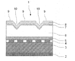
- FIG. 1 is a cross-sectional view showing an example of the sheet of the present invention.
- the sheet 1 of the present invention illustrated in FIG. 1 includes a flat portion 9 having a concavo-convex shape formed by the above-described extender pigment on the surface, and a wood grain plate conduit groove 10 is formed between the flat portions 9. ing.
- the other embossed shapes are not limited to the wood grain plate conduit grooves, and examples thereof include stone plate surface irregularities (such as granite cleaved surfaces), cloth surface textures, satin texture, sand texture, hairlines, and ridges.
- the sheet of the present invention has a reflectivity at a regular reflection angle of ⁇ 5 °, measured when the surface is irradiated with incident light having an incident angle of 75 ° by a goniophotometer. 50% or less.
- the reflectance at the regular reflection angle of ⁇ 5 ° is preferably 40% or less of the reflectance at the regular reflection angle.
- the lower limit of the ratio of the reflectance at the regular reflection angle ⁇ 5 ° to the reflectance at the regular reflection angle is not particularly limited, and it is preferably as small as possible.
- the surface 60 ° gloss of the sheet of the present invention is preferably 10 or less, and more preferably 7 or less.
- the 60 ° gloss is a value measured using a gloss measuring device (trade name: GMX-202, manufactured by Murakami Color Research Laboratory Co., Ltd.) according to a method in accordance with JIS Z-8741. It is.
- the thickness of the sheet of the present invention is preferably 50 to 600 ⁇ m, and more preferably 100 to 250 ⁇ m. By setting the thickness within the above-described range, the sheet of the present invention is more excellent in design properties and can be provided with scratch resistance.
- the specific structure will not be limited.
- the sheet of the present invention is a decorative sheet, a sheet formed by sequentially laminating a pattern layer, a transparent adhesive layer, a transparent resin layer, a primer layer, and a surface protective layer on the base sheet is exemplified. .
- the base sheet is a layer in which a pattern layer or the like is sequentially laminated on the surface (front surface).
- a sheet (film) formed of a thermoplastic resin is suitable.
- a thermoplastic resin Specifically, polyvinyl chloride, polyethylene terephthalate, polybutylene terephthalate, polyamide, polyethylene, polypropylene, polycarbonate, polyethylene naphthalate, ethylene / vinyl acetate copolymer, ethylene / acrylic acid copolymer, ethylene / acrylic acid ester copolymer Examples include polymers, ionomers, acrylic esters, and methacrylic esters.
- the said base material sheet is formed by using these resin individually or in combination of 2 or more types.
- the base sheet may be colored.
- a coloring material pigment or dye
- a coloring material for coloring
- the colorant for example, inorganic pigments such as titanium dioxide, carbon black and iron oxide, organic pigments such as phthalocyanine blue, and various dyes can be used. These can be selected from one or more known or commercially available ones. Further, the addition amount of the colorant may be appropriately set according to the desired color tone.
- the base sheet contains various additives such as fillers, matting agents, foaming agents, flame retardants, lubricants, antistatic agents, antioxidants, UV absorbers, and light stabilizers as necessary. It may be.
- the thickness of the substrate sheet can be appropriately set depending on the use of the final product, the method of use, etc., but generally 20 to 300 ⁇ m is preferable.
- the base sheet may be subjected to corona discharge treatment on the surface (front surface) as necessary in order to enhance the adhesion of the ink for forming the pattern layer.
- corona discharge treatment on the surface (front surface) as necessary in order to enhance the adhesion of the ink for forming the pattern layer.
- What is necessary is just to implement the method and conditions of a corona discharge process according to a well-known method.
- Pattern pattern layer is a layer that imparts a desired pattern (design) to the sheet, and the type of pattern is not limited. For example, a wood grain pattern, a leather pattern, a stone pattern, a grain pattern, a tiled pattern, a brickwork pattern, a cloth pattern, a geometric figure, a character, a symbol, an abstract pattern, and the like can be given.
- the method for forming the pattern layer is not particularly limited.
- an ink obtained by dissolving (or dispersing) a known colorant (dye or pigment) in a solvent (or dispersion medium) together with a binder resin is used. What is necessary is just to form on the base-material sheet
- an aqueous composition can be used from the viewpoint of reducing the VOC of the sheet.
- the colorant examples include inorganic pigments such as carbon black, titanium white, zinc white, dial, bitumen, and cadmium red; azo pigments, lake pigments, anthraquinone pigments, quinacridone pigments, phthalocyanine pigments, isoindolinone pigments, dioxazine pigments.
- Organic pigments such as aluminum powder, metal powder pigments such as bronze powder, pearlescent pigments such as titanium oxide-coated mica and bismuth oxide chloride; fluorescent pigments; These colorants can be used alone or in admixture of two or more. These colorants may be used together with fillers such as silica, extender pigments such as organic beads, neutralizing agents, surfactants and the like.
- binder resin in addition to polyester-based urethane resin treated with hydrophilicity, polyester, polyacrylate, polyvinyl acetate, polybutadiene, polyvinyl chloride, chlorinated polypropylene, polyethylene, polystyrene, polystyrene-acrylate copolymer, rosin derivative
- an alcohol adduct of styrene-maleic anhydride copolymer, cellulose resin and the like can be used in combination. More specifically, for example, polyacrylamide resins, poly (meth) acrylic resins, polyethylene oxide resins, poly N-vinyl pyrrolidone resins, water-soluble polyester resins, water-soluble polyamide resins, water-soluble amino acids.
- water-based resins water-soluble phenolic resins, other water-soluble synthetic resins; water-soluble natural polymers such as polynucleotides, polypeptides, polysaccharides, and the like.
- water-soluble natural polymers such as polynucleotides, polypeptides, polysaccharides, and the like.
- natural rubber, synthetic rubber, polyvinyl acetate resin, (meth) acrylic resin, polyvinyl chloride resin, polyurethane-polyacrylic resin, etc. modified or a mixture of natural rubber, etc. Resin can also be used.
- the said binder resin can be used individually or in combination of 2 or more types.
- the thickness of the pattern layer is not particularly limited and can be appropriately set according to the product characteristics.
- the layer thickness at the time of coating is about 1 to 15 ⁇ m, and the layer thickness after drying is about 0.1 to 10 ⁇ m.
- seat of this invention is a structure which does not have a pattern pattern layer
- seat of this invention is made transparent, the pattern of adherends, such as a wooden base material, will be visible through the said sheet
- the pattern of the adherend can be used as a design as it is.
- the design expressed by the pattern of the adherend is excellent in low gloss by the sheet of the present invention, and the irregular reflection of light on the surface of the sheet is suppressed even when viewed from an oblique direction. Is visible and can exhibit excellent design properties.
- an adhesive layer may be formed on the design pattern layer.
- the adhesive layer is preferably a transparent adhesive layer, and the transparent adhesive layer includes any of colorless and transparent, colored and transparent, and translucent.
- the adhesive is not particularly limited, and an adhesive known in the field of decorative sheets can be used.
- known adhesives in the field of decorative sheets include thermoplastic resins such as polyamide resins, acrylic resins and vinyl acetate resins, and thermosetting resins such as urethane resins. These adhesives can be used individually by 1 type or in combination of 2 or more types. Further, a two-component curable polyurethane resin or polyester resin using isocyanate as a curing agent can also be applied.
- the thickness of the adhesive layer is not particularly limited, but the thickness after drying is about 0.1 to 30 ⁇ m, preferably about 1 to 20 ⁇ m.
- the transparent resin layer is not particularly limited as long as it is transparent, and includes any of colorless and transparent, colored and transparent, and translucent.
- the resin constituting the transparent resin layer include polyethylene terephthalate, polybutylene terephthalate, polyamide, polyethylene, polypropylene, ethylene / vinyl acetate copolymer, ethylene / acrylic acid copolymer, and ethylene / acrylic acid ester copolymer.
- Examples thereof include coalescence, ionomer, polymethylpentene, acrylic acid ester, methacrylic acid ester, polycarbonate, and cellulose triacetate. These resins can be used alone or in combination of two or more.
- a polyolefin resin typified by polypropylene resin is used. Therefore, when using polyolefin-type resin as a transparent resin layer, the various polyolefin-type resin quoted as what comprises a base material sheet can be used.
- the transparent resin layer may be colored as long as it has transparency, but it is particularly desirable not to add a colorant.
- the thickness of the transparent resin layer is usually about 20 to 200 ⁇ m, but may exceed the above range depending on the use of the sheet.
- the transparent resin layer is the outermost layer of the sheet, and the uneven shape of the sheet of the present invention is formed on the surface of the transparent resin layer. It is preferable.
- the method for forming the uneven shape of the sheet of the present invention on the surface of the transparent resin layer include a method of forming the above uneven shape on the surface of the transparent resin layer with an embossed plate.
- a primer layer may be provided on the primer layer transparent resin layer.
- the primer layer can be formed by applying a known primer agent to the surface of the transparent resin layer.
- the primer agent include a urethane resin primer agent made of an acrylic-modified urethane resin (acrylic urethane resin), a urethane-cellulose resin (for example, a resin obtained by adding hexamethylene diisocyanate to a mixture of urethane and nitrified cotton) ), A resinous primer agent made of a block copolymer of acrylic and urethane, and the like. You may mix
- the additive examples include fillers such as calcium carbonate and clay, flame retardants such as magnesium hydroxide, antioxidants, lubricants, foaming agents, ultraviolet absorbers, and light stabilizers.
- the blending amount of the additive can be appropriately set according to the product characteristics.
- the application amount of the primer agent is not particularly limited, but is usually 0.1 to 100 g / m 2 , preferably about 0.1 to 50 g / m 2 .
- the thickness of the primer layer is not particularly limited, but is usually about 0.01 to 10 ⁇ m, preferably about 0.1 to 1 ⁇ m.
- the resin constituting the surface protective layer is preferably a curable resin such as a thermosetting resin or an ionizing radiation curable resin (for example, an electron beam curable resin).
- a curable resin such as a thermosetting resin or an ionizing radiation curable resin (for example, an electron beam curable resin).
- ionizing radiation curable resins are preferable from the viewpoint of high surface hardness, productivity, and the like.
- thermosetting resins include unsaturated polyester resins, polyurethane resins (including two-component curable polyurethane), epoxy resins, amino alkyd resins, phenol resins, urea resins, diallyl phthalate resins, melamine resins, guanamine resins, and melamines.
- unsaturated polyester resins polyurethane resins (including two-component curable polyurethane)
- epoxy resins include epoxy resins, amino alkyd resins, phenol resins, urea resins, diallyl phthalate resins, melamine resins, guanamine resins, and melamines.
- -Urea cocondensation resin silicon resin, polysiloxane resin and the like.
- a curing agent such as a crosslinking agent and a polymerization initiator and a polymerization accelerator can be added to the resin.
- curing agents isocyanates, organic sulfonates, etc. can be added to unsaturated polyester resins, polyurethane resins, etc., organic amines, etc. can be added to epoxy resins, peroxides such as methyl ethyl ketone peroxide, azoisobutyl nitrile, etc.
- a radical initiator can be added to the unsaturated polyester resin.
- Examples of the method of forming the surface protective layer with a thermosetting resin include a method in which a solution of a thermosetting resin is applied by a coating method such as a roll coating method or a gravure coating method, followed by drying and curing.
- the ionizing radiation curable resin is not limited as long as it is a resin that undergoes a crosslinking polymerization reaction upon irradiation with ionizing radiation and changes to a three-dimensional polymer structure.
- one or more prepolymers, oligomers, and monomers having a polymerizable unsaturated bond or epoxy group that can be cross-linked by irradiation with ionizing radiation in the molecule can be used.
- examples thereof include acrylate resins such as urethane acrylate, polyester acrylate, and epoxy acrylate; silicon resins such as siloxane; polyester resins; epoxy resins and the like.
- Ionizing radiation includes visible light, ultraviolet light (near ultraviolet light, vacuum ultraviolet light, etc.), X-rays, electron beams, ion beams, etc. Among them, ultraviolet light and / or electron beams are desirable.
- an ultra-high pressure mercury lamp As the ultraviolet light source, an ultra-high pressure mercury lamp, a high pressure mercury lamp, a low pressure mercury lamp, a carbon arc lamp, a black light fluorescent lamp, or a metal halide lamp can be used.
- the wavelength of ultraviolet light is about 190 to 380 nm.
- the electron beam source for example, various electron beam accelerators such as a cockcroft-wald type, a bandegraft type, a resonant transformer type, an insulating core transformer type, a linear type, a dynamitron type, and a high frequency type can be used.
- the energy of the electron beam is preferably about 100 to 1000 keV, more preferably about 100 to 300 keV.
- the irradiation amount of the electron beam is preferably about 2 to 15 Mrad.
- the ionizing radiation curable resin is sufficiently cured when irradiated with an electron beam, but it is preferable to add a photopolymerization initiator (sensitizer) when cured by irradiation with ultraviolet rays.
- a photopolymerization initiator sensitizer
- Photopolymerization initiators in the case of resin systems having radically polymerizable unsaturated groups include, for example, acetophenones, benzophenones, thioxanthones, benzoin, benzoin methyl ether, Michler benzoylbenzoate, Michler ketone, diphenyl sulfide, dibenzyl disulfide , Diethyl oxide, triphenylbiimidazole, isopropyl-N, N-dimethylaminobenzoate and the like can be used.
- a resin system having a cationic polymerizable functional group for example, at least one kind such as an aromatic diazonium salt, an aromatic sulfonium salt, a metallocene compound, a benzoin sulfonic acid ester, and a freeloxysulfoxonium diallyl iodosyl salt.
- an aromatic diazonium salt an aromatic sulfonium salt, a metallocene compound, a benzoin sulfonic acid ester, and a freeloxysulfoxonium diallyl iodosyl salt.
- the addition amount of the photopolymerization initiator is not particularly limited, but is generally about 0.1 to 10 parts by mass with respect to 100 parts by mass of the ionizing radiation curable resin.
- a solution of an ionizing radiation curable resin may be applied by a coating method such as a gravure coating method or a roll coating method.
- the thickness of the surface protective layer is usually about 0.1 to 50 ⁇ m, preferably about 1 to 20 ⁇ m.
- additives such as solvents, dyes, extender pigments, fillers such as extenders, antifoaming agents, leveling agents, and thixotropic agents can be added to the surface protective layer as necessary.
- the extender pigment added to the surface protective layer is not particularly limited as long as it does not impair the design properties expressed by the sheet of the present invention, and known or commercially available pigments can be used.
- inorganic fine particles such as silica fine particles, silicone resin, talc, clay, barium sulfate, barium carbonate, calcium sulfate, calcium carbonate, and magnesium carbonate can be used.
- silica fine particles are preferable from the viewpoint of excellent scratch resistance.
- the amount of the extender added to the surface protective layer is preferably 5 to 50 parts by mass, more preferably 10 to 30 parts by mass with respect to 100 parts by mass of the resin solid content of the resin forming the surface protective layer.
- the average particle size of the extender pigment is preferably 0.5 to 35 ⁇ m, more preferably 2 to 14 ⁇ m.
- the surface of the surface protective layer can be formed into an uneven shape with which the sheet of the present invention is provided, and the surface of the surface protective layer has a low gloss feeling. And can have the stain resistance and scratch resistance required for the surface of the sheet.
- the average particle diameter of the extender pigment is preferably smaller than the thickness of the surface protective layer.
- the surface protective layer may further contain resin beads.
- the surface protective layer contains resin beads, white turbidity of the surface protective layer due to the inclusion of the extender pigment or the like can be suppressed.
- the resin beads are not particularly limited, and examples thereof include acrylic beads, urethane beads, polyethylene beads, polypropylene beads, polycarbonate beads, polyvinyl chloride beads, melamine beads, nylon beads, and styrene-acrylic copolymer beads. Among these, acrylic beads are preferable in terms of excellent transparency.
- the amount of the resin beads added to the surface protective layer is preferably 2 to 40 parts by mass, more preferably 4 to 30 parts by mass with respect to 100 parts by mass of the resin solid content of the resin forming the surface protective layer.
- the average particle diameter of the resin beads is preferably 0.5 to 20 ⁇ m, more preferably 2 to 14 ⁇ m. By setting the average particle diameter of the resin beads within such a range, the cloudiness of the surface protective layer can be further suppressed.
- the average particle diameter of the resin beads is preferably smaller than the thickness of the surface protective layer.
- the surface shape of the sheet of the present invention may be changed to the above-described uneven shape by a method of forming the above-described uneven shape with an embossed plate on the sheet surface. .
- seat of this invention as the above-mentioned uneven
- the surface protective layer is preferably formed adjacent to the gloss adjusting layer.
- the back surface and / or side surface of the surface protective layer is preferably adjacent to the gloss adjusting layer.
- a surface protective layer is transparent.
- the surface protective layer preferably contains fine particles A having a particle diameter equal to or smaller than the thickness of the surface protective layer and fine particles B having a particle diameter larger than the thickness of the surface protective layer as extender pigments.
- the fact that the particle diameter of the fine particles A is equal to or smaller than the thickness of the surface protective layer and that the particle diameter of the fine particles B is larger than the thickness of the surface protective layer are determined by SEM (scanning electron microscope). For example, it can be confirmed by cutting the sheet in a direction perpendicular to the surface and observing the portion of the surface protective layer of the obtained cross section using an SEM (scanning electron microscope).
- the particle diameter of the fine particles A is not particularly limited as long as it is not more than the thickness of the surface protective layer. If the particle diameter of the fine particles A exceeds the thickness of the surface protective layer, the matting effect may not be sufficient, and the fine particles A will cue from the surface protective layer, and the cue from the surface protective layer of the fine particles A will occur.
- the rubbed part may be rubbed and scraped, the gloss of the rubbed part may increase and become noticeable, and the scratch resistance may not be sufficient.
- the particle size of the fine particles A is preferably 3 to 15 ⁇ m, more preferably 8 to 12 ⁇ m. If the particle diameter of the fine particles A is too small, the matting effect may not be sufficient.
- the content of the fine particles A is preferably 5 to 30 parts by mass with respect to 100 parts by mass of the resin component of the surface protective layer. If the content of the fine particles A is too large, the fine particles A cued from the surface protective layer increase, and when the crushed portion is rubbed and scraped off, the gloss of the rubbed portions increases and becomes conspicuous. May not be enough. Further, if the content of the fine particles A is too small, the matting effect may not be sufficient.
- the content of the fine particles A is preferably 10 to 20 parts by mass with respect to 100 parts by mass of the resin component of the surface protective layer.
- the particle diameter of the fine particles B is not particularly limited as long as it is larger than the thickness of the surface protective layer.
- the surface protective layer may not have sufficient scratch resistance.
- the particle diameter of the fine particles B is preferably 8 to 33 ⁇ m, and more preferably 8 to 20 ⁇ m. If the particle diameter of the fine particles B is too large, the fine particles B may be easily detached from the surface protective layer.
- the content of the fine particles B is preferably 5 to 30 parts by mass with respect to 100 parts by mass of the resin component of the surface protective layer.
- the content of the fine particles B is preferably 10 to 20 parts by mass with respect to 100 parts by mass of the resin component of the surface protective layer.
- the particle diameters of the fine particles A and B can be measured by SEM (scanning electron microscope). For example, a decorative sheet is cut in a direction perpendicular to the surface, and the surface of the obtained cross section is obtained. An arbitrary portion of the protective layer can be photographed using an SEM (scanning electron microscope) and measured by averaging the particle diameter of the fine particles A and the particle diameter (diameter) of the fine particles B. Average particle size.
- the total content of the fine particles A and the fine particles B is preferably 15 to 35 parts by mass with respect to 100 parts by mass of the resin component of the surface protective layer. If the total content of the fine particles A and the content of the fine particles B is too small, the surface protective layer may be inferior in scratch resistance and design properties (low glossiness). If the total content is too large, the fine particles When the portions A and B are cueing increase and the portions are rubbed and scraped, the gloss of the rubbed portion is increased and noticeable, and the scratch resistance may not be sufficient.
- the total content of the fine particles A and the fine particles B is preferably 20 to 35 parts by mass with respect to 100 parts by mass of the resin component of the surface protective layer.
- the fine particles A and B are not particularly limited as long as they can improve the scratch resistance of the surface protective layer according to the particle diameter and can improve the matting effect, and conventionally known ones can be used.
- the fine particles A and B include inorganic particles such as silica fine particles and silicone resins; organic particles such as crosslinked alkyl, crosslinked styrene, inzoguanamine resin, urea-formaldehyde resin, phenol resin, polyethylene, and nylon. .
- silica fine particles are preferable.
- Gloss control layer A gloss control layer may be formed on the sheet of the present invention.
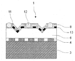
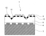
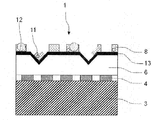
- Examples of the form of the sheet on which the gloss adjusting layer is formed include the forms shown in FIGS. 2 to 4, in the sheet 1 of the present invention, a pattern layer 4, a transparent resin layer 6, a gloss adjusting layer 13, and a surface protective layer 8 are laminated on a base sheet 3.
- the surface protective layer 8 contains fine particles A11 having a particle diameter equal to or smaller than the thickness of the surface protective layer 8 and fine particles B12 having a particle diameter larger than the thickness of the surface protective layer 8.
- the gloss adjusting layer is preferably formed on the transparent resin layer so as to be adjacent to the surface protective layer. More specifically, the back surface of the gloss adjusting layer is adjacent to the front surface of the transparent resin layer (or the primer layer when the sheet of the present invention has the primer layer), and The front surface and / or the side surface of the gloss adjusting layer is adjacent to the surface protective layer.
- the gloss adjustment layer may be formed on a part of the surface on the front surface side (the surface side that is visually recognized after the application of the sheet (decorative sheet) or the decorative plate) from the viewpoint of design, (2) It may be formed on the entire front surface (the entire surface). That is, the gloss adjustment layer may be (1) partially formed with respect to the front surface, and (2) formed over the entire surface with reference to the front surface. May be.
- the surface protective layer When the (1) gloss adjustment layer is formed on a part of the front side surface, (a) the surface protective layer may be formed on a part of the front side surface, (B) The surface protective layer may be formed on the entire front surface side.
- the surface protective layer is formed by the gloss adjusting layer. It is formed so as to fill a region that has not been formed (region that does not exist).
- the gloss adjusting layer is formed on a part of the surface on the front surface side, and the surface protective layer is formed on the entire surface on the front surface side ((1) ( b)).
- the gloss adjusting layer is formed on a part of the surface on the front surface side, and the surface protective layer is formed on a part of the surface on the front surface side ((1) above) (Form of (a)).
- the surface protective layer is formed on a part of the front surface.
- the gloss adjusting layer is formed on the entire front surface side, and the surface protective layer is formed on a part of the front surface side (form (2) above. ).
- the gloss value of the gloss adjusting layer is G A
- the gloss value of the surface protective layer is GP .
- the relationship between the gloss values G A luster control layer and the luster value G P of the aforementioned surface protective layer is preferably a G P ⁇ G A.
- the G A and the G P in the present specification is a value measured according to Japanese Industrial Standard JIS Z8741.
- the gloss value is also referred to as a gloss value or a gloss value.
- the gloss adjustment layer is formed on a part of the front side surface or (2) the gloss adjustment layer is formed on the entire front side. Even on the surface visually recognized after the construction of the sheet (decorative sheet) or the decorative plate, both the gloss adjusting layer and the surface protective layer are visible, and each of the gloss adjusting layer and the surface protective layer is visible. It is preferred relationship gloss value is G P ⁇ G a. In this case, when the sheet (decorative sheet) of the present invention is adhered to an adherend, the influence of the uneven shape (duck) generated on the sheet surface is further suppressed, and the design of the sheet or decorative plate is improved. Therefore, the sheet
- the gloss adjusting layer is formed on a part of the surface on the front side (simply referred to as the case (1) above)
- the area ratio of the area where the gloss adjusting layer occupies per 1 cm 2 of the front surface area of the sheet (decorative sheet) or the decorative board is 20 to 80%. preferable.
- the gloss adjusting layer is formed so that the front surface (surface to be visually recognized) side of the gloss adjusting layer has a pattern shape.
- the gloss adjustment layer has a pattern shape and the ratio of the area is 20 to 80%, so that the gloss difference between the gloss adjustment layer and the surface protective layer becomes clearer, and as a result, the design is further improved, and Further, it is possible to further suppress the influence of the uneven shape (duck).
- the type of the pattern is not particularly limited. Specific examples of the pattern include those similar to the various patterns exemplified in the pattern pattern layer described above.
- the ratio of the area of the area (area where the gloss adjusting layer is present) where the gloss adjusting layer occupies per 1 cm 2 of the area of the front surface of the sheet (decorating sheet) or the decorative board is expressed as gloss. It may be referred to as the occupation area ratio of the adjustment layer.
- the occupation area ratio of the gloss adjusting layer is calculated from plate making data at the stage of producing a plate for forming the gloss adjusting layer.
- the area occupied by the gloss adjusting layer can also be calculated from the shape of the plate.
- the relationship between the G A and the G P is G A ⁇ G P Is preferred. More preferably, G A ⁇ GP and G A ⁇ 5.
- the mechanism by which the sheet of the present invention can exhibit excellent design properties has not yet been fully elucidated, but it is provided on the surface of the gloss adjusting layer in the case of (1) above.
- an uncured material such as a curable resin of the surface protective layer
- the resin component of the gloss adjusting layer and the uncured material of the surface protective layer are selected depending on the combination of materials and application conditions. Is presumed to be due to the development of some interactions such as elution, dispersion, and mixing. That is, the resin component in the uncured product such as the curable resin forming the surface protective layer and the ink of the gloss adjusting layer in the case of (1) is not completely compatible in a short time.
- the suspended state is present on or near the gloss adjusting layer, and the suspended portion scatters light to form a low gloss region.
- the surface protective layer is formed by crosslinking and curing while maintaining this suspended state, the region on the gloss adjusting layer in the case (1) in the surface protective layer is at least a low gloss region, By the illusion, it is presumed that the region is visually recognized as if it were a concave portion (hereinafter also referred to as “visual concave portion”).
- the outermost surface of the surface protective layer may be ) To form a convex shape (hereinafter also referred to as “convex shape by gloss adjusting layer”). Since the surface of the surface protective layer has such a convex shape by the gloss adjusting layer, light is scattered even in this portion, so that a further visual unevenness (hereinafter also referred to as “visual unevenness”) is provided. Emphasized and preferred.
- the height of the convex shape formed by the gloss adjusting layer is preferably a height within the range where the effects of the present invention are exerted, and is usually within a range of 2 to 3 ⁇ m.
- the surface protective layer is formed on a part of the surface on the front surface side.
- the surface protective layer is formed so that the front surface (surface to be visually recognized) side of the surface protective layer has a pattern shape.
- the gloss difference between the gloss adjusting layer and the surface protective layer becomes clearer, and as a result, the design property can be further improved and the influence of the uneven shape (duck) can be further suppressed.
- the type of the pattern is not particularly limited. Specific examples of the pattern include those similar to the various patterns exemplified in the pattern pattern layer described above.
- ⁇ 2 is preferable, and
- the relationship between the G A and the G P may be a G A ⁇ G P, or may be a G P ⁇ G A.
- the surface protective layer of the luster control layer may be a low gloss than it is the surface protective layer of the luster control layer, also towards the surface protective layer may be a low glossy than luster control layer (Incidentally, are G A ⁇ G P If a layer of the luster control layer is low luster, if a G P ⁇ G a surface protective layer is a layer of low gloss). In the case of (2), it is preferable that the ratio of the area of the region where the low-gloss layer is present per 1 cm 2 of the front surface area of the sheet (decorative sheet) or the decorative board exceeds 50%.
- the ratio of the area of the area (area where the surface protective layer is present) in which the surface protective layer occupies per 1 cm 2 of the area of the front surface of the sheet (decorative sheet) or the decorative board is defined as the surface It may be called the occupation area ratio of the protective layer.
- the occupation area ratio of the surface protective layer is calculated from plate-making data at the stage of producing a plate for forming the surface protective layer.
- the occupation area ratio of the surface protective layer can also be calculated from the shape of the plate.
- the ratio of the area where the low gloss layer is exposed per 1 cm 2 of the front surface area of the sheet (decorative sheet) or the decorative board (the exposed area ratio of the low gloss layer) is ( i)
- the occupied area ratio of the surface protective layer is the same as the occupied area ratio of the low gloss layer
- the low gloss layer is a gloss adjusting layer. Is obtained by subtracting (minus) the occupied area ratio of the surface protective layer from 100 (%) after calculating the occupied area ratio of the surface protective layer.
- the method for forming the gloss adjusting layer is not particularly limited.
- the gloss adjusting layer is dissolved (or dispersed) in a solvent (or dispersion medium) together with a known colorant (dye, pigment, etc.), vehicle, etc., in the same manner as the above-mentioned pattern layer. It can be formed with the ink obtained.
- a coloring agent and a solvent the thing similar to the coloring agent and solvent which were illustrated by the coloring agent and solvent in the above-mentioned pattern pattern layer, respectively can be used.
- the ink for forming the gloss adjusting layer preferably has a property of causing interaction with the curable resin composition (uncured curable resin) for forming the surface protective layer. It is appropriately selected in relation to the resin composition (uncured curable resin).
- the ink vehicle for forming the gloss adjusting layer preferably contains 50% by mass or more of urethane resin and / or polyvinyl acetal resin.
- the urethane resin includes a polyol component such as an acrylic polyol, a polyester polyol, and a polyether polyol, and an isocyanate component such as tolylene diisocyanate, xylene diisocyanate, diphenylmethane diisocyanate, and other aromatic isocyanates, isophorone diisocyanate, hexamethylene diisocyanate, Examples include urethane resins obtained by reacting with aliphatic or cycloaliphatic isocyanates such as hydrogenated tolylene diisocyanate (linearly cross-linked or network cross-linked).
- a polyvinyl acetal type resin is obtained by condensation (acetalization) of polyvinyl alcohol and aldehydes.
- the polyvinyl acetal resin include polyvinyl formal (formal resin), polyvinyl acetoacetal, polyvinyl propional, polyvinyl butyral (butyral resin), and polyvinyl hexyl.
- polyvinyl butyral is particularly preferable because it is soluble in a solvent, easily converted into an ink, and has a good appearance of visual unevenness (recognized visually as a recess).
- the ink for forming the gloss adjusting layer may be uncolored, but by coloring with a pigment, the visual concave portion becomes clearer, and the visual unevenness and depth are reduced. It can be set as the sheet
- the pigment to be colored is preferably an inorganic pigment because it is excellent in weather resistance and has a concealing property so that depth can be expressed and adhesion with the surface protective layer is good.
- the inorganic pigment may be a single color or a mixed color composed of two or more.
- a known pigment can be used, and the color (pigment) to be used depending on the pattern of the picture printing layer and the amount of addition may be appropriately determined.
- gloss adjusting resins such as unsaturated polyester resins, acrylic resins, and vinyl chloride-vinyl acetate copolymers may be mixed to adjust the gloss value.
- the mixing ratio is preferably in the range of 10 to 50% by mass with respect to the total amount of the vehicle.
- the surface protective layer is provided on the gloss adjusting layer, and the gloss adjusting layer is composed of an ink containing extender pigment and the curable resin constituting the surface protective layer. Even if it interacts with the composition (uncured curable resin) or the like, the region on the gloss adjustment layer becomes at least a low gloss region, and due to the illusion of eyes, the region is a recess (visual recess). It is preferable that it is recognized.
- the thickness of the gloss adjusting layer is suitably 0.5 ⁇ m or more and 5.0 ⁇ m or less in consideration of printability and interaction with the curable resin composition (uncured curable resin). .
- the extender pigment is not particularly limited, and is suitably selected from, for example, silica, talc, clay, barium sulfate, barium carbonate, calcium sulfate, calcium carbonate, magnesium carbonate and the like.
- silica which is a material having a high degree of freedom in material design such as oil absorption, particle size, pore volume, etc., and excellent in designability, whiteness, and coating stability as an ink, is preferable.
- Silica is preferred.
- the average particle diameter of silica used in the case of (1) may be determined in relation to the film thickness ( ⁇ m) of the gloss adjusting layer, and is generally about 1.0 ⁇ m or more, and the maximum particle diameter Should be determined in relation to the film thickness ( ⁇ m) of the surface protective layer, but the film thickness of the surface protective layer takes into account various physical properties required for the sheet (post-processing suitability and proper use) and cost. In general, it is 10.0 ⁇ m or less, preferably 7.0 ⁇ m or less, and the optimum range of the average particle diameter is 2.0 ⁇ m or more and 4.0 ⁇ m or less.
- the amount of the extender added to the ink for forming the gloss adjusting layer is preferably 5 to 15 parts by weight with respect to 100 parts by weight of the ink composition other than the extender. If it is less than 5 parts by weight, there is a possibility that sufficient thixotropy cannot be imparted to the printing ink composition forming the gloss adjusting layer, and if it exceeds 15 parts by weight, the effect of imparting low gloss may be reduced.
- Gloss values G A luster control layer, vehicle described above, luster control resin, a method for selecting a type of each substance and coloring agent (including extender pigments); and the like; how to set the contents of the above materials properly Can be adjusted.
- the printing method used for forming the gloss adjusting layer for example, the gravure printing method, the offset printing method, the screen printing method, the flexographic printing method, the electrostatic printing method, the inkjet method, and the like, as in the printing method used for forming the above-mentioned pattern pattern layer.
- the printing method etc. are mentioned.
- the method similar to the various coating methods in formation of a pattern layer is mentioned.
- the gloss adjustment layer is preferably formed so as to have a pattern shape.
- the gloss adjusting layer is more preferably formed in a pattern such as a dot shape, a lattice shape, or a wood grain conduit pattern (shape). Since the gloss adjustment layer is formed in the above pattern, the gloss of the area with the gloss adjustment layer is further different from the gloss of the area other than the gloss adjustment layer (area without the gloss adjustment layer). An optical illusion appears as if there is a recess (visual recess), and it is visually recognized as a unique stereoscopic effect. For this reason, the uneven shape (duck) becomes less noticeable.
- the gloss adjustment layer so as to be interlocked (tuned) with the pattern of the pattern pattern layer.
- the pattern layer is formed in a wood grain pattern
- a sheet having a more excellent design can be obtained by forming a gloss adjustment layer by pattern printing in a wood grain conduit pattern.
- the thickness (film thickness) of the gloss adjusting layer is preferably from 0.5 ⁇ m to 10 ⁇ m, more preferably from 0.5 ⁇ m to 7 ⁇ m, considering the printability and the interaction with the resin composition for forming the surface protective layer. More preferably, it is 5 ⁇ m to 5 ⁇ m.
- a back primer layer may be provided on the back surface of the back primer layer substrate sheet (the surface opposite to the surface on which the pattern layer is laminated).
- the sheet of the present invention is a decorative sheet, it is effective when a decorative sheet is produced by laminating the decorative sheet and an adherend.
- the back primer layer can be formed by applying a known primer to the base material sheet.
- the primer agent include a urethane resin-based primer agent made of an acrylic-modified urethane resin (acrylic urethane resin), a urethane-cellulose resin (for example, a resin obtained by adding hexamethylene diisocyanate to a mixture of urethane and nitrified cotton) ), A resinous primer agent made of a block copolymer of acrylic and urethane, and the like. You may mix
- the additive examples include fillers such as calcium carbonate and clay, flame retardants such as magnesium hydroxide, antioxidants, lubricants, foaming agents, ultraviolet absorbers, and light stabilizers.
- the blending amount of the additive can be appropriately set according to the product characteristics.
- the application amount of the primer agent is not particularly limited, but is usually 0.1 to 100 g / m 2 , preferably about 0.1 to 50 g / m 2 .
- the thickness of the back primer layer is not particularly limited, but is usually about 0.01 to 10 ⁇ m, preferably about 0.1 to 1 ⁇ m.
- the sheet of the present invention is excellent in low gloss, and the design expressed by the sheet is visible even when viewed from an oblique direction, and exhibits excellent design properties, and therefore can be suitably used as a decorative sheet.
- the use of such a decorative sheet is not particularly limited and can be used for various applications requiring design properties.
- a decorative sheet for flooring used for flooring or a wall used for wall covering It is useful as a decorative sheet for equipment.
- a laminate can be obtained by laminating the decorative sheet on an adherend.
- the adherend is not limited, and the same materials as those used for known decorative panels can be used.
- the adherend include wood materials, metals, ceramics, plastics, and glass.
- the decorative sheet can be suitably used for a wood material.
- wood materials include veneer, wood veneer, wood plywood, particle board, medium density fiberboard (MDF) made from various materials such as cedar, firewood, firewood, pine, lawan, teak, and melapie. , Chip boards, or composite substrates on which chip boards are laminated.
- wood plywood, particle board, medium density fiber board (MDF) is preferably used as the wood material.
- the lamination method of laminating the decorative sheet and the adherend is not limited, and for example, a method of sticking the decorative sheet to the adherend with an adhesive can be employed. What is necessary is just to select an adhesive agent suitably from well-known adhesive agents according to the kind etc. of to-be-adhered material. Examples thereof include polyvinyl acetate, polyvinyl chloride, vinyl chloride / vinyl acetate copolymer, ethylene / acrylic acid copolymer, ionomer, butadiene / acrylonitrile rubber, neoprene rubber, natural rubber and the like. These adhesives are used alone or in combination of two or more.
- the decorative board manufactured in this way includes, for example, interior materials for buildings such as walls, ceilings, and floors; exterior materials such as balconies and verandas; surface decorative boards and furniture for furniture such as window frames, doors, and handrails; Alternatively, it can be used for a surface decorative plate of a cabinet such as a light electric or OA device. In particular, the decorative board can be suitably used as a floor decorative material.
- the sheet of the present invention has a surface arithmetic average roughness Ra (JIS B 0633: 2001) of 0.7 ⁇ m or less, and is measured when incident light with an incident angle of 75 ° is irradiated on the surface by a goniophotometer. Since the reflectance at the detection angle of regular reflection angle ⁇ 5 ° is 50% or less of the reflectance at the regular reflection angle, it is excellent in low gloss and is diffusely reflected even when oblique light is incident on the surface. Is suppressed, the surface is hard to look white when viewed from an oblique direction, the design to be expressed is visible, and exhibits excellent design properties.
- Ra surface arithmetic average roughness
- Example 1 As a base material sheet, a 60 ⁇ m-thick polypropylene film having both sides subjected to corona discharge treatment was prepared. A back primer layer having a thickness of 2 ⁇ m was formed by applying a two-component curable urethane resin to the back surface of the polypropylene film.
- a pattern pattern layer having a thickness of 2 ⁇ m was formed on the front surface of the polypropylene film by gravure printing using a printing ink made of a two-component curable acrylic urethane resin.
- a two-component curable urethane resin adhesive was applied such that the solid content was 3 g / m 2 to form an adhesive layer having a thickness of 3 ⁇ m.
- a polypropylene resin was heated and melt extruded using a T-die extruder to form a transparent resin layer having a thickness of 80 ⁇ m.
- a two-component curable urethane resin was applied so that the solid content was 1 g / m 2, and a primer layer (primer layer for forming a surface protective layer, thickness 2 ⁇ m) ) was formed.
- a urethane acrylate electron beam curable resin (EB resin) resin composition containing 15 parts by mass of silica fine particles having an average particle diameter of 3 ⁇ m with respect to 100 parts by mass of the resin solid content.
- the electron beam irradiation apparatus was applied in an environment with an oxygen concentration of 200 ppm or less after coating by a roll coating method so that the solid content of the resin composition was 15 g / m 2 and the thickness (layer thickness) after curing was 15 ⁇ m.
- a surface protective layer was formed by irradiating an electron beam under the conditions of an acceleration voltage of 125 KeV and 5 Mrad using this to cure the electron beam curable resin, and a decorative sheet (total thickness: 164 ⁇ m) was produced.
- Example 2 was carried out in the same manner as in Example 1 except that the surface protective layer contained 5 parts by mass of acrylic beads having a particle diameter of 3 ⁇ m in addition to silica fine particles with respect to 100 parts by mass of the resin solid content. A sheet of was prepared.
- Example 3 Particles whose surface protective layer is an extender having 10 parts by mass of fine particles A (average particle diameter of 3 ⁇ m) having a particle diameter equal to or smaller than the thickness of the surface protective layer with respect to 100 parts by mass of the resin solid content and larger than the thickness of the surface protective layer
- a sheet of Example 3 was produced in the same manner as in Example 1 except that 10 parts by mass of fine particles B having an average diameter (average particle diameter of 16 ⁇ m) were contained with respect to 100 parts by mass of the resin solid content.
- Example 4 Preparation of gloss adjustment layer forming ink 7 parts by mass of silica particles having 7.5 parts by mass of ocher (iron oxide) as a coloring pigment and 100 parts by mass of colored ink using a polyvinyl butyral resin as a vehicle (6.0 parts by mass as a resin component) A gloss adjusting layer forming ink was prepared by mixing the parts.
- the gloss adjusting layer forming ink was applied to the entire front surface of the primer layer by a gravure printing method to form a gloss adjusting layer.
- Surface protection was formed in the same manner as in Example 1 except that the thickness, the average particle diameter of silica, the surface Ra, and the ratio of reflectance were changed as shown in Table 2 on the front surface of the gloss adjusting layer. .
- a sheet of Example 4 was produced in the same manner as Example 1 except for the above.
- Example 5 The gloss adjusting layer-forming ink prepared in the same manner as in Example 4 was applied to the front surface of the primer layer in the form of a conduit pattern by gravure printing to form a gloss adjusting layer.
- Surface protection was formed in the same manner as in Example 1 except that the thickness, the average particle diameter of silica, the surface Ra, and the ratio of reflectance were changed as shown in Table 2 over the entire surface on which the gloss adjusting layer was formed.
- a sheet of Example 5 was produced in the same manner as Example 1 except for the above.
- Comparative Example 1 Implementation was performed except that the average particle diameter of the silica fine particles used for the surface protective layer was 10 ⁇ m, and the uneven shape formed on the surface of the sheet by the silica fine particles that contributed to the design and imparted touch was changed as shown in Table 1. In the same manner as in Example 1, a sheet of Comparative Example 1 was produced.
- Ra (arithmetic mean roughness) It measured by the measuring method based on JISB0633: 2001. The measurement was performed using SURFCOM FLEX-50A (manufactured by Tokyo Seimitsu Co., Ltd.).
- Ratio of reflectance at regular reflection angle ⁇ 5 ° with respect to reflectance at regular reflection angle Incident incident at an incident angle of 75 ° using a variable angle photometer (trade name: GC5000L, manufactured by Nippon Denshoku Industries Co., Ltd.)
- the reflectance at the regular reflection angle and the reflectance at the regular reflection angle ⁇ 5 ° were measured.
- the incident angle and the regular reflection angle are angles of incident light and reflected light with respect to the normal line of the sheet surface.
- the reflectance at the regular reflection angle of ⁇ 5 ° with respect to the reflectance at the regular reflection angle is calculated according to the following formula. The percentage was calculated.
- [Ratio of reflectance at regular reflection angle ⁇ 5 ° to reflectance at regular reflection angle (%)] [(Reflectance at regular reflection angle ⁇ 5 ° (%)) / (Reflectance at regular reflection angle (%))] ⁇ 100
- the visibility of the pattern on the pattern evaluation visibility sheet was evaluated. Specifically, the state of the decorative sheet surface was visually observed from an angle of 60 ° or more (oblique light) and an angle of 0 ° (front) with respect to the normal of the sheet surface. Based on the observation results, evaluation was performed according to the following evaluation criteria.
- X It is shining white by oblique observation and the pattern is not visible.
- ⁇ More than 90% of the subjects evaluated that the texture of the wood could be expressed
- ⁇ More than 70% of the subjects evaluated that the texture of the wood could be expressed
- ⁇ More than 50% of the subjects more than 70% Less than 50% of the subjects evaluated that the wood texture could be expressed.
Abstract
本発明は、低艶感に優れ、且つ、表面に斜光が入射しても光の乱反射が抑制され、斜めから見た際に表面が白く見え難く、表現する意匠が視認可能であり、意匠性に優れたシートを提供する。 表面の算術平均粗さRa(JIS B0633:2001)が0.7μm以下であり、 変角光度計により、表面に入射角75°の入射光を照射した際に測定される、正反射角±5°の検出角での反射率が、正反射角での反射率の50%以下である、 ことを特徴とするシート。
Description
本発明は、シートに関する。
従来、様々な物品の表面には、意匠性を付与するためにシートが積層されている。例えば、建築物の壁面に用いられる壁装材や、床面に用いられる床用化粧材等の内装材の表面には、木目柄等の絵柄模様が印刷された化粧シートが積層され、用いられている。このような内装材は、天然木の内装材の代替として用いられる。
上述のような物品の表面に積層されるシートには、意匠性を向上させるために、表面の艶を抑制することが要求される。表面の艶が高いと蛍光灯等の照明器具の光が反射して質感が低下し、また、反射した光により白く光って見えるという問題がある。
このような問題を解消した化粧シートとして、最表面層が艶消しフィラーを含有する電離放射線硬化型樹脂により形成された化粧シートが提案されている(例えば、特許文献1及び2参照)。
このような化粧シートも低艶感に優れ、光の反射の抑制に優れたシートではあるが、表面での光の反射の抑制については検討の余地があり、更なる意匠性が求められている。特に、シートを平面の被着材上に積層した場合、当該平面に照明器具等から斜光が入射すると、光を乱反射して、斜めから見た際に白く光って見えてしまい、絵柄等のシートが表現する意匠が視認し難くなり、意匠性が低下するという問題がある。特に、このようなシートは天然木の内装材の表面と比較して、表面に斜光が入射すると、斜めから見た際に白く光って見える角度が広く、意匠が視認し難い。このため、このようなシートには、表面に斜光が入射しても光の乱反射が抑制され、斜めから見た際に表面が白く見え難く、表現する意匠が視認可能であることが要求される。
従って、低艶感に優れ、且つ、表面に斜光が入射しても光の乱反射が抑制され、斜めから見た際に表面が白く見え難く、表現する意匠が視認可能であり、意匠性に優れたシートの開発が望まれている。
本発明は、低艶感に優れ、且つ、表面に斜光が入射しても光の乱反射が抑制され、斜めから見た際に表面が白く見え難く、表現する意匠が視認可能であり、意匠性に優れたシートを提供することを目的とする。
本発明者等は、鋭意研究を重ねた結果、シートの表面の算術平均粗さRa(JIS B0633:2001)を特定の範囲とし、変角光度計により、表面に入射角75°の入射光を照射した際に測定される、正反射角+5°の検出角での反射率、及び正反射角-5°の検出角での反射率を特定の範囲とすることにより、上記目的を達成できることを見出し、本発明を完成するに至った。
即ち、本発明は、下記のシートに関する。
1.表面の算術平均粗さRa(JIS B0633:2001)が0.7μm以下であり、
変角光度計により、表面に入射角75°の入射光を照射した際に測定される、正反射角±5°の検出角での反射率が、正反射角での反射率の50%以下である、
ことを特徴とするシート。
2.電離放射線硬化型樹脂を含有する表面保護層を最表面に有する、上記項1に記載のシート。
3.前記表面保護層は、シリカ微粒子及び樹脂ビーズを含有する、上記項2に記載のシート。
4.ポリオレフィン系樹脂を含有する透明性樹脂層を有する、上記項1~3のいずれかに記載のシート。
5.絵柄模様層を有する、上記項1~4のいずれかに記載のシート。
6.基材シート上に、少なくとも前記絵柄模様層、前記透明性樹脂層及び前記表面保護層がこの順に積層されている、上記項5に記載のシート。
7.厚みが50~600μmである、上記項1~6のいずれかに記載のシート。
8.化粧シートである、上記項1~7のいずれかに記載のシート。
9.床材用化粧シートである、上記項1~7のいずれかに記載のシート。
本発明のシートは、表面の算術平均粗さRa(JIS B0633:2001)が0.7μm以下であり、変角光度計により、表面に入射角75°の入射光を照射した際に測定される、正反射角±5°の検出角での反射率(以下、単に「正反射角±5°での反射率」ともいう)が、正反射角での反射率の50%以下である。なお、本明細書において、入射角、及び正反射角は、シートの表面の法線に対する入射光、及び反射光の角度である。
本発明のシートは、表面が上述の構成を備えているので、低艶感に優れ、表面に斜光が入射しても斜めから見た際にシート表面の光の乱反射が抑制されている。通常表面が低艶感を示すシートであっても、斜めから見ると光が乱反射し、シート表面の特定の箇所が白く見えてしまい、シートが本来表現する意匠が視認できない。これに対し、本発明のシートは、表面の算術平均粗さRaが0.7μm以下であり、且つ、表面に入射角75°の入射光を照射した際に測定される、上記正反射角±5°での反射率が、正反射角での反射率の50%以下であるとの構成を備えるので、シート表面での入射光の乱反射が抑制されており、本発明のシートの表面を、入射光の正反射角から±5°程度にわずかな角度ずれて見るだけで、絵柄等のシートが表現する意匠が視認可能である。このため、本発明のシートは、優れた意匠性を示すことができる。
以下、本発明のシートについて詳細に説明する。なお、本発明のシートにおいて、表面とは、いわゆる「おもて面」であり、本発明のシートが被着材等に積層して用いられる際に、被着材と接触する面とは反対側の面であり、積層後に視認される面である。また、本明細書では、本発明のシートについて、上記表面の方向を「おもて」又は「上」と称し、その反対側を「裏」又は「下」と称する場合がある。
[シート]
本発明のシートは、JIS B0633:2001に準拠して測定した表面の算術平均粗さRaが0.7μm以下である。上記Raが0.7μmを超えると、シート表面で入射光が乱反射し易くなり、正反射角±5°での反射率を、正反射角での反射率の50%以下に調整することが困難となり、表面に斜光が入射すると光が乱反射して斜めから見た際にシート表面の特定の箇所が白く見えてしまい、シートが本来表現する意匠が視認できない。上記Raは、0.6μm以下が好ましい。
本発明のシートは、JIS B0633:2001に準拠して測定した表面の算術平均粗さRaが0.7μm以下である。上記Raが0.7μmを超えると、シート表面で入射光が乱反射し易くなり、正反射角±5°での反射率を、正反射角での反射率の50%以下に調整することが困難となり、表面に斜光が入射すると光が乱反射して斜めから見た際にシート表面の特定の箇所が白く見えてしまい、シートが本来表現する意匠が視認できない。上記Raは、0.6μm以下が好ましい。
なお、本明細書において、後述する体質顔料、樹脂ビーズ、エンボス賦型等により表面の算術平均粗さRaを0.7μm以下に調整することによりシートの表面に形成された、意匠性に寄与し、触感を付与する凹凸形状を、単に「凹凸形状」と示し、後述するダクによる凹凸形状を表す「凹凸形状(ダク)」;視覚的に凹凸として認識される、「視覚凹部」、「視覚的凹凸感」;「艶調整層による凸形状」とは区別される。
本発明のシートにおいて、表面の形状を上述の凹凸形状とする方法としては特に限定されず、例えば、最表面となる層にシリカ等の体質顔料を含有させる方法や、シート表面に算術平均粗さRa(JIS B0633:2001)が0.7μm以下となるような凹凸形状をエンボス版により賦型する方法等が挙げられる。
本発明のシートは、表面に上述の凹凸形状を備えるものであるが、本発明の効果を妨げない範囲であれば、図1のように木目板導管溝等の他のエンボス形状が賦型されていてもよい。図1は、本発明のシートの一例を示す断面図である。図1に例示する本発明のシート1は、表面に上述の体質顔料等により形成された凹凸形状を備える平面部9を備えており、平面部9の間に木目板導管溝10が賦型されている。上記他のエンボス形状としては、木目板導管溝に限定されず、例えば、石板表面凹凸(花崗岩劈開面等)、布表面テクスチャア、梨地、砂目、ヘアライン、万線条溝等が挙げられる。
本発明のシートは、変角光度計により、表面に入射角75°の入射光を照射した際に測定される、正反射角±5°での反射率が、正反射角での反射率の50%以下である。上記正反射角±5°での反射率の、正反射角での反射率に対する割合が50%を超えると、斜光が入射した場合にシート表面の光の乱反射を十分に抑制できず、シートを斜めから見た際に、シートが表現する意匠を視認できない。上記正反射角±5°での反射率は、正反射角での反射率の40%以下が好ましい。また、上記正反射角±5°での反射率の、正反射角での反射率に対する割合の下限は特に限定されず、小さい程好ましい。
なお、本明細書において、反射率は変角光度計(日本電色工業株式会社製 商品名:GC5000L)を用いて入射光の入射角が75°の測定条件で測定された値である。また、上記正反射角での反射率に対する、正反射角±5°での反射率の割合は、下記式によって算出される値である。
[正反射角での反射率に対する、正反射角±5°での反射率の割合(%)]=
[(正反射角±5°での反射率(%))/(正反射角での反射率(%))]×100
[正反射角での反射率に対する、正反射角±5°での反射率の割合(%)]=
[(正反射角±5°での反射率(%))/(正反射角での反射率(%))]×100
本発明のシートは、表面の60°グロスが10以下であることが好ましく、7以下であることがより好ましい。本発明のシートの表面の60°グロスを上述の範囲とすることにより、低艶感により優れたシートとすることができる。なお、本明細書において、上記60°グロスは、JIS Z-8741に準拠した方法により、光沢度測定器(株式会社村上色彩技術研究所製 商品名:GMX-202)を用いて測定される値である。
本発明のシートは、厚みが50~600μmであることが好ましく、100~250μmであることがより好ましい。厚みを上述の範囲とすることにより、本発明のシートが意匠性により優れ、且つ耐擦傷性を備えることができる。
[シートの層構成]
本発明のシートは、表面の算術平均粗さRa(JIS B0633:2001)が0.7μm以下であれば、その具体的構成(層構成)については限定されない。例えば、本発明のシートが化粧シートである場合、基材シート上に、絵柄模様層、透明性接着剤層、透明性樹脂層、プライマー層及び表面保護層を順に積層してなるシートが挙げられる。
本発明のシートは、表面の算術平均粗さRa(JIS B0633:2001)が0.7μm以下であれば、その具体的構成(層構成)については限定されない。例えば、本発明のシートが化粧シートである場合、基材シート上に、絵柄模様層、透明性接着剤層、透明性樹脂層、プライマー層及び表面保護層を順に積層してなるシートが挙げられる。
以下、かかる層構成のシートを代表例として、各層について具体的に説明する。
基材シート
基材シートは、その表面(おもて面)に絵柄模様層等が順次積層される層である。基材シートとしては、例えば、熱可塑性樹脂により形成されたシート(フィルム)が好適である。具体的には、ポリ塩化ビニル、ポリエチレンテレフタレート、ポリブチレンテレフタレート、ポリアミド、ポリエチレン、ポリプロピレン、ポリカーボネート、ポリエチレンナフタレート、エチレン・酢酸ビニル共重合体、エチレン・アクリル酸共重合体、エチレン・アクリル酸エステル共重合体、アイオノマー、アクリル酸エステル、メタアクリル酸エステル等が挙げられる。前記基材シートは、これら樹脂を単独で又は2種以上を組み合わせ用いることにより形成される。
基材シートは、その表面(おもて面)に絵柄模様層等が順次積層される層である。基材シートとしては、例えば、熱可塑性樹脂により形成されたシート(フィルム)が好適である。具体的には、ポリ塩化ビニル、ポリエチレンテレフタレート、ポリブチレンテレフタレート、ポリアミド、ポリエチレン、ポリプロピレン、ポリカーボネート、ポリエチレンナフタレート、エチレン・酢酸ビニル共重合体、エチレン・アクリル酸共重合体、エチレン・アクリル酸エステル共重合体、アイオノマー、アクリル酸エステル、メタアクリル酸エステル等が挙げられる。前記基材シートは、これら樹脂を単独で又は2種以上を組み合わせ用いることにより形成される。
基材シートは、着色されていてもよい。この場合は、上記のような熱可塑性樹脂に対して着色材(顔料又は染料)を添加して着色することができる。着色材としては、例えば、二酸化チタン、カーボンブラック、酸化鉄等の無機顔料、フタロシアニンブルー等の有機顔料のほか、各種の染料も使用することができる。これらは、公知又は市販のものから1種又は2種以上を選ぶことができる。また、着色材の添加量も、所望の色合い等に応じて適宜設定すれば良い。
基材シートには、必要に応じて、充填剤、艶消し剤、発泡剤、難燃剤、滑剤、帯電防止剤、酸化防止剤、紫外線吸収剤、光安定化剤等の各種の添加剤が含まれていてもよい。
基材シートの厚みは、最終製品の用途、使用方法等により適宜設定できるが、一般には20~300μmが好ましい。
基材シートは、必要に応じて、絵柄模様層等を形成するインキの密着性を高めるために表面(おもて面)にコロナ放電処理を施してもよい。コロナ放電処理の方法・条件は、公知の方法に従って実施すれば良い。また、必要に応じて、基材シートの裏面にコロナ放電処理を施したり、後述する裏面プライマー層を形成したりしてもよい。
絵柄模様層
絵柄模様層は、シートに所望の絵柄(意匠)を付与する層であり、絵柄の種類等は限定的ではない。例えば、木目模様、レザー模様、石目模様、砂目模様、タイル貼模様、煉瓦積模様、布目模様、幾何学図形、文字、記号、抽象模様等が挙げられる。
絵柄模様層は、シートに所望の絵柄(意匠)を付与する層であり、絵柄の種類等は限定的ではない。例えば、木目模様、レザー模様、石目模様、砂目模様、タイル貼模様、煉瓦積模様、布目模様、幾何学図形、文字、記号、抽象模様等が挙げられる。
絵柄模様層の形成方法は特に限定されず、例えば、公知の着色剤(染料又は顔料)を結着材樹脂とともに溶剤(又は分散媒)中に溶解(又は分散)して得られるインキを用いた印刷法により、基材シート表面に形成すればよい。インキとしては、シートのVOCを低減する観点からは水性組成物を用いることもできる。
着色剤としては、例えば、カーボンブラック、チタン白、亜鉛華、弁柄、紺青、カドミウムレッド等の無機顔料;アゾ顔料、レーキ顔料、アントラキノン顔料、キナクリドン顔料、フタロシアニン顔料、イソインドリノン顔料、ジオキサジン顔料等の有機顔料;アルミニウム粉、ブロンズ粉等の金属粉顔料;酸化チタン被覆雲母、酸化塩化ビスマス等の真珠光沢顔料;蛍光顔料;夜光顔料等が挙げられる。これらの着色剤は、単独又は2種以上を混合して使用できる。これらの着色剤は、シリカ等のフィラー、有機ビーズ等の体質顔料、中和剤、界面活性剤等とともに用いてもよい。
結着材樹脂としては、親水性処理されたポリエステル系ウレタン樹脂のほか、ポリエステル、ポリアクリレート、ポリビニルアセテート、ポリブタジエン、ポリ塩化ビニル、塩素化ポリプロピレン、ポリエチレン、ポリスチレン、ポリスチレン-アクリレート共重合体、ロジン誘導体、スチレン-無水マレイン酸共重合体のアルコール付加物、セルロース系樹脂なども併用できる。より具体的には、例えば、ポリアクリルアミド系樹脂、ポリ(メタ)アクリル酸系樹脂、ポリエチレンオキシド系樹脂、ポリN-ビニルピロリドン系樹脂、水溶性ポリエステル系樹脂、水溶性ポリアミド系樹脂、水溶性アミノ系樹脂、水溶性フェノール系樹脂、その他の水溶性合成樹脂;ポリヌクレオチド、ポリペプチド、多糖類等の水溶性天然高分子;等も使用することができる。また、例えば、天然ゴム、合成ゴム、ポリ酢酸ビニル系樹脂、(メタ)アクリル系樹脂、ポリ塩化ビニル系樹脂、ポリウレタン-ポリアクリル系樹脂等が変性したものないし前記天然ゴム等の混合物、その他の樹脂を使用することもできる。上記結着材樹脂は、単独又は2種以上を組み合わせて用いることができる。
絵柄模様層の厚みは特に限定されず、製品特性に応じて適宜設定できるが、塗工時の層厚は1~15μm程度、乾燥後の層厚は0.1~10μm程度である。
なお、本発明のシートが絵柄模様層を備えない構成である場合、本発明のシートを構成する層を透明とすれば、木質基材等の被着材の模様を上記シートを通して視認可能とすることにより、被着材の模様をそのまま意匠とすることができる。当該構成とすることにより、被着材の模様により表現される意匠が本発明のシートにより低艶感に優れ、且つ、斜めから見た際にもシート表面の光の乱反射が抑制され、上記意匠が視認可能であり、優れた意匠性を示すことができる。
接着剤層
透明性樹脂層と絵柄模様層との密着性を高めるため、絵柄模様層上に接着剤層を形成してもよい。接着剤層は、透明性接着剤層であることが好ましく、当該透明性接着剤層としては、無色透明、着色透明、半透明等のいずれも含む。
透明性樹脂層と絵柄模様層との密着性を高めるため、絵柄模様層上に接着剤層を形成してもよい。接着剤層は、透明性接着剤層であることが好ましく、当該透明性接着剤層としては、無色透明、着色透明、半透明等のいずれも含む。
接着剤としては特に限定されず、化粧シートの分野で公知の接着剤が使用できる。化粧シートの分野で公知の接着剤としては、例えば、ポリアミド樹脂、アクリル樹脂、酢酸ビニル樹脂等の熱可塑性樹脂、ウレタン系樹脂等の熱硬化性樹脂等が挙げられる。これら接着剤は1種単独で又は2種以上を組み合わせて用いることができる。また、イソシアネートを硬化剤とする二液硬化型ポリウレタン樹脂又はポリエステル樹脂も適用し得る。
接着剤層の厚みは特に限定されないが、乾燥後の厚みが0.1~30μm程度、好ましくは1~20μm程度である。
透明性樹脂層
透明性樹脂層は、透明性のものであれば特に限定されず、無色透明、着色透明、半透明等のいずれも含む。前記透明性樹脂層を構成する樹脂としては、例えば、ポリエチレンテレフタレート、ポリブチレンテレフタレート、ポリアミド、ポリエチレン、ポリプロピレン、エチレン・酢酸ビニル共重合体、エチレン・アクリル酸共重合体、エチレン・アクリル酸エステル共重合体、アイオノマー、ポリメチルペンテン、アクリル酸エステル、メタアクリル酸エステル、ポリカーボネート、セルローストリアセテート等を挙げることができる。これら樹脂は単独で又は2種以上を組み合わせて用いることができる。
透明性樹脂層は、透明性のものであれば特に限定されず、無色透明、着色透明、半透明等のいずれも含む。前記透明性樹脂層を構成する樹脂としては、例えば、ポリエチレンテレフタレート、ポリブチレンテレフタレート、ポリアミド、ポリエチレン、ポリプロピレン、エチレン・酢酸ビニル共重合体、エチレン・アクリル酸共重合体、エチレン・アクリル酸エステル共重合体、アイオノマー、ポリメチルペンテン、アクリル酸エステル、メタアクリル酸エステル、ポリカーボネート、セルローストリアセテート等を挙げることができる。これら樹脂は単独で又は2種以上を組み合わせて用いることができる。
好ましくは、ポリプロピレン樹脂を代表とするポリオレフィン系樹脂を使用する。従って、透明性樹脂層としてポリオレフィン系樹脂を使用する場合は、基材シートを構成するものとして挙げた各種のポリオレフィン系樹脂を使用することができる。
なお、透明性樹脂層は、透明性を有する限り着色されていても良いが、特に着色剤を配合しない方が望ましい。
透明性樹脂層の厚みは、通常は20~200μm程度であるが、シートの用途等に応じて上記範囲を超えてもよい。
本発明のシートが表面保護層を備えない層構成である場合、透明性樹脂層がシートの最表面の層となり、且つ、透明性樹脂層の表面に本発明のシートが備える凹凸形状が形成されていることが好ましい。透明性樹脂層の表面に本発明のシートが備える凹凸形状を形成する方法としては、透明性樹脂層の表面に、エンボス版により上述の凹凸形状を賦型する方法等が挙げられる。
プライマー層
透明性樹脂層の上には、プライマー層を設けてもよい。プライマー層は、公知のプライマー剤を透明性樹脂層の表面に塗布することにより形成できる。プライマー剤としては、例えば、アクリル変性ウレタン樹脂(アクリルウレタン系樹脂)等からなるウレタン樹脂系プライマー剤、ウレタン-セルロース系樹脂(例えば、ウレタンと硝化綿の混合物にヘキサメチレンジイソシアネートを添加してなる樹脂)からなるプライマー剤、アクリルとウレタンのブロック共重合体からなる樹脂系プライマー剤等が挙げられる。プライマー剤には、必要に応じて、添加剤を配合してもよい。添加剤としては、例えば、炭酸カルシウム、クレー等の充填剤、水酸化マグネシウム等の難燃剤、酸化防止剤、滑剤、発泡剤、紫外線吸収剤、光安定剤などが挙げられる。添加剤の配合量は、製品特性に応じて適宜設定できる。
透明性樹脂層の上には、プライマー層を設けてもよい。プライマー層は、公知のプライマー剤を透明性樹脂層の表面に塗布することにより形成できる。プライマー剤としては、例えば、アクリル変性ウレタン樹脂(アクリルウレタン系樹脂)等からなるウレタン樹脂系プライマー剤、ウレタン-セルロース系樹脂(例えば、ウレタンと硝化綿の混合物にヘキサメチレンジイソシアネートを添加してなる樹脂)からなるプライマー剤、アクリルとウレタンのブロック共重合体からなる樹脂系プライマー剤等が挙げられる。プライマー剤には、必要に応じて、添加剤を配合してもよい。添加剤としては、例えば、炭酸カルシウム、クレー等の充填剤、水酸化マグネシウム等の難燃剤、酸化防止剤、滑剤、発泡剤、紫外線吸収剤、光安定剤などが挙げられる。添加剤の配合量は、製品特性に応じて適宜設定できる。
プライマー剤の塗布量は特に限定されないが、通常0.1~100g/m2、好ましくは0.1~50g/m2程度である。
プライマー層の厚みは特に限定されないが、通常0.01~10μm、好ましくは0.1~1μm程度である。
表面保護層
表面保護層を構成する樹脂は、熱硬化型樹脂、電離放射線硬化型樹脂(例えば、電子線硬化型樹脂)等の硬化型樹脂が好ましい。特に電離放射線硬化型樹脂は、高い表面硬度、生産性等の観点から好ましい。
表面保護層を構成する樹脂は、熱硬化型樹脂、電離放射線硬化型樹脂(例えば、電子線硬化型樹脂)等の硬化型樹脂が好ましい。特に電離放射線硬化型樹脂は、高い表面硬度、生産性等の観点から好ましい。
熱硬化型樹脂としては、例えば、不飽和ポリエステル樹脂、ポリウレタン樹脂(2液硬化型ポリウレタンも含む)、エポキシ樹脂、アミノアルキッド樹脂、フェノール樹脂、尿素樹脂、ジアリルフタレート樹脂、メラミン樹脂、グアナミン樹脂、メラミン-尿素共縮合樹脂、珪素樹脂、ポリシロキサン樹脂等が挙げられる。
上記樹脂には、架橋剤、重合開始剤等の硬化剤、重合促進剤を添加することができる。例えば、硬化剤としてはイソシアネート、有機スルホン酸塩等が不飽和ポリエステル樹脂やポリウレタン樹脂等に添加でき、有機アミン等がエポキシ樹脂に添加でき、メチルエチルケトンパーオキサイド等の過酸化物、アゾイソブチルニトリル等のラジカル開始剤が不飽和ポリエステル樹脂に添加できる。
熱硬化型樹脂で表面保護層を形成する方法は、例えば、熱硬化型樹脂の溶液をロールコート法、グラビアコート法等の塗布法で塗布し、乾燥・硬化させる方法が挙げられる。
電離放射線硬化型樹脂は、電離放射線の照射により架橋重合反応を生じ、3次元の高分子構造に変化する樹脂であれば限定されない。例えば、電離放射線の照射により架橋可能な重合性不飽和結合又はエポキシ基を分子中に有するプレポリマー、オリゴマー及びモノマーの1種以上が使用できる。例えば、ウレタンアクリレート、ポリエステルアクリレート、エポキシアクリレート等のアクリレート樹脂;シロキサン等のケイ素樹脂;ポリエステル樹脂;エポキシ樹脂などが挙げられる。
電離放射線としては、可視光線、紫外線(近紫外線、真空紫外線等)、X線、電子線、イオン線等があるが、この中でも、紫外線及び/又は電子線が望ましい。
紫外線源としては、超高圧水銀灯、高圧水銀灯、低圧水銀灯、カーボンアーク灯、ブラックライト蛍光灯、メタルハライドランプ灯の光源が使用できる。紫外線の波長としては、190~380nm程度である。
電子線源としては、例えば、コッククロフトワルト型、バンデグラフト型、共振変圧器型、絶縁コア変圧器型、直線型、ダイナミトロン型、高周波型等の各種電子線加速器が使用できる。電子線のエネルギーとしては、100~1000keV程度が好ましく、100~300keV程度がより好ましい。電子線の照射量は、2~15Mrad程度が好ましい。
電離放射線硬化型樹脂は電子線を照射すれば十分に硬化するが、紫外線を照射して硬化させる場合には、光重合開始剤(増感剤)を添加することが好ましい。
ラジカル重合性不飽和基を有する樹脂系の場合の光重合開始剤は、例えば、アセトフェノン類、ベンゾフェノン類、チオキサントン類、ベンゾイン、ベンゾインメチルエーテル、ミヒラーベンゾイルベンゾエート、ミヒラーケトン、ジフェニルサルファイド、ジベンジルジサルファイド、ジエチルオキサイト、トリフェニルビイミダゾール、イソプロピル-N,N-ジメチルアミノベンゾエート等の少なくとも1種が使用できる。また、カチオン重合性官能基を有する樹脂系の場合は、例えば、芳香族ジアゾニウム塩、芳香族スルホニウム塩、メタロセン化合物、ベンゾインスルホン酸エステル、フリールオキシスルホキソニウムジアリルヨードシル塩等の少なくとも1種が使用できる。
光重合開始剤の添加量は特に限定されないが、一般に電離放射線硬化型樹脂100質量部に対して0.1~10質量部程度である。
電離放射線硬化型樹脂で表面保護層を形成する方法としては、例えば、電離放射線硬化型樹脂の溶液をグラビアコート法、ロールコート法等の塗布法で塗布すればよい。
表面保護層の厚さは、通常0.1~50μm、好ましくは1~20μm程度である。
表面保護層には、必要に応じて、溶剤、染料、体質顔料、増量剤等の充填剤、消泡剤、レベリング剤、チクソトロピー性付与剤等の各種添加剤を加えることができる。
表面保護層に添加する体質顔料としては、本発明のシートが表現する意匠性を損ねないものであれば特に限定されず、公知又は市販のものを使用することができる。例えば、シリカ微粒子、シリコーン樹脂、タルク、クレー、硫酸バリウム、炭酸バリウム、硫酸カルシウム、炭酸カルシウム、炭酸マグネシウム等の無機微粒子等を用いることができる。中でも、耐傷性に優れる点で、シリカ微粒子が好ましい。
上記表面保護層に添加する体質顔料の添加量は、表面保護層を形成する樹脂の樹脂固形分100質量部に対して5~50質量部が好ましく、10~30質量部がより好ましい。体質顔料の添加量を上述の範囲とすることにより、本発明のシートの表面の形状を上述の凹凸形状とすることができる。
体質顔料の平均粒子径は0.5~35μmが好ましく、2~14μmがより好ましい。艶消し剤の平均粒子径をかかる範囲とすることにより、表面保護層の表面を、上述の本発明のシートが備える凹凸形状とすることができ、且つ、表面保護層の表面が低艶感を示し、シートの表面に要求される耐汚染性及び耐傷性を備えることができる。
上記体質顔料の平均粒子径は、表面保護層の厚みよりも小さいことが好ましい。体質顔料の平均粒子径を表面保護層の厚みよりも小さい構成とすることにより、体質顔料の表面保護層からの頭出しが抑制され、入射光の乱反射が抑制されて、シートが表現する意匠がより視認し易くなる。
表面保護層は、更に、樹脂ビーズを含有していてもよい。表面保護層が樹脂ビーズを含有することにより、上記体質顔料等を含有することによる表面保護層の白濁を抑制することができる。
樹脂ビーズとしては特に限定されず、例えば、アクリルビーズ、ウレタンビーズ、ポリエチレンビーズ、ポリプロピレンビーズ、ポリカーボネートビーズ、ポリ塩化ビニルビーズ、メラミンビーズ、ナイロンビーズ、スチレン-アクリル共重合体ビーズ等が挙げられる。中でも、透明性に優れる点で、アクリルビーズが好ましい。
上記表面保護層に添加する樹脂ビーズの添加量は、表面保護層を形成する樹脂の樹脂固形分100質量部に対して2~40質量部が好ましく、4~30質量部がより好ましい。樹脂ビーズの添加量を上述の範囲とすることにより、本発明のシートの表面の形状を上述の凹凸形状とすることができる。
樹脂ビーズの平均粒子径は0.5~20μmが好ましく、2~14μmがより好ましい。樹脂ビーズの平均粒子径をかかる範囲とすることにより、表面保護層の白濁を更に抑制することができる。
上記樹脂ビーズの平均粒子径は、表面保護層の厚みよりも小さいことが好ましい。樹脂ビーズの平均粒子径を表面保護層の厚みよりも小さい構成とすることにより、樹脂ビーズの表面保護層からの頭出しが抑制され、入射光の乱反射が抑制されて、シートが表現する意匠がより視認し易くなる。
表面保護層が体質顔料を含有しない構成である場合には、シート表面にエンボス版により上述の凹凸形状を賦型する方法により、本発明のシートの表面の形状を上述の凹凸形状とすればよい。また、表面保護層が体質顔料を含有する構成とし、更にシート表面にエンボス賦型を施すことにより、本発明のシートの表面の形状を上述の凹凸形状としてもよい。
本発明のシートが後述する艶調整層を有する場合、表面保護層は艶調整層と隣接するように形成されることが好ましい。具体的には、表面保護層の裏面及び/又は側面が艶調整層と隣接していることが好ましい。また、本発明のシートが艶調整層を有する場合、表面保護層は透明であることが好ましい。
表面保護層は、体質顔料として、表面保護層の厚み以下の粒子径の微粒子A、及び上記表面保護層の厚みより大きい粒子径の微粒子Bを含有することが好ましい。なお、本明細書において、上記微粒子Aの粒子径が表面保護層の厚み以下であること、及び上記微粒子Bの粒子径が表面保護層の厚みより大きいことは、SEM(走査型電子顕微鏡)により確認することができ、例えば、シートを表面と垂直方向に切断し、得られた断面の表面保護層の箇所をSEM(走査型電子顕微鏡)を用いて観察することにより確認することができる。
上記微粒子Aの粒子径は、上記表面保護層の厚み以下であれば特に限定されない。微粒子Aの粒子径が表面保護層の厚みを超えると、艶消し効果が十分でないおそれがあり、また、微粒子Aが表面保護層から頭出ししてしまい、当該微粒子Aの表面保護層から頭出ししている部分が擦れて削れてしまい、擦れた箇所の艶が上がって目立ち、耐傷性が十分でないおそれがある。
上記微粒子Aの粒子径は、3~15μmが好ましく、8~12μmがより好ましい。微粒子Aの粒子径が小さすぎると、艶消し効果が十分でないおそれがある。
上記微粒子Aの含有量は、上記表面保護層の樹脂成分100質量部に対して5~30質量部が好ましい。微粒子Aの含有量が多過ぎると、表面保護層から頭出しした微粒子Aが多くなり、頭出ししている部分が擦れて削れた際に、擦れた箇所の艶が上がって目立ち、耐傷性が十分でなくなるおそれがある。また、微粒子Aの含有量が少な過ぎると艶消し効果が十分でないおそれがある。
上記微粒子Aの含有量は、上記表面保護層の樹脂成分100質量部に対して10~20質量部が好ましい。
上記微粒子Bの粒子径は、上記表面保護層の厚みより大きければ特に限定されない。微粒子Bの粒子径が表面保護層の厚み以下であると、表面保護層の耐傷性が十分でないおそれがある。
上記微粒子Bの粒子径は、8~33μmが好ましく、8~20μmがより好ましい。微粒子Bの粒子径が大き過ぎると、表面保護層から脱落し易くなるおそれがある。
上記微粒子Bの含有量は、上記表面保護層の樹脂成分100質量部に対して5~30質量部が好ましい。微粒子Bの含有量が多過ぎると、微粒子Bの頭出ししている部分が擦れて削れた際に、擦れた箇所の艶が上がって目立ち、耐傷性が十分でないおそれがある。また、微粒子Bの含有量が少な過ぎると表面保護層の耐傷性が十分でないおそれがある。上記微粒子Bの含有量は、上記表面保護層の樹脂成分100質量部に対して10~20質量部が好ましい。
なお、本明細書において、上記微粒子A及びBの粒子径は、SEM(走査型電子顕微鏡)により測定することができ、例えば、化粧シートを表面と垂直方向に切断し、得られた断面の表面保護層の任意の箇所をSEM(走査型電子顕微鏡)を用いて撮影し、写り込んだ微粒子Aの粒子径及び微粒子Bの粒子径(直径)をそれぞれ平均することにより測定することができ、いわゆる平均粒子径である。
上記微粒子Aの含有量及び上記微粒子Bの含有量の合計は、上記表面保護層の樹脂成分100質量部に対して15~35質量部が好ましい。上記微粒子Aの含有量及び上記微粒子Bの含有量の合計が少な過ぎると、表面保護層が耐傷性及び意匠性(低艶性)に劣るおそれがあり、含有量の合計が多過ぎると、微粒子A及びBの頭出ししている部分が多くなり、当該部分が擦れて削れた際に、擦れた箇所の艶が上がって目立ち、耐傷性が十分でないおそれがある。上記微粒子Aの含有量及び上記微粒子Bの含有量の合計は、上記表面保護層の樹脂成分100質量部に対して20~35質量部が好ましい。
上記微粒子A及びBは、粒子径に応じて表面保護層の耐傷性を向上させることができ、艶消し効果を向上させることができれば特に限定されず、従来公知のものを用いることができる。上記微粒子A及びBとしては、例えば、シリカ微粒子、シリコーン樹脂等の無機粒子;架橋アルキル、架橋スチレン、インゾグアナミン樹脂、尿素-ホルムアルデヒド樹脂、フェノール樹脂、ポリエチレン、ナイロン等の有機物粒子等が挙げられる。これらの中でも、シリカ微粒子が好ましい。
艶調整層
本発明のシートには、艶調整層が形成されていてもよい。艶調整層が形成されているシートの形態としては、例えば、図2~図4の形態が挙げられる。図2~4において、本発明のシート1は、基材シート3上に絵柄模様層4、透明性樹脂層6、艶調整層13及び表面保護層8が積層されている。また、表面保護層8は、表面保護層8の厚み以下の粒子径の微粒子A11、及び表面保護層8の厚みより大きい粒子径の微粒子B12を含有している。
本発明のシートには、艶調整層が形成されていてもよい。艶調整層が形成されているシートの形態としては、例えば、図2~図4の形態が挙げられる。図2~4において、本発明のシート1は、基材シート3上に絵柄模様層4、透明性樹脂層6、艶調整層13及び表面保護層8が積層されている。また、表面保護層8は、表面保護層8の厚み以下の粒子径の微粒子A11、及び表面保護層8の厚みより大きい粒子径の微粒子B12を含有している。
本発明のシートに艶調整層が形成されている場合、上記艶調整層は、上記透明性樹脂層上に、前述の表面保護層と隣接するようにして形成されることが好ましい。より具体的には、艶調整層の裏面が上記透明性樹脂層(又は、本発明のシートが上記プライマー層を有する場合は、当該プライマー層)のおもて面と隣接しており、且つ、艶調整層のおもて面及び/又は側面が表面保護層と隣接している。
艶調整層は、意匠性の観点から、(1)おもて面側(シート(化粧シート)又は化粧板の施工後に視認される面側)の面の一部分に形成されていてもよく、また、(2)おもて面側の全面(面全体)に形成されていてもよい。つまり、艶調整層は、(1)おもて面側の面を基準として、部分的に形成されていてもよく、また、(2)おもて面側の面を基準として、全体にわたって形成されていてもよい。
上記(1)艶調整層がおもて面側の面の一部分に形成されている場合、(a)表面保護層は、おもて面側の面の一部分に形成されていてもよく、また、(b)表面保護層は、おもて面側の全面に形成されていてもよい。艶調整層および表面保護層の両者ともおもて面側の面の一部分に形成されている場合(上記(1)の(a)の場合)、上記表面保護層は、上記艶調整層が形成されていない領域(存在しない領域)を埋めるようにして形成されている。図2の形態では、艶調整層がおもて面側の面の一部分に形成されており、且つ、表面保護層がおもて面側の全面に形成されている(上記(1)の(b)の形態)。図3の形態では、艶調整層がおもて面側の面の一部分に形成されており、且つ、表面保護層がおもて面側の面の一部分に形成されている(上記(1)の(a)の形態)。
一方、上記(2)艶調整層がおもて面側の全面に形成されている場合、表面保護層はおもて面側の面の一部分に形成されている。図4の形態では、艶調整層がおもて面側の全面に形成されており、且つ、表面保護層がおもて面側の面の一部分に形成されている(上記(2)の形態)。
ここで、艶調整層の艶値をGA、表面保護層の艶値をGPとする。本発明のシートが艶調整層を有する場合、艶調整層の艶値GAと前述の表面保護層の艶値GPとの関係は、GP≠GAであることが好ましい。ここで、本明細書における上記GAと上記GPは、日本工業規格JIS Z8741に準拠して測定された値である。具体的には、本発明では、グロス計として日本電色工業株式会社製PG-3Dを用いて、入射角=60°の条件で艶値を測定している。なお、本明細書において、艶値を、光沢値又はグロス値ともいう。
上記(1)艶調整層がおもて面側の面の一部分に形成されている場合、又は、上記(2)艶調整層がおもて面側の全面に形成されている場合、のいずれであっても、シート(化粧シート)又は化粧板の施工後に視認される面には、艶調整層及び表面保護層の両者が視認され、且つ、上記艶調整層及び上記表面保護層のそれぞれの艶値の関係はGP≠GAであることが好ましい。この場合、本発明のシート(化粧シート)を被着材に貼着させた際にシート表面に生じる凹凸形状(ダク)の影響はより抑制され、上記シート又は化粧板の意匠性が向上する。そのため、艶調整層が形成されている本発明のシートは、本発明として好ましい態様である。
次に、上記(1)艶調整層がおもて面側の面の一部分に形成されている場合(単に、上記(1)の場合、とも称する)について説明する。前記(1)の場合、シート(化粧シート)又は化粧板のおもて面の面積1cm2当たりに占める艶調整層が形成されている領域の面積の割合は、20~80%であることが好ましい。この場合、艶調整層の上記おもて面(視認される面)側が絵柄状となるように艶調整層が形成されることが好ましい。艶調整層が絵柄状であり、且つ、上記面積の割合が20~80%であることにより、艶調整層と表面保護層の艶差がより明瞭となり、結果として意匠性をさらに向上させ、且つ、上記凹凸形状(ダク)の影響をさらに抑制することが可能となる。なお、艶調整層が上記絵柄状となるように形成される場合、上記絵柄の種類は特に限定されない。上記絵柄の具体的な種類としては、例えば、前述の絵柄模様層で例示された各種絵柄と同様のものが挙げられる。
本明細書において、シート(化粧シート)又は化粧板のおもて面の面積1cm2当たりに占める艶調整層が形成されている領域(艶調整層が存在する領域)の面積の割合を、艶調整層の占有面積割合と称する場合がある。上記艶調整層の占有面積割合は、艶調整層を形成するための版を作製する段階での製版データから算出している。上記艶調整層の占有面積割合は、当該版の形状から算出することもできる。
上記(1)の場合、上記凹凸形状(ダク)の影響をさらに抑制する(上記凹凸形状(ダク)をさらに見え難くする)ために、上記GAと上記GPの関係はGA<GPが好ましい。より好ましくは、GA<GPであり、且つ、GA≦5である。
上記(1)の場合、本発明のシートが優れた意匠性を示すことができる機構については十分に解明するまでには至っていないが、上記(1)の場合の艶調整層の表面に設けられる上記表面保護層の硬化性樹脂等の未硬化物を艶調整層上に塗布した際に、各材料の組合せや塗布条件の選択によって上記艶調整層の樹脂成分と上記表面保護層の未硬化物が一部溶出、分散、混合等の相互作用を発現することによるものと推測される。すなわち、上記(1)の場合の艶調整層のインキと上記表面保護層を形成する硬化性樹脂等の未硬化物におけるそれぞれの樹脂成分は、短時間には完全に相溶状態にならずに懸濁状態となって、艶調整層上ないしその近辺に存在し、該懸濁状態となった部分が光を散乱して低艶領域をなすものと考えられる。この懸濁状態を有したまま架橋硬化して上記表面保護層が形成されるために、表面保護層中の上記(1)の場合の艶調整層上の領域が少なくとも低艶領域となり、目の錯覚により、その領域が視覚的に凹部(以下、「視覚凹部」とも示す)であるかのように認識されるものと推測される。また、上記(1)の場合の艶調整層を形成するインキと上記表面保護層を形成する硬化型樹脂組成物等の種類・塗布条件によっては、上記表面保護層の最表面は、上記(1)の場合の艶調整層の形成に伴って隆起し、凸形状(以下、「艶調整層による凸形状」とも示す)を形成する場合がある。上記表面保護層の表面がこのように艶調整層による凸形状を有することによって、この部分でも光が散乱されるため、さらに視覚的な凹凸感(以下、「視覚的凹凸感」とも示す)が強調され好ましい。なお、上記艶調整層による凸形状の高さについては、本発明の効果を奏する範囲である高さであることが好ましく、通常2~3μmの範囲である。
次に、上記(2)艶調整層がおもて面側の全面に形成されている場合(単に、前記(2)の場合、とも称する)について説明する。前記(2)の場合、表面保護層はおもて面側の面の一部分に形成されることが好ましい。この場合、表面保護層の上記おもて面(視認される面)側が絵柄状となるように表面保護層が形成されることがより好ましい。これにより、艶調整層と表面保護層の艶差がより明瞭となり、結果として意匠性をさらに向上させ、且つ、上記凹凸形状(ダク)の影響をさらに抑制することが可能となる。なお、表面保護層が上記絵柄状となるように形成される場合、上記絵柄の種類は特に限定されない。上記絵柄の具体的な種類としては、例えば、前述の絵柄模様層で例示された各種絵柄と同様のものが挙げられる。
上記(2)の場合、上記凹凸形状(ダク)の影響をさらに抑制する(上記凹凸形状(ダク)をさらに見え難くする)ために、上記GAと上記GPの関係は|GP-GA|≧2が好ましく、|GP-GA|≧10がより好ましい(言い換えれば、艶調整層の艶値と表面保護層の艶値の差が2以上であることが好ましく、上記差が10以上であることが好ましい)。ここで、上記GAと上記GPの関係は、GA<GPであってもよく、また、GP<GAであってもよい。つまり、艶調整層の方が表面保護層よりも低艶であってもよく、また表面保護層の方が艶調整層よりも低艶であってもよい(なお、GA<GPである場合は艶調整層が低艶の層であり、GP<GAである場合は表面保護層が低艶の層である)。前記(2)の場合、シート(化粧シート)又は化粧板のおもて面の面積1cm2当たりに占める低艶の層が存在する領域の面積の割合が50%を超えていることが好ましい。
本明細書において、シート(化粧シート)又は化粧板のおもて面の面積1cm2当たりに占める表面保護層が形成されている領域(表面保護層が存在する領域)の面積の割合を、表面保護層の占有面積割合と称する場合がある。上記表面保護層の占有面積割合は、表面保護層を形成するための版を作製する段階での製版データから算出している。上記表面保護層の占有面積割合は、当該版の形状から算出することもできる。一方、シート(化粧シート)又は化粧板のおもて面の面積1cm2当たりに占める、低艶の層が露出している領域の面積の割合(低艶の層の露出面積割合)は、(i)低艶の層が表面保護層である場合は、上記表面保護層の占有面積割合がそのまま上記低艶の層の占有面積割合となり、(ii)低艶の層が艶調整層である場合は、上記表面保護層の占有面積割合を算出した後、100(%)に対して上記表面保護層の占有面積割合を引く(マイナスする)ことにより得られる。
艶調整層の形成方法は特に限定されず、例えば、前述の絵柄模様層と同様、公知の着色剤(染料、顔料等)、ビヒクル等とともに溶剤(又は分散媒)中に溶解(又は分散)させて得られるインキにより形成することができる。着色剤及び溶剤については、それぞれ前述の絵柄模様層における着色剤及び溶剤で例示された着色剤及び溶剤と同様のものを使用することができる。
上記(1)の場合、艶調整層を形成するインキは表面保護層を形成する硬化型樹脂組成物(硬化型樹脂の未硬化物)との相互作用を起こす性質を有するものが好ましく、硬化型樹脂組成物(硬化型樹脂の未硬化物)との関連で適宜選定されるものである。
艶調整層を形成するインキのビヒクルとしては、具体的には、ウレタン系樹脂及び/又はポリビニルアセタール系樹脂を50質量%以上含有しているものが好ましい。前記ウレタン系樹脂は、ポリオール成分として、アクリルポリオール、ポリエステルポリオール、ポリエーテルポリオール等のポリオールと、イソシアネート成分として、トリレンジイソシアネート、キシレンジイソシアネート、ジフェニルメタンジイソシアネート等の芳香族イソシアネート、イソホロンジイソシアネート、ヘキサメチレンジイソシアネート、水添トリレンジイソシアネート等の脂肪族ないし脂環式イソシアネート等のイソシアネートとを反応させてなるウレタン樹脂(線状に架橋したもの、あるいは、網目状に架橋したもののいずれであってもよい)を挙げることができる。また、ポリビニルアセタール系樹脂は、ポリビニルアルコールとアルデヒド類との縮合(アセタール化)により得られる。ポリビニルアセタール系樹脂としては、ポリビニルホルマール(ホルマール樹脂)、ポリビニルアセトアセタール、ポリビニルプロピオナール、ポリビニルブチラール(ブチラール樹脂)、ポリビニルへキシラール等を挙げることができる。中でも、溶剤に可溶でありインキ化し易く、視覚的凹凸感の発現(視覚的に凹部として認識されること)が良好であるなどの理由から、特にポリビニルブチラールが好ましい。
また、上記(1)の場合、艶調整層を形成するインキは、無着色であってもよいが、顔料により着色することにより、視覚凹部が一層明確になり、視覚的凹凸感と深みとにおいて優れた意匠効果を奏するシートとすることができる。この場合、着色する顔料としては、耐候性に優れると共に隠蔽性があるために深みを表現でき、また表面保護層との密着性が良好であるなどから無機系顔料が好ましい。また、無機系顔料は単色であってもよいし、2以上からなる混色であってもよい。無機系顔料としては、公知の顔料を使用することができ、絵柄印刷層の模様柄により使用する色(顔料)および添加量は適宜決めればよいものである。
また、必要に応じて、艶値を調整するため、不飽和ポリエステル系樹脂、アクリル系樹脂、塩化ビニル-酢酸ビニル共重合体等の艶調整樹脂を混合して用いてもよい。艶調整樹脂を使用する場合、その混合割合はビヒクルの全量に対して10~50質量%の範囲が好ましい。
また、本発明において、上記(1)の場合、艶調整層上に上記表面保護層が設けられ、艶調整層を構成する、体質顔料を含有したインキと上記表面保護層を構成する硬化型樹脂組成物(硬化型樹脂の未硬化物)等との相互作用によっても、上記艶調整層上の領域が少なくとも低艶領域となり、目の錯覚により、その領域が凹部(視覚凹部)であるかのように認識されるものであることが好ましい。この場合、上記艶調整層の膜厚としては、印刷適性や硬化型樹脂組成物(硬化型樹脂の未硬化物)等との相互作用を考慮すると0.5μm以上5.0μm以下が適当である。
また、上記(1)の場合、艶調整層を構成するインキに体質顔料を配合すると、光の散乱を助長し、上記凹凸形状(ダク)消し効果を一層高めることができる。体質顔料としては特に限定されるものではないが、たとえば、シリカ、タルク、クレー、硫酸バリウム、炭酸バリウム、硫酸カルシウム、炭酸カルシウム、炭酸マグネシウム等から適宜選択される。これらの中で、吸油度、粒径、細孔容積等の材料設計の自由度が高く、意匠性、白さ、インキとしての塗布安定性に優れた材料であるシリカが好ましく、特に微粉末のシリカが好ましい。
上記(1)の場合に用いられるシリカの平均粒子径は、上記艶調整層の膜厚(μm)との関係で決めればよいのであって、概ね1.0μm以上であり、また、最大粒径としては、表面保護層の膜厚(μm)との関係で決めるべきものであるが、表面保護層の膜厚はシートとして求められる諸物性(後加工適性や使用時適正)とコストを考慮すると、概ね10.0μm以下、好ましくは7.0μm以下であり、平均粒子径の最適な範囲としては2.0μm以上4.0μm以下である。また、上記(1)の場合の艶調整層を形成するためのインキに添加する体質顔料の配合量は、体質顔料以外のインキ組成物100重量部に対して5~15重量部が好ましい。5重量部未満では、艶調整層を形成する印刷インキ組成物に十分なチキソ性を付与することができないおそれがあり、15重量部超では、低艶を付与する効果が低下するおそれがある。
艶調整層の艶値GAは、上述のビヒクル、艶調整樹脂、着色剤(体質顔料含む)等の各物質の種類を選定する方法;上記各物質の含有量を適宜設定する方法;などによって、調整することができる。
艶調整層の形成に用いる印刷法としては、例えば、前述の絵柄模様層の形成に用いる印刷法と同様、グラビア印刷法、オフセット印刷法、スクリーン印刷法、フレキソ印刷法、静電印刷法、インクジェット印刷法等が挙げられる。また、全面ベタ状の艶調整層を形成する場合は、絵柄模様層の形成における各種コーティング法と同様の方法が挙げられる。
艶調整層がおもて面側の面の一部分に形成されている場合(前記(1)の場合)、艶調整層は絵柄状となるように形成されることが好ましい。特に、艶調整層は、ドット状、格子状、木目導管柄(状)等のパターン状に形成されていることがより好ましい。艶調整層が上記パターン状に形成されていることにより、艶調整層のある領域の艶が、艶調整層以外の領域(艶調整層のない領域)の艶よりも一層艶差が生じるので、凹部(視覚凹部)があるかのような目の錯覚を生じ独特の立体感として視認される。そのため、上記凹凸形状(ダク)がより一層目立たなくなる。
本発明のシートに前述の絵柄模様層が形成されている場合、艶調整層を当該絵柄模様層の模様に連動(同調)するように形成することが好ましい。例えば、絵柄模様層が木目模様調で形成されている場合、木目導管柄調にパターン印刷して艶調整層を形成することで、より意匠性に優れたシートが得られる。
艶調整層の厚さ(膜厚)としては、印刷適性や表面保護層形成用樹脂組成物との相互作用を考慮すると0.5μm~10μmが好ましく、0.5μm~7μmがより好ましく、0.5μm~5μmが更に好ましい。
裏面プライマー層
基材シートの裏面(絵柄模様層が積層される面と反対側の面)には、必要に応じて、裏面プライマー層を設けてもよい。例えば、本発明のシートが化粧シートである場合に、当該化粧シートと被着材とを積層して化粧板を作製する際に効果的である。
基材シートの裏面(絵柄模様層が積層される面と反対側の面)には、必要に応じて、裏面プライマー層を設けてもよい。例えば、本発明のシートが化粧シートである場合に、当該化粧シートと被着材とを積層して化粧板を作製する際に効果的である。
裏面プライマー層は、公知のプライマー剤を基材シートに塗布することにより形成できる。プライマー剤としては、例えば、アクリル変性ウレタン樹脂(アクリルウレタン系樹脂)等からなるウレタン樹脂系プライマー剤、ウレタン-セルロース系樹脂(例えば、ウレタンと硝化綿の混合物にヘキサメチレンジイソシアネートを添加してなる樹脂)からなるプライマー剤、アクリルとウレタンのブロック共重合体からなる樹脂系プライマー剤等が挙げられる。プライマー剤には、必要に応じて、添加剤を配合してもよい。添加剤としては、例えば、炭酸カルシウム、クレー等の充填剤、水酸化マグネシウム等の難燃剤、酸化防止剤、滑剤、発泡剤、紫外線吸収剤、光安定剤などが挙げられる。添加剤の配合量は、製品特性に応じて適宜設定できる。
プライマー剤の塗布量は特に限定されないが、通常0.1~100g/m2、好ましくは0.1~50g/m2程度である。
裏面プライマー層の厚みは特に限定されないが、通常0.01~10μm、好ましくは0.1~1μm程度である。
[化粧シート]
本発明のシートは、低艶感に優れ、且つ、斜めから見た際にもシートが表現する意匠が視認可能であり、優れた意匠性を示すので、化粧シートとして好適に用いることができる。このような化粧シートの用途としては特に限定されず、意匠性が求められる様々な用途に用いることが可能であるが、例えば、床材に用いる床材用化粧シートや、壁装材に用いる壁装材用化粧シートとして有用である。
本発明のシートは、低艶感に優れ、且つ、斜めから見た際にもシートが表現する意匠が視認可能であり、優れた意匠性を示すので、化粧シートとして好適に用いることができる。このような化粧シートの用途としては特に限定されず、意匠性が求められる様々な用途に用いることが可能であるが、例えば、床材に用いる床材用化粧シートや、壁装材に用いる壁装材用化粧シートとして有用である。
上記化粧シートを被着材上に積層することにより、化粧板とすることができる。被着材は、限定的でなく、公知の化粧板に用いられるものと同様のものを用いることができる。上記被着材としては、例えば、木質材、金属、セラミックス、プラスチックス、ガラス等が挙げられる。特に、上記化粧シートは、木質材に好適に使用することができる。木質材としては、具体的には、杉、檜、欅、松、ラワン、チーク、メラピー等の各種素材から作られた突板、木材単板、木材合板、パーティクルボード、中密度繊維板(MDF)、チップボード、又はチップボードが積層された複合基材等が挙げられる。上記木質材としては、木材合板、パーティクルボード、中密度繊維板(MDF)を用いることが好ましい。
化粧シートと被着材とを積層する積層方法は限定的でなく、例えば接着剤により化粧シートを被着材に貼着する方法等を採用することができる。接着剤は、被着材の種類等に応じて公知の接着剤から適宜選択すればよい。例えば、ポリ酢酸ビニル、ポリ塩化ビニル、塩化ビニル・酢酸ビニル共重合体、エチレン・アクリル酸共重合体、アイオノマー等のほか、ブタジエン・アクリルニトリルゴム、ネオプレンゴム、天然ゴム等が挙げられる。これら接着剤は、単独で又は2種以上を組み合わせて用いる。
このようにして製造された化粧板は、例えば、壁、天井、床等の建築物の内装材;バルコニー、ベランダ等の外装材;窓枠、扉、手すり等の建具の表面化粧板や家具;又は弱電、OA機器等のキャビネットの表面化粧板等に用いることができる。特に、上記化粧板は床用化粧材として好適に用いることができる。
本発明のシートは、表面の算術平均粗さRa(JIS B0633:2001)が0.7μm以下であり、変角光度計により、表面に入射角75°の入射光を照射した際に測定される、正反射角±5°の検出角での反射率が、正反射角での反射率の50%以下であるので、低艶感に優れ、且つ、表面に斜光が入射しても光の乱反射が抑制され、斜めから見た際に表面が白く見え難く、表現する意匠が視認可能であり、優れた意匠性を示す。
以下に実施例及び比較例を示して本発明を具体的に説明する。但し、本発明は実施例に限定されない。
実施例1
基材シートとして、両面にコロナ放電処理を施した60μm厚のポリプロピレンフィルムを用意した。当該ポリプロピレンフィルムの裏面に、2液硬化型ウレタン樹脂を塗工することにより、厚さ2μmの裏面プライマー層を形成した。
基材シートとして、両面にコロナ放電処理を施した60μm厚のポリプロピレンフィルムを用意した。当該ポリプロピレンフィルムの裏面に、2液硬化型ウレタン樹脂を塗工することにより、厚さ2μmの裏面プライマー層を形成した。
ポリプロピレンフィルムのおもて面に、2液硬化型アクリルウレタン樹脂からなる印刷インキを用いて、厚さ2μmの絵柄模様層をグラビア印刷により形成した。
当該絵柄模様層上に、2液硬化型ウレタン樹脂系接着剤を固形分量が3g/m2となるように塗布して、厚さ3μmの接着剤層を形成した。当該接着剤層上に、Tダイ押出機を用いてポリプロピレン系樹脂を加熱溶融押出しして、厚さ80μmの透明性樹脂層を形成した。
次いで、その表面にコロナ放電処理を施した後、固形分量が1g/m2となるように2液硬化型ウレタン樹脂を塗工して、プライマー層(表面保護層形成用プライマー層、厚さ2μm)を形成した。
プライマー層のおもて面に、樹脂固形分100質量部に対して、平均粒子径が3μmのシリカ微粒子を15質量部含有するウレタンアクリレート系電子線硬化型樹脂(EB樹脂)の樹脂組成物を、当該樹脂組成物の固形分量が15g/m2、硬化後の厚さ(層厚)が15μmとなるようにロールコート方式で塗工した後、酸素濃度200ppm以下の環境下、電子線照射装置を用いて加速電圧125KeV、5Mradの条件で電子線を照射して、上記電子線硬化型樹脂を硬化させることで表面保護層を形成し、化粧シート(総厚さ:164μm)を作製した。
実施例2
表面保護層が、シリカ微粒子に加え、更に粒径が3μmのアクリルビーズを、樹脂固形分100質量部に対して5質量部含有する構成とした以外は実施例1と同様にして、実施例2のシートを作製した。
表面保護層が、シリカ微粒子に加え、更に粒径が3μmのアクリルビーズを、樹脂固形分100質量部に対して5質量部含有する構成とした以外は実施例1と同様にして、実施例2のシートを作製した。
実施例3
表面保護層が、体質顔料として、表面保護層の厚み以下の粒子径の微粒子A(平均粒子径3μm)を樹脂固形分100質量部に対して10質量部、及び表面保護層の厚みより大きい粒子径の微粒子B(平均粒子径16μm)を樹脂固形分100質量部に対して10質量部含有する構成とした以外は実施例1と同様にして、実施例3のシートを作製した。
表面保護層が、体質顔料として、表面保護層の厚み以下の粒子径の微粒子A(平均粒子径3μm)を樹脂固形分100質量部に対して10質量部、及び表面保護層の厚みより大きい粒子径の微粒子B(平均粒子径16μm)を樹脂固形分100質量部に対して10質量部含有する構成とした以外は実施例1と同様にして、実施例3のシートを作製した。
実施例4
(艶調整層形成用インキの調製)
ポリビニルブチラール系樹脂をビヒクルとした着色インキ100質量部(樹脂分として6.0質量部)中に、着色顔料として黄土(酸化鉄)を7.5質量部、平均粒子径4μmのシリカ粒子7質量部を混合した艶調整層形成用インキを調製した。
(艶調整層形成用インキの調製)
ポリビニルブチラール系樹脂をビヒクルとした着色インキ100質量部(樹脂分として6.0質量部)中に、着色顔料として黄土(酸化鉄)を7.5質量部、平均粒子径4μmのシリカ粒子7質量部を混合した艶調整層形成用インキを調製した。
当該艶調整層形成用インキをプライマー層のおもて面全面にグラビア印刷法で塗布して艶調整層を形成した。当該艶調整層のおもて面に、厚み、シリカの平均粒子径、表面のRa及び反射率の割合を表2のように変更した以外は実施例1と同様にして、表面保護を形成した。上記以外は実施例1と同様にして、実施例4のシートを作製した。
実施例5
実施例4と同様にして調製した艶調整層形成用インキを、プライマー層のおもて面にグラビア印刷法で導管絵柄模様のパターン状に塗布して艶調整層を形成した。当該艶調整層を形成した面全面に、厚み、シリカの平均粒子径、表面のRa及び反射率の割合を表2のように変更した以外は実施例1と同様にして、表面保護を形成した。上記以外は実施例1と同様にして、実施例5のシートを作製した。
実施例4と同様にして調製した艶調整層形成用インキを、プライマー層のおもて面にグラビア印刷法で導管絵柄模様のパターン状に塗布して艶調整層を形成した。当該艶調整層を形成した面全面に、厚み、シリカの平均粒子径、表面のRa及び反射率の割合を表2のように変更した以外は実施例1と同様にして、表面保護を形成した。上記以外は実施例1と同様にして、実施例5のシートを作製した。
比較例1
表面保護層に用いるシリカ微粒子の平均粒子径を10μmとし、当該シリカ微粒子によりシートの表面に形成された、意匠性に寄与し、触感を付与する凹凸形状を表1のように変更した以外は実施例1と同様にして、比較例1のシートを作製した。
表面保護層に用いるシリカ微粒子の平均粒子径を10μmとし、当該シリカ微粒子によりシートの表面に形成された、意匠性に寄与し、触感を付与する凹凸形状を表1のように変更した以外は実施例1と同様にして、比較例1のシートを作製した。
実施例1~5及び比較例1のシートについて、以下の各評価方法により評価した。
(評価方法)
Ra(算術平均粗さ)
JIS B0633:2001に準拠した測定方法により測定した。測定は、SURFCOM FLEX-50A(株式会社東京精密製)を用いて行った。
Ra(算術平均粗さ)
JIS B0633:2001に準拠した測定方法により測定した。測定は、SURFCOM FLEX-50A(株式会社東京精密製)を用いて行った。
正反射角での反射率に対する、正反射角±5°での反射率の割合
変角光度計(日本電色工業株式会社製 商品名:GC5000L)を用いて、入射角75°で入射した入射光の、正反射角での反射率、及び正反射角±5°での反射率を測定した。なお、本測定方法において、入射角、及び正反射角は、シートの表面の法線に対する、入射光及び反射光の角度である。測定された正反射角での反射率、及び正反射角±5°での反射率を用いて、下記式によって、正反射角での反射率に対する、正反射角±5°での反射率の割合を算出した。
[正反射角での反射率に対する、正反射角±5°での反射率の割合(%)]=
[(正反射角±5°での反射率(%))/(正反射角での反射率(%))]×100
変角光度計(日本電色工業株式会社製 商品名:GC5000L)を用いて、入射角75°で入射した入射光の、正反射角での反射率、及び正反射角±5°での反射率を測定した。なお、本測定方法において、入射角、及び正反射角は、シートの表面の法線に対する、入射光及び反射光の角度である。測定された正反射角での反射率、及び正反射角±5°での反射率を用いて、下記式によって、正反射角での反射率に対する、正反射角±5°での反射率の割合を算出した。
[正反射角での反射率に対する、正反射角±5°での反射率の割合(%)]=
[(正反射角±5°での反射率(%))/(正反射角での反射率(%))]×100
絵柄模様の視認性評価
シートの絵柄模様の視認性を評価した。具体的には、化粧シート表面の状態を、シート表面の法線に対して60°以上の角度(斜光)、及び0°の角度(正面)から目視観察した。観察結果に基づいて、下記評価基準に従って評価した。
◎:斜光観察で白く光っておらず、正面観察で白濁していない。
○:斜光観察で白く光っていないが、正面観察で若干白濁している。
×:斜光観察で白く光っており、絵柄模様が視認できない。
シートの絵柄模様の視認性を評価した。具体的には、化粧シート表面の状態を、シート表面の法線に対して60°以上の角度(斜光)、及び0°の角度(正面)から目視観察した。観察結果に基づいて、下記評価基準に従って評価した。
◎:斜光観察で白く光っておらず、正面観察で白濁していない。
○:斜光観察で白く光っていないが、正面観察で若干白濁している。
×:斜光観察で白く光っており、絵柄模様が視認できない。
意匠性
シートの外観を成人男女20人の被験者が目視により観察し、木の質感が表現できているか否かを以下の評価基準に従って評価した。
◎:被験者の9割以上が木の質感が表現できていると評価した
○:被験者の7割以上9割未満が木の質感が表現できていると評価した
△:被験者の5割以上7割未満が木の質感が表現できていると評価した
×:木の質感が表現できていると評価したのが、被験者の5割未満であった
シートの外観を成人男女20人の被験者が目視により観察し、木の質感が表現できているか否かを以下の評価基準に従って評価した。
◎:被験者の9割以上が木の質感が表現できていると評価した
○:被験者の7割以上9割未満が木の質感が表現できていると評価した
△:被験者の5割以上7割未満が木の質感が表現できていると評価した
×:木の質感が表現できていると評価したのが、被験者の5割未満であった
耐傷性(マイクロスクラッチ試験)
[艶試験(A試験)]
実施例及び比較例で調製したシートをマーチンデール磨耗試験機(「Martindale 1300シリーズ モデル1302(型番)」 James Heal社製)の摩擦テーブル部に取り付け、シートの上にスコッチブライトフリース SB7447(住友スリーエム株式会社製)を用いて研磨した。具体的には、シート表面を、直径9cmの円形のスコッチブライトに6Nの荷重を掛けて(荷重9g/cm2)、回転数80回(5リサージュ軌跡)の条件で研磨して試験を行い、試験前後の60°グロス値を測定し、下記式に基づいてグロス値の変化率を測定した。
(グロス値の変化率)(%)={[|(試験前グロス値)-(試験後グロス値)|]/(試験前グロス値)}×100
算出された変化率に基づいて、下記評価基準に従って評価した。
◎:グロス値の変化率が15%未満である
○:グロス値の変化率が15%以上20%未満である
△:グロス値の変化率が20%以上30%未満である
×:グロス値の変化率が30%以上である
[傷試験(B試験)]
実施例及び比較例で調製したシートをマーチンデール磨耗試験機(「Martindale 1300シリーズ モデル1302(型番)」 James Heal社製)の摩擦テーブル部に取り付け、シートの上にスコッチブライトフリース SB7440(住友スリーエム株式会社製)を用いて研磨した。具体的には、シート表面を、直径9cmの円形のスコッチブライトに4Nの荷重を掛けて(荷重6g/cm2)、回転数160回(10リサージュ軌跡)の条件で研磨して試験を行い、試験後のシート表面の傷を目視により観察し、下記評価基準に従って評価した。
◎:シート表面に傷が見られない
○:シート表面の傷がわずかである
△:シート表面に多くの傷がある
×:シート表面に非常に多くの傷がある
結果を以下の表1及び2に示す。


1.シート
2.裏面プライマー層
3.基材シート
4.絵柄模様層
5.接着剤層
6.透明性樹脂層
7.プライマー層
8.表面保護層
9.体質顔料等により形成された凹凸形状を表面に備える平面部
10.木目板導管溝
11.微粒子A
12.微粒子B
13.艶調整層
2.裏面プライマー層
3.基材シート
4.絵柄模様層
5.接着剤層
6.透明性樹脂層
7.プライマー層
8.表面保護層
9.体質顔料等により形成された凹凸形状を表面に備える平面部
10.木目板導管溝
11.微粒子A
12.微粒子B
13.艶調整層
Claims (9)
- 表面の算術平均粗さRa(JIS B0633:2001)が0.7μm以下であり、 変角光度計により、表面に入射角75°の入射光を照射した際に測定される、正反射角±5°の検出角での反射率が、正反射角での反射率の50%以下である、
ことを特徴とするシート。 - 電離放射線硬化型樹脂を含有する表面保護層を最表面に有する、請求項1に記載のシート。
- 前記表面保護層は、シリカ微粒子及び樹脂ビーズを含有する、請求項2に記載のシート。
- ポリオレフィン系樹脂を含有する透明性樹脂層を有する、請求項1~3のいずれかに記載のシート。
- 絵柄模様層を有する、請求項1~4のいずれかに記載のシート。
- 基材シート上に、少なくとも前記絵柄模様層、前記透明性樹脂層及び前記表面保護層がこの順に積層されている、請求項5に記載のシート。
- 厚みが50~600μmである、請求項1~6のいずれかに記載のシート。
- 化粧シートである、請求項1~7のいずれかに記載のシート。
- 床材用化粧シートである、請求項1~7のいずれかに記載のシート。
Priority Applications (5)
| Application Number | Priority Date | Filing Date | Title |
|---|---|---|---|
| CN201580078270.7A CN107405889A (zh) | 2014-03-27 | 2015-09-29 | 片材 |
| US15/554,525 US10457025B2 (en) | 2015-03-26 | 2015-09-29 | Sheet |
| KR1020177029726A KR102220100B1 (ko) | 2015-03-26 | 2015-09-29 | 시트 |
| CN202010673227.8A CN111775530B (zh) | 2014-03-27 | 2015-09-29 | 片材 |
| EP15886451.2A EP3275648A4 (en) | 2015-03-26 | 2015-09-29 | Sheet |
Applications Claiming Priority (2)
| Application Number | Priority Date | Filing Date | Title |
|---|---|---|---|
| JP2015-064457 | 2015-03-26 | ||
| JP2015064457A JP6728568B2 (ja) | 2014-03-27 | 2015-03-26 | シート |
Publications (1)
| Publication Number | Publication Date |
|---|---|
| WO2016151899A1 true WO2016151899A1 (ja) | 2016-09-29 |
Family
ID=56979284
Family Applications (1)
| Application Number | Title | Priority Date | Filing Date |
|---|---|---|---|
| PCT/JP2015/077522 WO2016151899A1 (ja) | 2014-03-27 | 2015-09-29 | シート |
Country Status (6)
| Country | Link |
|---|---|
| US (1) | US10457025B2 (ja) |
| EP (1) | EP3275648A4 (ja) |
| JP (1) | JP6728568B2 (ja) |
| KR (1) | KR102220100B1 (ja) |
| CN (2) | CN111775530B (ja) |
| WO (1) | WO2016151899A1 (ja) |
Cited By (1)
| Publication number | Priority date | Publication date | Assignee | Title |
|---|---|---|---|---|
| JP2019209499A (ja) * | 2018-05-31 | 2019-12-12 | 凸版印刷株式会社 | 化粧シート |
Families Citing this family (12)
| Publication number | Priority date | Publication date | Assignee | Title |
|---|---|---|---|---|
| TR201811781T4 (tr) * | 2015-12-07 | 2018-09-21 | Akzenta Paneele Profile Gmbh | Dekoratif panel ve bunun üretilmesine yönelik yöntem. |
| WO2017119516A1 (ja) * | 2016-01-07 | 2017-07-13 | 帝人株式会社 | 表面の少なくとも一部にシボを有する繊維強化樹脂成形体およびその製造方法 |
| KR102552547B1 (ko) * | 2016-03-30 | 2023-07-05 | 다이니폰 인사츠 가부시키가이샤 | 바닥용 화장 시트 및 바닥용 화장판 |
| WO2017204362A1 (ja) * | 2016-05-26 | 2017-11-30 | 凸版印刷株式会社 | 化粧材 |
| JP6878797B2 (ja) * | 2016-09-02 | 2021-06-02 | 住友ベークライト株式会社 | 広告表示化粧板、広告表示化粧板の施工方法、および広告体 |
| JP7028177B2 (ja) * | 2016-09-16 | 2022-03-02 | 大日本印刷株式会社 | 化粧シート及び化粧板 |
| JP7095526B2 (ja) * | 2018-09-25 | 2022-07-05 | 大日本印刷株式会社 | 化粧シート及び化粧板 |
| CN113453889B (zh) * | 2019-02-28 | 2024-01-09 | 阪东化学株式会社 | 修饰膜 |
| JP7330738B2 (ja) * | 2019-04-16 | 2023-08-22 | スリーエム イノベイティブ プロパティズ カンパニー | 低光沢な外観を呈する積層体及び表面コーティング剤 |
| CN110696516A (zh) * | 2019-10-12 | 2020-01-17 | 浙江晶通塑胶有限公司 | 一种数码印刷地板的加工工艺 |
| EP4316811A1 (en) * | 2021-03-30 | 2024-02-07 | Dai Nippon Printing Co., Ltd. | Cosmetic sheet and cosmetic material |
| JP7198440B2 (ja) * | 2021-03-30 | 2023-01-04 | 大日本印刷株式会社 | 化粧シートおよび化粧材 |
Citations (4)
| Publication number | Priority date | Publication date | Assignee | Title |
|---|---|---|---|---|
| JPH06262133A (ja) * | 1993-03-10 | 1994-09-20 | Dainippon Printing Co Ltd | つや消し化粧材 |
| JP2009291961A (ja) * | 2008-06-02 | 2009-12-17 | Toppan Cosmo Inc | 化粧シート |
| JP2012091487A (ja) * | 2010-09-30 | 2012-05-17 | Dainippon Printing Co Ltd | 化粧シート及び化粧材 |
| JP2015187378A (ja) * | 2014-03-10 | 2015-10-29 | 大日本印刷株式会社 | シート及び化粧板 |
Family Cites Families (19)
| Publication number | Priority date | Publication date | Assignee | Title |
|---|---|---|---|---|
| JPH10305550A (ja) * | 1997-05-02 | 1998-11-17 | Dainippon Printing Co Ltd | 化粧シート及び化粧シートの製造方法 |
| JP2003043203A (ja) * | 2001-08-01 | 2003-02-13 | Hitachi Maxell Ltd | 反射防止膜、その製造方法、反射防止膜製造用スタンパ、その製造方法、スタンパ製造用鋳型及びその製造方法 |
| JP2003240903A (ja) * | 2002-02-20 | 2003-08-27 | Dainippon Printing Co Ltd | 反射防止物品 |
| JP4051976B2 (ja) * | 2002-03-27 | 2008-02-27 | 凸版印刷株式会社 | 化粧シート |
| TWI274662B (en) * | 2002-03-29 | 2007-03-01 | Toray Industries | Laminated film, filter for display and display |
| CN100528558C (zh) | 2003-09-30 | 2009-08-19 | 大日本印刷株式会社 | 装饰材料 |
| WO2005030486A1 (ja) * | 2003-09-30 | 2005-04-07 | Dai Nippon Printing Co., Ltd. | 化粧材 |
| JP4712306B2 (ja) | 2004-02-25 | 2011-06-29 | 株式会社エーアンドエーマテリアル | 化粧板およびその製造方法 |
| JP2008102381A (ja) * | 2006-10-20 | 2008-05-01 | Alps Electric Co Ltd | 反射板及び液晶表示装置 |
| JP4961964B2 (ja) | 2006-11-15 | 2012-06-27 | 凸版印刷株式会社 | 化粧シートおよびその製造方法 |
| KR20120097517A (ko) * | 2009-11-18 | 2012-09-04 | 쓰리엠 이노베이티브 프로퍼티즈 컴파니 | 보호 코팅 및 이의 제조 및 이용 방법 |
| JP5928037B2 (ja) | 2011-06-29 | 2016-06-01 | 大日本印刷株式会社 | 化粧シート及び化粧材 |
| US20130065490A1 (en) * | 2011-09-12 | 2013-03-14 | 3M Innovative Properties Company | Method of refurbishing vinyl composition tile |
| JP5821461B2 (ja) * | 2011-09-21 | 2015-11-24 | 大日本印刷株式会社 | 床用化粧シート及びその製造方法 |
| EP2752294B1 (en) | 2011-09-30 | 2017-03-01 | Dai Nippon Printing Co., Ltd. | Decorative sheet and decorative resin molded article obtained using same |
| WO2013176181A1 (ja) | 2012-05-22 | 2013-11-28 | 大日本印刷株式会社 | 光拡散反射板 |
| JP6307792B2 (ja) | 2013-03-26 | 2018-04-11 | 大日本印刷株式会社 | 化粧シート及びその製造方法 |
| JP6026937B2 (ja) | 2013-03-29 | 2016-11-16 | 大建工業株式会社 | 化粧板 |
| JP2014236123A (ja) | 2013-06-03 | 2014-12-15 | 株式会社カネカ | 太陽電池モジュールおよびその製造方法 |
-
2015
- 2015-03-26 JP JP2015064457A patent/JP6728568B2/ja active Active
- 2015-09-29 WO PCT/JP2015/077522 patent/WO2016151899A1/ja active Application Filing
- 2015-09-29 CN CN202010673227.8A patent/CN111775530B/zh active Active
- 2015-09-29 KR KR1020177029726A patent/KR102220100B1/ko active IP Right Grant
- 2015-09-29 EP EP15886451.2A patent/EP3275648A4/en active Pending
- 2015-09-29 CN CN201580078270.7A patent/CN107405889A/zh active Pending
- 2015-09-29 US US15/554,525 patent/US10457025B2/en active Active
Patent Citations (4)
| Publication number | Priority date | Publication date | Assignee | Title |
|---|---|---|---|---|
| JPH06262133A (ja) * | 1993-03-10 | 1994-09-20 | Dainippon Printing Co Ltd | つや消し化粧材 |
| JP2009291961A (ja) * | 2008-06-02 | 2009-12-17 | Toppan Cosmo Inc | 化粧シート |
| JP2012091487A (ja) * | 2010-09-30 | 2012-05-17 | Dainippon Printing Co Ltd | 化粧シート及び化粧材 |
| JP2015187378A (ja) * | 2014-03-10 | 2015-10-29 | 大日本印刷株式会社 | シート及び化粧板 |
Non-Patent Citations (1)
| Title |
|---|
| See also references of EP3275648A4 * |
Cited By (2)
| Publication number | Priority date | Publication date | Assignee | Title |
|---|---|---|---|---|
| JP2019209499A (ja) * | 2018-05-31 | 2019-12-12 | 凸版印刷株式会社 | 化粧シート |
| JP7187823B2 (ja) | 2018-05-31 | 2022-12-13 | 凸版印刷株式会社 | 化粧シート |
Also Published As
| Publication number | Publication date |
|---|---|
| KR20170131501A (ko) | 2017-11-29 |
| JP6728568B2 (ja) | 2020-07-22 |
| EP3275648A4 (en) | 2018-12-26 |
| US20180043669A1 (en) | 2018-02-15 |
| EP3275648A1 (en) | 2018-01-31 |
| CN111775530A (zh) | 2020-10-16 |
| CN111775530B (zh) | 2023-04-18 |
| US10457025B2 (en) | 2019-10-29 |
| CN107405889A (zh) | 2017-11-28 |
| KR102220100B1 (ko) | 2021-02-25 |
| JP2015205505A (ja) | 2015-11-19 |
Similar Documents
| Publication | Publication Date | Title |
|---|---|---|
| WO2016151899A1 (ja) | シート | |
| JP7103224B2 (ja) | 化粧シート及び化粧板 | |
| KR101906024B1 (ko) | 화장 시트 및 화장판, 그리고 그것들의 제조 방법 | |
| US7931954B2 (en) | Decorating material | |
| US7968174B2 (en) | Decorative material having low-gloss pattern ink layer formed on part of a substrate and a surface protective layer on the pattern in K layer, and decorative plate including such material | |
| JP7180743B2 (ja) | 化粧シート、化粧板及び加飾樹脂成形品 | |
| JP6561614B2 (ja) | 化粧シート及び化粧板 | |
| JP5699321B2 (ja) | 化粧シート | |
| US11318703B2 (en) | Cosmetic sheet and cosmetic plate | |
| JP6307792B2 (ja) | 化粧シート及びその製造方法 | |
| JP6935163B2 (ja) | シート及び化粧板 | |
| JP6627249B2 (ja) | 化粧シート及び化粧板 | |
| JP6679834B2 (ja) | 化粧シート及び化粧板 | |
| KR101456731B1 (ko) | 화장 시트 및 그것을 사용한 화장판 | |
| JP6171459B2 (ja) | 化粧シート | |
| JP2005298722A (ja) | 重合体溶液、艶消し塗料及び化粧シート | |
| JP6582497B2 (ja) | 化粧シート | |
| JP6331568B2 (ja) | 化粧シート | |
| KR20210124264A (ko) | 화장재 | |
| WO2016158903A1 (ja) | 化粧シート及び化粧板 |
Legal Events
| Date | Code | Title | Description |
|---|---|---|---|
| 121 | Ep: the epo has been informed by wipo that ep was designated in this application |
Ref document number: 15886451 Country of ref document: EP Kind code of ref document: A1 |
|
| DPE2 | Request for preliminary examination filed before expiration of 19th month from priority date (pct application filed from 20040101) | ||
| WWE | Wipo information: entry into national phase |
Ref document number: 15554525 Country of ref document: US |
|
| NENP | Non-entry into the national phase |
Ref country code: DE |
|
| ENP | Entry into the national phase |
Ref document number: 20177029726 Country of ref document: KR Kind code of ref document: A |