WO2016151855A1 - 圧延材の板厚制御装置 - Google Patents
圧延材の板厚制御装置 Download PDFInfo
- Publication number
- WO2016151855A1 WO2016151855A1 PCT/JP2015/059434 JP2015059434W WO2016151855A1 WO 2016151855 A1 WO2016151855 A1 WO 2016151855A1 JP 2015059434 W JP2015059434 W JP 2015059434W WO 2016151855 A1 WO2016151855 A1 WO 2016151855A1
- Authority
- WO
- WIPO (PCT)
- Prior art keywords
- rolling mill
- deviation
- rolled material
- setting unit
- thickness
- Prior art date
- Legal status (The legal status is an assumption and is not a legal conclusion. Google has not performed a legal analysis and makes no representation as to the accuracy of the status listed.)
- Ceased
Links
Images




Classifications
-
- B—PERFORMING OPERATIONS; TRANSPORTING
- B21—MECHANICAL METAL-WORKING WITHOUT ESSENTIALLY REMOVING MATERIAL; PUNCHING METAL
- B21B—ROLLING OF METAL
- B21B37/00—Control devices or methods specially adapted for metal-rolling mills or the work produced thereby
- B21B37/58—Roll-force control; Roll-gap control
-
- B—PERFORMING OPERATIONS; TRANSPORTING
- B21—MECHANICAL METAL-WORKING WITHOUT ESSENTIALLY REMOVING MATERIAL; PUNCHING METAL
- B21B—ROLLING OF METAL
- B21B37/00—Control devices or methods specially adapted for metal-rolling mills or the work produced thereby
- B21B37/16—Control of thickness, width, diameter or other transverse dimensions
-
- B—PERFORMING OPERATIONS; TRANSPORTING
- B21—MECHANICAL METAL-WORKING WITHOUT ESSENTIALLY REMOVING MATERIAL; PUNCHING METAL
- B21B—ROLLING OF METAL
- B21B2261/00—Product parameters
- B21B2261/02—Transverse dimensions
- B21B2261/04—Thickness, gauge
Definitions
- This invention relates to a sheet thickness control device for rolled material.
- Patent Document 1 discloses a rolled material thickness control device.
- the plate thickness control device calculates a first deviation between the actually measured value of the entry side plate thickness meter and the reference value on the entry side.
- the plate thickness control device calculates a second deviation between the actually measured value of the delivery side thickness gauge and the delivery side reference value.
- the plate thickness control device adjusts the gain of the feedforward AGC based on the first deviation and the second deviation.
- An object of the present invention is to provide a sheet thickness control device for a rolled material that can increase the accuracy of the thickness of the rolled material on the exit side of the rolling mill.
- the sheet thickness control device for a rolled material provides a first change amount of a roll gap in the rolling mill based on a first deviation between a measured value and a reference value of the thickness of the rolled material on the entry side of the rolling mill.
- the rolling calculated by the first setting portion to be set, the measured value of the thickness of the rolled material on the entry side of the rolling mill, the measured value of the speed, and the measured value of the speed of the rolled material on the exit side of the rolling mill A second setting unit that sets a second change amount of the roll gap in the rolling mill based on a second deviation between the estimated value and the reference value of the thickness of the rolled material on the exit side of the mill, and the first setting unit
- the first deviation and the second deviation on the exit side of the rolling mill Equipped with an adjustment unit which adjusts the gain of the first setting unit based on the comparison result.
- the gain of the first setting unit is adjusted based on a comparison result between the first deviation on the entry side of the rolling mill and the second deviation on the exit side of the rolling mill. For this reason, the precision of the thickness of the rolling material in the exit side of a rolling mill can be improved.
- FIG. FIG. 1 shows a rolling system to which a sheet thickness control device for rolled material according to Embodiment 1 of the present invention is applied.
- the rolling mill 1 includes an upper work roll 2, a lower work roll 3, a driving device 4, and a reduction device 5.
- the upper work roll 2 and the lower work roll 3 are arranged in the vertical direction.
- the drive device 4 includes a motor and a drive device.
- the output unit of the driving device 4 is connected to the input unit of the upper work roll 2 and the input unit of the lower work roll 3.
- the reduction device 5 is provided above the upper work roll 2.
- the entry side plate speedometer 6 is provided on the entry side of the rolling mill 1.
- the entry side plate thickness meter 7 is provided between the rolling mill 1 and the entry side plate speed meter 6.
- the exit side plate speedometer 8 is provided on the exit side of the rolling mill 1.
- the plate thickness control device 9 is made of PLC or the like.
- a first input unit of the plate thickness control device 9 is connected to an output unit of the entry side plate speed meter 6.
- the second input unit of the plate thickness control device 9 is connected to the output unit of the entry side plate thickness meter 7.
- the third input unit of the plate thickness control device 9 is connected to the output unit of the exit side plate speedometer 8.
- the first output unit of the plate thickness control device 9 is connected to the input unit of the driving device 4.
- the second output unit of the plate thickness control device 9 is connected to the input unit of the reduction device 5.
- the entry side plate speed meter 6 measures the feed speed of the rolled material 10 using a laser or the like on the entry side of the rolling mill 1.
- the entry side thickness gauge 7 measures the thickness of the rolled material 10 using X-rays, ⁇ rays, etc. on the entry side of the rolling mill 1.
- the delivery side plate speed meter 8 measures the feed speed of the rolled material 10 using a laser or the like on the delivery side of the rolling mill 1.
- the plate thickness control device 9 controls the drive device 4 and the reduction device 5 on the basis of the actually measured values of the inlet side plate speed meter 6, the inlet side plate thickness meter 7 and the outlet side plate speed meter 8. As a result, the tension applied to the rolled material 10 is controlled on the entry side and the exit side of the rolling mill 1. The distance between the upper work roll 2 and the lower work roll 3 is controlled.
- the entry side plate speedometer 6 outputs an actual measurement value v in res (mm / s) of the feed speed of the rolled material 10.
- the entry side thickness gauge 7 outputs an actual measurement value H res (mm) of the thickness of the rolled material 10.
- the delivery side plate speedometer 8 outputs an actual measurement value v out res (mm / s) of the feed speed of the rolled material 10.
- the plate thickness controller 9 calculates a reference value ⁇ roll ref (rad / s) of the angular velocity based on the actual measurement value v in res , the actual measurement value H res, and the actual measurement value v out res .
- the driving device 4 rotates the upper work roll 2 and the lower work roll 3 based on the reference value ⁇ roll ref .
- the plate thickness controller 9 sets the reference value ⁇ S FF ref (mm) of the first change amount of the roll gap in the rolling mill 1 using the measured value H res .
- the plate thickness control device 9 tracks from the entry side plate thickness gauge 7 to the reduction point by a data shift register. At this time, the sheet thickness control device 9 uses the actual measurement value H res , the actual measurement value v in res, and the actual measurement value v out res to obtain the reference value ⁇ S MF ref (mm) of the second change amount of the roll gap in the rolling mill 1.
- the reduction device 5 changes the distance between the upper work roll 2 and the lower work roll 3 based on the total value of the reference value ⁇ S FF ref and the reference value ⁇ S MF ref .
- FIG. 2 is a block diagram of a rolled material thickness control apparatus according to Embodiment 1 of the present invention.
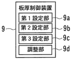
- the plate thickness control device 9 includes a first setting unit 9a, a second setting unit 9b, a third setting unit 9c, and an adjusting unit 9d.
- the first setting unit 9a is configured to roll the roll in the rolling mill 1 based on the first deviation ⁇ H (mm) between the measured value H res of the thickness of the rolled material 10 on the entry side of the rolling mill 1 and the reference value H n (mm).
- a reference value ⁇ S FF ref for the first change amount of the gap is set.
- the second setting unit 9b uses the measured value H res of the thickness of the rolled material 10 on the entry side of the rolling mill 1 and the measured value v in res of the speed and the measured value v out res of the speed on the exit side of the rolling mill 1.
- An estimated value h res (mm) of the thickness of the rolled material 10 on the exit side of the rolled material 10 is calculated.
- the second setting unit 9b sets the reference value ⁇ S MF ref of the second change amount of the roll gap in the rolling mill 1 based on the second deviation ⁇ h (mm) between the estimated value h res and the reference value h n (mm). To do.
- the third setting unit 9c is based on the first change amount reference value ⁇ S FF ref set by the first setting unit 9a and the second change amount reference value ⁇ S MF ref set by the second setting unit 9b.
- the operation amount of the roll gap in the rolling mill 1 is set.
- the adjusting unit 9d automatically and sequentially adjusts the gain of the first setting unit 9a based on the comparison result between the first deviation on the entry side of the rolling mill 1 and the second deviation on the exit side of the rolling mill 1.
- FIG. 3 is a hardware configuration diagram of the rolled material thickness control apparatus according to Embodiment 1 of the present invention.
- the plate thickness control device 9 includes a processing circuit 11.
- the processing circuit 11 includes a processor 11a and a memory 11b.
- the operation of each part of the plate thickness control device 9 in FIG. 2 is realized by at least one processor 11a executing a program stored in at least one memory 11b.
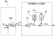
- FIG. 4 is a block diagram of the first setting unit of the sheet thickness control apparatus for rolled material according to Embodiment 1 of the present invention.
- the first setting unit 9a includes a feedforward AGC controller 12a.
- the transfer function C FF of the feedforward AGC controller 12a is set to K P_FF.
- the output part of the feedforward AGC controller 12 a is connected to the input part of the hydraulic pressure reduction position control system 13.
- the hydraulic pressure reduction position control system 13 includes a servo valve of the reduction device 5 and a hydraulic piping system.
- the transfer function of the hydraulic pressure reduction position control system 13 is represented by Gp.
- the output part of the hydraulic pressure reduction position control system 13 is connected to the input part of the first conversion block 14.
- the output unit of the first conversion block 14 is connected to the input unit of the second conversion block 15.
- the first deviation ⁇ H of the thickness of the rolled material 10 is expressed by the following equation (1).
- the first deviation ⁇ H is input to the feedforward AGC controller 12a.
- the feedforward AGC controller 12a calculates a reference value ⁇ S FF ref of the first change amount of the roll gap.
- the reference value ⁇ S FF ref is calculated so that the direction in which the space between the upper work roll 2 and the lower work roll 3 is narrow is negative.
- the hydraulic pressure reduction position control system 13 changes the distance between the upper work roll 2 and the lower work roll 3 based on the reference value ⁇ S FF ref .
- the first conversion block 14 converts the change amount ⁇ S FF (mm) of the distance between the upper work roll 2 and the lower work roll 3 into the change amount ⁇ P FF (kN) of the rolling load.
- the amount of change ⁇ P FF in the rolling load is expressed by the following equation (2).
- M is a mill constant (kN / mm) representing mill elongation due to rolling load.
- Q is a plastic coefficient (kN / mm) representing a change in thickness due to a rolling load.
- the second conversion block 15 converts the rolling load change amount ⁇ P FF into a mill elongation change amount ⁇ P FF / M.
- FIG. 5 is a block diagram of the second setting unit of the sheet thickness control apparatus for rolled material according to Embodiment 1 of the present invention.
- the second setting unit 9b includes an estimator 12b and a mass flow AGC controller 12c.
- the output unit of the estimator 12b is connected to the input unit of the mass flow AGC controller 12c.
- the transfer coefficient C MF of the mass flow AGC controller 12c is set to K P_MF + K I_MF / s.
- s is a Laplace operator.
- the output part of the mass flow AGC controller 12 c is connected to the input part of the hydraulic pressure reduction position control system 13.
- the hydraulic pressure reduction position control system 13 includes a servo valve of the reduction device 5 and a hydraulic piping system.
- the transfer function of the hydraulic pressure reduction position control system 13 is represented by Gp.
- the output part of the hydraulic pressure reduction position control system 13 is connected to the input part of the first conversion block 14.
- the output unit of the first conversion block 14 is connected to the input unit of the second conversion block 15.
- the estimator 12b calculates the estimated value h res of the thickness of the rolled material 10 on the exit side of the rolling mill 1 on the constant mass flow side. Specifically, the estimated value h res is expressed by the following equation (4).
- the second deviation ⁇ h of the thickness of the rolled material 10 is expressed by the following equation (5).
- the second deviation ⁇ h is input to the mass flow AGC controller 12c.
- the mass flow AGC controller 12c calculates the reference value ⁇ S MF ref of the second change amount of the roll gap.
- the reference value ⁇ S MF ref is calculated so that the direction in which the space between the upper work roll 2 and the lower work roll 3 is narrow is negative.
- the hydraulic pressure reduction position control system 13 changes the distance between the upper work roll 2 and the lower work roll 3 based on the reference value ⁇ S MF ref .
- the first conversion block 14 converts the change amount ⁇ S MF (mm) of the distance between the upper work roll 2 and the lower work roll 3 into the change amount ⁇ P MF (kN) of the rolling load.
- the rolling load change amount ⁇ P MF is expressed by the following equation (6).
- M is a mill constant (kN / mm) representing mill elongation due to rolling load.
- Q is a plastic coefficient (kN / mm) representing a change in thickness due to a rolling load.
- the second conversion block 15 converts the rolling load change ⁇ P MF into the mill elongation change ⁇ P MF / M.
- FIG. 6 is a flowchart for explaining the operation of the rolled material thickness control apparatus according to Embodiment 1 of the present invention.
- step S1 the adjusting unit 9d determines whether the product of the first deviation ⁇ H and the second deviation ⁇ h is zero.
- step S1 If the product of the first deviation ⁇ H and the second deviation ⁇ h is 0 in step S1, the process proceeds to step S2. In step S2, the gain adjustment amount ⁇ Kp of the first setting unit 9a is set to zero. Thereafter, the operation ends.
- step S3 the adjustment unit 9d determines whether the positive and negative signs of the first deviation ⁇ H and the second deviation ⁇ h are the same. Specifically, the adjustment unit 9d determines whether or not the product of the first deviation ⁇ H and the second deviation ⁇ h is greater than zero.
- step S3 If the positive and negative signs of the first deviation ⁇ H and the second deviation ⁇ h are the same in step S3, the product of the first deviation ⁇ H and the second deviation ⁇ h is greater than zero. In this case, the process proceeds to step S4.
- step S4 the adjustment unit 9d sets the gain adjustment amount ⁇ Kp of the first setting unit 9a to a value larger than zero. Thereafter, the operation ends.
- step S3 When the positive and negative signs of the first deviation ⁇ H and the second deviation ⁇ h are different in step S3, the product of the first deviation ⁇ H and the second deviation ⁇ h becomes smaller than zero. In this case, the process proceeds to step S5.
- step S5 the adjustment unit 9d sets the gain adjustment amount ⁇ Kp of the first setting unit 9a to a value smaller than zero. Thereafter, the operation ends.
- FIG. 7 is a diagram showing a simulation result of the control by the rolled thickness control device in Embodiment 1 of the present invention.
- FIG. 7 is a diagram showing the line speed.
- the line speed is the peripheral speed between the upper work roll 2 and the lower work roll 3.
- the second diagram from the top in FIG. 7 is a diagram showing the tension applied to the rolled material 10 on the entry side and the exit side of the rolling mill 1.
- 7 is a diagram showing the thickness of the rolled material 10 on the entry side and the exit side of the rolling mill 1.
- the lowermost diagram in FIG. 7 is a diagram showing the rolling load.
- the target value of the line speed is 100 (mpm).
- the target value of the tension applied to the rolled material 10 on the entry side and the exit side of the rolling mill 1 is 100 (MPa).
- the average value of the actual measurement values H res of the thickness of the rolled material 10 on the entry side of the rolling mill 1 is 2.69 (mm).
- the target value (reference value) h n of the thickness of the rolled material 10 on the exit side of the rolling mill 1 is 2.228 (mm). At this time, the rolling reduction of the rolling mill 1 is 17.2%.
- the actual measurement value H res of the thickness of the rolled material 10 varies.
- the fluctuation corresponds to a sin wave.
- the amplitude of the fluctuation is 0.0015 (mm).
- the stall tension is applied to the rolled material 10 until the time T reaches 2 (s).
- the stall tension is set to 40% of the target value. Thereafter, the rolling of the rolled material 10 is started by increasing the line speed.
- the plate thickness control device 9 starts to control the thickness of the rolled material 10.
- the actual measurement value h res of the thickness of the rolled material 10 on the exit side of the rolling mill 1 is repeatedly fluctuated.
- the plate thickness control device 9 adjusts the gain of the first setting unit 9a along the flow of FIG. For example, when the number of times the actual measurement value h res reaches the target value h n is 6, the plate thickness control device 9 adjusts the gain of the first setting unit 9a along the flow of FIG.
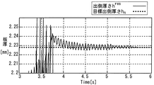
- FIG. 8 is an enlarged view showing a simulation result in the case where the gain of the first setting unit is not adjusted by the adjustment unit of the rolled material thickness control apparatus according to Embodiment 1 of the present invention.
- FIG. 9 is an enlarged view showing a simulation result in the case where the gain of the first setting unit is adjusted by the adjusting unit of the rolled material thickness control apparatus according to Embodiment 1 of the present invention.
- the actual measurement value h res of the thickness of the rolled material 10 on the exit side of the rolling mill 1 repeatedly fluctuates with reference to the target value h n . Such fluctuations do not converge.
- the adjustment unit 9d starts adjusting the gain of the first setting unit 9a.
- the measured value h res of the thickness of the rolled material 10 on the exit side of the rolling mill 1 repeats fluctuations with the target value h n as a reference. The fluctuation converges.
- the gain of the 1st setting part 9a is based on the comparison result of 1st deviation (DELTA) H in the entrance side of the rolling mill 1, and 2nd deviation (DELTA) h in the exit side of the rolling mill 1.
- the gain of the first setting unit 9a is optimized. For this reason, the precision of the thickness of the rolling material 10 in the exit side of the rolling mill 1 can be improved.
- the adjusting unit 9d increases the gain of the first setting unit 9a, and the positive and negative signs of the first deviation ⁇ H and the second deviation ⁇ h. If they are different, the gain of the first setting unit 9a is reduced. For this reason, the precision of the thickness of the rolling material 10 in the exit side of the rolling mill 1 can be improved by simple control.
- the adjustment of the gain of the first setting unit 9a by the adjusting unit 9d may not be performed. In this case, the influence of the error of the estimated value h res due to the constant mass flow side can be removed.
- the influence of the measurement noise of the entrance side plate speed meter 6, the entrance side plate thickness meter 7, and the exit side plate speed meter 8 can be removed.
- the rolled material thickness control apparatus can be used in a system that increases the accuracy of the thickness of the rolled material on the exit side of the rolling mill.
Landscapes
- Engineering & Computer Science (AREA)
- Mechanical Engineering (AREA)
- Control Of Metal Rolling (AREA)
Abstract
Description
図1はこの発明の実施の形態1における圧延材の板厚制御装置が適用された圧延システムである。
図2はこの発明の実施の形態1における圧延材の板厚制御装置のブロック図である。
図3はこの発明の実施の形態1における圧延材の板厚制御装置のハードウェア構成図である。
図4はこの発明の実施の形態1における圧延材の板厚制御装置の第1設定部のブロック線図である。


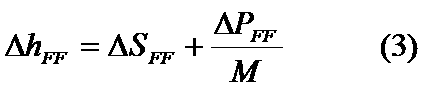
図5はこの発明の実施の形態1における圧延材の板厚制御装置の第2設定部のブロック線図である。



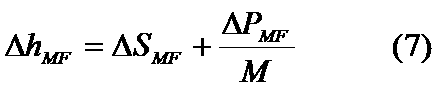
図6はこの発明の実施の形態1における圧延材の板厚制御装置の動作を説明するためのフローチャートである。
図7はこの発明の実施の形態1における圧延材の板厚制御装置による制御のシミュレーション結果を示す図である。
図8はこの発明の実施の形態1における圧延材の板厚制御装置の調整部により第1設定部のゲインを調整しない場合のシミュレーション結果を示す拡大図である。図9はこの発明の実施の形態1における圧延材の板厚制御装置の調整部により第1設定部のゲインを調整する場合のシミュレーション結果を示す拡大図である。
Claims (3)
- 圧延機の入側における圧延材の厚さの実測値と基準値との第1偏差に基づいて前記圧延機におけるロールギャップの第1変化量を設定する第1設定部と、
前記圧延機の入側における圧延材の厚さの実測値と速度の実測値と前記圧延機の出側における圧延材の速度の実測値とにより算出される前記圧延機の出側における圧延材の厚さの推定値と基準値との第2偏差に基づいて前記圧延機におけるロールギャップの第2変化量を設定する第2設定部と、
前記第1設定部により設定された第1変化量と前記第2設定部により設定された第2変化量とに基づいて前記圧延機におけるロールギャップの操作量を設定する第3設定部と、
前記圧延機の入側における第1偏差と前記圧延機の出側における第2偏差との比較結果に基づいて前記第1設定部のゲインを調整する調整部と、
を備えた圧延材の板厚制御装置。 - 前記調整部は、前記第1偏差と前記第2偏差との正負の符号が同じ場合は前記第1設定部のゲインを大きくし、前記第1偏差と前記第2偏差との正負の符号が異なる場合は前記第1設定部のゲインを小さくする請求項1に記載の圧延材の板厚制御装置。
- 前記調整部は、前記第1偏差と前記第2偏差との積の絶対値が予め設定された閾値よりも小さい場合は、前記第1設定部のゲインを調整しない請求項1または請求項2に記載の圧延材の板厚制御装置。
Priority Applications (5)
| Application Number | Priority Date | Filing Date | Title |
|---|---|---|---|
| PCT/JP2015/059434 WO2016151855A1 (ja) | 2015-03-26 | 2015-03-26 | 圧延材の板厚制御装置 |
| JP2017507294A JP6380650B2 (ja) | 2015-03-26 | 2015-03-26 | 圧延材の板厚制御装置 |
| KR1020177013661A KR101942673B1 (ko) | 2015-03-26 | 2015-03-26 | 압연재의 판 두께 제어 장치 |
| CN201580059705.3A CN107073536B (zh) | 2015-03-26 | 2015-03-26 | 轧制件的板厚控制装置 |
| TW104118577A TWI579066B (zh) | 2015-03-26 | 2015-06-09 | 軋延材之板厚控制裝置 |
Applications Claiming Priority (1)
| Application Number | Priority Date | Filing Date | Title |
|---|---|---|---|
| PCT/JP2015/059434 WO2016151855A1 (ja) | 2015-03-26 | 2015-03-26 | 圧延材の板厚制御装置 |
Publications (1)
| Publication Number | Publication Date |
|---|---|
| WO2016151855A1 true WO2016151855A1 (ja) | 2016-09-29 |
Family
ID=56977906
Family Applications (1)
| Application Number | Title | Priority Date | Filing Date |
|---|---|---|---|
| PCT/JP2015/059434 Ceased WO2016151855A1 (ja) | 2015-03-26 | 2015-03-26 | 圧延材の板厚制御装置 |
Country Status (5)
| Country | Link |
|---|---|
| JP (1) | JP6380650B2 (ja) |
| KR (1) | KR101942673B1 (ja) |
| CN (1) | CN107073536B (ja) |
| TW (1) | TWI579066B (ja) |
| WO (1) | WO2016151855A1 (ja) |
Cited By (5)
| Publication number | Priority date | Publication date | Assignee | Title |
|---|---|---|---|---|
| CN111375637A (zh) * | 2018-12-28 | 2020-07-07 | 株式会社日立制作所 | 轧制控制装置、轧制控制方法、以及轧制控制程序 |
| EP3936248A1 (de) * | 2020-07-07 | 2022-01-12 | Primetals Technologies Germany GmbH | Walzen unter berücksichtigung von frequenzverhalten |
| EP3974073A1 (de) * | 2020-09-28 | 2022-03-30 | Primetals Technologies Germany GmbH | Walzen unter berücksichtigung von frequenzverhalten |
| JP2023549732A (ja) * | 2021-09-28 | 2023-11-29 | 寧徳時代新能源科技股▲分▼有限公司 | 冷間プレス機の圧力制御方法及び電子機器 |
| WO2025062852A1 (ja) * | 2023-09-21 | 2025-03-27 | Jx金属株式会社 | チタン銅箔、チタン銅条、電子部品及び、チタン銅箔の製造方法 |
Families Citing this family (4)
| Publication number | Priority date | Publication date | Assignee | Title |
|---|---|---|---|---|
| JP6780786B2 (ja) * | 2017-09-13 | 2020-11-04 | 東芝三菱電機産業システム株式会社 | 圧延ラインの数学モデル算出装置および制御装置 |
| KR102297062B1 (ko) * | 2019-06-14 | 2021-09-03 | 도시바 미쓰비시덴키 산교시스템 가부시키가이샤 | 판 두께 제어 장치 및 판 두께 제어 방법 |
| JP7137549B2 (ja) * | 2019-11-14 | 2022-09-14 | 株式会社日立製作所 | プラント制御装置およびプラント制御方法 |
| KR102832935B1 (ko) * | 2021-03-23 | 2025-07-10 | 가부시키가이샤 티마이크 | 연속식 압연기의 사행 제어 장치 |
Citations (4)
| Publication number | Priority date | Publication date | Assignee | Title |
|---|---|---|---|---|
| JPS54128966A (en) * | 1978-03-31 | 1979-10-05 | Hitachi Ltd | Method and apparatus for automatic control of sheet gauge in rolling mill |
| JPS62259609A (ja) * | 1986-05-02 | 1987-11-12 | Sumitomo Metal Ind Ltd | 圧延機の板厚制御ゲイン自動調整方法 |
| JPH10211512A (ja) * | 1997-01-28 | 1998-08-11 | Sumitomo Metal Ind Ltd | 被圧延材の厚さ制御方法及びその装置 |
| JP2002172406A (ja) * | 2000-12-06 | 2002-06-18 | Mitsubishi Heavy Ind Ltd | 圧延機の板厚補正方法 |
Family Cites Families (18)
| Publication number | Priority date | Publication date | Assignee | Title |
|---|---|---|---|---|
| JPH0531516A (ja) * | 1991-01-19 | 1993-02-09 | Kobe Steel Ltd | 圧延機の自動板厚制御装置 |
| US6401506B1 (en) * | 1998-02-27 | 2002-06-11 | Nippon Steel Corporation | Sheet rolling method and sheet rolling mill |
| JP2001225102A (ja) * | 2000-02-15 | 2001-08-21 | Daido Steel Co Ltd | 自動板厚制御システムを備えた圧延機及びそのシステムを使用した圧延方法 |
| JP2003170210A (ja) * | 2001-12-06 | 2003-06-17 | Yaskawa Electric Corp | 冷間圧延機の自動板厚制御方法 |
| JP4268582B2 (ja) * | 2004-10-14 | 2009-05-27 | 新日本製鐵株式会社 | 板厚制御方法及び板厚・形状非干渉制御方法 |
| JP4824388B2 (ja) * | 2005-10-28 | 2011-11-30 | 株式会社神戸製鋼所 | 圧延制御装置及び圧延制御方法 |
| JP2007253223A (ja) * | 2006-03-24 | 2007-10-04 | Kobe Steel Ltd | 圧延機の板厚制御方法および圧延装置 |
| JP2006212709A (ja) * | 2006-04-27 | 2006-08-17 | Hitachi Ltd | 圧延設備の制御方法 |
| JP2007090437A (ja) * | 2007-01-09 | 2007-04-12 | Toshiba Mitsubishi-Electric Industrial System Corp | リバース式圧延機における板厚制御装置 |
| CN101116874A (zh) * | 2007-06-15 | 2008-02-06 | 中国第一重型机械集团公司 | 可逆冷轧机流量agc带材厚度控制方法 |
| CN101795786B (zh) * | 2007-09-20 | 2012-09-26 | 东芝三菱电机产业系统株式会社 | 板厚控制装置 |
| AU2008319728B2 (en) * | 2007-11-02 | 2011-08-11 | Nippon Steel Corporation | Strip rolling mill and its control method |
| CN101844155B (zh) * | 2009-12-29 | 2011-08-31 | 中冶南方(武汉)自动化有限公司 | 一种轧机agc控制方法 |
| US8973419B2 (en) * | 2010-04-13 | 2015-03-10 | Nippon Steel & Sumitomo Metal Corporation | Rolling mill and method of zero adjustment of rolling mill |
| CN102274863B (zh) * | 2011-06-07 | 2013-04-17 | 中冶赛迪工程技术股份有限公司 | 具有pi参数限制的单机架轧机自动板厚控制方法 |
| JP5734112B2 (ja) * | 2011-06-24 | 2015-06-10 | 株式会社神戸製鋼所 | 圧延機での板厚制御方法 |
| CN102764771B (zh) * | 2012-07-31 | 2014-09-10 | 中冶赛迪电气技术有限公司 | 一种基于秒流量的单机架可逆轧机板厚自适应控制方法 |
| CN103934278B (zh) * | 2013-01-23 | 2015-10-28 | 宝山钢铁股份有限公司 | 一种热轧精轧带钢厚度控制方法 |
-
2015
- 2015-03-26 WO PCT/JP2015/059434 patent/WO2016151855A1/ja not_active Ceased
- 2015-03-26 KR KR1020177013661A patent/KR101942673B1/ko active Active
- 2015-03-26 CN CN201580059705.3A patent/CN107073536B/zh active Active
- 2015-03-26 JP JP2017507294A patent/JP6380650B2/ja active Active
- 2015-06-09 TW TW104118577A patent/TWI579066B/zh active
Patent Citations (4)
| Publication number | Priority date | Publication date | Assignee | Title |
|---|---|---|---|---|
| JPS54128966A (en) * | 1978-03-31 | 1979-10-05 | Hitachi Ltd | Method and apparatus for automatic control of sheet gauge in rolling mill |
| JPS62259609A (ja) * | 1986-05-02 | 1987-11-12 | Sumitomo Metal Ind Ltd | 圧延機の板厚制御ゲイン自動調整方法 |
| JPH10211512A (ja) * | 1997-01-28 | 1998-08-11 | Sumitomo Metal Ind Ltd | 被圧延材の厚さ制御方法及びその装置 |
| JP2002172406A (ja) * | 2000-12-06 | 2002-06-18 | Mitsubishi Heavy Ind Ltd | 圧延機の板厚補正方法 |
Cited By (11)
| Publication number | Priority date | Publication date | Assignee | Title |
|---|---|---|---|---|
| CN111375637A (zh) * | 2018-12-28 | 2020-07-07 | 株式会社日立制作所 | 轧制控制装置、轧制控制方法、以及轧制控制程序 |
| CN111375637B (zh) * | 2018-12-28 | 2022-03-18 | 株式会社日立制作所 | 轧制控制装置、轧制控制方法、以及存储介质 |
| EP3936248A1 (de) * | 2020-07-07 | 2022-01-12 | Primetals Technologies Germany GmbH | Walzen unter berücksichtigung von frequenzverhalten |
| WO2022008133A1 (de) * | 2020-07-07 | 2022-01-13 | Primetals Technologies Germany Gmbh | Walzen unter berücksichtigung von frequenzverhalten |
| EP3936248B1 (de) | 2020-07-07 | 2023-10-25 | Primetals Technologies Germany GmbH | Walzen unter berücksichtigung von frequenzverhalten |
| US12459019B2 (en) | 2020-07-07 | 2025-11-04 | Primetals Technologies Germany Gmbh | Rolling taking frequency behavior into account |
| EP3974073A1 (de) * | 2020-09-28 | 2022-03-30 | Primetals Technologies Germany GmbH | Walzen unter berücksichtigung von frequenzverhalten |
| EP3974073B1 (de) | 2020-09-28 | 2023-07-19 | Primetals Technologies Germany GmbH | Walzen unter berücksichtigung von frequenzverhalten |
| JP2023549732A (ja) * | 2021-09-28 | 2023-11-29 | 寧徳時代新能源科技股▲分▼有限公司 | 冷間プレス機の圧力制御方法及び電子機器 |
| JP7514396B2 (ja) | 2021-09-28 | 2024-07-10 | 寧徳時代新能源科技股▲分▼有限公司 | 冷間プレス機の圧力制御方法及び電子機器 |
| WO2025062852A1 (ja) * | 2023-09-21 | 2025-03-27 | Jx金属株式会社 | チタン銅箔、チタン銅条、電子部品及び、チタン銅箔の製造方法 |
Also Published As
| Publication number | Publication date |
|---|---|
| JP6380650B2 (ja) | 2018-08-29 |
| TW201634140A (zh) | 2016-10-01 |
| KR20170073642A (ko) | 2017-06-28 |
| CN107073536A (zh) | 2017-08-18 |
| TWI579066B (zh) | 2017-04-21 |
| CN107073536B (zh) | 2019-11-05 |
| JPWO2016151855A1 (ja) | 2017-06-29 |
| KR101942673B1 (ko) | 2019-01-25 |
Similar Documents
| Publication | Publication Date | Title |
|---|---|---|
| JP6380650B2 (ja) | 圧延材の板厚制御装置 | |
| AU2015219814B2 (en) | Control Device for Machine Apparatus and Gain Determination Method for Friction Compensation | |
| JP6627740B2 (ja) | タンデム冷間圧延機の板厚制御装置 | |
| JP6094494B2 (ja) | 圧延材の板厚制御装置 | |
| DE102018209093A1 (de) | Motorsteuereinheit | |
| KR101176322B1 (ko) | 압연 제어 장치, 압연 제어 방법 및 압연기의 피드포워드 판두께 제어 방법 | |
| CN108607903B (zh) | 金属板材辊轧弯曲成形回弹补偿机构 | |
| CN110730695B (zh) | 轧制生产线的数学模型计算装置及控制装置 | |
| JP6478890B2 (ja) | 蛇行制御装置、圧延システムおよび蛇行制御方法 | |
| US20100242566A1 (en) | Method for a operating a rolling mill train with curvature recognition | |
| JP6206422B2 (ja) | 鋼板の形状矯正装置および形状矯正方法 | |
| JP6625500B2 (ja) | 圧延機の制御装置、圧延機の制御方法、および制御プログラム | |
| JP6436120B2 (ja) | 金属帯の通板位置制御方法および装置 | |
| CN112792138A (zh) | 工厂设备控制装置和工厂设备控制方法 | |
| JP2017185505A (ja) | 圧延機の制御方法 | |
| JP6299641B2 (ja) | ブライドルロールの張力制御方法および装置 | |
| JP2014030837A (ja) | 圧延機の板厚制御方法 | |
| JP6332191B2 (ja) | 調質圧延装置及び調質圧延方法 | |
| CN111299330A (zh) | 轧制生产线的数学模型计算装置及控制装置 | |
| JP7495642B2 (ja) | 圧延制御装置、圧延制御方法、およびプログラム | |
| KR100851201B1 (ko) | 핀치롤에서의 사행 제어 방법 | |
| US20170341117A1 (en) | Plate width control device for material to be rolled | |
| JP2018103197A (ja) | 圧延機の板厚制御装置および該方法ならびに圧延機 | |
| JP2018027553A (ja) | 圧延機の板厚制御方法および装置 | |
| CN117098614A (zh) | 串列式轧制系统 |
Legal Events
| Date | Code | Title | Description |
|---|---|---|---|
| 121 | Ep: the epo has been informed by wipo that ep was designated in this application |
Ref document number: 15886407 Country of ref document: EP Kind code of ref document: A1 |
|
| ENP | Entry into the national phase |
Ref document number: 2017507294 Country of ref document: JP Kind code of ref document: A |
|
| ENP | Entry into the national phase |
Ref document number: 20177013661 Country of ref document: KR Kind code of ref document: A |
|
| NENP | Non-entry into the national phase |
Ref country code: DE |
|
| 122 | Ep: pct application non-entry in european phase |
Ref document number: 15886407 Country of ref document: EP Kind code of ref document: A1 |