WO2016147605A1 - 金属製部材の腐食低減方法 - Google Patents
金属製部材の腐食低減方法 Download PDFInfo
- Publication number
- WO2016147605A1 WO2016147605A1 PCT/JP2016/001258 JP2016001258W WO2016147605A1 WO 2016147605 A1 WO2016147605 A1 WO 2016147605A1 JP 2016001258 W JP2016001258 W JP 2016001258W WO 2016147605 A1 WO2016147605 A1 WO 2016147605A1
- Authority
- WO
- WIPO (PCT)
- Prior art keywords
- gas
- metal member
- corrosion
- corrosive
- contact
- Prior art date
- Legal status (The legal status is an assumption and is not a legal conclusion. Google has not performed a legal analysis and makes no representation as to the accuracy of the status listed.)
- Ceased
Links
Images
Classifications
-
- C—CHEMISTRY; METALLURGY
- C23—COATING METALLIC MATERIAL; COATING MATERIAL WITH METALLIC MATERIAL; CHEMICAL SURFACE TREATMENT; DIFFUSION TREATMENT OF METALLIC MATERIAL; COATING BY VACUUM EVAPORATION, BY SPUTTERING, BY ION IMPLANTATION OR BY CHEMICAL VAPOUR DEPOSITION, IN GENERAL; INHIBITING CORROSION OF METALLIC MATERIAL OR INCRUSTATION IN GENERAL
- C23F—NON-MECHANICAL REMOVAL OF METALLIC MATERIAL FROM SURFACE; INHIBITING CORROSION OF METALLIC MATERIAL OR INCRUSTATION IN GENERAL; MULTI-STEP PROCESSES FOR SURFACE TREATMENT OF METALLIC MATERIAL INVOLVING AT LEAST ONE PROCESS PROVIDED FOR IN CLASS C23 AND AT LEAST ONE PROCESS COVERED BY SUBCLASS C21D OR C22F OR CLASS C25
- C23F15/00—Other methods of preventing corrosion or incrustation
Definitions
- the present invention relates to a method for reducing corrosion of a metal member.
- the corrosive gas adsorbed on the surface of the metal member at the time of contact is desorbed.
- the method disclosed in Patent Document 1 has a problem of high cost because a large heating device is required when the size of the pipe is large.
- temperature unevenness may occur in the piping.
- the present invention solves the above-mentioned problems of the prior art, and allows the corrosive gas adsorbed on the surface of the metal member at the time of contact to be desorbed sufficiently and reliably at a low cost, thereby making the metal member It is an object of the present invention to provide a method for reducing corrosion of steel.
- a method for reducing corrosion of a metal member due to contact with a corrosive gas wherein a preheated desorption gas is brought into contact with a contact surface of the metal member which is in contact with the corrosive gas. And reducing the corrosion of the metallic member, comprising desorbing the corrosive gas adsorbed on the contact surface.
- the corrosive gas is hydrogen bromide, hydrogen chloride, hydrogen fluoride, bromine gas, chlorine gas, fluorine gas, boron trichloride, ammonia, hydrogen sulfide, sulfur dioxide, nitrogen monoxide, nitrogen dioxide, selenization.
- the corrosive gas adsorbed on the surface of the metal member at the time of contact can be desorbed sufficiently and reliably at low cost, and the corrosion of the metal member can be reduced.
- the method for reducing corrosion of a metal member according to the present embodiment is a method for reducing corrosion of a metal member due to contact with a corrosive gas. Contacting the heated desorption gas to desorb the corrosive gas adsorbed on the contact surface.
- the metal member is not heated directly, but the metal member is heated via the desorption gas. Therefore, if only the facility for heating the desorption gas is provided, the metal member is heated. be able to. Therefore, the corrosive gas can be desorbed by the same operation regardless of the size of the metal member. Therefore, even when the metal member size is large, the corrosive gas can be desorbed at a low cost. Can do. Furthermore, even if there are complicatedly shaped parts (for example, complicatedly complicated parts) in the metal member, the metal member can be heated uniformly with no problem by the heated desorption gas. Even in the case of a manufactured member, it is possible to desorb corrosive gas.
- the temperature of the desorption gas heated in advance can be 30 ° C. or higher and lower than 100 ° C., and preferably 30 ° C. or higher and 80 ° C. or lower. When the temperature is 30 ° C. or more and less than 100 ° C., the corrosive gas can be desorbed without causing the metal member to proceed with corrosion.
- the method for heating the desorption gas is not particularly limited, and any method can be adopted as long as the desorption gas can be heated to a desired temperature in advance before contacting the contact surface of the metal member. May be.
- the temperature of the metal member before contacting the desorption gas can be normal temperature or lower, for example, 25 ° C. or lower, or 20 ° C. or higher and 25 ° C. or lower.
- the kind of corrosive gas is not specifically limited,
- area is mention
- Specific examples include hydrogen bromide (HBr), hydrogen chloride (HCl), hydrogen fluoride (HF), bromine gas (Br 2 ), chlorine gas (Cl 2 ), fluorine gas (F 2 ), boron trichloride ( BCl 3 ), ammonia (NH 3 ), hydrogen sulfide (H 2 S), sulfur dioxide (SO 2 ), nitric oxide (NO), nitrogen dioxide (NO 2 ), hydrogen selenide (H 2 Se), tetrafluoride
- the gas include corrosive compounds such as silicon fluoride (SiF 4 ) and tungsten hexafluoride (WF 6 ).
- N 2 nitrogen gas
- N 2 at least one of the gases of the corrosive compounds, it may be used as a corrosive gas that is mixed with non-corrosive gases such as air.
- the method for reducing corrosion of a metal member according to this embodiment is particularly suitable when a corrosive gas containing hydrogen bromide, which is a bromine compound having a bromine atom in its molecule, is used among various corrosive gases.
- the type of desorption gas is not particularly limited, for example, nitrogen gas (N 2), argon (Ar), helium (the He), hydrogen gas (H 2), carbon dioxide (CO 2), and oxygen
- Non-corrosive gases such as gas (O 2 ) and air can be mentioned.
- These non-corrosive gases may be used alone as a desorption gas, or two or more types may be appropriately mixed to form a desorption gas. However, it is preferable to use a gas having good diffusibility as the desorption gas.
- the type of the metal member is not particularly limited, and examples thereof include a metal member that is used in a corrosive gas production process, a purification process, or a semiconductor production process and comes into contact with the corrosive gas. More specifically, pipes that distribute corrosive gas in the respective steps and metal members provided in various devices (tanks, pumps, compressors, etc.) used in the respective steps.
- the corrosion reduction method for metal members according to the present embodiment is applied to pipes through which corrosive gas has been circulated and various equipment used in each of the above steps, the corrosive gas is removed from the pipes and various equipment. Therefore, even if these pipes and various devices are used for other types of gases, mixing of corrosive gas into other types of gases can be suppressed.
- the type of metal constituting the metal member is not particularly limited.
- pure metal such as iron (Fe), titanium (Ti), tantalum (Ta), stainless steel, carbon steel, nickel alloy And the like. Of these metals, stainless steel is preferred.
- this embodiment shows an example of this invention and this invention is not limited to this embodiment.
- various changes or improvements can be added to the present embodiment, and forms to which such changes or improvements are added can also be included in the present invention.
- the stainless steel electrolytic polishing tube container into which the test piece was inserted was cooled to ⁇ 20 ° C.
- hydrogen bromide gas corrosive gas
- liquid hydrogen bromide containing 1 ppm of water was brought into contact with the test piece.
- the temperature of the hydrogen bromide is raised to 40 ° C.
- the pressure inside the stainless steel electrolytic polishing tube container is set to 3.2 MPa with a gauge pressure
- hydrogen bromide is vaporized
- the test piece is made into hydrogen bromide. Left in gas for 1 day. In this test example, the entire surface of the test piece is the contact surface of the corrosive gas.
- nitrogen gas desorption gas
- the pressure inside the stainless steel electrolytic polishing tube container is adjusted to the gauge pressure.
- the pressure was raised to 1.5 MPa (crushing), and the purging operation consisting of the subsequent blow procedure was repeated 15 times.
- the temperature of the nitrogen gas was 20 ° C, 30 ° C, 40 ° C, 50 ° C, 80 ° C, or 100 ° C.
- the temperature inside the stainless steel electrolytic polishing tube container was constantly measured, and it was confirmed that the nitrogen gas was adjusted to a predetermined temperature.
- the measuring method of the quantity of each ion is as follows. First, a method for measuring the amount of bromide ions will be described. 1 mL of pure water in which the test piece was immersed was collected with a syringe and then injected into an ion chromatograph to quantify bromide ions. Details of the ion chromatograph used are described below.
- Measuring device ion chromatograph manufactured by DIONEX (model: DX-120) Guard column: Dionex IonPac AG23 made by DIONEX Separation column: Dionex IonPac AS23 manufactured by DIONEX Suppressor: Suppressor ASRS-300 manufactured by DIONEX Suppressor current: 50 mA Eluent flow rate: 1.5 mL / min Eluent: 2.7 mmol / L Na 2 CO 3 , 0.3 mmol / L NaHCO 3
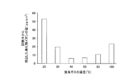
- the amount of bromide ions eluted from the test piece was smaller when the temperature of the nitrogen gas was 30 to 80 ° C. than when the temperature of the nitrogen gas was 20 ° C. Further, when the temperature of the nitrogen gas was 30 to 80 ° C., no corrosion was confirmed on the surface of the test piece after being left for 5 days, whereas when the temperature of the nitrogen gas was 20 ° C., the surface was kept for 5 days. Corrosion was confirmed on the surface of the test piece after being left, and the corrosion progressed during the standing for 5 days.
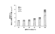
- the amount of metal ions eluted from the test piece is larger than when the temperature of the nitrogen gas is 30 to 80 ° C. You can see that is progressing.
- the temperature of nitrogen gas was 100 degreeC, corrosion was confirmed on the surface of the test piece immediately after taking out the test piece from the stainless steel electrolytic polishing tube container. From this, it can be seen that the corrosion by hydrogen bromide and water remaining on the surface of the test piece was accelerated by nitrogen gas heated to 100 ° C. in advance.
Landscapes
- Chemical & Material Sciences (AREA)
- Engineering & Computer Science (AREA)
- Materials Engineering (AREA)
- Mechanical Engineering (AREA)
- Metallurgy (AREA)
- Organic Chemistry (AREA)
- Preventing Corrosion Or Incrustation Of Metals (AREA)
- Testing Resistance To Weather, Investigating Materials By Mechanical Methods (AREA)
Abstract
Description
しかしながら、特許文献1に開示の方法では、配管のサイズが大きいと大型の加熱装置が必要となるため、高コストであるという問題があった。また、複雑な形状の部分では、加熱自体が困難であるという問題があった。さらに、特許文献1に開示の方法では、配管に温度ムラが生じる場合があった。そのため、局所的に温度が上がりすぎた部分では、腐食性ガス中に水分が含有されている場合は脱着よりもむしろ腐食性ガスによる腐食が進むおそれがあり、局所的に温度が低い部分では腐食性ガスを十分に脱着することができないおそれがあった。
[1] 腐食性ガスの接触による金属製部材の腐食を低減する方法であって、前記金属製部材の表面のうち前記腐食性ガスが接触した接触面に、予め加熱された脱着用ガスを接触させて、前記接触面に吸着された前記腐食性ガスを脱着させることを含む金属製部材の腐食低減方法。
[3] 前記腐食性ガスが、臭化水素、塩化水素、フッ化水素、臭素ガス、塩素ガス、フッ素ガス、三塩化ホウ素、アンモニア、硫化水素、二酸化硫黄、一酸化窒素、二酸化窒素、セレン化水素、四フッ化ケイ素、及び六フッ化タングステンのうちの少なくとも1種を含有する[1]又は[2]に記載の金属製部材の腐食低減方法。
[5] 前記金属製部材の金属がステンレス鋼である[1]~[4]のいずれか一項に記載の金属製部材の腐食低減方法。
本実施形態の金属製部材の腐食低減方法は、腐食性ガスの接触による金属製部材の腐食を低減する方法であって、金属製部材の表面のうち腐食性ガスが接触した接触面に、予め加熱された脱着用ガスを接触させて、接触面に吸着された腐食性ガスを脱着させることを含む。
脱着用ガスを加熱する方法は特に限定されるものではなく、金属製部材の接触面に接触させる前に脱着用ガスを予め所望の温度に加熱することができるならば、どのような方法を採用してもよい。
なお、脱着用ガスを接触させる前の金属製部材の温度は、常温以下とすることができ、例えば25℃以下としてもよいし、20℃以上25℃以下としてもよい。
さらに、脱着用ガスの種類は特に限定されるものではなく、例えば、窒素ガス(N2)、アルゴン(Ar)、ヘリウム(He)、水素ガス(H2)、二酸化炭素(CO2)、酸素ガス(O2)、空気等の非腐食性ガスがあげられる。これらの非腐食性ガスは、1種類を単独で脱着用ガスとしてもよいし、2種以上を適宜混合して脱着用ガスとしてもよい。ただし、脱着用ガスとして、拡散性が良好であるものを用いることが好ましい。
なお、腐食性ガスを流通した配管や、前記各工程において使用された各種機器に対して、本実施形態の金属製部材の腐食低減方法を実施すれば、配管や各種機器から腐食性ガスを除去することができるので、これら配管や各種機器を他種のガスに対して使用したとしても、他種のガスへの腐食性ガスの混入を抑制することができる。
なお、本実施形態は本発明の一例を示したものであって、本発明は本実施形態に限定されるものではない。また、本実施形態には種々の変更又は改良を加えることが可能であり、その様な変更又は改良を加えた形態も本発明に含まれ得る。
ステンレス(SUS316L)製電解研磨管容器の内部にステンレス(SUS316L)製の板状試験片(縦2cm、横5cm、厚さ0.2cm)を挿入した後に、ステンレス製電解研磨管容器の内部に窒素ガスを1時間流通させて、ステンレス製電解研磨管容器の内部及び試験片に付着の水分を除去した。なお、試験片は、表面を研磨度400番相当に研磨したものを用いた。
また、15回のパージ操作が終了してから60分後にステンレス電解研磨管容器の内部の温度が20℃に調整されていることを確認したら、ステンレス電解研磨管容器から試験片を取り出し、20℃の純水に30分間浸漬させた。そして、純水を分析して、試験片から溶出した臭化物イオンの量と、金属イオン(鉄イオン、クロムイオン、及びニッケルイオン)の量を測定した。なお、1種の金属について異なる価数のイオンが存在する場合には、全ての価数のイオンの量を測定し、合計した。例えば、2価の鉄イオンと3価の鉄イオンが純水中に存在する場合には、両イオンのトータルの量を測定した。結果を、表1及び図1,2のグラフに示す。表1及び図1,2のグラフに示した臭化物イオンの量及び金属イオンの量は、純水中に含有されていた各イオンの量を試験片の表面積で除した値であり、すなわち、単位面積当たりの各イオンの溶出量を示す。

試験片を浸漬させた純水1mLをシリンジで分取後、イオンクロマトグラフに注入し臭化物イオンを定量した。使用したイオンクロマトグラフの詳細を以下に記載する。
測定装置:DIONEX社製イオンクロマトグラフ(型式:DX-120)
ガードカラム:DIONEX社製カラムDionex IonPac AG23
分離カラム:DIONEX社製カラムDionex IonPac AS23
サプレッサー:DIONEX社製サプレッサーASRS-300
サプレッサー電流:50mA
溶離液の流量:1.5mL/min
溶離液:2.7mmol/L Na2CO3、0.3mmol/L NaHCO3
測定装置:株式会社島津製作所製ICP発光分光分析装置(型式:ICPS-8100)
RF出力:1.2kW
試料導入速度:1mL/min
積分時間:50sec.
平均回数:3回
測定元素、波長:Fe 259.940nm
Cr 267.716nm
Ni 231.604nm
なお、上記の試験例では、腐食性ガスを脱着するために予め加熱した脱着用ガスを金属製部材に接触させる方法として、脱着用ガスを圧張りした後にブローする手順からなるパージ操作を複数回繰り返す方法を採用したが、予め加熱した脱着用ガスを圧張りせずに流通させる方法も適用可能である。
Claims (5)
- 腐食性ガスの接触による金属製部材の腐食を低減する方法であって、前記金属製部材の表面のうち前記腐食性ガスが接触した接触面に、予め加熱された脱着用ガスを接触させて、前記接触面に吸着された前記腐食性ガスを脱着させることを含む金属製部材の腐食低減方法。
- 前記予め加熱された脱着用ガスの温度が30℃以上100℃未満である請求項1に記載の金属製部材の腐食低減方法。
- 前記腐食性ガスが、臭化水素、塩化水素、フッ化水素、臭素ガス、塩素ガス、フッ素ガス、三塩化ホウ素、アンモニア、硫化水素、二酸化硫黄、一酸化窒素、二酸化窒素、セレン化水素、四フッ化ケイ素、及び六フッ化タングステンのうちの少なくとも1種を含有する請求項1又は請求項2に記載の金属製部材の腐食低減方法。
- 前記脱着用ガスが、窒素ガス、アルゴン、ヘリウム、水素ガス、二酸化炭素、酸素ガス、及び空気のうちの少なくとも1種である請求項1~3のいずれか一項に記載の金属製部材の腐食低減方法。
- 前記金属製部材の金属がステンレス鋼である請求項1~4のいずれか一項に記載の金属製部材の腐食低減方法。
Priority Applications (3)
| Application Number | Priority Date | Filing Date | Title |
|---|---|---|---|
| KR1020177013274A KR20170067893A (ko) | 2015-03-17 | 2016-03-08 | 금속제 부재의 부식 저감 방법 |
| JP2017506068A JPWO2016147605A1 (ja) | 2015-03-17 | 2016-03-08 | 金属製部材の腐食低減方法 |
| CN201680003826.0A CN107002253A (zh) | 2015-03-17 | 2016-03-08 | 金属制构件的腐蚀降低方法 |
Applications Claiming Priority (2)
| Application Number | Priority Date | Filing Date | Title |
|---|---|---|---|
| JP2015-053332 | 2015-03-17 | ||
| JP2015053332 | 2015-03-17 |
Publications (1)
| Publication Number | Publication Date |
|---|---|
| WO2016147605A1 true WO2016147605A1 (ja) | 2016-09-22 |
Family
ID=56918806
Family Applications (1)
| Application Number | Title | Priority Date | Filing Date |
|---|---|---|---|
| PCT/JP2016/001258 Ceased WO2016147605A1 (ja) | 2015-03-17 | 2016-03-08 | 金属製部材の腐食低減方法 |
Country Status (5)
| Country | Link |
|---|---|
| JP (1) | JPWO2016147605A1 (ja) |
| KR (1) | KR20170067893A (ja) |
| CN (1) | CN107002253A (ja) |
| TW (1) | TWI592517B (ja) |
| WO (1) | WO2016147605A1 (ja) |
Citations (3)
| Publication number | Priority date | Publication date | Assignee | Title |
|---|---|---|---|---|
| JP2000097398A (ja) * | 1998-09-24 | 2000-04-04 | Nippon Sanso Corp | ガス容器の内面処理方法 |
| JP3134116B2 (ja) * | 1999-04-23 | 2001-02-13 | 岩谷産業株式会社 | 腐食性ガス供給系での腐食低減方法 |
| JP2002126502A (ja) * | 2000-10-20 | 2002-05-08 | Mitsubishi Heavy Ind Ltd | 有機ハロゲン化合物分解装置用放電管の気密支持装置 |
Family Cites Families (2)
| Publication number | Priority date | Publication date | Assignee | Title |
|---|---|---|---|---|
| CN100344344C (zh) * | 2005-12-07 | 2007-10-24 | 成都华西化工研究所 | 循环移动床脱除烟道气中so2和nox的工艺 |
| CN101398127A (zh) * | 2007-09-27 | 2009-04-01 | 力晶半导体股份有限公司 | 清除气体供应系统及气体清除方法 |
-
2016
- 2016-03-08 CN CN201680003826.0A patent/CN107002253A/zh active Pending
- 2016-03-08 WO PCT/JP2016/001258 patent/WO2016147605A1/ja not_active Ceased
- 2016-03-08 KR KR1020177013274A patent/KR20170067893A/ko not_active Ceased
- 2016-03-08 JP JP2017506068A patent/JPWO2016147605A1/ja active Pending
- 2016-03-16 TW TW105108094A patent/TWI592517B/zh active
Patent Citations (3)
| Publication number | Priority date | Publication date | Assignee | Title |
|---|---|---|---|---|
| JP2000097398A (ja) * | 1998-09-24 | 2000-04-04 | Nippon Sanso Corp | ガス容器の内面処理方法 |
| JP3134116B2 (ja) * | 1999-04-23 | 2001-02-13 | 岩谷産業株式会社 | 腐食性ガス供給系での腐食低減方法 |
| JP2002126502A (ja) * | 2000-10-20 | 2002-05-08 | Mitsubishi Heavy Ind Ltd | 有機ハロゲン化合物分解装置用放電管の気密支持装置 |
Also Published As
| Publication number | Publication date |
|---|---|
| TW201704540A (zh) | 2017-02-01 |
| TWI592517B (zh) | 2017-07-21 |
| KR20170067893A (ko) | 2017-06-16 |
| JPWO2016147605A1 (ja) | 2017-12-28 |
| CN107002253A (zh) | 2017-08-01 |
Similar Documents
| Publication | Publication Date | Title |
|---|---|---|
| TWI786043B (zh) | 保存容器 | |
| JP5231155B2 (ja) | 液相状態の化合物の精製装置 | |
| TWI670232B (zh) | 氟化合物氣體之純化方法 | |
| CN102203324B (zh) | 用含三价铁离子的酸性酸洗溶液酸洗硅钢的方法 | |
| TWI654139B (zh) | Fluorine gas purification method | |
| WO2019167885A1 (ja) | ステンレス鋼部材及びその製造方法 | |
| JPH0625822A (ja) | ステンレス鋼表面不動態化処理 | |
| JP6845235B2 (ja) | 硫化水素混合物及びその製造方法並びに充填容器 | |
| JP2018107438A (ja) | 金属部材の表面処理方法及び半導体素子の製造方法 | |
| DK200801617A (en) | Downhole equipment removal system | |
| JPWO2016147605A1 (ja) | 金属製部材の腐食低減方法 | |
| JP4744017B2 (ja) | 高純度フッ素ガス中の微量不純物の分析方法 | |
| TW201637740A (zh) | 高壓氣體容器之洗淨方法及高壓氣體容器 | |
| JPH05287496A (ja) | ステンレス鋼部材の表面処理方法 | |
| WO2021182045A1 (ja) | 二酸化硫黄混合物及びその製造方法並びに充填容器 | |
| JP2783128B2 (ja) | クリーンルーム用ステンレス鋼部材およびその製造方法 | |
| JPWO2019188912A1 (ja) | 多結晶シリコンの洗浄方法、製造方法および洗浄装置 | |
| KR102489717B1 (ko) | 저 내부식성 금속 기재를 이용한 고순도 불화수소를 저장하기 위한 용기 및 이의 제조방법 | |
| JPH03215656A (ja) | フッ化不働態膜が形成されたステンレス鋼、その製造方法並びにそのステンレスを用いた装置 | |
| JP6826049B2 (ja) | 塩化水素混合物の製造方法 | |
| US20190271085A1 (en) | Processing method, processing apparatus, and evaluation method of metal member | |
| JP2006522226A (ja) | 輸送中の反応性化合物の劣化を低減する方法 | |
| TWI434725B (zh) | 利用氫氧基化合物和離子交換樹脂吸附以純化氟酸系蝕刻液的處理方法 | |
| JPH0711421A (ja) | 半導体製造装置用ステンレス鋼部材 | |
| TW202602784A (zh) | 經填充酸氟化物之容器的製造方法 |
Legal Events
| Date | Code | Title | Description |
|---|---|---|---|
| 121 | Ep: the epo has been informed by wipo that ep was designated in this application |
Ref document number: 16764438 Country of ref document: EP Kind code of ref document: A1 |
|
| ENP | Entry into the national phase |
Ref document number: 2017506068 Country of ref document: JP Kind code of ref document: A |
|
| ENP | Entry into the national phase |
Ref document number: 20177013274 Country of ref document: KR Kind code of ref document: A |
|
| NENP | Non-entry into the national phase |
Ref country code: DE |
|
| 122 | Ep: pct application non-entry in european phase |
Ref document number: 16764438 Country of ref document: EP Kind code of ref document: A1 |