WO2016136265A1 - 冷媒蒸発器 - Google Patents
冷媒蒸発器 Download PDFInfo
- Publication number
- WO2016136265A1 WO2016136265A1 PCT/JP2016/001022 JP2016001022W WO2016136265A1 WO 2016136265 A1 WO2016136265 A1 WO 2016136265A1 JP 2016001022 W JP2016001022 W JP 2016001022W WO 2016136265 A1 WO2016136265 A1 WO 2016136265A1
- Authority
- WO
- WIPO (PCT)
- Prior art keywords
- tank
- refrigerant
- heat exchange
- leeward
- replacement
- Prior art date
- Legal status (The legal status is an assumption and is not a legal conclusion. Google has not performed a legal analysis and makes no representation as to the accuracy of the status listed.)
- Ceased
Links
Images


Classifications
-
- F—MECHANICAL ENGINEERING; LIGHTING; HEATING; WEAPONS; BLASTING
- F25—REFRIGERATION OR COOLING; COMBINED HEATING AND REFRIGERATION SYSTEMS; HEAT PUMP SYSTEMS; MANUFACTURE OR STORAGE OF ICE; LIQUEFACTION SOLIDIFICATION OF GASES
- F25B—REFRIGERATION MACHINES, PLANTS OR SYSTEMS; COMBINED HEATING AND REFRIGERATION SYSTEMS; HEAT PUMP SYSTEMS
- F25B47/00—Arrangements for preventing or removing deposits or corrosion, not provided for in another subclass
- F25B47/006—Arrangements for preventing or removing deposits or corrosion, not provided for in another subclass for preventing frost
-
- F—MECHANICAL ENGINEERING; LIGHTING; HEATING; WEAPONS; BLASTING
- F25—REFRIGERATION OR COOLING; COMBINED HEATING AND REFRIGERATION SYSTEMS; HEAT PUMP SYSTEMS; MANUFACTURE OR STORAGE OF ICE; LIQUEFACTION SOLIDIFICATION OF GASES
- F25B—REFRIGERATION MACHINES, PLANTS OR SYSTEMS; COMBINED HEATING AND REFRIGERATION SYSTEMS; HEAT PUMP SYSTEMS
- F25B39/00—Evaporators; Condensers
- F25B39/02—Evaporators
-
- F—MECHANICAL ENGINEERING; LIGHTING; HEATING; WEAPONS; BLASTING
- F28—HEAT EXCHANGE IN GENERAL
- F28D—HEAT-EXCHANGE APPARATUS, NOT PROVIDED FOR IN ANOTHER SUBCLASS, IN WHICH THE HEAT-EXCHANGE MEDIA DO NOT COME INTO DIRECT CONTACT
- F28D1/00—Heat-exchange apparatus having stationary conduit assemblies for one heat-exchange medium only, the media being in contact with different sides of the conduit wall, in which the other heat-exchange medium is a large body of fluid, e.g. domestic or motor car radiators
- F28D1/02—Heat-exchange apparatus having stationary conduit assemblies for one heat-exchange medium only, the media being in contact with different sides of the conduit wall, in which the other heat-exchange medium is a large body of fluid, e.g. domestic or motor car radiators with heat-exchange conduits immersed in the body of fluid
- F28D1/04—Heat-exchange apparatus having stationary conduit assemblies for one heat-exchange medium only, the media being in contact with different sides of the conduit wall, in which the other heat-exchange medium is a large body of fluid, e.g. domestic or motor car radiators with heat-exchange conduits immersed in the body of fluid with tubular conduits
- F28D1/0408—Multi-circuit heat exchangers, e.g. integrating different heat exchange sections in the same unit or heat exchangers for more than two fluids
- F28D1/0426—Multi-circuit heat exchangers, e.g. integrating different heat exchange sections in the same unit or heat exchangers for more than two fluids with units having particular arrangement relative to the large body of fluid, e.g. with interleaved units or with adjacent heat exchange units in common air flow or with units extending at an angle to each other or with units arranged around a central element
- F28D1/0452—Combination of units extending one behind the other with units extending one beside or one above the other
-
- F—MECHANICAL ENGINEERING; LIGHTING; HEATING; WEAPONS; BLASTING
- F28—HEAT EXCHANGE IN GENERAL
- F28D—HEAT-EXCHANGE APPARATUS, NOT PROVIDED FOR IN ANOTHER SUBCLASS, IN WHICH THE HEAT-EXCHANGE MEDIA DO NOT COME INTO DIRECT CONTACT
- F28D1/00—Heat-exchange apparatus having stationary conduit assemblies for one heat-exchange medium only, the media being in contact with different sides of the conduit wall, in which the other heat-exchange medium is a large body of fluid, e.g. domestic or motor car radiators
- F28D1/02—Heat-exchange apparatus having stationary conduit assemblies for one heat-exchange medium only, the media being in contact with different sides of the conduit wall, in which the other heat-exchange medium is a large body of fluid, e.g. domestic or motor car radiators with heat-exchange conduits immersed in the body of fluid
- F28D1/04—Heat-exchange apparatus having stationary conduit assemblies for one heat-exchange medium only, the media being in contact with different sides of the conduit wall, in which the other heat-exchange medium is a large body of fluid, e.g. domestic or motor car radiators with heat-exchange conduits immersed in the body of fluid with tubular conduits
- F28D1/053—Heat-exchange apparatus having stationary conduit assemblies for one heat-exchange medium only, the media being in contact with different sides of the conduit wall, in which the other heat-exchange medium is a large body of fluid, e.g. domestic or motor car radiators with heat-exchange conduits immersed in the body of fluid with tubular conduits the conduits being straight
- F28D1/0535—Heat-exchange apparatus having stationary conduit assemblies for one heat-exchange medium only, the media being in contact with different sides of the conduit wall, in which the other heat-exchange medium is a large body of fluid, e.g. domestic or motor car radiators with heat-exchange conduits immersed in the body of fluid with tubular conduits the conduits being straight the conduits having a non-circular cross-section
- F28D1/05366—Assemblies of conduits connected to common headers, e.g. core type radiators
- F28D1/05391—Assemblies of conduits connected to common headers, e.g. core type radiators with multiple rows of conduits or with multi-channel conduits combined with a particular flow pattern, e.g. multi-row multi-stage radiators
-
- F—MECHANICAL ENGINEERING; LIGHTING; HEATING; WEAPONS; BLASTING
- F28—HEAT EXCHANGE IN GENERAL
- F28F—DETAILS OF HEAT-EXCHANGE AND HEAT-TRANSFER APPARATUS, OF GENERAL APPLICATION
- F28F9/00—Casings; Header boxes; Auxiliary supports for elements; Auxiliary members within casings
- F28F9/02—Header boxes; End plates
- F28F9/0202—Header boxes having their inner space divided by partitions
- F28F9/0204—Header boxes having their inner space divided by partitions for elongated header box, e.g. with transversal and longitudinal partitions
-
- F—MECHANICAL ENGINEERING; LIGHTING; HEATING; WEAPONS; BLASTING
- F28—HEAT EXCHANGE IN GENERAL
- F28F—DETAILS OF HEAT-EXCHANGE AND HEAT-TRANSFER APPARATUS, OF GENERAL APPLICATION
- F28F9/00—Casings; Header boxes; Auxiliary supports for elements; Auxiliary members within casings
- F28F9/02—Header boxes; End plates
- F28F9/0243—Header boxes having a circular cross-section
-
- F—MECHANICAL ENGINEERING; LIGHTING; HEATING; WEAPONS; BLASTING
- F28—HEAT EXCHANGE IN GENERAL
- F28F—DETAILS OF HEAT-EXCHANGE AND HEAT-TRANSFER APPARATUS, OF GENERAL APPLICATION
- F28F9/00—Casings; Header boxes; Auxiliary supports for elements; Auxiliary members within casings
- F28F9/02—Header boxes; End plates
- F28F9/026—Header boxes; End plates with static flow control means, e.g. with means for uniformly distributing heat exchange media into conduits
- F28F9/028—Header boxes; End plates with static flow control means, e.g. with means for uniformly distributing heat exchange media into conduits by using inserts for modifying the pattern of flow inside the header box, e.g. by using flow restrictors or permeable bodies or blocks with channels
-
- F—MECHANICAL ENGINEERING; LIGHTING; HEATING; WEAPONS; BLASTING
- F28—HEAT EXCHANGE IN GENERAL
- F28F—DETAILS OF HEAT-EXCHANGE AND HEAT-TRANSFER APPARATUS, OF GENERAL APPLICATION
- F28F9/00—Casings; Header boxes; Auxiliary supports for elements; Auxiliary members within casings
- F28F9/26—Arrangements for connecting different sections of heat-exchange elements, e.g. of radiators
- F28F9/262—Arrangements for connecting different sections of heat-exchange elements, e.g. of radiators for radiators
- F28F9/268—Arrangements for connecting different sections of heat-exchange elements, e.g. of radiators for radiators by permanent joints, e.g. by welding
-
- F—MECHANICAL ENGINEERING; LIGHTING; HEATING; WEAPONS; BLASTING
- F25—REFRIGERATION OR COOLING; COMBINED HEATING AND REFRIGERATION SYSTEMS; HEAT PUMP SYSTEMS; MANUFACTURE OR STORAGE OF ICE; LIQUEFACTION SOLIDIFICATION OF GASES
- F25B—REFRIGERATION MACHINES, PLANTS OR SYSTEMS; COMBINED HEATING AND REFRIGERATION SYSTEMS; HEAT PUMP SYSTEMS
- F25B2500/00—Problems to be solved
- F25B2500/06—Damage
-
- F—MECHANICAL ENGINEERING; LIGHTING; HEATING; WEAPONS; BLASTING
- F28—HEAT EXCHANGE IN GENERAL
- F28D—HEAT-EXCHANGE APPARATUS, NOT PROVIDED FOR IN ANOTHER SUBCLASS, IN WHICH THE HEAT-EXCHANGE MEDIA DO NOT COME INTO DIRECT CONTACT
- F28D21/00—Heat-exchange apparatus not covered by any of the groups F28D1/00 - F28D20/00
- F28D2021/0019—Other heat exchangers for particular applications; Heat exchange systems not otherwise provided for
- F28D2021/0061—Other heat exchangers for particular applications; Heat exchange systems not otherwise provided for for phase-change applications
- F28D2021/0064—Vaporizers, e.g. evaporators
-
- F—MECHANICAL ENGINEERING; LIGHTING; HEATING; WEAPONS; BLASTING
- F28—HEAT EXCHANGE IN GENERAL
- F28F—DETAILS OF HEAT-EXCHANGE AND HEAT-TRANSFER APPARATUS, OF GENERAL APPLICATION
- F28F9/00—Casings; Header boxes; Auxiliary supports for elements; Auxiliary members within casings
- F28F9/02—Header boxes; End plates
- F28F9/0202—Header boxes having their inner space divided by partitions
- F28F9/0204—Header boxes having their inner space divided by partitions for elongated header box, e.g. with transversal and longitudinal partitions
- F28F9/0209—Header boxes having their inner space divided by partitions for elongated header box, e.g. with transversal and longitudinal partitions having only transversal partitions
Definitions
- the present disclosure relates to a refrigerant evaporator that performs heat exchange between a fluid to be cooled and a refrigerant.
- the refrigerant evaporator described in Patent Literature 1 includes a first heat exchange unit and a second heat exchange unit that exchange heat with air of a fluid to be cooled.
- the 1st heat exchange part and the 2nd heat exchange part are arranged facing the flow direction of air.
- the first heat exchange part is partitioned into a first core part and a second core part in a direction orthogonal to the air flow direction.
- the second heat exchange part is also divided into a first core part and a second core part in a direction orthogonal to the air flow direction.
- the first core part of the first heat exchange part faces the first core part of the second heat exchange part in the air flow direction.
- the second core part of the first heat exchange part faces the second core part of the second heat exchange part in the air flow direction.
- the refrigerant evaporator described in Patent Literature 1 includes a pair of tanks provided at both ends in the vertical direction of the first heat exchange unit and a pair of tanks provided at both ends in the vertical direction of the second heat exchange unit. .
- the refrigerant evaporator described in Patent Document 1 includes a replacement tank between a tank provided vertically below the first heat exchange unit and a tank provided vertically below the second heat exchange unit. Yes.
- the refrigerant flows from the upper tank in the vertical direction of the second heat exchange section to the first core section and the second core section of the second heat exchange section.
- the refrigerant that has flowed into the first core portion of the second heat exchange section passes through the replacement tank and the vertical lower tank of the first heat exchange section from the vertical lower tank of the second heat exchange section, and then passes through the first heat exchange section.
- the refrigerant that has flowed into the second core part of the second heat exchange part passes through the replacement tank and the vertical lower side tank of the first heat exchange part from the vertical lower side tank of the second heat exchange part. Flows to the first core portion.
- the refrigerant that has flowed into the first core part of the first heat exchange part and the refrigerant that has flowed into the second core part of the first heat exchange part are discharged via the vertical upper tank of the first heat exchange part.
- the replacement tank is fixed to the vertical lower tank of the first heat exchange unit and the vertical lower tank of the second heat exchange unit, for example, by surface brazing. May be performed. Specifically, the surface of the replacement tank is brought into surface contact with the bonding surface of the first heat exchange section in the vertical lower side tank and the bonding surface of the second heat exchange section in the vertical lower side tank, and the predetermined temperature is set. The replacement tank is brazed by heat treatment. When the joining surface of the lower tank in the vertical direction of the first heat exchange part and the joining surface of the replacement tank are brought into surface contact, it is difficult to bring the entire joining surface into surface contact. There is a possibility that a part that cannot be contacted may partially occur.
- brazing in which a minute gap is formed between the joint surface of the first lower side tank of the first heat exchange section and the joint surface of the replacement tank. Similar brazing may occur between the joint surface of the lower tank in the vertical direction of the second heat exchange unit and the joint surface of the replacement tank.
- An object of the present disclosure is to provide a refrigerant evaporator that can suppress freeze cracking.
- a refrigerant evaporator that performs heat exchange between a fluid to be cooled and a refrigerant includes: a first heat exchange unit that exchanges heat between the fluid to be cooled and the refrigerant;
- the second heat exchanging part is arranged opposite to the first heat exchanging part, and the refrigerant flows inside and exchanges heat between the fluid to be cooled and the refrigerant, and the lower part of the first heat exchanging part.
- a first tank that distributes the refrigerant to the first heat exchange unit, a second tank that is disposed below the second heat exchange unit and collects the refrigerant that flows through the second heat exchange unit, and the first tank by brazing,
- a third tank that is joined to the second tank and guides the refrigerant collected in the second tank to the first tank.
- a projecting portion is formed at one of the joint portions of the first tank and the third tank.
- An insertion portion into which the protruding portion is inserted is formed on the other of the joint portions of the first tank and the third tank.
- a protrusion is formed at one of the joints of the second tank and the third tank, and an insertion part into which the protrusion is inserted is formed at the other of the joints of the second tank and the third tank. May be.
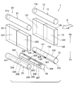
- the perspective view which shows schematic structure of the refrigerant evaporator concerning 1st Embodiment.
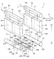
- the perspective view which shows the disassembled perspective structure of the refrigerant evaporator of 1st Embodiment.
- the perspective view which shows the disassembled perspective structure of the windward distribution tank of the refrigerant
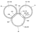
- Sectional drawing which shows the cross-section of the windward distribution tank of the refrigerant
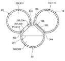
- Sectional drawing which shows the cross-section of the windward distribution tank of the refrigerant
- the perspective view which shows typically the flow of the refrigerant
- the perspective view which shows the disassembled perspective structure of the windward distribution tank of the refrigerant evaporator concerning 2nd Embodiment, a leeward collection tank, and a replacement
- the side view which shows the structure of the drainage groove
- the perspective view which shows the disassembled perspective structure of the windward distribution tank of the 1st modification of the refrigerant evaporator of 2nd Embodiment, a leeward collection tank, and a replacement tank.
- the perspective view which shows the disassembled perspective structure of the windward distribution tank of the 2nd modification of the refrigerant evaporator of 2nd Embodiment, a leeward collection tank, and a replacement tank.
- the refrigerant evaporator 1 of the present embodiment shown in FIG. 1 is used in a refrigeration cycle of a vehicle air conditioner that adjusts the temperature in the passenger compartment.
- the refrigerant evaporator 1 is a cooling heat exchanger that cools air by absorbing heat from air blown into the passenger compartment and evaporating liquid-phase refrigerant.
- the refrigeration cycle includes, in addition to the refrigerant evaporator 1, a compressor, a radiator, an expansion valve, and the like (not shown).
- the refrigerant evaporator 1 includes two evaporation units 10 and 20 and a replacement tank 30.
- the evaporation units 10 and 20 are arranged on the upstream side and the downstream side with respect to the air flow direction X.
- the air flow direction X is a direction orthogonal to the vertical directions Y1 and Y2.
- the evaporator 10 disposed on the upstream side in the air flow direction X is referred to as “windward evaporator 10”.
- the evaporation unit 20 disposed on the downstream side in the air flow direction X is referred to as a “leeward side evaporation unit 20”.
- the windward evaporator 10 includes a windward collecting tank 11, a windward heat exchange unit 12, and a windward distribution tank 13.
- the windward collecting tank 11, the windward heat exchange unit 12, and the windward distribution tank 13 are arranged in this order in the vertical direction downward Y1.
- the windward side heat exchanging section 12 has a rectangular parallelepiped shape.
- the windward heat exchange unit 12 is arranged so that the air flow direction X is the thickness direction.
- a windward distribution tank 13 is attached to an end surface 12d on the Y1 side in the vertical lower direction of the windward heat exchange unit 12.
- a windward collecting tank 11 is attached to an end face 12 e on the Y2 side in the vertical direction of the windward heat exchange unit 12.
- the windward heat exchange unit 12 has a structure in which a plurality of tubes 12a and a plurality of fins 12b are alternately stacked in the horizontal direction. In addition, illustration of the tube 12a and the fin 12b is abbreviate
- the tube 12a has a flat cross section and is arranged to extend in the vertical directions Y1 and Y2.
- a flow path through which a refrigerant flows is formed inside the tube 12a.
- the fins 12b are so-called corrugated fins formed by bending a thin metal plate.
- the fin 12b is arrange
- the windward heat exchange unit 12 is partitioned into a first windward core portion 121 and a second windward core portion 122 in the stacking direction of the tubes 12 a and the fins 12 b.
- the windward heat exchange unit 12 includes side plates 12c at both ends in the stacking direction of the tubes 12a and the fins 12b.
- the side plate 12 c is a member for reinforcing the windward heat exchange unit 12.
- the windward distribution tank 13 is formed of a cylindrical member having a refrigerant flow path therein. Both ends in the axial direction of the upwind distribution tank 13 are closed. As shown in FIG. 2, the upwind distribution tank 13 has a partition plate 13 a at the center in the axial direction. The partition plate 13 a partitions the internal flow path of the windward distribution tank 13 into a first distribution unit 131 and a second distribution unit 132. A plurality of through holes (not shown) are formed on the outer peripheral surface of the windward distribution tank 13 into which the end of the tube 12a on the lower side Y1 in the vertical direction is inserted.
- the internal flow path of the first distribution part 131 communicates with the tube 12a of the first upwind core part 121
- the internal flow path of the second distribution part 132 communicates with the tube 12a of the second upwind core part 122.
- the first distribution unit 131 distributes the refrigerant to the tube 12 a of the first upwind core unit 121.
- the second distribution unit 132 distributes the refrigerant to the tube 12 a of the second upwind core unit 122.
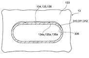
- a flat joint 133 is formed on the outer peripheral surface of the upwind distribution tank 13 so as to extend in the axial direction.
- the joining part 133 is a part to which the replacement tank 30 is joined.
- Through holes 134 and 135 are formed in the joint portion 133.
- the through hole 134 penetrates from the outer surface of the joint portion 133 to the internal flow path of the first distribution portion 131.
- the through hole 134 serves as a flow path for guiding the refrigerant in the replacement tank 30 to the first distributor 131.
- the through hole 135 penetrates from the outer surface of the joint part 133 to the internal flow path of the second distribution part 132.
- the through hole 135 serves as a flow path for guiding the refrigerant in the replacement tank 30 to the second distributor 132.
- a plurality of recesses 136 are formed in a portion of the windward distribution tank 13 where the through holes 134 and 135 are not formed.
- the recess 136 is formed in a groove shape so as not to penetrate the internal flow path of the windward distribution tank 13.
- illustration of the recessed part 136 is abbreviate
- the windward collecting tank 11 is formed of a cylindrical member having a refrigerant flow path therein. One end in the axial direction of the windward collecting tank 11 is closed. A refrigerant discharge port 11 a is formed at the other axial end of the windward collecting tank 11. The refrigerant discharge port 11a is connected to the suction side of a compressor (not shown). Further, on the outer peripheral surface of the windward collecting tank 11, a plurality of through holes (not shown) into which the ends on the Y2 side in the vertical direction of the tube 12a are inserted are formed.
- the internal flow path of the windward collecting tank 11 is communicated with the tube 12a of the first windward core part 121 and the tube 12a of the second windward core part 122 through the through holes. That is, the refrigerant flowing through the tube 12 a of the first upwind core portion 121 and the refrigerant flowing through the tube 12 a of the second upwind core portion 122 are collected in the upwind collecting tank 11. The refrigerant collected in the windward collecting tank 11 is guided to the compressor through the refrigerant discharge port 11a.
- the leeward evaporation unit 20 includes a leeward distribution tank 21, a leeward heat exchange unit 22, and a leeward collecting tank 23.
- the leeward side distribution tank 21, the leeward side heat exchange unit 22, and the leeward side collecting tank 23 are arranged in this order in the vertical direction downward Y1.
- the leeward side heat exchanging unit 22 has substantially the same structure as the leeward side heat exchanging unit 12. That is, the leeward side heat exchanging portion 22 has a rectangular parallelepiped shape, and is arranged such that the air flow direction X is the thickness direction.
- the leeward side heat exchanging section 22 has a structure in which a plurality of tubes 22a and a plurality of fins 22b are alternately stacked in the horizontal direction, and has side plates 22c at both ends in the stacking direction of the tubes 22a and the fins 22b. is doing.
- a leeward side collective tank 23 is attached to the end surface 22d of the leeward side heat exchanging unit 22 on the lower side Y1 in the vertical direction.
- a leeward distribution tank 21 is attached to an end face 22e on the Y2 side in the vertical direction of the leeward heat exchange unit 22. Further, as shown in FIG. 2, the leeward side heat exchanging unit 22 includes a first leeward side core portion 221 that faces the first leeward side core portion 121 in the air flow direction X and a second leeward side core portion 122. The second leeward core 222 is opposed to the second leeward core 222.
- the leeward side distribution tank 21 is formed of a cylindrical member having a refrigerant flow path therein. One end of the leeward side distribution tank 21 in the axial direction is closed. A refrigerant inlet 21 a is formed at the other axial end of the leeward distribution tank 21. Low-pressure refrigerant decompressed by an expansion valve (not shown) flows into the refrigerant inlet 21a. Further, on the outer peripheral surface of the leeward side distribution tank 21, a plurality of through holes (not shown) into which the end portion on the Y2 side in the vertical direction of the tube 22a is inserted are formed.
- the internal flow path of the leeward side distribution tank 21 is communicated with the tube 22a of the first leeward side core portion 221 and the tube 22a of the second leeward side core portion 222 through this through hole. That is, the refrigerant flowing into the leeward distribution tank 21 from the refrigerant inlet 21 a is distributed to the tube 22 a of the first leeward core portion 221 and the tube 22 a of the second leeward core portion 222.
- the leeward side collecting tank 23 is formed of a cylindrical member having a refrigerant flow path therein. Both axial ends of the leeward collecting tank 23 are closed.
- the leeward side collective tank 23 has a partition plate 23a at the center in the axial direction. As shown in FIG. 2, the partition plate 23 a partitions the internal flow path of the leeward collecting tank 23 into a first collecting portion 231 and a second collecting portion 232. Further, on the outer peripheral surface of the leeward side collective tank 23, a plurality of through holes (not shown) into which the ends of the tubes 22a on the lower side Y1 in the vertical direction are inserted are formed.
- the internal flow path of the first collecting portion 231 is communicated with the tube 22 a of the first leeward core portion 221, and the internal flow passage of the second collective portion 232 is communicated with the tube 22 a of the second leeward core portion 222.
- the refrigerant flowing through the tube 22 a of the first leeward core portion 221 is collected in the first collecting portion 231.
- the refrigerant flowing through the tube 22 a of the second leeward core portion 222 is collected in the second collecting portion 232.
- a planar joint 233 is formed on the outer peripheral surface of the leeward collecting tank 23 so as to extend in the axial direction.
- the joint part 233 is a part to which the replacement tank 30 is joined.
- Through holes 234 and 235 are formed in the joint portion 233.
- the through hole 235 penetrates from the outer surface of the joint portion 233 to the internal flow path of the second collecting portion 232.
- the through hole 235 serves as a flow path for guiding the refrigerant in the second collecting portion 232 to the replacement tank 30.
- the through hole 234 penetrates from the outer surface of the joint portion 233 to the internal flow path of the first collecting portion 231.
- the through hole 234 serves as a flow path for guiding the refrigerant in the first collecting portion 231 to the replacement tank 30.
- a plurality of recesses 236 are formed in a portion where the through holes 234 and 235 are not formed in the leeward side collecting tank 23.
- the concave portion 236 is formed in a groove shape so as not to penetrate the internal flow path of the leeward collecting tank 23.
- illustration of the recessed part 236 is abbreviate
- the leeward side collective tank 23 corresponds to the first tank
- the leeward side heat exchange unit 12 corresponds to the second tank.
- the leeward heat exchange unit 22 corresponds to a first heat exchange unit
- the leeward heat exchange unit 12 corresponds to a second heat exchange unit.
- the through holes 134 and 135 and the concave portion 136 of the upwind distribution tank 13 and the through holes 234 and 235 and the concave portion 236 of the leeward side collecting tank 23 correspond to the insertion portion.
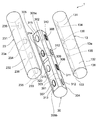
- the replacement tank 30 is provided between the leeward distribution tank 13 and the leeward collective tank 23.
- the replacement tank 30 corresponds to a third tank.
- the replacement tank 30 is formed of a cylindrical member having a refrigerant flow path therein.
- a partition member 301 is provided inside the replacement tank 30. The partition member 301 partitions the internal space of the replacement tank 30 into a first refrigerant channel 302 and a second refrigerant channel 303.
- a planar joint 304 to which the joint 133 of the upwind distribution tank 13 is joined and a joint 233 of the leeward collective tank 23 are joined to the outer peripheral surface of the replacement tank 30. And a planar joining portion 305 are formed.
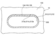
- the joint 304 includes a protrusion 310 inserted into the through hole 134 of the windward distribution tank 13, a protrusion 311 inserted into the through hole 135 of the windward distribution tank 13, and a recess 136 of the windward distribution tank 13. And a projecting portion 312 to be inserted into the housing. In FIG. 2, the protrusions 310 to 312 are not shown.
- a through hole 306 is formed in the protruding portion 310. As shown in FIG. 4, the through hole 306 penetrates the first refrigerant flow path 302 from the tip surface of the protrusion 310. The outer surface of the protrusion 310 is fixed to the inner peripheral surface of the through hole 134 of the upwind distribution tank 13 by brazing. As shown in FIG. 3, a through hole 308 is formed in the protrusion 311. As shown in FIG. 4, the through hole 308 passes through the second refrigerant flow path 303 from the tip surface of the protruding portion 311. The outer surface of the protrusion 311 is fixed to the inner surface of the through hole 135 of the upwind distribution tank 13 by brazing.
- the through holes 306 and 308 of the protrusions 310 and 311 and the through holes 134 and 135 of the upwind distribution tank 13 serve as a refrigerant flow path.
- the outer surface of the protrusion 312 is fixed to the inner surface of the recess 136 of the upwind distribution tank 13 by brazing.
- the protrusion 312 and the recess 136 are not formed with a coolant channel. That is, the protruding portion 312 and the recessed portion 136 are provided in a portion different from the portion where the refrigerant flow path is formed in the replacement tank 30 and the upwind distribution tank 13.
- the joint 305 includes a protrusion 313 inserted into the through hole 235 of the leeward side collective tank 23, and a protrusion 314 inserted into the through hole 234 of the leeward side collective tank 23, A protrusion 315 to be inserted into the recess 236 of the leeward collecting tank 23 is provided.
- the protrusions 313 to 315 are not shown.
- a through hole 307 is formed in the protruding portion 313. As shown in FIG. 5, the through hole 307 penetrates the first refrigerant flow path 302 from the tip surface of the protrusion 313. The outer surface of the protruding portion 313 is fixed to the inner peripheral surface of the through hole 235 of the leeward side collecting tank 23 by brazing. As shown in FIG. 3, a through hole 309 is formed in the protrusion 314. As shown in FIG. 5, the through hole 309 passes through the second refrigerant flow path 303 from the tip surface of the protrusion 314. The outer surface of the protruding portion 314 is fixed to the inner peripheral surface of the through hole 234 of the leeward side collecting tank 23 by brazing.
- the through holes 307 and 309 of the projecting portions 313 and 314 and the through holes 234 and 235 of the leeward side collecting tank 23 serve as a refrigerant flow path.
- the outer surface of the projecting portion 315 is fixed to the inner surface of the concave portion 236 of the leeward collecting tank 23 by brazing.
- the protrusion 315 and the recess 236 are not formed with a coolant channel.
- the protruding portion 315 and the recessed portion 236 are provided in a portion different from the portion where the refrigerant flow path is formed in the replacement tank 30 and the leeward side collecting tank 23.
- the refrigerant collected in the first collecting portion 231 of the leeward side collecting tank 23 is transferred to the second refrigerant flow path 303 via the through hole 234 of the leeward side collecting tank 23 and the through hole 309 of the replacement tank 30. Inflow.
- the refrigerant flowing into the second refrigerant flow path 303 is guided to the second distribution part 132 of the upwind distribution tank 13 through the through hole 308 of the replacement tank 30 and the through hole 135 of the upwind distribution tank 13.
- the refrigerant collected in the second collecting portion 232 of the leeward collecting tank 23 flows into the first refrigerant flow path 302 through the through hole 235 of the leeward collecting tank 23 and the through hole 307 of the replacement tank 30.
- the refrigerant flowing into the first refrigerant flow path 302 is guided to the first distribution part 131 of the upwind distribution tank 13 through the through hole 306 of the replacement tank 30 and the through hole 134 of the upwind distribution tank 13.
- the replacement tank 30 functions as a portion that guides the refrigerant collected in the leeward collecting tank 23 to the leeward distribution tank 13.
- the replacement tank 30 functions as a portion that exchanges the refrigerant flow in the leeward heat exchange unit 22 and the refrigerant flow in the leeward heat exchange unit 12 in the stacking direction of the tubes 12a and 22a.
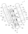
- the refrigerant depressurized by an unillustrated expansion valve is introduced into the leeward distribution tank 21 from the refrigerant inlet 21a as indicated by an arrow A in FIG.
- This refrigerant is distributed inside the leeward distribution tank 21 and flows into the first leeward core portion 221 and the second leeward core portion 222 of the leeward distribution tank 21 as indicated by arrows B and C.
- the refrigerant flowing through the tube 22 a of the first leeward core portion 221 is collected in the first collecting portion 231 of the leeward collecting tank 23 as indicated by an arrow D.
- the refrigerant collected in the first collecting portion 231 flows into the second distribution portion 132 of the upwind distribution tank 13 through the second refrigerant flow path 303 of the replacement tank 30 as indicated by an arrow F.
- the refrigerant flowing into the second distribution unit 132 flows into the second upwind core unit 122 as indicated by the arrow H.
- the refrigerant flowing through the tube 22a of the second leeward core portion 222 is collected in the second collecting portion 232 of the leeward collecting tank 23 as indicated by an arrow E.
- the refrigerant collected in the second collecting portion 232 flows into the first distribution portion 131 of the upwind distribution tank 13 through the first refrigerant flow path 302 of the replacement tank 30 as indicated by an arrow G.
- the refrigerant flowing into the first distribution unit 131 flows into the first upwind core unit 121 as indicated by the arrow I.
- the refrigerant flowing through the first windward core portion 121 and the second windward core portion 122 is collected in the windward collecting tank 11 as indicated by arrows K and J. As indicated by an arrow L, the refrigerant collected in the windward collecting tank 11 is supplied from the refrigerant discharge port 11a of the windward collecting tank 11 to the suction side of a compressor (not shown).
- the inner surfaces of the through holes 134 and 135 of the upwind distribution tank 13 and the projecting portion 310 of the replacement tank 30 The part of the 311 that contacts the outer surface is the starting point of brazing. Further, the contact portion between the inner surface of the concave portion 136 of the upwind distribution tank 13 and the outer surface of the protruding portion 312 of the replacement tank 30 is also a starting point of brazing.
- the part of the portion 315 that contacts the outer surface is also the starting point of brazing.
- a drainage groove 320 is formed in the joint portion 305 of the replacement tank 30.
- the drainage groove 320 is formed in the vicinity of the central portion in the longitudinal direction of the joint portion 305 and between the protruding portion 314 and the protruding portion 315.
- one end of the drainage groove 320 is open to a gap CL formed between the windward distribution tank 13, the leeward collecting tank 23, and the replacement tank 30.
- the other end of the drainage groove 320 is open to a space on the Y1 side in the vertical direction of the leeward side collecting tank 23.
- the condensed water stored in the gap CL is discharged to the outside through the drainage groove 320 as indicated by an arrow W in FIG. Therefore, since it becomes difficult to store condensed water in the gap CL, it is possible to suppress freeze cracking caused by freezing of condensed water.
- the junction 305 of the replacement tank 30 is divided into two locations 305a and 305b by the drainage groove 320 as shown in FIG. In the case of such a structure, it is necessary to perform brazing at each of the divided portions 305a and 305b.
- the one portion 305a that is divided is brazed between the through hole 234 of the leeward side collecting tank 23 and the protruding portion 314 of the replacement tank 30, and the leeward side collecting.
- the other part 306b divided is a brazed part between the through-hole 235 of the leeward side collective tank 23 and the protruding part 313 of the exchange tank 30, and the concave part 236 of the leeward side collective tank 23 and the protrusion of the exchange tank 30.
- a brazed portion with the portion 315 exists.
- brazing can be performed at each of the divided portions 305a and 305b, so that the brazing performance between the leeward collecting tank 23 and the replacement tank 30 can be stabilized.
- a drainage groove 237 is formed in the joint 233 of the leeward side collecting tank 23.
- the drainage groove 237 is formed in the vicinity of the central portion in the longitudinal direction of the joint portion 233 and between the through hole 234 and the recess 236.
- the drainage groove 237 communicates the gap CL formed between the tanks 13, 23, and 30 with the space on the Y1 side in the vertical direction lower side of the leeward side collecting tank 23.
- a plurality of drain grooves 320 are formed on the inclined surface of the joint portion 305 of the replacement tank 30.
- the drainage groove 320 is formed between the protruding portion 314 and the two protruding portions 315 and between the protruding portion 313 and the protruding portion 315, respectively.
- the drainage groove 320 communicates the gap CL formed between the tanks 13, 23, 30 and the space on the Y1 side in the vertical direction of the leeward side collecting tank 23.
- a plurality of drain grooves 321 are also formed on the inclined surface of the joint 304 of the replacement tank 30. Specifically, the drainage groove 321 is formed between the protrusion 310 and the protrusion 312 and between the protrusion 311 and the two protrusions 312. The drainage groove 321 communicates the gap CL formed between the tanks 13, 23, and 30 with the space on the Y1 side in the vertical direction of the upwind distribution tank 13.
- the part is divided by the drainage groove 320.
- the location is divided by a drainage groove 321.
- brazing can be performed at the respective portions separated by the drainage grooves 320 and 321 at the joint portions 304 and 305 of the replacement tank 30, so that the upwind distribution tank 13 and the replacement tank 30 The brazing performance of the leeward side collecting tank 23 and the replacement tank 30 can be stabilized.
- a plurality of drain grooves 137 are formed in the joint portion 133 of the upwind distribution tank 13. Specifically, the drainage groove 137 is formed between the through hole 134 and the recess 136 and between the through hole 135 and the two recesses. The drainage groove 137 communicates the clearance CL formed between the tanks 13, 23, and 30 with the space on the Y1 side in the vertical direction of the upwind distribution tank 13.
- a plurality of drain grooves 237 are also formed in the joint portion 233 of the leeward collecting tank 23. Specifically, the drainage groove 237 is formed between the through hole 234 and the two recesses 236 and between the through hole 235 and the recess 236. The drainage groove 237 communicates the gap CL formed between the tanks 13, 23, and 30 with the space on the Y1 side in the vertical direction lower side of the leeward side collecting tank 23.
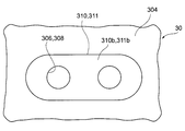
- two through-holes 306 and 308 constituting a refrigerant flow path are formed on the tip surfaces 310b and 311b of the protrusions 310 and 311 provided at the joint 304 of the replacement tank 30, respectively.
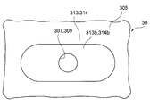
- one through-holes 307 and 309 constituting a refrigerant flow path are formed on the front end surfaces 313 b and 314 b of the protruding portions 313 and 314 provided at the joint portion 305 of the replacement tank 30.
- the through holes 306 to 309 have the same shape.
- the total cross-sectional area of each of the through holes 306 and 308 formed in the protrusions 310 and 311 is equal to that of each of the through holes 307 and 309 formed in the protrusions 313 and 314. It is different from the area.
- the total cross-sectional area indicates the total cross-sectional area of each through hole formed in one projecting portion.
- the distribution amount of the refrigerant in each of the leeward core portions 121 and 122 and the leeward core portions 221 and 222 can be adjusted. As a result, it is possible to adjust the heat exchange performance of each of the leeward core portions 121 and 122 and the leeward core portions 221 and 222. In addition, the refrigerant distribution amount in each of the windward core portions 121 and 122 and the leeward core portions 221 and 222 can be easily changed only by changing the number of each of the through holes 306 to 309.
- the replacement tank 30 of this embodiment can be manufactured by the following method, for example. First, a replacement tank 30 is prepared in which protrusions 310, 311, 313, 314 in which the through holes 306 to 309 are not formed and protrusions 312, 315 are formed. Thereafter, the replacement tank 30 can be manufactured by forming a necessary number of through holes in the projecting portions 310, 311, 313, and 314 with a common punching die corresponding to the shape of the through holes 306 to 309. According to such a manufacturing method, the through holes formed in the protrusions 310, 311, 313, and 314 when adjusting the refrigerant distribution amount of the leeward core portions 121 and 122 and the leeward core portions 221 and 222. Since only the number of 306 to 309 needs to be changed, productivity can be improved. Further, since it is not necessary to change the punching die for forming the through holes 306 to 309, the cost can be reduced.
- each embodiment can also be implemented with the following forms.
- one or more combinations of the drainage groove 320 formed in the joint portion 305 of the replacement tank 30 and the drainage groove 237 formed in the joint portion 233 of the leeward side collecting tank 23 are used.
- a plurality of drainage grooves may be configured.
- one or a plurality of drainage grooves are configured by a combination of the drainage groove 321 formed in the joint portion 304 of the replacement tank 30 and the drainage groove 137 formed in the joint portion 133 of the upwind distribution tank 13. May be.
- a protrusion 134 a that contacts the outer surface of the protrusion 310 of the replacement tank 30 may be formed on the inner surface of the through-hole 134 of the upwind distribution tank 13.
- protrusions 135 a and 136 a that contact the outer surfaces of the protrusions 311 and 312 of the replacement tank 30 may be formed on the inner surfaces of the through holes 135 and the recesses 136 of the upwind distribution tank 13, respectively.
- protrusions 310 to 312 of the replacement tank 30 can be more reliably fixed to the through holes 134 and 135 and the recess 136 of the upwind distribution tank 13.
- protrusions may be formed on the inner surfaces of the through holes 234 and 235 and the recess 236 of the leeward side collecting tank 23.
- a protrusion 310 a that contacts the inner surface of the through hole 134 of the upwind distribution tank 13 may be formed on the outer surface of the protrusion 310 of the replacement tank 30.
- protrusions 311 a and 312 a that contact the inner surfaces of the through holes 135 and the recesses 136 of the upwind distribution tank 13 may be formed on the outer surfaces of the protrusions 311 and 312 of the replacement tank 30. Even with such a configuration, the same operations and effects as the structure illustrated in FIG. 14 can be obtained.
- protrusions may be formed on the outer surfaces of the protrusions 313 to 315 of the replacement tank 30.
- the shape of the through holes 134 and 135 and the recess 136 of the windward distribution tank 13 can be changed as appropriate.
- the shapes of the through holes 234 and 235 and the recess 236 of the leeward collecting tank 23 can be changed as appropriate.
- the shape of the protrusions 310 to 315 of the replacement tank 30 can be changed as appropriate.
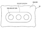
- a plurality of through holes 306 may be formed in the protruding portion 310 of the replacement tank 30 as shown in FIG.
- a plurality of through holes 308, 307, and 309 may be formed for the protruding portions 311, 313, and 314 of the replacement tank 30.
- the number of through holes 306 to 309 formed in the protrusions 310, 311, 313, and 314 may be appropriately changed.
- the protrusions 310, 311, 313, and 314 may be formed with one or a plurality of through-holes that constitute the refrigerant flow path.
- the number of through holes formed in at least one of the plurality of protrusions may be different from the number of through holes formed in the other protrusions.
- the total cross-sectional area of the through hole formed in at least one of the plurality of protrusions may be different from the total cross-sectional area of the through hole formed in the other protrusion.
- the cross-sectional area of the through-hole 134 of the windward distribution tank 13 may be different from the cross-sectional area of the through-hole 306 formed in the protrusion 310 of the replacement tank 30.
- the flow rate (distribution amount) of the refrigerant flowing from the replacement tank 30 to the first distribution unit 131 of the upwind distribution tank 13 can be adjusted.
- the protrusions 310 to 312 are formed in the joint portion 304 of the replacement tank 30, and the through holes 134 and 135 and the concave portion 136 as insertion portions are formed in the joint portion 133 of the upwind distribution tank 13.
- a protrusion may be formed at the joint 133 of the upwind distribution tank 13, and an insertion part into which the protrusion is inserted may be formed at the joint 304 of the replacement tank 30.
- a protruding portion may be formed in the joint portion 233 of the leeward side collecting tank 23, and an insertion portion into which the protruding portion is inserted may be formed in the joint portion 305 of the replacement tank 30.
- the fluid to be cooled in the refrigerant evaporator 1 is not limited to air, and an appropriate fluid can be used.
Landscapes
- Engineering & Computer Science (AREA)
- Physics & Mathematics (AREA)
- Thermal Sciences (AREA)
- Mechanical Engineering (AREA)
- General Engineering & Computer Science (AREA)
- Heat-Exchange Devices With Radiators And Conduit Assemblies (AREA)
- Details Of Heat-Exchange And Heat-Transfer (AREA)
Priority Applications (3)
| Application Number | Priority Date | Filing Date | Title |
|---|---|---|---|
| DE112016000963.1T DE112016000963B4 (de) | 2015-02-27 | 2016-02-25 | Kältemittel-Verdampfer |
| US15/547,302 US10352601B2 (en) | 2015-02-27 | 2016-02-25 | Refrigerant evaporator |
| CN201680004117.4A CN107003090A (zh) | 2015-02-27 | 2016-02-25 | 制冷剂蒸发器 |
Applications Claiming Priority (4)
| Application Number | Priority Date | Filing Date | Title |
|---|---|---|---|
| JP2015-038170 | 2015-02-27 | ||
| JP2015038170 | 2015-02-27 | ||
| JP2015156956 | 2015-08-07 | ||
| JP2015-156956 | 2015-08-07 |
Publications (1)
| Publication Number | Publication Date |
|---|---|
| WO2016136265A1 true WO2016136265A1 (ja) | 2016-09-01 |
Family
ID=56788327
Family Applications (1)
| Application Number | Title | Priority Date | Filing Date |
|---|---|---|---|
| PCT/JP2016/001022 Ceased WO2016136265A1 (ja) | 2015-02-27 | 2016-02-25 | 冷媒蒸発器 |
Country Status (5)
| Country | Link |
|---|---|
| US (1) | US10352601B2 (enExample) |
| JP (1) | JP6558269B2 (enExample) |
| CN (1) | CN107003090A (enExample) |
| DE (1) | DE112016000963B4 (enExample) |
| WO (1) | WO2016136265A1 (enExample) |
Cited By (2)
| Publication number | Priority date | Publication date | Assignee | Title |
|---|---|---|---|---|
| JP2016164486A (ja) * | 2015-02-27 | 2016-09-08 | 株式会社デンソー | 冷媒蒸発器 |
| JP2017032262A (ja) * | 2015-02-27 | 2017-02-09 | 株式会社デンソー | 冷媒蒸発器 |
Families Citing this family (3)
| Publication number | Priority date | Publication date | Assignee | Title |
|---|---|---|---|---|
| JP7467927B2 (ja) * | 2020-01-20 | 2024-04-16 | 株式会社デンソー | 熱交換器 |
| CN115289720B (zh) * | 2022-08-03 | 2023-07-28 | 西安交通大学 | 一种双排微通道蒸发器及其工作方法 |
| KR20240055995A (ko) * | 2022-10-21 | 2024-04-30 | 한온시스템 주식회사 | 일체형 커넥터 및 이를 포함한 열교환기 |
Citations (7)
| Publication number | Priority date | Publication date | Assignee | Title |
|---|---|---|---|---|
| JPS6234964U (enExample) * | 1985-08-22 | 1987-03-02 | ||
| JPS6334491A (ja) * | 1986-07-29 | 1988-02-15 | Toyo Radiator Kk | 熱交換器のチユ−ブ接合部 |
| JPH0741282U (ja) * | 1993-12-22 | 1995-07-21 | 株式会社日本クライメイトシステムズ | 熱交換器 |
| JP2003214794A (ja) * | 2002-01-23 | 2003-07-30 | Denso Corp | 熱交換器 |
| JP2010197019A (ja) * | 2009-02-27 | 2010-09-09 | Showa Denko Kk | エバポレータ |
| JP2014228155A (ja) * | 2013-05-20 | 2014-12-08 | カルソニックカンセイ株式会社 | リキッドタンク一体型コンデンサ、リキッドタンクおよびリキッドタンク一体型コンデンサの製造方法 |
| JP2014228234A (ja) * | 2013-05-24 | 2014-12-08 | 株式会社デンソー | 冷媒蒸発器 |
Family Cites Families (23)
| Publication number | Priority date | Publication date | Assignee | Title |
|---|---|---|---|---|
| JP3575497B2 (ja) * | 1994-10-06 | 2004-10-13 | 株式会社デンソー | 受液器一体型冷媒凝縮器およびその製造方法 |
| JP2001050686A (ja) * | 1999-08-05 | 2001-02-23 | Denso Corp | 蒸発器 |
| JP4124136B2 (ja) * | 2003-04-21 | 2008-07-23 | 株式会社デンソー | 冷媒蒸発器 |
| KR20060125775A (ko) * | 2003-10-29 | 2006-12-06 | 쇼와 덴코 가부시키가이샤 | 열교환기 |
| JP4625687B2 (ja) * | 2003-12-08 | 2011-02-02 | 昭和電工株式会社 | 熱交換器 |
| JP4120611B2 (ja) | 2004-04-08 | 2008-07-16 | 株式会社デンソー | 冷媒蒸発器 |
| JP2006029765A (ja) * | 2004-06-15 | 2006-02-02 | Showa Denko Kk | 熱交換器 |
| JP2006029697A (ja) * | 2004-07-16 | 2006-02-02 | Denso Corp | 冷媒蒸発器 |
| JP2006194576A (ja) * | 2004-12-16 | 2006-07-27 | Showa Denko Kk | エバポレータ |
| US8037929B2 (en) | 2004-12-16 | 2011-10-18 | Showa Denko K.K. | Evaporator |
| DE102010031406B4 (de) | 2010-07-15 | 2020-01-30 | Mahle International Gmbh | Verdampfervorrichtung |
| JP5868088B2 (ja) * | 2011-09-15 | 2016-02-24 | 株式会社ケーヒン・サーマル・テクノロジー | 車両用空調装置のクーリングユニット |
| JP5454553B2 (ja) * | 2011-11-01 | 2014-03-26 | 株式会社デンソー | 冷媒蒸発器 |
| JP5796518B2 (ja) * | 2012-03-06 | 2015-10-21 | 株式会社デンソー | 冷媒蒸発器 |
| KR101457585B1 (ko) * | 2012-05-22 | 2014-11-03 | 한라비스테온공조 주식회사 | 증발기 |
| JP6131705B2 (ja) | 2013-05-10 | 2017-05-24 | 株式会社デンソー | 冷媒蒸発器 |
| JP6098343B2 (ja) | 2013-05-10 | 2017-03-22 | 株式会社デンソー | 冷媒蒸発器 |
| WO2014181550A1 (ja) | 2013-05-10 | 2014-11-13 | 株式会社デンソー | 冷媒蒸発器 |
| JP6423998B2 (ja) | 2013-08-19 | 2018-11-14 | 学校法人 関西大学 | 過冷却促進剤、及び、過冷却促進剤の製造方法 |
| JP5888755B2 (ja) | 2014-02-24 | 2016-03-22 | 朝日インテック株式会社 | カテーテル |
| JP2016032054A (ja) | 2014-07-30 | 2016-03-07 | パナソニックIpマネジメント株式会社 | 希土類系ボンド磁石、希土類系ボンド磁石の製造方法、モータ |
| JP6558268B2 (ja) | 2015-02-27 | 2019-08-14 | 株式会社デンソー | 冷媒蒸発器 |
| JP6558269B2 (ja) * | 2015-02-27 | 2019-08-14 | 株式会社デンソー | 冷媒蒸発器 |
-
2016
- 2016-02-23 JP JP2016032054A patent/JP6558269B2/ja active Active
- 2016-02-25 WO PCT/JP2016/001022 patent/WO2016136265A1/ja not_active Ceased
- 2016-02-25 CN CN201680004117.4A patent/CN107003090A/zh active Pending
- 2016-02-25 US US15/547,302 patent/US10352601B2/en active Active
- 2016-02-25 DE DE112016000963.1T patent/DE112016000963B4/de active Active
Patent Citations (7)
| Publication number | Priority date | Publication date | Assignee | Title |
|---|---|---|---|---|
| JPS6234964U (enExample) * | 1985-08-22 | 1987-03-02 | ||
| JPS6334491A (ja) * | 1986-07-29 | 1988-02-15 | Toyo Radiator Kk | 熱交換器のチユ−ブ接合部 |
| JPH0741282U (ja) * | 1993-12-22 | 1995-07-21 | 株式会社日本クライメイトシステムズ | 熱交換器 |
| JP2003214794A (ja) * | 2002-01-23 | 2003-07-30 | Denso Corp | 熱交換器 |
| JP2010197019A (ja) * | 2009-02-27 | 2010-09-09 | Showa Denko Kk | エバポレータ |
| JP2014228155A (ja) * | 2013-05-20 | 2014-12-08 | カルソニックカンセイ株式会社 | リキッドタンク一体型コンデンサ、リキッドタンクおよびリキッドタンク一体型コンデンサの製造方法 |
| JP2014228234A (ja) * | 2013-05-24 | 2014-12-08 | 株式会社デンソー | 冷媒蒸発器 |
Cited By (2)
| Publication number | Priority date | Publication date | Assignee | Title |
|---|---|---|---|---|
| JP2016164486A (ja) * | 2015-02-27 | 2016-09-08 | 株式会社デンソー | 冷媒蒸発器 |
| JP2017032262A (ja) * | 2015-02-27 | 2017-02-09 | 株式会社デンソー | 冷媒蒸発器 |
Also Published As
| Publication number | Publication date |
|---|---|
| DE112016000963B4 (de) | 2025-01-16 |
| CN107003090A (zh) | 2017-08-01 |
| US10352601B2 (en) | 2019-07-16 |
| US20180023872A1 (en) | 2018-01-25 |
| JP2017032262A (ja) | 2017-02-09 |
| JP6558269B2 (ja) | 2019-08-14 |
| DE112016000963T5 (de) | 2017-11-16 |
Similar Documents
| Publication | Publication Date | Title |
|---|---|---|
| JP6558269B2 (ja) | 冷媒蒸発器 | |
| US10337808B2 (en) | Condenser | |
| US10107532B2 (en) | Refrigerant evaporator having a tank external refrigerant space | |
| WO2014041771A1 (ja) | 熱交換器 | |
| CN110651162B (zh) | 制冷剂蒸发器及其制造方法 | |
| JP2007155268A (ja) | 熱交換器および冷媒蒸発器 | |
| JP6160385B2 (ja) | 積層型熱交換器 | |
| US20120198882A1 (en) | Evaporator | |
| JP6558268B2 (ja) | 冷媒蒸発器 | |
| CN111448438A (zh) | 热交换器 | |
| JP6413760B2 (ja) | 熱交換器及びそれを用いた熱交換器ユニット | |
| JP6613996B2 (ja) | 冷媒蒸発器 | |
| JP2017190896A (ja) | 熱交換器 | |
| JP2016080236A (ja) | 熱交換器 | |
| JP6477314B2 (ja) | 冷媒蒸発器 | |
| JP5947158B2 (ja) | ヒートポンプ用室外熱交換器 | |
| JP6582373B2 (ja) | 熱交換器 | |
| JP6583080B2 (ja) | 冷媒蒸発器 | |
| JP6432275B2 (ja) | 冷媒蒸発器 | |
| JP7081417B2 (ja) | 熱交換器 | |
| JP2008256248A (ja) | 冷却用熱交換器 | |
| JP6642326B2 (ja) | 冷媒蒸発器 | |
| JP6720890B2 (ja) | 積層型熱交換器 | |
| JP2012067957A (ja) | 熱交換器およびそれを用いたヒートポンプ式車両用空調装置 | |
| JP2018159479A (ja) | 熱交換器 |
Legal Events
| Date | Code | Title | Description |
|---|---|---|---|
| 121 | Ep: the epo has been informed by wipo that ep was designated in this application |
Ref document number: 16755015 Country of ref document: EP Kind code of ref document: A1 |
|
| WWE | Wipo information: entry into national phase |
Ref document number: 15547302 Country of ref document: US |
|
| WWE | Wipo information: entry into national phase |
Ref document number: 112016000963 Country of ref document: DE |
|
| 122 | Ep: pct application non-entry in european phase |
Ref document number: 16755015 Country of ref document: EP Kind code of ref document: A1 |