WO2016132938A1 - ブレーキ装置 - Google Patents
ブレーキ装置 Download PDFInfo
- Publication number
- WO2016132938A1 WO2016132938A1 PCT/JP2016/053607 JP2016053607W WO2016132938A1 WO 2016132938 A1 WO2016132938 A1 WO 2016132938A1 JP 2016053607 W JP2016053607 W JP 2016053607W WO 2016132938 A1 WO2016132938 A1 WO 2016132938A1
- Authority
- WO
- WIPO (PCT)
- Prior art keywords
- brake
- chamber
- amount
- oil passage
- piston
- Prior art date
- Legal status (The legal status is an assumption and is not a legal conclusion. Google has not performed a legal analysis and makes no representation as to the accuracy of the status listed.)
- Ceased
Links
Images

Classifications
-
- B—PERFORMING OPERATIONS; TRANSPORTING
- B60—VEHICLES IN GENERAL
- B60T—VEHICLE BRAKE CONTROL SYSTEMS OR PARTS THEREOF; BRAKE CONTROL SYSTEMS OR PARTS THEREOF, IN GENERAL; ARRANGEMENT OF BRAKING ELEMENTS ON VEHICLES IN GENERAL; PORTABLE DEVICES FOR PREVENTING UNWANTED MOVEMENT OF VEHICLES; VEHICLE MODIFICATIONS TO FACILITATE COOLING OF BRAKES
- B60T8/00—Arrangements for adjusting wheel-braking force to meet varying vehicular or ground-surface conditions, e.g. limiting or varying distribution of braking force
- B60T8/32—Arrangements for adjusting wheel-braking force to meet varying vehicular or ground-surface conditions, e.g. limiting or varying distribution of braking force responsive to a speed condition, e.g. acceleration or deceleration
- B60T8/34—Arrangements for adjusting wheel-braking force to meet varying vehicular or ground-surface conditions, e.g. limiting or varying distribution of braking force responsive to a speed condition, e.g. acceleration or deceleration having a fluid pressure regulator responsive to a speed condition
- B60T8/40—Arrangements for adjusting wheel-braking force to meet varying vehicular or ground-surface conditions, e.g. limiting or varying distribution of braking force responsive to a speed condition, e.g. acceleration or deceleration having a fluid pressure regulator responsive to a speed condition comprising an additional fluid circuit including fluid pressurising means for modifying the pressure of the braking fluid, e.g. including wheel driven pumps for detecting a speed condition, or pumps which are controlled by means independent of the braking system
- B60T8/4072—Systems in which a driver input signal is used as a control signal for the additional fluid circuit which is normally used for braking
- B60T8/4081—Systems with stroke simulating devices for driver input
- B60T8/4086—Systems with stroke simulating devices for driver input the stroke simulating device being connected to, or integrated in the driver input device
-
- B—PERFORMING OPERATIONS; TRANSPORTING
- B60—VEHICLES IN GENERAL
- B60T—VEHICLE BRAKE CONTROL SYSTEMS OR PARTS THEREOF; BRAKE CONTROL SYSTEMS OR PARTS THEREOF, IN GENERAL; ARRANGEMENT OF BRAKING ELEMENTS ON VEHICLES IN GENERAL; PORTABLE DEVICES FOR PREVENTING UNWANTED MOVEMENT OF VEHICLES; VEHICLE MODIFICATIONS TO FACILITATE COOLING OF BRAKES
- B60T8/00—Arrangements for adjusting wheel-braking force to meet varying vehicular or ground-surface conditions, e.g. limiting or varying distribution of braking force
- B60T8/32—Arrangements for adjusting wheel-braking force to meet varying vehicular or ground-surface conditions, e.g. limiting or varying distribution of braking force responsive to a speed condition, e.g. acceleration or deceleration
- B60T8/34—Arrangements for adjusting wheel-braking force to meet varying vehicular or ground-surface conditions, e.g. limiting or varying distribution of braking force responsive to a speed condition, e.g. acceleration or deceleration having a fluid pressure regulator responsive to a speed condition
- B60T8/40—Arrangements for adjusting wheel-braking force to meet varying vehicular or ground-surface conditions, e.g. limiting or varying distribution of braking force responsive to a speed condition, e.g. acceleration or deceleration having a fluid pressure regulator responsive to a speed condition comprising an additional fluid circuit including fluid pressurising means for modifying the pressure of the braking fluid, e.g. including wheel driven pumps for detecting a speed condition, or pumps which are controlled by means independent of the braking system
- B60T8/4072—Systems in which a driver input signal is used as a control signal for the additional fluid circuit which is normally used for braking
- B60T8/4081—Systems with stroke simulating devices for driver input
-
- B—PERFORMING OPERATIONS; TRANSPORTING
- B60—VEHICLES IN GENERAL
- B60T—VEHICLE BRAKE CONTROL SYSTEMS OR PARTS THEREOF; BRAKE CONTROL SYSTEMS OR PARTS THEREOF, IN GENERAL; ARRANGEMENT OF BRAKING ELEMENTS ON VEHICLES IN GENERAL; PORTABLE DEVICES FOR PREVENTING UNWANTED MOVEMENT OF VEHICLES; VEHICLE MODIFICATIONS TO FACILITATE COOLING OF BRAKES
- B60T11/00—Transmitting braking action from initiating means to ultimate brake actuator without power assistance or drive or where such assistance or drive is irrelevant
- B60T11/10—Transmitting braking action from initiating means to ultimate brake actuator without power assistance or drive or where such assistance or drive is irrelevant transmitting by fluid means, e.g. hydraulic
- B60T11/16—Master control, e.g. master cylinders
- B60T11/20—Tandem, side-by-side, or other multiple master cylinder units
-
- B—PERFORMING OPERATIONS; TRANSPORTING
- B60—VEHICLES IN GENERAL
- B60T—VEHICLE BRAKE CONTROL SYSTEMS OR PARTS THEREOF; BRAKE CONTROL SYSTEMS OR PARTS THEREOF, IN GENERAL; ARRANGEMENT OF BRAKING ELEMENTS ON VEHICLES IN GENERAL; PORTABLE DEVICES FOR PREVENTING UNWANTED MOVEMENT OF VEHICLES; VEHICLE MODIFICATIONS TO FACILITATE COOLING OF BRAKES
- B60T13/00—Transmitting braking action from initiating means to ultimate brake actuator with power assistance or drive; Brake systems incorporating such transmitting means, e.g. air-pressure brake systems
- B60T13/10—Transmitting braking action from initiating means to ultimate brake actuator with power assistance or drive; Brake systems incorporating such transmitting means, e.g. air-pressure brake systems with fluid assistance, drive, or release
- B60T13/12—Transmitting braking action from initiating means to ultimate brake actuator with power assistance or drive; Brake systems incorporating such transmitting means, e.g. air-pressure brake systems with fluid assistance, drive, or release the fluid being liquid
- B60T13/14—Transmitting braking action from initiating means to ultimate brake actuator with power assistance or drive; Brake systems incorporating such transmitting means, e.g. air-pressure brake systems with fluid assistance, drive, or release the fluid being liquid using accumulators or reservoirs fed by pumps
- B60T13/142—Systems with master cylinder
- B60T13/145—Master cylinder integrated or hydraulically coupled with booster
- B60T13/146—Part of the system directly actuated by booster pressure
-
- B—PERFORMING OPERATIONS; TRANSPORTING
- B60—VEHICLES IN GENERAL
- B60T—VEHICLE BRAKE CONTROL SYSTEMS OR PARTS THEREOF; BRAKE CONTROL SYSTEMS OR PARTS THEREOF, IN GENERAL; ARRANGEMENT OF BRAKING ELEMENTS ON VEHICLES IN GENERAL; PORTABLE DEVICES FOR PREVENTING UNWANTED MOVEMENT OF VEHICLES; VEHICLE MODIFICATIONS TO FACILITATE COOLING OF BRAKES
- B60T13/00—Transmitting braking action from initiating means to ultimate brake actuator with power assistance or drive; Brake systems incorporating such transmitting means, e.g. air-pressure brake systems
- B60T13/10—Transmitting braking action from initiating means to ultimate brake actuator with power assistance or drive; Brake systems incorporating such transmitting means, e.g. air-pressure brake systems with fluid assistance, drive, or release
- B60T13/66—Electrical control in fluid-pressure brake systems
- B60T13/662—Electrical control in fluid-pressure brake systems characterised by specified functions of the control system components
-
- B—PERFORMING OPERATIONS; TRANSPORTING
- B60—VEHICLES IN GENERAL
- B60T—VEHICLE BRAKE CONTROL SYSTEMS OR PARTS THEREOF; BRAKE CONTROL SYSTEMS OR PARTS THEREOF, IN GENERAL; ARRANGEMENT OF BRAKING ELEMENTS ON VEHICLES IN GENERAL; PORTABLE DEVICES FOR PREVENTING UNWANTED MOVEMENT OF VEHICLES; VEHICLE MODIFICATIONS TO FACILITATE COOLING OF BRAKES
- B60T13/00—Transmitting braking action from initiating means to ultimate brake actuator with power assistance or drive; Brake systems incorporating such transmitting means, e.g. air-pressure brake systems
- B60T13/10—Transmitting braking action from initiating means to ultimate brake actuator with power assistance or drive; Brake systems incorporating such transmitting means, e.g. air-pressure brake systems with fluid assistance, drive, or release
- B60T13/66—Electrical control in fluid-pressure brake systems
- B60T13/68—Electrical control in fluid-pressure brake systems by electrically-controlled valves
- B60T13/686—Electrical control in fluid-pressure brake systems by electrically-controlled valves in hydraulic systems or parts thereof
-
- B—PERFORMING OPERATIONS; TRANSPORTING
- B60—VEHICLES IN GENERAL
- B60T—VEHICLE BRAKE CONTROL SYSTEMS OR PARTS THEREOF; BRAKE CONTROL SYSTEMS OR PARTS THEREOF, IN GENERAL; ARRANGEMENT OF BRAKING ELEMENTS ON VEHICLES IN GENERAL; PORTABLE DEVICES FOR PREVENTING UNWANTED MOVEMENT OF VEHICLES; VEHICLE MODIFICATIONS TO FACILITATE COOLING OF BRAKES
- B60T13/00—Transmitting braking action from initiating means to ultimate brake actuator with power assistance or drive; Brake systems incorporating such transmitting means, e.g. air-pressure brake systems
- B60T13/74—Transmitting braking action from initiating means to ultimate brake actuator with power assistance or drive; Brake systems incorporating such transmitting means, e.g. air-pressure brake systems with electrical assistance or drive
- B60T13/745—Transmitting braking action from initiating means to ultimate brake actuator with power assistance or drive; Brake systems incorporating such transmitting means, e.g. air-pressure brake systems with electrical assistance or drive acting on a hydraulic system, e.g. a master cylinder
-
- B—PERFORMING OPERATIONS; TRANSPORTING
- B60—VEHICLES IN GENERAL
- B60T—VEHICLE BRAKE CONTROL SYSTEMS OR PARTS THEREOF; BRAKE CONTROL SYSTEMS OR PARTS THEREOF, IN GENERAL; ARRANGEMENT OF BRAKING ELEMENTS ON VEHICLES IN GENERAL; PORTABLE DEVICES FOR PREVENTING UNWANTED MOVEMENT OF VEHICLES; VEHICLE MODIFICATIONS TO FACILITATE COOLING OF BRAKES
- B60T7/00—Brake-action initiating means
- B60T7/02—Brake-action initiating means for personal initiation
- B60T7/04—Brake-action initiating means for personal initiation foot actuated
- B60T7/042—Brake-action initiating means for personal initiation foot actuated by electrical means, e.g. using travel or force sensors
-
- B—PERFORMING OPERATIONS; TRANSPORTING
- B60—VEHICLES IN GENERAL
- B60T—VEHICLE BRAKE CONTROL SYSTEMS OR PARTS THEREOF; BRAKE CONTROL SYSTEMS OR PARTS THEREOF, IN GENERAL; ARRANGEMENT OF BRAKING ELEMENTS ON VEHICLES IN GENERAL; PORTABLE DEVICES FOR PREVENTING UNWANTED MOVEMENT OF VEHICLES; VEHICLE MODIFICATIONS TO FACILITATE COOLING OF BRAKES
- B60T8/00—Arrangements for adjusting wheel-braking force to meet varying vehicular or ground-surface conditions, e.g. limiting or varying distribution of braking force
- B60T8/32—Arrangements for adjusting wheel-braking force to meet varying vehicular or ground-surface conditions, e.g. limiting or varying distribution of braking force responsive to a speed condition, e.g. acceleration or deceleration
- B60T8/34—Arrangements for adjusting wheel-braking force to meet varying vehicular or ground-surface conditions, e.g. limiting or varying distribution of braking force responsive to a speed condition, e.g. acceleration or deceleration having a fluid pressure regulator responsive to a speed condition
- B60T8/36—Arrangements for adjusting wheel-braking force to meet varying vehicular or ground-surface conditions, e.g. limiting or varying distribution of braking force responsive to a speed condition, e.g. acceleration or deceleration having a fluid pressure regulator responsive to a speed condition including a pilot valve responding to an electromagnetic force
- B60T8/3615—Electromagnetic valves specially adapted for anti-lock brake and traction control systems
- B60T8/363—Electromagnetic valves specially adapted for anti-lock brake and traction control systems in hydraulic systems
-
- B—PERFORMING OPERATIONS; TRANSPORTING
- B60—VEHICLES IN GENERAL
- B60T—VEHICLE BRAKE CONTROL SYSTEMS OR PARTS THEREOF; BRAKE CONTROL SYSTEMS OR PARTS THEREOF, IN GENERAL; ARRANGEMENT OF BRAKING ELEMENTS ON VEHICLES IN GENERAL; PORTABLE DEVICES FOR PREVENTING UNWANTED MOVEMENT OF VEHICLES; VEHICLE MODIFICATIONS TO FACILITATE COOLING OF BRAKES
- B60T8/00—Arrangements for adjusting wheel-braking force to meet varying vehicular or ground-surface conditions, e.g. limiting or varying distribution of braking force
- B60T8/32—Arrangements for adjusting wheel-braking force to meet varying vehicular or ground-surface conditions, e.g. limiting or varying distribution of braking force responsive to a speed condition, e.g. acceleration or deceleration
- B60T8/34—Arrangements for adjusting wheel-braking force to meet varying vehicular or ground-surface conditions, e.g. limiting or varying distribution of braking force responsive to a speed condition, e.g. acceleration or deceleration having a fluid pressure regulator responsive to a speed condition
- B60T8/36—Arrangements for adjusting wheel-braking force to meet varying vehicular or ground-surface conditions, e.g. limiting or varying distribution of braking force responsive to a speed condition, e.g. acceleration or deceleration having a fluid pressure regulator responsive to a speed condition including a pilot valve responding to an electromagnetic force
- B60T8/3615—Electromagnetic valves specially adapted for anti-lock brake and traction control systems
- B60T8/3655—Continuously controlled electromagnetic valves
-
- B—PERFORMING OPERATIONS; TRANSPORTING
- B60—VEHICLES IN GENERAL
- B60T—VEHICLE BRAKE CONTROL SYSTEMS OR PARTS THEREOF; BRAKE CONTROL SYSTEMS OR PARTS THEREOF, IN GENERAL; ARRANGEMENT OF BRAKING ELEMENTS ON VEHICLES IN GENERAL; PORTABLE DEVICES FOR PREVENTING UNWANTED MOVEMENT OF VEHICLES; VEHICLE MODIFICATIONS TO FACILITATE COOLING OF BRAKES
- B60T8/00—Arrangements for adjusting wheel-braking force to meet varying vehicular or ground-surface conditions, e.g. limiting or varying distribution of braking force
- B60T8/32—Arrangements for adjusting wheel-braking force to meet varying vehicular or ground-surface conditions, e.g. limiting or varying distribution of braking force responsive to a speed condition, e.g. acceleration or deceleration
- B60T8/88—Arrangements for adjusting wheel-braking force to meet varying vehicular or ground-surface conditions, e.g. limiting or varying distribution of braking force responsive to a speed condition, e.g. acceleration or deceleration with failure responsive means, i.e. means for detecting and indicating faulty operation of the speed responsive control means
- B60T8/885—Arrangements for adjusting wheel-braking force to meet varying vehicular or ground-surface conditions, e.g. limiting or varying distribution of braking force responsive to a speed condition, e.g. acceleration or deceleration with failure responsive means, i.e. means for detecting and indicating faulty operation of the speed responsive control means using electrical circuitry
-
- B—PERFORMING OPERATIONS; TRANSPORTING
- B60—VEHICLES IN GENERAL
- B60T—VEHICLE BRAKE CONTROL SYSTEMS OR PARTS THEREOF; BRAKE CONTROL SYSTEMS OR PARTS THEREOF, IN GENERAL; ARRANGEMENT OF BRAKING ELEMENTS ON VEHICLES IN GENERAL; PORTABLE DEVICES FOR PREVENTING UNWANTED MOVEMENT OF VEHICLES; VEHICLE MODIFICATIONS TO FACILITATE COOLING OF BRAKES
- B60T2220/00—Monitoring, detecting driver behaviour; Signalling thereof; Counteracting thereof
- B60T2220/04—Pedal travel sensor, stroke sensor; Sensing brake request
-
- B—PERFORMING OPERATIONS; TRANSPORTING
- B60—VEHICLES IN GENERAL
- B60T—VEHICLE BRAKE CONTROL SYSTEMS OR PARTS THEREOF; BRAKE CONTROL SYSTEMS OR PARTS THEREOF, IN GENERAL; ARRANGEMENT OF BRAKING ELEMENTS ON VEHICLES IN GENERAL; PORTABLE DEVICES FOR PREVENTING UNWANTED MOVEMENT OF VEHICLES; VEHICLE MODIFICATIONS TO FACILITATE COOLING OF BRAKES
- B60T2270/00—Further aspects of brake control systems not otherwise provided for
- B60T2270/40—Failsafe aspects of brake control systems
- B60T2270/404—Brake-by-wire or X-by-wire failsafe
-
- B—PERFORMING OPERATIONS; TRANSPORTING
- B60—VEHICLES IN GENERAL
- B60T—VEHICLE BRAKE CONTROL SYSTEMS OR PARTS THEREOF; BRAKE CONTROL SYSTEMS OR PARTS THEREOF, IN GENERAL; ARRANGEMENT OF BRAKING ELEMENTS ON VEHICLES IN GENERAL; PORTABLE DEVICES FOR PREVENTING UNWANTED MOVEMENT OF VEHICLES; VEHICLE MODIFICATIONS TO FACILITATE COOLING OF BRAKES
- B60T2270/00—Further aspects of brake control systems not otherwise provided for
- B60T2270/82—Brake-by-Wire, EHB
Definitions
- the present invention relates to a brake device mounted on a vehicle.
- a brake device that includes a stroke simulator for generating an operation reaction force accompanying a driver's brake operation and that can generate hydraulic pressure in a wheel cylinder by a hydraulic pressure source provided separately from a master cylinder.
- the brake device described in Patent Document 1 allows a master cylinder and a wheel cylinder to communicate with each other when an abnormality occurs, so that hydraulic pressure can be generated in the wheel cylinder by a driver's brake operation force.
- an object of the present invention is to provide a brake device that can obtain a sufficient braking force when an abnormality occurs.
- the brake device of the present invention has a larger amount of fluid that can be supplied from the master cylinder than the amount of fluid that can be absorbed by the stroke simulator.
- 1 shows a schematic configuration of a brake device according to a first embodiment.
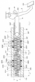
- 1 shows a schematic configuration of a master cylinder of Embodiment 1.
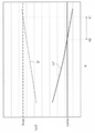
- the relationship between the brake pedal maximum stroke amount S * and the secondary piston required stroke amount Ls * with respect to the pedal ratio K of the first embodiment is shown.
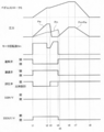
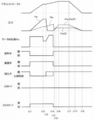
- 6 is a time chart when a failure occurs during by-wire control in the first embodiment. It is a time chart when a failure occurs during by-wire control in a comparative example.
- FIG. 1 shows a schematic configuration including a hydraulic circuit of the brake device 1 (brake system) of the first embodiment.
- the brake device 1 (hereinafter referred to as device 1) is a hydraulic brake device suitable for an electric vehicle.
- the electric vehicle is, for example, a hybrid vehicle provided with a motor generator (rotary electric machine) in addition to an engine (internal combustion engine) or an electric vehicle provided only with a motor generator as a prime mover for driving wheels.
- the apparatus 1 may be applied to a vehicle using only the engine as a driving force source.
- the device 1 supplies brake fluid to a wheel cylinder 8 provided on each wheel FL, FR, RL, RR of the vehicle to generate a brake fluid pressure (wheel cylinder pressure Pw).
- the wheel cylinder 8 may be a cylinder of a hydraulic brake caliper in a disc brake mechanism in addition to a wheel cylinder of a drum brake mechanism.
- the apparatus 1 has brake piping of two systems, that is, a P (primary) system and an S (secondary) system, and employs, for example, an X piping format. In addition, you may employ
- the brake pedal 2 is a brake operation member that receives a brake operation input from the driver (driver).
- the brake pedal 2 is a so-called hanging type, and its base end is rotatably supported by a shaft 201.
- a pad 202 is provided at the tip of the brake pedal 2 as a target to be depressed by the driver.
- One end of the push rod 2a is rotatably connected to the base end side between the shaft 201 and the pad 202 of the brake pedal 2 by a shaft 203.
- the master cylinder 3 is operated by an operation (brake operation) of the brake pedal 2 by the driver, and generates a brake fluid pressure (master cylinder pressure Pm).
- the device 1 does not include a negative pressure type booster that boosts or amplifies the brake operation force (stepping force F of the brake pedal 2) using intake negative pressure generated by the engine of the vehicle. Therefore, the apparatus 1 can be reduced in size.
- the master cylinder 3 is connected to the brake pedal 2 via a push rod 2a, and is supplied with brake fluid from a reservoir tank (reservoir) 4.
- the reservoir tank 4 is a brake fluid source that stores brake fluid, and is a low pressure portion that is opened to atmospheric pressure.
- the bottom side (vertical direction lower side) inside the reservoir tank 4 has a primary hydraulic pressure chamber space 41P, a secondary hydraulic pressure chamber space 41S, and a pump suction space by a plurality of partition members having a predetermined height. It is divided into 42 (defined).
- the master cylinder 3 is a tandem type and includes a primary piston 32P and a secondary piston 32S in series as a master cylinder piston that moves in the axial direction in response to a brake operation.
- Primary piston 32P is connected to push rod 2 ⁇ ⁇ ⁇ a.
- the secondary piston 32S is a free piston type.
- Brake pedal 2 is provided with a stroke sensor 90.
- the stroke sensor 90 detects the amount of displacement of the brake pedal 2 (pedal stroke S).
- the stroke sensor 90 may be provided on the push rod 2a or the primary piston 32P to detect Sp.
- S corresponds to the axial displacement amount (stroke amount) of the push rod 2a or primary piston 32P multiplied by the pedal ratio K of the brake pedal.
- K is a ratio of S to the stroke amount of the primary piston 32P, and is set to a predetermined value. K can be calculated, for example, by the ratio of the distance from the axis 201 to the pad 202 with respect to the distance from the axis 201 to the axis 203.
- the stroke simulator 5 operates according to the driver's brake operation.
- the stroke simulator 5 generates the pedal stroke S when the brake fluid that has flowed out from the inside of the master cylinder 3 flows into the stroke simulator 5 in response to the driver's brake operation.
- the brake fluid supplied from the master cylinder 3 causes the piston 52 of the stroke simulator 5 to operate in the cylinder 50 in the axial direction.
- the stroke simulator 5 produces
- the hydraulic pressure control unit 6 is a braking control unit that can generate the brake hydraulic pressure independently of the brake operation by the driver.
- An electronic control unit (hereinafter referred to as ECU) 100 is a control unit that controls the operation of the hydraulic pressure control unit 6.
- the hydraulic pressure control unit 6 receives supply of brake fluid from the reservoir tank 4 or the master cylinder 3.
- the hydraulic pressure control unit 6 is provided between the wheel cylinder 8 and the master cylinder 3 and can individually supply the master cylinder pressure Pm or the control hydraulic pressure to each wheel cylinder 8.
- the hydraulic pressure control unit 6 includes a motor 7a of the pump 7 and a plurality of control valves (electromagnetic valves 21 and the like) as hydraulic equipment (actuators) for generating a control hydraulic pressure.
- the pump 7 sucks brake fluid from a brake fluid source (reservoir tank 4 or the like) other than the master cylinder 3 and discharges the brake fluid toward the wheel cylinder 8.
- a brake fluid source reservoir tank 4 or the like
- a plunger pump or the like may be used as the pump 7.
- the pump 7 is used in common in both systems, and is rotationally driven by an electric motor (rotary electric machine) 7a as the same drive source.
- the motor 7a for example, a motor with a brush can be used.
- the output shaft of the motor 7a is provided with a resolver that detects its rotational position (rotational angle).
- the solenoid valve 21 or the like opens and closes according to the control signal, and switches the communication state of the oil passage 11 and the like. Thereby, the flow of brake fluid is controlled.
- the hydraulic pressure control unit 6 is provided so that the wheel cylinder 8 can be pressurized by the hydraulic pressure generated by the pump 7 while the communication between the master cylinder 3 and the wheel cylinder 8 is cut off.
- the hydraulic pressure control unit 6 includes hydraulic pressure sensors 91 to 93 that detect hydraulic pressures at various locations such as the discharge pressure of the pump 7 and Pm.
- the ECU 100 receives detection values sent from the resolver, the stroke sensor 90, and the hydraulic pressure sensors 91 to 93, and information related to the running state sent from the vehicle side.
- the ECU 100 performs information processing according to a built-in program based on these various types of information.
- command signals are output to the actuators of the hydraulic pressure control unit 6 in accordance with the processing results to control them. Specifically, the opening / closing operation of the solenoid valve 21 and the like, and the rotation speed of the motor 7a (that is, the discharge amount of the pump 7) are controlled.
- various brake controls are realized by controlling the wheel cylinder pressure Pw of each wheel FL, FR, RL, RR.
- boost control For example, boost control, antilock control, brake control for vehicle motion control, automatic brake control, regenerative cooperative brake control, and the like are realized.
- the boost control assists the brake operation by generating a hydraulic braking force that is insufficient for the driver's brake operation force.
- Anti-lock control suppresses slipping (lock tendency) of the wheels FL, FR, RL, and RR due to braking.
- Vehicle motion control is vehicle behavior stabilization control (hereinafter referred to as ESC) that prevents skidding and the like.
- the automatic brake control is a preceding vehicle following control or the like.
- the regenerative cooperative brake control controls Pw so as to achieve the target deceleration (target braking force) in cooperation with the regenerative brake.
- FIG. 2 is a cross-sectional view passing through the axis of the cylinder 30 of the master cylinder 3 and shows a schematic configuration of the master cylinder 3.
- the x-axis is provided in the direction in which the axis of the cylinder 30 extends.
- the side of the secondary piston 32S with respect to the primary piston 32P is the positive direction side of the x axis.
- the master cylinder 3 is connected to the wheel cylinder 8 via a first oil passage 11 described later.
- the master cylinder 3 is a first hydraulic pressure source capable of generating a hydraulic pressure Pw in the wheel cylinder 8 by generating a hydraulic pressure in the first oil passage 11 with the brake fluid supplied from the reservoir tank 4.
- the cylinder 30 has a bottomed cylindrical shape and includes a cylindrical inner peripheral surface 300.
- the inner peripheral surface 300 is provided with seal grooves 301 and 302 and a supply port 303 for each of the P and S systems.
- the seal grooves 301 and 302 extend in the direction around the axis of the cylinder 30 (circumferential direction).
- the first seal groove 301 is provided on the x-axis positive direction side with respect to the second seal groove 302.
- a replenishment port 303 extending in the circumferential direction is provided so as to be sandwiched between both seal grooves 301 and 302.
- the replenishment port 301 is connected to and communicates with the reservoir tank 4.
- the replenishment port 301P is connected to the primary hydraulic chamber space 41P, and the replenishment port 301S is connected to the secondary hydraulic chamber space 41S.
- the piston 32 of the master cylinder 3 is inserted into the cylinder 30 so as to be movable along the inner peripheral surface 300 in the x-axis direction.
- the diameter of the piston 32 is slightly smaller than the diameter of the cylinder 30 (inner peripheral surface 300).
- Both pistons 32P and 32S have the same diameter and cross-sectional area.
- the cross-sectional area refers to the area of a cross section taken along a plane perpendicular to the x-axis (the axis of each piston 32).
- D be the diameter of both pistons 32P, 32S.
- A is the cross-sectional area of both pistons 32P and 32S.
- A can be calculated from D. D can be equated with the diameter of the master cylinder 3 (cylinder 30).
- Each piston 32 has recesses 321 and 322 extending in the x-axis direction.
- the recess 321 opens to the positive side of the piston 32 in the x-axis direction.
- the recess 322 opens to the negative side of the piston 32 in the x-axis negative direction.
- an oil hole 323 is formed in a radial direction so as to communicate the inner peripheral surface of the recess 321 and the outer peripheral surface of the piston 32.
- the recess 321P is provided with the x-axis negative direction side of the coil spring 33P as a return spring.
- the x-axis positive direction side of the push rod 2a is installed in the recess 322P.
- the recess 321S is provided with the x-axis negative direction side of the coil spring 33S as a return spring.
- the x-axis positive direction side of the coil spring 33P is installed in the recess 322S.
- Primary hydraulic chamber 31P is defined between both pistons 32P and 32S.
- the coil spring 33P is installed in a compressed state.
- a secondary hydraulic chamber 31S is defined between the piston 32S and the positive end of the cylinder 30 in the x-axis direction.
- the coil spring 33S is installed in a compressed state.
- a first oil passage 11 opens in each hydraulic chamber 31P, 31S. The first oil passage 11 is always open to the hydraulic chamber 31 without being blocked by the outer peripheral surface of the piston 32 within a movable range of the piston 32 in the x-axis direction with respect to the cylinder 30.
- the hydraulic chambers 31P and 31S are connected to the hydraulic pressure control unit 6 through the first oil passage 11 and are connected to the wheel cylinder 8.
- the piston seal 34 (corresponding to 341, 342 in the figure) is installed in the seal grooves 301, 302.
- the piston seal 34 is in sliding contact with each piston 32P, 32S (moves while being in contact with each piston 32P, 32S), and seals between the outer peripheral surface of each piston 32P, 32S and the inner peripheral surface 300 of the cylinder 30.
- the piston seal 34 is a well-known cup-shaped seal member (cup seal) having a lip portion on the radially inner side.
- the piston seal 34 allows the flow of brake fluid in one direction and suppresses the flow of brake fluid in the other direction.
- the replenishment port 301 and the hydraulic chamber 31 through the oil hole 323 Communication with is interrupted.
- the first piston seal 341 allows the flow of brake fluid from the replenishment port 301 toward the hydraulic pressure chamber 31, and the flow of brake fluid in the reverse direction.
- the second piston seal 342P suppresses the flow of brake fluid from the supply port 301P toward the brake pedal 2 side.
- the second piston seal 342S suppresses the flow of brake fluid from the primary hydraulic chamber 31P toward the supply port 301S.
- the piston 32 strokes in the positive x-axis direction, and the opening of the oil hole 323 is positioned on the positive x-axis direction side of the first piston seal 341 (the lip). Then, the hydraulic pressure Pm is generated in accordance with the decrease in the volume of the hydraulic pressure chamber 31. Approximately the same Pm is generated in both hydraulic pressure chambers 31P and 31S. As a result, the brake fluid is supplied from the hydraulic chamber 31 to the wheel cylinder 8 through the first oil passage 11. The stroke amount from the initial position of the piston 32 required until the oil hole 323 passes through the first piston seal 341 (the lip portion thereof) and the hydraulic chamber 31 generates Pm is very small. It can be regarded as zero.
- the master cylinder 3 can pressurize the P-type wheel cylinders 8a and 8d through the P-system oil passage (first oil passage 11P) by Pm generated in the primary hydraulic pressure chamber 31P. Further, the master cylinder 3 can pressurize the S system wheel cylinders 8b and 8c through the S system oil passage (first oil passage 11S) by Pm generated in the secondary hydraulic pressure chamber 31S.
- the stroke simulator 5 includes a cylinder 50, a piston 52, and a spring 53.
- FIG. 1 the cross section which passes along the axial center of the cylinder 50 of the stroke simulator 5 is shown.
- the cylinder 50 is cylindrical and has a cylindrical inner peripheral surface.
- the cylinder 50 has a relatively small-diameter piston accommodating portion 501 on the x-axis negative direction side and a relatively large-diameter spring accommodating portion 502 on the x-axis positive direction side.
- a third oil passage 13 (13A) which will be described later, always opens on the inner peripheral surface of the spring accommodating portion 502.
- the piston 52 is installed on the inner peripheral side of the piston accommodating portion 501 so as to be movable in the x-axis direction along the inner peripheral surface thereof.
- the piston 52 is a separation member (partition wall) that separates the inside of the cylinder 50 into at least two chambers (a positive pressure chamber 511 and a back pressure chamber 512).
- a positive pressure chamber 511 is defined on the x-axis negative direction side of the piston 52
- a back pressure chamber 512 is defined on the x-axis positive direction side.
- the positive pressure chamber 511 is a space surrounded by the surface of the piston 52 on the x-axis negative direction side and the inner peripheral surface of the cylinder 50 (piston accommodating portion 501).
- the second oil passage 12 is always open to the positive pressure chamber 511.
- the back pressure chamber 512 is a space surrounded by the surface on the x-axis positive direction side of the piston 52 and the inner peripheral surface of the cylinder 50 (spring accommodating portion 502, piston accommodating portion 501).
- the oil passage 13A always opens to the back pressure chamber 512.
- a piston seal 54 is installed on the outer periphery of the piston 52 so as to extend in the direction around the axis of the piston 52 (circumferential direction).
- the piston seal 54 is in sliding contact with the inner peripheral surface of the cylinder 50 (piston accommodating portion 501), and seals between the inner peripheral surface of the piston accommodating portion 501 and the outer peripheral surface of the piston 52.
- the piston seal 54 is a separation seal member that seals between the positive pressure chamber 511 and the back pressure chamber 512 to separate them liquid-tightly, and complements the function of the piston 52 as the separation member.
- the spring 53 is a coil spring (elastic member) installed in a compressed state in the back pressure chamber 512, and always urges the piston 52 in the x-axis negative direction side.
- the spring 53 is provided so as to be deformable in the x-axis direction, and can generate a reaction force according to the displacement amount (stroke amount) of the piston 52.
- the spring 53 has a first spring 531 and a second spring 532.
- the first spring 531 is smaller in diameter and shorter than the second spring 532, and has a smaller wire diameter.
- the spring constant of the first spring 531 is smaller than that of the second spring 532.
- the first and second springs 531 and 532 are arranged in series via the retainer member 530 between the piston 52 and the cylinder 50 (spring accommodating portion 502).
- the members corresponding to the wheels FL, FR, RL, and RR are appropriately distinguished by adding suffixes a to d at the end of the reference numerals.
- the first oil passage 11 connects the hydraulic chamber 31 of the master cylinder 3 and the wheel cylinder 8.
- the shut-off valve (master cut valve) 21 is a normally open electromagnetic valve (opened in a non-energized state) provided in the first oil passage 11.
- the first oil passage 11 is separated by the shut-off valve 21 into an oil passage 11A on the master cylinder 3 side and an oil passage 11B on the wheel cylinder 8 side.
- Solenoid-in valve (pressurization valve) SOL / V IN25 corresponds to each wheel FL, FR, RL, RR on the wheel cylinder 8 side (oil passage 11B) from the shutoff valve 21 in the first oil passage 11 (oil It is a normally open type solenoid valve provided in the paths 11a to 11d).
- a bypass oil passage 110 is provided in parallel with the first oil passage 11 so as to bypass the SOL / V IN25.
- the bypass oil passage 110 is provided with a check valve (one-way valve or check valve) 250 that allows only the flow of brake fluid from the wheel cylinder 8 side to the master cylinder 3 side.
- the suction oil passage 15 is an oil passage connecting the reservoir tank 4 (pump suction space 42) and the suction portion 70 of the pump 7.
- the discharge oil passage 16 connects the discharge portion 71 of the pump 7 and the shut-off valve 21 and the SOL / V IN25 in the first oil passage 11B.
- the check valve 160 is provided in the discharge oil passage 16 and allows only the flow of brake fluid from the discharge portion 71 side (upstream side) of the pump 7 to the first oil passage 11 side (downstream side).
- the check valve 160 is a discharge valve provided in the pump 7.
- the discharge oil passage 16 is branched downstream of the check valve 160 into a P-system oil passage 16P and an S-system oil passage 16S.
- the oil passages 16P and 16S are connected to the first oil passage 11P of the P system and the first oil passage 11S of the S system, respectively.
- the oil passages 16P and 16S function as communication passages that connect the first oil passages 11P and 11S to each other.
- the communication valve 26P is a normally closed electromagnetic valve (closed in a non-energized state) provided in the oil passage 16P.
- the communication valve 26S is a normally closed electromagnetic valve provided in the oil passage 16S.
- the pump 7 is a second hydraulic pressure source capable of generating a hydraulic pressure in the first oil passage 11 by the brake fluid supplied from the reservoir tank 4 and generating a hydraulic pressure Pw in the wheel cylinder 8.
- the pump 7 is connected to the wheel cylinders 8a to 8d through the communication passage (discharge oil passages 16P and 16S) and the first oil passages 11P and 11S, and brakes the communication passage (discharge oil passages 16P and 16S).
- the foil cylinder 8 can be pressurized by discharging the liquid.
- the first decompression oil passage 17 connects between the check valve 160 and the communication valve 26 in the discharge oil passage 16 and the suction oil passage 15.
- the pressure regulating valve 27 is a normally open type electromagnetic valve as a first pressure reducing valve provided in the first pressure reducing oil passage 17.
- the second decompression oil passage 18 connects the suction oil passage 15 to the wheel cylinder 8 side from the SOL / V IN25 in the first oil passage 11B.
- the solenoid-out valve (pressure reducing valve) SOL / V OUT28 is a normally closed electromagnetic valve as a second pressure reducing valve provided in the second pressure reducing oil passage 18.
- the first pressure reducing oil passage 17 on the suction oil passage 15 side from the pressure regulating valve 27 and the second pressure reduction oil passage 18 on the suction oil passage 15 side from SOL / V OUT28 are partially divided. In common.
- the second oil passage 12 is a branch oil passage branched from the first oil passage 11B and connected to the stroke simulator 5.
- the second oil passage 12 functions as a positive pressure side oil passage connecting the secondary hydraulic pressure chamber 31S of the master cylinder 3 and the positive pressure chamber 511 of the stroke simulator 5 together with the first oil passage 11B. Note that the second oil passage 12 may directly connect the secondary hydraulic pressure chamber 31S and the positive pressure chamber 511 without passing through the first oil passage 11B.
- the third oil passage 13 is a first back pressure side oil passage that connects the back pressure chamber 512 of the stroke simulator 5 and the first oil passage 11.
- the third oil passage 13 branches from between the shutoff valve 21S and SOL / V / IN25 in the first oil passage 11S (oil passage 11B) and is connected to the back pressure chamber 512.
- the stroke simulator in valve SS / V IN23 is a normally closed electromagnetic valve provided in the third oil passage 13.
- the third oil passage 13 is separated by SS / V13IN23 into an oil passage 13A on the back pressure chamber 512 side and an oil passage 13B on the first oil passage 11 side.
- a bypass oil passage 130 is provided in parallel with the third oil passage 13 by bypassing SS / V IN23.
- the bypass oil passage 130 connects the oil passage 13A and the oil passage 13B.
- a check valve 230 is provided in the bypass oil passage 130. The check valve 230 allows the flow of brake fluid from the back pressure chamber 512 side (oil passage 13A) toward the first oil passage 11 side (oil passage 13B) and suppresses the flow of brake fluid in the reverse direction.
- the fourth oil passage 14 is a second back pressure side oil passage connecting the back pressure chamber 512 of the stroke simulator 5 and the reservoir tank 4.
- the fourth oil passage 14 is located between the back pressure chamber 512 and the SS / V IN 23 (oil passage 13A) in the third oil passage 13 and on the suction oil passage 15 side of the suction oil passage 15 (or the pressure regulating valve 27).
- the first decompression oil passage 17 and the second decompression oil passage 18) closer to the suction oil passage 15 than the SOL / V OUT28 are connected.
- the fourth oil passage 14 may be directly connected to the back pressure chamber 512 or the reservoir tank 4.
- the stroke simulator out valve (simulator cut valve) SS / V OUT24 is a normally closed electromagnetic valve provided in the fourth oil passage 14.
- a bypass oil passage 140 is provided in parallel with the fourth oil passage 14 by bypassing SS / V OUT24.
- the bypass oil passage 140 permits the flow of brake fluid from the reservoir tank 4 (suction oil passage 15) side to the third oil passage 13A side, that is, the back pressure chamber 512 side, and suppresses the flow of brake fluid in the reverse direction.
- a check valve 240 is provided.
- the shutoff valve 21, SOL / V IN25, and pressure regulating valve 27 are proportional control valves in which the opening degree of the valve is adjusted according to the current supplied to the solenoid.
- the other valves that is, SS / V23IN23, SS / V OUT24, communication valve 26, and SOL / V OUT28 are two-position valves (on / off valves) in which the opening / closing of the valves is controlled by binary switching. It is also possible to use a proportional control valve as the other valve.
- a hydraulic pressure sensor 91 is provided. Between the shutoff valve 21 and the SOL / V IN25 in the first oil passage 11, there are hydraulic pressure sensors (primary system pressure sensor, secondary system pressure sensor) 92 that detect the hydraulic pressure (wheel cylinder pressure Pw) at this location. Is provided. Between the discharge part 71 (check valve 160) of the pump 7 and the communication valve 26 in the discharge oil passage 16, a hydraulic pressure sensor 93 for detecting the hydraulic pressure (pump discharge pressure) at this point is provided.
- the brake system (first oil passage 11) that connects the hydraulic chamber 31 of the master cylinder 3 and the wheel cylinder 8 with the shut-off valve 21 controlled in the valve opening direction constitutes the first system.
- This first system can realize a pedal force brake (non-boosting control) by generating the wheel cylinder pressure Pw by the master cylinder pressure Pm generated using the pedal force F.
- the brake system suction oil path 15, discharge oil path 16 and the like including the pump 7 and connecting the reservoir tank 4 and the wheel cylinder 8 with the shut-off valve 21 controlled in the valve closing direction is the second Configure the system.
- This second system constitutes a so-called brake-by-wire device that generates Pw by the hydraulic pressure generated using the pump 7, and can realize boost control or the like as brake-by-wire control.
- brake-by-wire control hereinafter simply referred to as “by-wire control”
- the stroke simulator 5 generates an operation reaction force accompanying a driver's brake operation.
- the ECU 100 includes a by-wire control unit 101, a pedaling brake unit 102, and a fail safe unit 103.
- the by-wire control unit 101 closes the shut-off valve 21 and pressurizes the wheel cylinder 8 with the pump 7 according to the brake operation state of the driver. This will be specifically described below.
- the by-wire control unit 101 includes a brake operation state detection unit 104, a target wheel cylinder pressure calculation unit 105, and a wheel cylinder pressure control unit.
- the brake operation state detection unit 104 receives the input of the value detected by the stroke sensor 90, and detects the pedal stroke S as a brake operation amount by the driver. Further, based on S, it is detected whether or not the driver is operating the brake (whether or not the brake pedal 2 is operated).
- a pedal force sensor for detecting the pedal force F may be provided, and the brake operation amount may be detected or estimated based on the detected value. Further, the brake operation amount may be detected or estimated based on the detection value of the hydraulic pressure sensor 91. That is, the brake operation amount used for the control is not limited to S, and other appropriate variables may be used.
- the target wheel cylinder pressure calculation unit 105 calculates a target wheel cylinder pressure Pw *. For example, during boost control, based on the detected pedal stroke S (brake operation amount), S and the driver's required brake fluid pressure (vehicle deceleration requested by the driver) according to a predetermined boost ratio. Calculate Pw * that realizes the ideal relationship (brake characteristics). For example, to calculate Pw * for a predetermined relationship between S and Pw (braking force) realized when a negative pressure booster is activated in a brake device equipped with a normal size negative pressure booster The above ideal relationship.
- the wheel cylinder pressure control unit 106 controls the shutoff valve 21 in the valve closing direction so that the state of the hydraulic pressure control unit 6 can be generated (pressurization control) by the pump 7 (second system). And In this state, hydraulic pressure control (for example, boost control) for controlling each actuator of the hydraulic pressure control unit 6 to realize Pw * is executed. Specifically, the shutoff valve 21 is controlled in the valve closing direction, the communication valve 26 is controlled in the valve opening direction, the pressure regulating valve 27 is controlled in the valve closing direction, and the pump 7 is operated. By controlling in this way, it is possible to send desired brake fluid from the reservoir tank 4 side to the wheel cylinder 8 via the intake oil passage 15, the pump 7, the discharge oil passage 16, and the first oil passage 11. is there.
- hydraulic pressure control for example, boost control
- the brake fluid discharged from the pump 7 flows into the first oil passage 11B through the discharge oil passage 16.
- each wheel cylinder 8 is pressurized. That is, the wheel cylinder 8 is pressurized using the hydraulic pressure generated in the first oil passage 11B by the pump 7.
- a desired braking force can be obtained by feedback control of the rotation speed of the pump 7 and the valve opening state (opening degree, etc.) of the pressure regulating valve 27 so that the detection value of the hydraulic pressure sensor 92 approaches Pw *. it can. That is, Pw can be adjusted by controlling the valve opening state of the pressure regulating valve 27 and appropriately leaking brake fluid from the discharge oil passage 16 to the first oil passage 11 to the intake oil passage 15 through the pressure regulating valve 27. .
- Pw is controlled by changing not the rotational speed of the pump 7 (motor 7a) but the valve opening state of the pressure regulating valve 27.
- the shut-off valve 21 in the valve closing direction and shutting off the master cylinder 3 side and the wheel cylinder 8 side, it becomes easy to control Pw independently of the driver's brake operation.
- SS / VSSOUT24 is controlled in the valve opening direction.
- the back pressure chamber 512 of the stroke simulator 5 communicates with the suction oil passage 15 (reservoir tank 4) side.
- the brake fluid is discharged from the master cylinder 3, and when this brake fluid flows into the positive pressure chamber 511 of the stroke simulator 5, the piston 52 is activated.
- a pedal stroke Sp is generated.
- Brake fluid having the same amount as that flowing into the positive pressure chamber 511 flows out from the back pressure chamber 512.
- the brake fluid is discharged to the suction oil passage 15 (reservoir tank 4) through the third oil passage 13A and the fourth oil passage 14.
- the fourth oil passage 14 need only be connected to a low-pressure portion through which brake fluid can flow, and need not necessarily be connected to the reservoir tank 4.
- an operation reaction force (pedal reaction force) acting on the brake pedal 2 is generated by the force by which the hydraulic pressure of the spring 53 of the stroke simulator 5 and the back pressure chamber 512 presses the piston 52. That is, the stroke simulator 5 generates a characteristic of the brake pedal 2 (FS characteristic that is a relation of S to F) during the by-wire control.
- the wheel cylinder pressure control unit 104 basically performs boost control during normal braking in which braking force corresponding to the driver's braking operation is generated in the front and rear wheels FL, FR, RL, RR.
- boost control SOL / V IN25 of each wheel FL, FR, RL, RR is controlled in the valve opening direction, and SOL / V OUT28 is controlled in the valve closing direction.
- the pressure regulating valve 27 is proportionally controlled in the valve closing direction (the degree of opening is feedback controlled).
- the communication valve 26 is controlled in the valve opening direction, the rotational speed command value Nm * of the motor 7a is set to a predetermined constant value, and the pump 7 is operated.
- SS / V IN23 is deactivated (controlled in the valve closing direction) and SS / V OUT24 is activated (controlled in the valve opening direction).
- the pedal force brake unit 102 opens the shut-off valve 21 and pressurizes the wheel cylinder 8 by the master cylinder 3.
- the hydraulic pressure control unit 6 is brought into a state in which the wheel cylinder pressure Pw can be generated by the master cylinder pressure Pm (first system), thereby realizing a pedaling brake.
- the stroke simulator 5 is deactivated in response to the driver's brake operation.
- the brake fluid is efficiently supplied from the master cylinder 3 toward the wheel cylinder 8. Therefore, it is possible to suppress a decrease in Pw generated by the driver with the pedal effort F.
- the pedal force brake unit 102 deactivates all the actuators in the hydraulic pressure control unit 6.
- SS / V / IN23 may be controlled in the valve opening direction.
- the fail safe unit 103 detects the occurrence of an abnormality (failure or failure) in the device 1 (brake system). For example, a failure of an actuator (pump 7 or motor 7a, pressure regulating valve 27, etc.) in the hydraulic pressure control unit 6 is detected based on a signal from the brake operation state detection unit 104 or a signal from each sensor. Alternatively, an abnormality of the on-vehicle power supply (battery) that supplies power to the apparatus 1 or the ECU 100 is detected.
- fail-safe unit 103 detects the occurrence of an abnormality during by-wire control, it operates pedal force brake unit 102 to switch from by-wire control to pedal force brake.
- the shut-off valve 21 is a normally open valve. For this reason, when the power supply fails, the shut-off valve 21 is opened, so that it is possible to automatically realize the pedal effort braking.
- SS / V OUT24 is a normally closed valve. For this reason, the stroke simulator 5 is automatically deactivated by closing SS / V OUT24 when the power supply fails.
- the communication valve 26 is a normally closed type. For this reason, when the power failure occurs, the brake hydraulic pressure systems of both systems are made independent from each other, and the wheel cylinder can be pressurized by the pedaling force F in each system separately. As a result, fail-safe performance can be improved.
- the amount of brake fluid that can be stored in the primary hydraulic chamber 31P in other words, the amount of fluid that can be supplied from the primary hydraulic chamber 31P (that can flow out) is Vp *.
- Lp be the stroke amount of the primary piston 32P relative to the secondary piston 32S.
- Lp * is Lp required to secure the required stroke amount of the primary piston, that is, Vp *.
- Lp * is the maximum stroke amount (relative to the secondary piston 32S) of the primary piston 32P.
- Vs * be the amount of brake fluid that can be stored in the secondary hydraulic chamber 31S, in other words, the amount of brake fluid that can be supplied from the secondary hydraulic chamber 31S.
- Vs * is the amount of brake fluid in the secondary hydraulic chamber 31S when the master cylinder 3 is not in operation, and the secondary fluid during control by the by-wire control unit 101 (hereinafter referred to as “by-wire control”) and during operation of the pedal brake unit 102.
- the stroke amount of the secondary piston 32S relative to the cylinder 30 is Ls. Let Ls * be Ls necessary to secure the required stroke amount of the secondary piston, that is, Vs *. Specifically, Ls * is the maximum stroke amount (relative to the cylinder 30) of the secondary piston 32S.
- Vss The maximum amount of absorbed fluid of the stroke simulator 5, that is, the amount of brake fluid that can be absorbed by the positive pressure chamber 511 is Vss.
- Vss is the amount of brake fluid that flows into the positive pressure chamber 511 before the piston 52 makes a maximum stroke from the initial position.
- the volume of the positive pressure chamber 511 can be regarded as zero. Therefore, Vss is the amount of brake fluid in the positive pressure chamber 511 when the piston 52 makes the maximum stroke.
- Vf be the amount of brake fluid that must be supplied.
- the pedal force brake unit 102 is operated to ensure the braking force.
- Vf is the amount of brake fluid required for that purpose. For example, if it is necessary to generate a deceleration of the vehicle of 0.65G when the pedaling force F is 500N, the wheel cylinder pressure necessary to generate this 0.65G is set to the target wheel cylinder pressure (the pedaling force brake target pressure at the time of failure).
- Vf can be set based on this Pw * and the hydraulic pressure-fluid quantity characteristic of the wheel cylinder 8. It should be noted that the magnitude of Vf may be different between the P system side and the S system side, such as when the front and rear piping type is used.
- Vp * is set so as to satisfy the following formula (1) with respect to Vf.
- Equation 1 Vp * ⁇ Vf (1)
- Vp * is set so as to satisfy the relationship satisfying the following formula (2).
- Vp * Vf (2)
- A is a cross-sectional area of the piston 32.
- Vp * Lp * ⁇ A (3) Therefore, Lp * and A that satisfy the above equation (2) are set.
- Lp * Vp * / A (4) From the above equations (2) and (4), the following equation (5) is established.
- Vs * is set so as to satisfy the following expression (7) with respect to Vss.
- Vs * is set so that Vss and Vf satisfy the following expression (8).
- Vs * is set so as to satisfy the relationship that satisfies the following formula (9).
- Vs * Vss + Vf (9)
- the secondary hydraulic chamber 31S has a volume corresponding to the sum of Vss and Vf.
- the following formula (10) holds.
- Vs * Ls * ⁇ A (10) Therefore, Ls * and A that satisfy the above equations (9) and (10) are set. For example, regarding Ls *, the following equation (11) holds.
- Ls * Vs * / A (11)
- Ls * can be set by the following formula (12).
- Vss / A is the stroke amount of the secondary piston 32S necessary for supplying Vss to the positive pressure chamber 511 during the by-wire control, and is the maximum stroke amount of the secondary piston 32S during the by-wire control.
- Equation 16 Vs *> Vp * (16) That is, Vs * is greater than Vp * by Vss.
- equation (17) is established.
- Equation 17 Ls *> Lp * (17) That is, since the first oil passage 11A is not connected to the stroke simulator 5 on the P system side, the necessary stroke amount of the piston 32 is smaller than that on the S system side.
- Sn be the maximum stroke amount of the brake pedal 2 during the by-wire control.
- Sn is a pedal stroke necessary for satisfying a predetermined pedal feeling during the by-wire control, and is set to a predetermined constant value that does not depend on the pedal ratio K.
- Vss is determined from Sn, K, A by the following formula (18).
- Vss (Sn / K) ⁇ A (18) That is, Vss is the amount of liquid that flows out from the secondary hydraulic chamber 31S in order to realize Sn during the by-wire control, in other words, the amount of liquid that the stroke simulator 5 is required to absorb. From the above equations (13) and (18), the following equation (19) is established.
- Lsn Sn / K (19)
- Vs * Vss + Vf.
- FIG. 3 shows the relationship between S * and Ls * with respect to K.
- the maximum design value of the pedal stroke S is Smax.
- FIG. 4 is a time chart showing an example of temporal changes in the pedal stroke S, each pressure, and the operating state of each actuator when one of the actuators (pressure regulating valve 27) fails during the by-wire control in the apparatus 1. It is. At time t1, the driver starts the brake operation. From time t1 to t2, the brake pedal 2 is depressed. During the brake operation, the ECU 100 executes the by-wire control by the by-wire control unit 101. That is, when the brake operation state detection unit 104 detects a brake operation, the wheel cylinder pressure control unit 106 controls the shut-off valve 21 in the valve closing direction and SS / V OUT24 in the valve opening direction.
- the brake fluid accommodated in the secondary hydraulic pressure chamber 31S is supplied to the stroke simulator 5 (positive pressure chamber 511).
- the stroke simulator 5 operates and the pedal stroke S increases from zero.
- the master cylinder pressure Pm pressure in the primary hydraulic pressure chamber 31P and the secondary hydraulic pressure chamber 31S
- the target wheel cylinder pressure calculation unit 105 calculates the target wheel cylinder pressure Pw *.
- the wheel cylinder pressure control unit 106 operates the pump 7 (keeps the rotational speed Nm of the motor 7a at a predetermined constant value), controls the communication valve 26 in the valve opening direction, and regulates the pressure. Proportionally controls 27 in the valve closing direction.
- the pressure regulating valve 27 fails at time t3.
- the command to the pressure regulating valve 27 indicated by the broken line is the valve closing direction (proportional control)
- the actual operation of the pressure regulating valve 27 indicated by the solid line is the valve opening direction (open sticking).
- the brake fluid discharged from the pump 7 is discharged through the first decompression oil passage 17.
- Pw cannot be maintained at Pw *.
- the driver further depresses the brake pedal 2 in order to increase the braking force.
- S and Pm increase.
- the fail safe unit 103 detects the occurrence of an abnormality (failure of the pressure regulating valve 27) and switches from the by-wire control to the pedal force brake. That is, times t3 to t4 are times necessary for detecting an abnormality.
- fail-safe unit 103 deactivates all actuators and activates pedal force brake unit 102.
- Shut-off valve 21 opens, SS / V / OUT24 closes, and communication valve 26 closes.
- the brake fluid accommodated in the primary hydraulic chamber 31P has a first oil passage according to an increase in the stroke amount Lp of the primary piston 32P (a reduction in the volume of the primary hydraulic chamber 31P).
- Vs * is set to be larger than Vss as shown in the above equation (7). Therefore, even if the stroke amount of the piston 52 of the stroke simulator 5 becomes maximum (even if it is a full stroke) from time t3 to t4, brake fluid that can flow out remains in the secondary hydraulic pressure chamber 31S.
- the brake fluid is not supplied to the stroke simulator 5 (positive pressure chamber 511) but via the first oil passage 11S in response to an increase in the stroke amount Ls of the secondary piston 32S (reduction in the volume of the secondary hydraulic chamber 31S). Supplied to S-type wheel cylinders 8b and 8c.
- the pressures of the wheel cylinders 8a and 8d that is, the wheel cylinder pressure Pw (P) of the P system
- the pressures of the wheel cylinders 8b and 8c that is, the wheel cylinder pressure Pw (S) of the S system
- S increases as the stroke amount of the primary piston 32P with respect to the cylinder 30 increases.
- Pm the pressure in the primary hydraulic chamber 31P and the secondary hydraulic chamber 31S
- Pm the pressure in the primary hydraulic chamber 31P and the secondary hydraulic chamber 31S
- Pm increases with a value equivalent to Pw.
- Vp * is set to Vf as shown in equation (2) above. Therefore, at time t4, regardless of the stroke amount of the piston 52 of the stroke simulator 5, the amount of fluid that can be supplied from the primary hydraulic chamber 31P to the wheel cylinders 8a, 8d is Vf.
- Vs * is set to Vss + Vf as in the above equation (9). Therefore, even if the stroke amount of the piston 52 becomes maximum from time t3 to t4, the amount of liquid that can be supplied from the secondary hydraulic pressure chamber 31S to the wheel cylinders 8b and 8c at time t4 is Vf.
- both Pw (P) and Pw (S) increase, and at time t6 when Lp and Ls become Lp * and Ls *, respectively, Pw (P) and Pw (S) are at the time of failure.
- Pw (P) and Pw (S) are held at Pw * as the brake fluid cannot be supplied from the hydraulic chamber 31 to the wheel cylinder 8.
- S is held at the maximum stroke amount S * at the time of failure.
- the driver starts to depress the brake pedal 2.
- Pw (P) and Pw (S) start to decrease at a value equivalent to Pm.
- the brake fluid stored in the primary hydraulic pressure chamber 31P does not flow out to the first oil passage 11. (The volume of the primary hydraulic chamber 31P does not change).
- the brake fluid stored in the secondary hydraulic chamber 31S flows out into the first oil passage 11A and flows into the positive pressure chamber 511 of the stroke simulator 5 through the second oil passage 12 (the volume of the secondary hydraulic chamber 31S decreases). To do).
- the positive pressure chamber 511 absorbs the brake fluid from the secondary hydraulic pressure chamber 31S, so that the stroke simulator 5 operates and ensures pedal feeling.
- the master cylinder 3 and the wheel cylinder 8 are made to communicate with each other, and the hydraulic pressure can be generated in the wheel cylinder 8 by the driver's brake operation force. To do. Thereby, a required braking force is ensured.
- the brake fluid accommodated in the primary hydraulic chamber 31P flows into the wheel cylinders 8a and 8d via the first oil passage 11P.
- the brake fluid stored in the secondary hydraulic chamber 31S flows into the wheel cylinders 8b and 8c through the first oil passage 11S.
- the piston 52 of the stroke simulator 5 stops at or near the position when switching from the by-wire control to the pedaling brake, and flows into the positive pressure chamber 511 from the secondary hydraulic chamber 31S (during the by-wire control).
- the brake fluid is stored. Even if the driver depresses the brake pedal 2 to generate the wheel cylinder pressure Pw (braking force) in this state, only the amount of the brake fluid that has already flowed into the positive pressure chamber 511 (corresponding to the stroke of the piston 52). The amount of liquid that can be supplied from the secondary hydraulic chamber 31S to the wheel cylinders 8b and 8c is reduced.
- the piping system (S system) provided with the stroke simulator 5 has a positive pressure according to the amount of brake operation performed so far.
- the amount of brake fluid available for pressurizing the wheel cylinder 8 is reduced by the amount of fluid absorbed in the chamber 511. Therefore, there is a possibility that sufficient braking force cannot be obtained when an abnormality occurs.
- the amount of fluid that can be supplied from the secondary fluid pressure chamber 31S (the amount of brake fluid that can flow out from the secondary fluid pressure chamber 31S during the by-wire control and the pedaling brake) Vs as expressed by the above equation (7).
- the brake fluid can be supplied from the secondary hydraulic pressure chamber 31S to the wheel cylinders 8b and 8c in accordance with the depression operation of the brake pedal 2 by the driver.
- the wheel cylinders 8b, 8c can be pressurized by the master cylinder 3 even when switching to the pedaling brake, so that a sufficient braking force can be provided when an abnormality occurs. Can be obtained.
- FIG. 5 is a time chart similar to FIG. 4 in the comparative example.
- Vp * is set to Vf.
- Vs * is set to be larger than Vss and smaller than Vss + Vf.
- Times t11 to t15 are the same as t1 to t5 in FIG.
- Vs * is set to be smaller than Vss + Vf. Therefore, if the stroke amount of the piston 52 of the stroke simulator 5 exceeds a predetermined value (for example, a value close to the maximum stroke amount) from time t13 to t14, it can be supplied from the secondary hydraulic pressure chamber 31S to the wheel cylinders 8b and 8c at time t14.
- a predetermined value for example, a value close to the maximum stroke amount
- the amount of liquid that can be supplied from the primary hydraulic chamber 31P to the wheel cylinders 8a and 8d at time t14 is Vf.
- Pw (P) increases after time t14 and continues to increase after time t151.
- Pw (P) becomes the pedal effort brake target pressure Pw * at the time of failure.
- Pw (P) is held at Pw * as brake fluid cannot be supplied from the primary hydraulic chamber 31P to the wheel cylinders 8a and 8d.
- S is held as primary piston 32P cannot stroke any more.
- the driver starts to depress the brake pedal 2.
- Pw (P) starts decreasing at a value equivalent to the pressure in the primary hydraulic pressure chamber 31P.
- Pw (P) decreases to Pw (S).
- Pw (P) and Pw (S) decrease while taking equivalent values, and become zero at time t18.
- the fluid amount Vs * that can be supplied from the secondary hydraulic chamber 31S is set to the target wheel by the pedal force brake unit 102 as shown in the above equation (9). It is set to the total value of the liquid volume Vf and Vss necessary for generating the cylinder pressure Pw *. Therefore, if an abnormality occurs while the driver operates the brake and Pw is generated by the by-wire control, even if the positive pressure chamber 511 absorbs the brake fluid to the maximum extent, the secondary hydraulic pressure chamber 31S The fluid volume Vf necessary to generate Pw * by the pedal force brake remains inside.
- Vs * may be larger than the total value of Vf and Vss as in the above equation (8). In this embodiment, Vs * is the total value of Vf and Vss.
- Vp * may be equal to or higher than Vs *.
- Vp * is set to be smaller than Vs * as shown in the above equation (16). Therefore, since the sum of Vp * and Vs *, that is, the sum of the volumes of the hydraulic chambers 31P and 31S (corresponding to Vp * and Vs *, respectively) is suppressed, the volume of the master cylinder 3 as a whole is increased. It is suppressed. In other words, when Vs * (the volume of the secondary hydraulic chamber 31S corresponding to) is set as described above, Vp * (the volume of the primary hydraulic chamber 31P corresponding to) is set smaller than Vs *.
- Vp * may be larger than Vf.
- Vp * is set to Vf as in the above equation (2). Therefore, the volume of Vp * (corresponding to the primary hydraulic pressure chamber 31P) is suppressed to the minimum that can secure the necessary liquid amount Vf. For this reason, the increase in the volume of the master cylinder 3 as a whole can be more effectively suppressed.
- the diameter (cross-sectional area) of the primary hydraulic chamber 31P may be smaller than the diameter (cross-sectional area) of the secondary hydraulic chamber 31S.
- the maximum stroke amount Lp * of the primary piston 32P is made smaller than the maximum stroke amount Ls * of the secondary piston 32S as shown in the above equation (17). Therefore, there is no need to change the diameters of the hydraulic chamber 31 and the piston 32 between the P system and the S system, so that Vp * can be set to be less than Vs * more easily.
- the primary piston 32P and the secondary piston 32S have the same cross-sectional area A. Therefore, the piston 32 and the cylinder 30 can be manufactured more easily.
- Lp * smaller than Ls * an increase in the axial length (x-axis direction dimension) of the master cylinder 3 can be suppressed. By suppressing the increase in the axial length, the piston 32 and the cylinder 30 can be manufactured more easily.
- the piping system including the stroke simulator 5 in the apparatus 1 is the S system.
- the piston 32 of the master cylinder 3 operates corresponding to the stroke S of the brake pedal 2.
- the primary piston 32P operates in conjunction with the brake pedal 2.
- the secondary piston 32S defines the secondary hydraulic chamber 31S, and defines the primary hydraulic chamber 31P together with the primary piston 32P.
- the primary hydraulic chamber 31P is connected to the wheel cylinders 8a and 8d via the first oil passage 11P to which the stroke simulator 5 is not connected.
- the secondary hydraulic pressure chamber 31S is connected to the positive pressure chamber 511 of the stroke simulator 5 through the second oil passage 12.
- the secondary hydraulic chamber 31S is connected to the wheel cylinders 8b and 8c through the first oil passage 11S to which the stroke simulator 5 is connected.
- the piping system provided with the stroke simulator 5 is not limited to the S system, and may be a P system. In this case, the secondary hydraulic pressure chamber 31S is read as the primary hydraulic pressure chamber 31P.
- Vss is set to a value obtained by multiplying Sn / K by A. That is, the positive pressure chamber 511 of the stroke simulator 5 is provided so as to be able to absorb (Sn / K) ⁇ A liquid amount. Therefore, during the by-wire control, the (Sn / K) ⁇ A liquid amount can flow out from the secondary hydraulic chamber 31S. In other words, the brake pedal 2 can stroke by Sn. Therefore, a predetermined pedal feeling can be satisfied during the by-wire control.
- S * is set to a value obtained by multiplying the total value of Vs * / A and Vf / A by K.
- S * is set to a value obtained by multiplying the total value of Lp * and Ls * by K (or more).
- S * is set in this way, the required stroke amount Lp * of the primary piston 32P and the required stroke amount Ls * of the secondary piston 32S can be realized.
- Lp * is set to Vf / A as in the above equation (5), even if an abnormality occurs during the by-wire control, the necessary braking force in the P system can be generated by the pedal force brake.
- a brake device to which the present invention is applied includes a mechanism (stroke simulator) for simulating a reaction force of a brake operation, and disconnects communication between a master cylinder and a wheel cylinder, except for the master cylinder.
- the hydraulic pressure source is not limited to a pump but may be an accumulator or the like.
- the hydraulic circuit for controlling the wheel cylinder pressure, the configuration of the actuator, and the operation method of each actuator are not limited to those of the embodiment, and can be appropriately changed.
Landscapes
- Engineering & Computer Science (AREA)
- Transportation (AREA)
- Mechanical Engineering (AREA)
- Physics & Mathematics (AREA)
- Fluid Mechanics (AREA)
- Electromagnetism (AREA)
- Regulating Braking Force (AREA)
- Transmission Of Braking Force In Braking Systems (AREA)
- Braking Systems And Boosters (AREA)
- Valves And Accessory Devices For Braking Systems (AREA)
Abstract
Description
まず、構成を説明する。図1は、実施例1のブレーキ装置1(ブレーキシステム)の、液圧回路を含む概略構成を示す。ブレーキ装置1(以下、装置1という。)は、電動車両に好適な液圧式ブレーキ装置である。電動車両は、車輪を駆動する原動機として、エンジン(内燃機関)のほかモータジェネレータ(回転電機)を備えたハイブリッド車や、モータジェネレータのみを備えた電気自動車等である。なお、エンジンのみを駆動力源とする車両に装置1を適用してもよい。装置1は、車両の各車輪FL、FR、RL、RRに設けられたホイルシリンダ8にブレーキ液を供給してブレーキ液圧(ホイルシリンダ圧Pw)を発生させる。このPwにより摩擦部材を移動させ、摩擦部材を車輪側の回転部材に押付けることで、摩擦力を発生させる。これにより、各車輪FL、FR、RL、RRに液圧制動力を付与する。ここで、ホイルシリンダ8は、ドラムブレーキ機構のホイルシリンダのほか、ディスクブレーキ機構における油圧式ブレーキキャリパのシリンダであってもよい。装置1は、2系統すなわちP(プライマリ)系統及びS(セカンダリ)系統のブレーキ配管を有しており、例えばX配管形式を採用している。なお、前後配管等、他の配管形式を採用してもよい。以下、P系統に対応して設けられた部材とS系統に対応する部材とを区別する場合は、それぞれの符号の末尾に添字P,Sを付す。
本実施例では、下記式(2)を満たす関係となるようにVp*を設定する。(数2)Vp*=Vf ・・・(2)
言換えると、プライマリ液圧室31Pは、Vfに対応する容積を備える。また、下記式(3)が成り立つ(Aはピストン32の断面積)。
(数3)Vp*=Lp*×A ・・・(3)
よって、上記式(2)を満足するようなLp*とAを設定する。例えばLp*についてみると、下記式(4)が成り立つ。
(数4)Lp*=Vp*/A ・・・(4)
上記式(2)(4)から、下記式(5)が成り立つ。
(数5)Lp*=Vf/A ・・・(5)
バイワイヤ制御中に失陥が発生した場合、踏力ブレーキ部102を作動させてプライマリ液圧室31PからP系統のホイルシリンダ8a,8dへブレーキ液量Vfを供給する。これにより制動力を確保する。Vf/Aは、そのために必要となるプライマリピストン32Pのストローク量である。このストローク量をLpfとすると、下記式(6)が成り立つ。
(数6)Lp*=Lpf ・・・(6)
具体的には、Vss,Vfに対し下記式(8)を満たす関係となるようにVs*を設定する。
(数8)Vs*≧Vss+Vf ・・・(8)
本実施例では、下記式(9)を満たす関係となるようにVs*を設定する。(数9)Vs*=Vss+Vf ・・・(9)
言換えると、セカンダリ液圧室31Sは、VssとVfとの合計に対応する容積を備える。一方、下記式(10)が成り立つ。
(数10)Vs*=Ls*×A ・・・(10)
よって、上記式(9)(10)を満足するようなLs*とAを設定する。例えばLs*についてみると、下記式(11)が成り立つ。
(数11)Ls*=Vs*/A ・・・(11)
上記式(9)(11)から、Ls*は、下記式(12)により設定できる。
(数12)Ls*=(Vss+Vf)/A
=Vss/A+Vf/A ・・・(12)
Vss/Aは、バイワイヤ制御時に正圧室511へVssを供給するために必要なセカンダリピストン32Sのストローク量であり、バイワイヤ制御時におけるセカンダリピストン32Sの最大ストローク量である。このストローク量をLsnとすると、下記式(13)が成り立つ。
(数13)Lsn=Vss/A ・・・(13)
バイワイヤ制御中に失陥が発生した場合、踏力ブレーキ部102を作動させてセカンダリ液圧室31SからS系統のホイルシリンダ8b,8cへブレーキ液量Vfを供給する。これにより制動力を確保する。Vf/Aは、そのために追加的に必要となるセカンダリピストン32Sのストローク量である。このストローク量をLsfとすると、下記式(14)が成り立つ。
(数14)Lsf=Vf/A ・・・(14)
上記式(12)(13)(14)から、下記式(15)が成り立つ。
(数15)Ls*=Lsn+Lsf ・・・(15)
(数16)Vs*>Vp* ・・・(16)
すなわち、Vssの分だけ、Vs*がVp*よりも多い。上記式(4)(11)(16)より、下記式(17)が成り立つ。
(数17)Ls*>Lp* ・・・(17)
すなわち、P系統側は、第1油路11Aがストロークシミュレータ5に接続されていないため、その分だけ、必要なピストン32のストローク量がS系統側よりも小さい。
(数18)Vss=(Sn/K)×A ・・・(18)
すなわち、Vssは、バイワイヤ制御時において、Snを実現するためにセカンダリ液圧室31Sから流出する液量、言換えると、ストロークシミュレータ5が吸収することを要求される液量である。上記式(13)(18)から、下記式(19)が成り立つ。
(数19)Lsn=Sn/K ・・・(19)
(数20)S*=Sn+Sf ・・・(20)
S*は、Vs*の全てをセカンダリ液圧室31Sから吐出可能なストローク量に設定する必要があるため、Vs*,Vf,K,Aから下記式(21)により決定する。
(数21)S*≧(Vs*/A+Vf/A)×K ・・・(21)
上記式(11)から、Vs*/AはLs*に相当する。上記式(5)から、Vf/AはLp*に相当する。よって、下記式(22)が成り立つ。
(数22)S*≧(Lp*+Ls*)×K ・・・(22)
すなわち、Lp*とLs*との合計値にKを乗じた値は、マスタシリンダピストン32の必要ストローク量Lp*,Ls*を実現するために必要なブレーキペダル2のストローク量(必要ペダルストローク)であり、S*をこの値以上に設定する。本実施例では、下記式(23)を満たす関係となるように、S*を設定する。
(数23)S*=(Lp*+Ls*)×K ・・・(23)
(数24)S*=(Vss/A+Vf/A+Vf/A)×K
=(Vss/A)×K+(2Vf/A)×K ・・・(24)
右辺第1式についてみると、上記式(13)から、Vss/AがLsnに相当する。上記式(14)から、Vf/Aの一方がLsfに相当する。上記式(5)(6)から、Vf/Aの他方がLpfに相当する。右辺第2式についてみると、上記式(18)から、(Vss/A)×KがSnに相当する。よって、上記式(20)から、(2Vf/A)×KがSfに相当する。上記式(5)(6)(14)から、下記式(25)が成り立つ。
(数25)Sf=(2Vf/A)×K =(Lsf+Lpf)×K ・・・(25)
2Vf/AないしLsf+Lpfは、踏力ブレーキ部102による制動力を確保するために追加的に必要となるマスタシリンダピストン32(プライマリピストン32P及びセカンダリピストン32S)のストローク量である。
(数26)S*=Sn+(2Vf/A)×K ・・・(26)
すなわち、Sn,Vf,Aを所与としたとき、S*はKに応じて変化する。Kが大きいときは、Kが小さいときよりも、S*が大きくなる。S*=SmaxとなるときのKをK1とすると、Smax≧S*の要請から、K≦K1である必要がある。また、上記式(14)(15)(19)から、下記式(27)が成り立つ。
(数27)Ls*=Sn/K+Vf/A ・・・(27)
すなわち、Sn,Vf,Aを所与としたとき、Ls*はKに応じて変化する。Kが大きいときは、Kが小さいときよりも、Ls*が小さくなる。Lsmax=Ls*となるときのKをK2とすると、Lsmax≧Ls*の要請から、K≧K2である必要がある。よって、Kの成立範囲はK2からK1までとなる。K2≦K≦K1を満たすようにKを設定する。
以上、本発明を実現するための形態を、実施例に基づいて説明してきたが、本発明の具体的な構成は実施例に限定されるものではなく、発明の要旨を逸脱しない範囲の設計変更等があっても、本発明に含まれる。例えば、本発明が適用されるブレーキ装置(ブレーキシステム)は、ブレーキ操作の反力を模擬するための機構(ストロークシミュレータ)を備えると共に、マスタシリンダとホイルシリンダとの連通を遮断し、マスタシリンダ以外の液圧源によりホイルシリンダを加圧することが可能なものであればよく、実施例のものに限らない。例えば上記液圧源は、ポンプに限らず、アキュムレータ等であってもよい。また、ホイルシリンダ圧を制御するための液圧回路及びアクチュエータの構成や各アクチュエータの作動方法は、実施例のものに限らず適宜変更可能である。
以上、本発明の幾つかの実施形態のみを説明したが、本発明の新規の教示や利点から実質的に外れることなく例示の実施形態に、多様な変更または改良を加えることが可能であることが当業者には容易に理解できるであろう。従って、その様な変更または改良を加えた形態も本発明の技術的範囲に含むことを意図する。上記実施形態を任意に組み合わせてもよい。
特開2010-83411号公報(特許文献1)の明細書、特許請求の範囲、図面及び要約書を含む全ての開示は、参照により全体として本願に組み込まれる。
2 ブレーキペダル(ブレーキ操作部材)
21 遮断弁(バルブ)
3 マスタシリンダ
31P プライマリ液圧室(第2の室)
31S セカンダリ液圧室(第1の室)
32P プライマリピストン
32S セカンダリピストン
5 ストロークシミュレータ
52 ピストン
511 正圧室
7 ポンプ(液圧源)
8 ホイルシリンダ
11 第1油路(油路)
12 第2油路(分岐油路)
101 バイワイヤ制御部
102 踏力ブレーキ部
Claims (17)
- ブレーキ装置(1)であって、
マスタシリンダ(3)とホイルシリンダ(8)との間を接続する油路(11)と、
前記油路の連通状態を切り替えるバルブ(21)と、
運転者のブレーキ操作状態に応じて、前記バルブを閉じ、前記マスタシリンダとは別に設けられた液圧源(7)により前記ホイルシリンダを加圧するバイワイヤ制御部(101)と、
前記バルブを開け、前記マスタシリンダにより前記ホイルシリンダを加圧する踏力ブレーキ部(102)と、
前記油路のうち前記マスタシリンダと前記バルブとの間に接続し、内部に形成された正圧室(511)の容積が増減することでブレーキ操作反力を生成するストロークシミュレータ(5)とを備え、
前記バイワイヤ制御部による制御時に、前記マスタシリンダの第1の室(31S)内に収容されたブレーキ液が前記正圧室に流れ込み、
前記第1の室から供給可能な液量は、前記正圧室が吸収可能な液量よりも多いことを特徴とするブレーキ装置。 - 請求項1に記載のブレーキ装置において、
前記第1の室から供給可能な液量は、前記正圧室が吸収可能な液量と、前記踏力ブレーキ部により目標ホイルシリンダ圧を発生させるために必要な液量との合計値以上であることを特徴とするブレーキ装置。 - 請求項1に記載のブレーキ装置において、
前記マスタシリンダは、前記第1の室と区画され、前記ストロークシミュレータが接続しない前記油路を介して前記ホイルシリンダに接続する第2の室を備え、
前記第2の室から供給可能な液量は、前記第1の室から供給可能な液量よりも少ないことを特徴とするブレーキ装置。 - 請求項3に記載のブレーキにおいて、
前記第2の室から供給可能な液量は、前記踏力ブレーキ部により目標ホイルシリンダ圧を発生させるために必要な液量であることを特徴とするブレーキ装置。 - 請求項1に記載のブレーキ装置において、
前記マスタシリンダは、ブレーキ操作部材のストロークに対応して作動し、
前記踏力ブレーキ部の作動時を含めた前記ブレーキ操作部材の最大ストローク量は、前記第1の室から供給可能な液量を前記マスタシリンダの断面積で除した値と、前記踏力ブレーキ部により目標ホイルシリンダ圧を発生させるために必要な液量を前記マスタシリンダの断面積で除した値との合計値に、所定の比率を乗じた値に設定されていることを特徴とするブレーキ装置。 - 請求項1に記載のブレーキ装置において、
前記マスタシリンダは、ブレーキ操作部材のストロークに対応して作動し、
前記正圧室が吸収可能な液量は、前記バイワイヤ制御部による制御時における前記ブレーキ操作部材の最大ストローク量を所定の比率で除した値に、前記マスタシリンダの断面積を乗じた値であることを特徴とするブレーキ装置。 - 請求項1に記載のブレーキ装置において、
前記マスタシリンダは、
ブレーキ操作部材のストロークに対応して作動し、
前記ブレーキ操作部材に連動して作動するプライマリピストンと、
前記第1の室を区画する一方、前記ストロークシミュレータが接続しない前記油路を介して前記ホイルシリンダに接続する第2の室を前記プライマリピストンと共に区画するセカンダリピストンと、を有し、
前記踏力ブレーキ部の作動時を含めた前記ブレーキ操作部材の最大ストローク量は、前記プライマリピストンの必要ストローク量と前記セカンダリピストンの必要ストローク量との合計値に所定の比率を乗じた値以上に設定されていることを特徴とするブレーキ装置。 - 請求項7に記載のブレーキ装置において、
前記プライマリピストンと前記セカンダリピストンとは同一の断面積を有し、
前記プライマリピストンの必要ストローク量は、前記踏力ブレーキ部により目標ホイルシリンダ圧を発生させるために必要な液量を前記プライマリピストン又は前記セカンダリピストンの断面積で除した値であり、
前記セカンダリピストンの必要ストローク量は、前記正圧室が吸収可能な液量と、前記踏力ブレーキ部により目標ホイルシリンダ圧を発生させるために必要な液量との合計値を、前記プライマリピストン又は前記セカンダリピストンの断面積で除した値であることを特徴とするブレーキ装置。 - 請求項8に記載のブレーキ装置において、
前記正圧室が吸収可能な液量は、前記バイワイヤ制御部による制御時における前記ブレーキ操作部材の最大ストローク量を所定の比率で除した値に、前記プライマリピストン又は前記セカンダリピストンの断面積を乗じた値であることを特徴とするブレーキ装置。 - 請求項1に記載のブレーキ装置において、
前記マスタシリンダは、
ブレーキ操作部材のストロークに対応して作動し、
前記ブレーキ操作部材に連動して作動するプライマリピストンと、
前記第1の室を区画する一方、前記ストロークシミュレータが接続しない前記油路を介して前記ホイルシリンダに接続する第2の室を前記プライマリピストンと共に区画するセカンダリピストンとを有することを特徴とするブレーキ装置。 - ブレーキ装置(1)であって、
マスタシリンダ(3)とホイルシリンダ(8)の間を接続する油路(11)と、
前記油路の連通状態を切り替えるバルブ(21)と、
運転者のブレーキ操作状態に応じて、前記バルブを閉じ、前記マスタシリンダとは別途設けられた液圧源(7)により前記ホイルシリンダを加圧するバイワイヤ制御部(101)と、
前記バルブを開け、前記マスタシリンダにより前記ホイルシリンダを加圧する踏力ブレーキ部(102)と、
前記油路のうち前記マスタシリンダの第1の室(31)と前記バルブとの間に接続し、内部にピストンを備え、前記ピストンが軸方向に作動することで正圧室の容積が増減しブレーキ操作反力を生成するストロークシミュレータ(5)とを備え、
前記バイワイヤ制御部による制御時に前記第1の室から流出可能なブレーキ液量は、前記ピストンが最大ストロークするまでに前記正圧室に流入するブレーキ液量よりも多く設定されていることを特徴とするブレーキ装置。 - 請求項11に記載のブレーキ装置において、
前記マスタシリンダは、前記第1の室と区画され、前記ストロークシミュレータが接続しない前記油路を介して前記ホイルシリンダに接続する第2の室を備え、
前記第2の室から供給可能な液量は、前記第1の室から供給可能な液量よりも少ないことを特徴とするブレーキ装置。 - 請求項11に記載のブレーキ装置において、
前記第1の室から供給可能な液量は、前記正圧室が吸収可能な液量と、前記踏力ブレーキ部により目標ホイルシリンダ圧を発生させるために必要な液量との合計値以上であることを特徴とするブレーキ装置。 - 請求項13に記載のブレーキにおいて、
前記マスタシリンダは、前記第1の室と区画され、前記ストロークシミュレータが接続しない前記油路を介して前記ホイルシリンダに接続する第2の室を備え、
前記第2の室から供給可能な液量は、前記踏力ブレーキ部により目標ホイルシリンダ圧を発生させるために必要な液量であることを特徴とするブレーキ装置。 - ブレーキ装置(1)であって、
第1の配管系に接続する第1の室(31)を備えたマスタシリンダ(3)と、
前記第1の室とホイルシリンダ(8)との間を接続する油路(11)から分岐した分岐油路(12)に設けられ、ブレーキ液が流入することで内部を区分するピストン(52)が作動し内部の正圧室(511)の容積が増減するストロークシミュレータ(5)と、
運転者のブレーキ操作状態に応じて、前記油路に設けられたバルブ(21)を閉じ、前記マスタシリンダとは別に設けられたポンプ(7)により前記ホイルシリンダを加圧するバイワイヤ制御部(101)と、
前記バルブを開け、前記マスタシリンダにより前記ホイルシリンダを加圧する踏力ブレーキ部(102)とを備え、
前記マスタシリンダの非作動時における前記第1の室内のブレーキ液量は、前記ピストンが最大ストロークしたときの前記正圧室内のブレーキ液量よりも多いことを特徴とするブレーキ装置。 - 請求項15に記載のブレーキ装置において、
前記マスタシリンダは、
ブレーキ操作部材のストロークに対応して作動し、
前記ブレーキ操作部材に連動して作動するプライマリピストンと、
前記第1の室を区画する一方、前記ストロークシミュレータが接続しない前記油路を介して前記ホイルシリンダに接続する第2の室を前記プライマリピストンと共に区画するセカンダリピストンとを有することを特徴とするブレーキ装置。 - 請求項16に記載のブレーキ装置において、
前記第2の室から供給可能な液量は、前記第1の室から供給可能な液量よりも少ないことを特徴とするブレーキ装置。
Priority Applications (4)
| Application Number | Priority Date | Filing Date | Title |
|---|---|---|---|
| DE112016000781.7T DE112016000781T5 (de) | 2015-02-17 | 2016-02-08 | Bremsvorrichtung |
| CN201680006175.0A CN107107895A (zh) | 2015-02-17 | 2016-02-08 | 制动装置 |
| KR1020177022035A KR20170103893A (ko) | 2015-02-17 | 2016-02-08 | 브레이크 장치 |
| US15/549,754 US20180022332A1 (en) | 2015-02-17 | 2016-02-09 | Brake Apparatus |
Applications Claiming Priority (2)
| Application Number | Priority Date | Filing Date | Title |
|---|---|---|---|
| JP2015028366A JP6439170B2 (ja) | 2015-02-17 | 2015-02-17 | ブレーキ装置 |
| JP2015-028366 | 2015-12-21 |
Publications (1)
| Publication Number | Publication Date |
|---|---|
| WO2016132938A1 true WO2016132938A1 (ja) | 2016-08-25 |
Family
ID=56692141
Family Applications (1)
| Application Number | Title | Priority Date | Filing Date |
|---|---|---|---|
| PCT/JP2016/053607 Ceased WO2016132938A1 (ja) | 2015-02-17 | 2016-02-08 | ブレーキ装置 |
Country Status (6)
| Country | Link |
|---|---|
| US (1) | US20180022332A1 (ja) |
| JP (1) | JP6439170B2 (ja) |
| KR (1) | KR20170103893A (ja) |
| CN (1) | CN107107895A (ja) |
| DE (1) | DE112016000781T5 (ja) |
| WO (1) | WO2016132938A1 (ja) |
Cited By (1)
| Publication number | Priority date | Publication date | Assignee | Title |
|---|---|---|---|---|
| WO2018091182A1 (de) * | 2016-11-16 | 2018-05-24 | Robert Bosch Gmbh | Pedalwegsimulator und hydraulikblock mit einem pedalwegsimulator |
Families Citing this family (8)
| Publication number | Priority date | Publication date | Assignee | Title |
|---|---|---|---|---|
| WO2015162744A1 (ja) * | 2014-04-24 | 2015-10-29 | 日立オートモティブシステムズ株式会社 | ブレーキ制御装置、ブレーキシステム、及びブレーキ液圧発生方法 |
| KR102620006B1 (ko) * | 2016-12-12 | 2024-01-02 | 현대모비스 주식회사 | 차량용 제동장치 |
| JP7015179B2 (ja) * | 2018-01-23 | 2022-02-15 | 日立Astemo株式会社 | ブレーキ制御装置およびブレーキ制御装置の故障検出方法 |
| KR102603346B1 (ko) * | 2019-01-03 | 2023-11-17 | 현대모비스 주식회사 | 전동식 브레이크 시스템의 공기빼기 장치 및 방법 |
| KR102684920B1 (ko) * | 2019-07-02 | 2024-07-15 | 현대모비스 주식회사 | Esc 통합형 제동 시스템의 제어 방법 |
| CN112572380A (zh) | 2019-09-30 | 2021-03-30 | 华为技术有限公司 | 汽车的制动系统、汽车及制动系统的控制方法 |
| JP7697804B2 (ja) * | 2021-03-26 | 2025-06-24 | 株式会社Subaru | ブレーキ装置 |
| JP7800119B2 (ja) * | 2021-12-22 | 2026-01-16 | 株式会社アドヴィックス | 車両の制動制御装置 |
Citations (3)
| Publication number | Priority date | Publication date | Assignee | Title |
|---|---|---|---|---|
| JP2005112034A (ja) * | 2003-10-03 | 2005-04-28 | Nissan Motor Co Ltd | ブレーキ装置の反力特性制御装置 |
| JP2007001385A (ja) * | 2005-06-22 | 2007-01-11 | Nissan Motor Co Ltd | 制動制御装置 |
| WO2010137059A1 (ja) * | 2009-05-25 | 2010-12-02 | トヨタ自動車株式会社 | 制動操作装置 |
Family Cites Families (10)
| Publication number | Priority date | Publication date | Assignee | Title |
|---|---|---|---|---|
| DE10159789C1 (de) * | 2001-12-05 | 2003-04-17 | Daimler Chrysler Ag | Elektrohydraulisches Bremssystem mit einem Pedalwegsimulator zusammengesetzt aus einem Federspeicherdruckzylinder und mechanisch gekoppeltem Servokolben |
| JP4839791B2 (ja) * | 2005-11-18 | 2011-12-21 | 株式会社アドヴィックス | 車両用ブレーキ制御装置 |
| DE102007006630A1 (de) * | 2007-02-06 | 2008-08-07 | Henkel Ag & Co. Kgaa | Reinigungsmittel |
| JP5297748B2 (ja) * | 2008-10-01 | 2013-09-25 | トヨタ自動車株式会社 | ブレーキ制御装置 |
| JP5614267B2 (ja) * | 2010-12-01 | 2014-10-29 | トヨタ自動車株式会社 | 液圧ブレーキシステム |
| DE102012222897A1 (de) * | 2012-02-28 | 2013-08-29 | Continental Teves Ag & Co. Ohg | Verfahren zum Betrieb einer Bremsanlage |
| DE102013204778B4 (de) * | 2012-03-22 | 2026-03-26 | Aumovio Germany Gmbh | Verfahren zur haptischen Information des Fahrers eines Kraftfahrzeugs |
| JP5927093B2 (ja) * | 2012-09-21 | 2016-05-25 | 日立オートモティブシステムズ株式会社 | ブレーキ装置 |
| KR102016381B1 (ko) * | 2014-12-30 | 2019-10-21 | 주식회사 만도 | 전자식 브레이크 시스템 |
| KR102480676B1 (ko) * | 2015-12-04 | 2022-12-23 | 에이치엘만도 주식회사 | 전자식 브레이크 시스템 |
-
2015
- 2015-02-17 JP JP2015028366A patent/JP6439170B2/ja active Active
-
2016
- 2016-02-08 KR KR1020177022035A patent/KR20170103893A/ko not_active Abandoned
- 2016-02-08 DE DE112016000781.7T patent/DE112016000781T5/de active Pending
- 2016-02-08 WO PCT/JP2016/053607 patent/WO2016132938A1/ja not_active Ceased
- 2016-02-08 CN CN201680006175.0A patent/CN107107895A/zh active Pending
- 2016-02-09 US US15/549,754 patent/US20180022332A1/en not_active Abandoned
Patent Citations (3)
| Publication number | Priority date | Publication date | Assignee | Title |
|---|---|---|---|---|
| JP2005112034A (ja) * | 2003-10-03 | 2005-04-28 | Nissan Motor Co Ltd | ブレーキ装置の反力特性制御装置 |
| JP2007001385A (ja) * | 2005-06-22 | 2007-01-11 | Nissan Motor Co Ltd | 制動制御装置 |
| WO2010137059A1 (ja) * | 2009-05-25 | 2010-12-02 | トヨタ自動車株式会社 | 制動操作装置 |
Cited By (2)
| Publication number | Priority date | Publication date | Assignee | Title |
|---|---|---|---|---|
| WO2018091182A1 (de) * | 2016-11-16 | 2018-05-24 | Robert Bosch Gmbh | Pedalwegsimulator und hydraulikblock mit einem pedalwegsimulator |
| US10773697B2 (en) | 2016-11-16 | 2020-09-15 | Robert Bosch Gmbh | Pedal travel simulator and hydraulic block including a pedal travel simulator |
Also Published As
| Publication number | Publication date |
|---|---|
| DE112016000781T5 (de) | 2017-10-26 |
| KR20170103893A (ko) | 2017-09-13 |
| US20180022332A1 (en) | 2018-01-25 |
| JP6439170B2 (ja) | 2018-12-19 |
| CN107107895A (zh) | 2017-08-29 |
| JP2016150633A (ja) | 2016-08-22 |
Similar Documents
| Publication | Publication Date | Title |
|---|---|---|
| JP6439170B2 (ja) | ブレーキ装置 | |
| JP5969933B2 (ja) | ブレーキ装置 | |
| JP6361046B2 (ja) | ブレーキ装置及びブレーキシステム | |
| US9428168B2 (en) | Brake device | |
| JP6063824B2 (ja) | ブレーキ制御装置 | |
| US9527486B2 (en) | Brake device | |
| WO2018003539A1 (ja) | ブレーキ装置およびブレーキ装置の液漏れ検知方法 | |
| US20180194332A1 (en) | Brake Control Apparatus and Brake System | |
| WO2017068968A1 (ja) | ブレーキ制御装置 | |
| WO2019146404A1 (ja) | ブレーキ制御装置およびブレーキ制御装置の故障検出方法 | |
| JP2015145185A (ja) | ブレーキ装置 | |
| JP5927093B2 (ja) | ブレーキ装置 | |
| JP2019051838A (ja) | ブレーキ制御装置、ブレーキ制御方法およびブレーキシステム | |
| JP2018100019A (ja) | 液圧制御装置およびブレーキシステム | |
| JP5947691B2 (ja) | ブレーキ装置 | |
| WO2019220910A1 (ja) | ブレーキ制御装置およびブレーキ制御装置の異常検出方法 | |
| JP6544639B2 (ja) | ブレーキ装置及びブレーキシステム | |
| JP2020093656A (ja) | ブレーキ制御装置およびブレーキ制御装置の異常検出方法 | |
| JP2019085028A (ja) | ブレーキ制御装置、ブレーキ制御方法およびブレーキシステム | |
| JP6205629B2 (ja) | ブレーキ装置 | |
| JP2018043613A (ja) | ブレーキ制御装置及びブレーキ装置の制御方法 | |
| JP2018058540A (ja) | ブレーキ装置およびブレーキ装置の制御方法 |
Legal Events
| Date | Code | Title | Description |
|---|---|---|---|
| 121 | Ep: the epo has been informed by wipo that ep was designated in this application |
Ref document number: 16752325 Country of ref document: EP Kind code of ref document: A1 |
|
| ENP | Entry into the national phase |
Ref document number: 20177022035 Country of ref document: KR Kind code of ref document: A |
|
| WWE | Wipo information: entry into national phase |
Ref document number: 15549754 Country of ref document: US |
|
| WWE | Wipo information: entry into national phase |
Ref document number: 112016000781 Country of ref document: DE |
|
| 122 | Ep: pct application non-entry in european phase |
Ref document number: 16752325 Country of ref document: EP Kind code of ref document: A1 |