WO2016121274A1 - Volant de direction et procédé de montage de module de coussin de sécurité gonflable - Google Patents
Volant de direction et procédé de montage de module de coussin de sécurité gonflable Download PDFInfo
- Publication number
- WO2016121274A1 WO2016121274A1 PCT/JP2015/085927 JP2015085927W WO2016121274A1 WO 2016121274 A1 WO2016121274 A1 WO 2016121274A1 JP 2015085927 W JP2015085927 W JP 2015085927W WO 2016121274 A1 WO2016121274 A1 WO 2016121274A1
- Authority
- WO
- WIPO (PCT)
- Prior art keywords
- inflator
- airbag
- retainer
- steering wheel
- main body
- Prior art date
Links
Images

Classifications
-
- B—PERFORMING OPERATIONS; TRANSPORTING
- B60—VEHICLES IN GENERAL
- B60R—VEHICLES, VEHICLE FITTINGS, OR VEHICLE PARTS, NOT OTHERWISE PROVIDED FOR
- B60R21/00—Arrangements or fittings on vehicles for protecting or preventing injuries to occupants or pedestrians in case of accidents or other traffic risks
- B60R21/02—Occupant safety arrangements or fittings, e.g. crash pads
- B60R21/16—Inflatable occupant restraints or confinements designed to inflate upon impact or impending impact, e.g. air bags
- B60R21/20—Arrangements for storing inflatable members in their non-use or deflated condition; Arrangement or mounting of air bag modules or components
- B60R21/203—Arrangements for storing inflatable members in their non-use or deflated condition; Arrangement or mounting of air bag modules or components in steering wheels or steering columns
-
- B—PERFORMING OPERATIONS; TRANSPORTING
- B62—LAND VEHICLES FOR TRAVELLING OTHERWISE THAN ON RAILS
- B62D—MOTOR VEHICLES; TRAILERS
- B62D1/00—Steering controls, i.e. means for initiating a change of direction of the vehicle
- B62D1/02—Steering controls, i.e. means for initiating a change of direction of the vehicle vehicle-mounted
- B62D1/04—Hand wheels
Definitions
- the present invention relates to a method for mounting a steering wheel and an air bag module, and more particularly, to a method for mounting a steering wheel and an air bag module characterized by the structure and method of mounting the air bag module to the steering wheel.
- the airbag and the inflator are fixed to the retainer by bolts and nuts, and the retainer has a fixing pin that connects to the main body.
- the main body described in Patent Document 1 includes a cored bar that forms a skeleton of the steering wheel, and a mounting part that holds the fixing pin is formed on the cored bar.
- the mounting portion includes an insertion hole formed in the metal core and a clip for fixing the fixing pin inserted into the insertion hole, and has a so-called snap-in structure.
- Patent Document 1 As described in Patent Document 1 described above, a mounting method using a snap-in structure has already been adopted between the airbag module and the main body, thereby simplifying the mounting work.
- the operation of attaching the airbag module to the main body is an operation included in the final process, and the airbag module and the main body are individually manufactured at the factory.
- an airbag and an inflator are usually fixed to a retainer with bolts and nuts.
- the conventional air bag module has both a portion for fixing the air bag and the inflator to the retainer and a portion connected to the main body, which limits the size reduction and simplification of the assembling work. was there.
- the present invention was devised in view of such problems, and an object of the present invention is to provide a steering wheel and an attachment method of an airbag module that can reduce the size of the airbag module and simplify the assembly work. To do.
- an airbag module including an airbag that is inflated and deployed in an emergency, an inflator that supplies gas to the airbag, the airbag, and a retainer that supports the inflator, and a passenger grips during operation.
- a steering wheel having a main body portion, wherein the inflator, the retainer, and the main body portion are connected by the same pin is provided.
- a plurality of the pins are fixed to the inflator, and the retainer applies a biasing force to a plurality of first insertion holes formed at positions corresponding to the pins and an object inserted into the first insertion holes.
- a first tension spring arranged in such a manner that the main body portion applies a biasing force to a plurality of second insertion holes formed at positions corresponding to the pins and an object inserted into the second insertion holes.
- a second tension spring disposed so as to load, and the pins are inserted into the first insertion hole and the second insertion hole, respectively, and the pin is moved by the first tension spring and the second tension spring. It may be fixed.
- the pin may include a first recess formed on the base side for locking the first tension spring and a second recess formed on the tip side for locking the second tension spring.
- the pin may be fixed to a housing or a bag ring constituting the inflator.
- the second insertion hole may be formed in a core bar or a horn plate that constitutes the main body.
- an airbag module including an airbag that is inflated and deployed in an emergency, an inflator that supplies gas to the airbag, and a retainer that supports the airbag and the inflator is provided when the steering wheel is operated.
- an air bag module mounting method for connecting an air bag module connected to a main body part gripped by an occupant, wherein the inflator, the retainer and the main body part are connected by the same pin. Is done.
- the pin may be fixed to the inflator, and the pin, the retainer, and the main body may be connected by a snap-in structure.
- the inflator, the retainer and the main body are connected by inserting pins, the assembling work can be simplified.
- the assembling work can be easily simplified, and the cost can be effectively reduced.
- FIG. 8 It is a figure which shows the modification of the inflator shown in FIG. 8, (A) is a perspective view of a 1st modification, (B) is sectional drawing of a 1st modification, (C) is sectional drawing of a 2nd modification. .
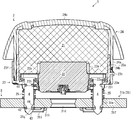
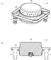
- FIG. 1 is a cross-sectional view showing the overall configuration of the steering wheel according to the first embodiment of the present invention.
- 2 is an enlarged view of a mounting portion of the airbag module shown in FIG.
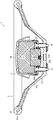
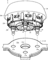
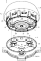
- FIG. 3 is an external view showing a process of attaching the airbag and the inflator to the retainer.
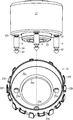
- FIG. 4 is an external view showing a process of attaching the airbag module shown in FIG. 2 to the main body.
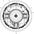
- FIG. 5 is a view showing the back surface of the airbag module.
- the steering wheel 1 includes an airbag 21 that is inflated and deployed in an emergency, an inflator 22 that supplies gas to the airbag 21, an airbag 21, and
- the airbag module 2 includes a retainer 23 that supports the inflator 22, and a main body 3 that is held by an occupant during operation.
- the inflator 22, the retainer 23, and the main body 3 are connected by the same pin 4. Is.
- the airbag module 2 has a module cover 24 that covers the airbag 21, as shown in FIGS.
- the module cover 24 has, for example, a plurality of openings 24b in the side wall portion 24a, and hooks 23b formed on the side surface portion 23a of the retainer 23 are engaged with the openings 24b. Note that a thin portion (tea line) that can be cleaved when the airbag 21 is inflated and deployed is formed on the top 24 c of the module cover 24.
- the airbag 21 has a bag shape having an opening for disposing the inflator 22.
- the folded airbag 21 is shown as one block (block).
- the cross section is shaded with a grid line. It is shown.
- the airbag 21 is configured to be inflated and deployed in a substantially disk shape so that gas is supplied from the inflator 22 to the inside in the event of an emergency such as a vehicle collision, and the body 3 of the steering wheel 1 is covered.
- the inflator 22 has, for example, a substantially cylindrical housing 22a containing a gas generating agent and an ignition device, and a bag ring 22b fitted to the outer periphery of the housing 22a.
- the bag ring 22b may be fixed to the inflator 22 by caulking, or may be fixed by bolts / nuts, rivets or the like.
- a plurality of jet outlets for jetting the generated gas to the outside are formed on the side surface of the housing 22a.
- the bag ring 22b is a bracket-like component configured to project on the outer periphery of the inflator 22.
- the bag ring 22b is formed with fixing holes 22c that can hold the three pins 4 respectively.
- the fixing hole 22c is configured so that the inserted pin 4 can be fixed by caulking.
- the fixing of the pin 4 is not limited to caulking, and the pin 4 may be fixed by screwing into the fixing hole 22c.
- the number and arrangement of the fixing holes 22c are not limited to the illustrated configuration, and are set according to the necessary number and arrangement of the pins 4.
- the retainer 23 is, for example, a container formed by a substantially cylindrical side surface portion 23a having an upper opening as shown in FIG.
- An opening 23d for inserting the inflator 22 is formed at the center of the bottom surface 23c.
- three first insertion holes 23e are formed in the bottom surface portion 23c at positions corresponding to the fixing holes 22c. That is, the first insertion hole 23e is formed in the bottom surface portion 23c so as to be disposed on the concentric axis with respect to the pin 4 fixed to the fixing hole 22c.
- the rear surface portion 23 g of the retainer 23 is loaded with an urging force to the object (specifically, the pin 4) inserted into the first insertion hole 23 e.
- One tension spring 23h is arranged.
- the first tension spring 23h is, for example, arranged so as to be spanned over the first insertion hole 23e, and a substantially linear locking portion 23i that is pushed and urged by an object inserted into the first insertion hole 23e; And a bending portion 23j for applying an elastic force to the locking portion 23i.
- the first tension spring 23h may be formed to have two locking portions 23i and a curved portion 23j by bending both ends of a single steel wire, or a single steel wire. One end of the wire may be bent so as to have one locking portion 23i and one bending portion 23j. Further, as shown in FIG. 5, a plurality of convex portions 23k for positioning the first tension spring 23h and a plurality of guides for horizontally sliding the first tension spring 23h are provided on the back surface portion 23g of the retainer 23. A guide portion 23l is formed.
- a snap-in structure is formed by the first insertion hole 23e and the first tension spring 23h described above.
- the shape and arrangement of the first tension spring 23h, the convex portion 23k, and the guide portion 23l are not limited to the illustrated configuration, and can be arbitrarily changed depending on the position and number of the first insertion holes 23e.
- the first tension spring 23h may be referred to as a first clip.
- the main body 3 includes a cored bar 31 that forms the skeleton of the steering wheel 1 and a resin molded part 32 that covers the cored bar 31 with a resin member.
- the metal core 31 includes an annular rim portion 31a that is held by an occupant during operation, a hub core portion 31b connected to a steering shaft (not shown), a spoke portion 31c that connects the rim portion 31a and the hub core portion 31b, have.
- the resin molding part 32 is formed in a part of the rim part 31a and the spoke part 31c. As illustrated, the airbag module 2 is connected to the hub core portion 31b.
- An opening 31d for connection to a steering shaft (not shown) is formed at the center of the hub core portion 31b.
- the hub core portion 31b is formed with three second insertion holes 31e at positions corresponding to the fixing holes 22c and the first insertion holes 23e. That is, the second insertion hole 31e is formed in the hub core portion 31b so as to be disposed on the concentric shaft with respect to the pin 4 fixed to the fixing hole 22c.
- a second tension is applied to the rear surface portion 31f of the hub core portion 31b so as to apply an urging force to the object (specifically, the pin 4) inserted into the second insertion hole 31e.
- a spring 31g is arranged. Further, a plurality of convex portions 31h for positioning the second tension spring 31g and a plurality of guide portions 31i for guiding the horizontal slide of the second tension spring 31g are formed on the back surface portion 31f of the hub core portion 31b. Has been.
- a snap-in structure is formed by the second insertion hole 31e and the second tension spring 31g described above.
- the shape and arrangement of the second tension spring 31g, the convex portion 31h, and the guide portion 31i are substantially the same as, for example, the first tension spring 23h, the convex portion 23k, and the guide portion 23l shown in FIG. Therefore, detailed drawings and explanation are omitted here.
- the second tension spring 31g may be referred to as a second clip.
- the first recess 41 and the second recess 42 are preferably formed over the entire circumferential direction of the pin 4, for example.
- the first tension spring 23h and the second tension spring 31g are moved to the first when the pin 4 is inserted into the first insertion hole 23e and the second insertion hole 31e.
- the pin 4 can be easily positioned by being locked in the insertion hole 23e and the second insertion hole 31e.
- the pin 4 is pushed in until the first tension spring 23h is locked to the first recess 41.
- the inflator 22 is fixed to the retainer 23 by engaging the first tension spring 23 h with the first recess 41.
- the airbag 21 is fixed to the retainer 23 by sandwiching a part of the airbag 21 between the retainer 23 and the bag ring 22b.
- the coil spring 25 is not shown, it is preferable that the upper end of the coil spring 25 is locked to the back surface 23g of the retainer 23. By holding the coil spring 25 to the retainer 23, the coil spring 25 can be held so as not to drop off during transportation of the airbag module 2 or attachment to the main body 3.
- the main body 3 is manufactured in a separate process from the airbag module 2.
- the cored bar 31 is manufactured, for example, by die-casting such as magnesium or aluminum, or press-molding iron.
- the resin molding part 32 is shape
- the pin 4 is inserted into the second insertion hole 31 e of the main body 3 as shown in FIG.
- the airbag module 2 is connected to the main body 3 by engaging the second tension spring 31g with the second recess 42.
- the coil spring 25 is sandwiched between the airbag module 2 and the main body 3, and the airbag module 2 is urged away from the main body 3 by the coil spring 25.
- the airbag module 2 can be configured to be movable in a direction substantially perpendicular to the hub core portion 31b of the main body 3, and can function as a horn switch.
- the steering wheel 1 according to the first embodiment described above is specifically configured so that the mounting method of the airbag module 2 in which the inflator 22, the retainer 23, and the main body 3 are connected by the same pin 4 can be implemented. It is what.
- the inflator 22, the retainer 23, and the main body 3 are connected by the same pin 4, and therefore the airbag is attached to the retainer 23.
- the portion for fixing 21 and the inflator 22 and the portion for connecting the retainer 23 (airbag module 2) to the main body 3 can be integrated and shared in one place, and the airbag module 2 can be miniaturized. Can do.
- the assembly work can be simplified.
- the assembly work can be easily simplified, and the cost can be effectively reduced.
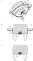
- FIG. 6 is a partially enlarged view of the steering wheel according to the second embodiment of the present invention.
- FIG. 7 is an external view showing a process of attaching the airbag module shown in FIG. 6 to the main body.
- FIG. 8 is an enlarged view showing the inflator shown in FIG. 6, (A) is a perspective view, and (B) is a sectional view.
- FIG. 9 is a view showing a modification of the inflator shown in FIG. 8, where (A) is a perspective view of the first modification, (B) is a cross-sectional view of the first modification, and (C) is a second modification. It is sectional drawing of an example.
- symbol is attached
- the steering wheel 1 is configured such that the airbag module 2 is connected to the horn plate 33 constituting the main body 3.
- the horn plate 33 is connected to the hub core part 31b of the main body part 3 via a coil spring 34, and is configured to be movable in a direction substantially perpendicular to the hub core part 31b.
- the horn plate 33 is formed with a second insertion hole 33a through which the pin 4 is inserted, and a second tension spring 33b is disposed on the back surface to constitute a snap-in structure.
- the coil springs 34 are arranged at three locations so that the horn plate 33 can move in the vertical direction stably. Moreover, since the airbag module 2 in this embodiment should just be fixed to the horn plate 33, it should just have at least 2 pin 4 as shown in the figure. As shown in FIG. 7, the pin 4 is disposed at a position parallel to the left and right, so that the connection of the airbag module 2 to the horn plate 33 can be stabilized.
- the horn plate 33 is configured to interfere with a part of the snap-in structure of the inflator 22 and the retainer 23 (for example, the convex portion 23 k and the guide portion 231).
- an opening or a depression corresponding to the degree of interference may be appropriately formed.
- the number and positions of the first insertion holes and the second insertion holes are changed by changing the number of the pins 4 from three to two.
- the basic configuration of the module 2 is substantially the same as that of the first embodiment. However, the coil spring 25 shown in the first embodiment is not necessary.
- the inflator 22 has a housing 22a and a bag ring 22b.
- the outer periphery of the bag ring 22b has a substantially rectangular shape, but may have a circular shape.
- a space in which a fixing hole 22c for holding the pin 4 can be formed can be formed in the corner portion.
- the fixing hole 22c is formed in the corner portion on the diagonal and the pin 4 is fixed.
- the arrangement of the pins 4 is not limited to the case of being fixed to the bag ring 22b.
- the pins 4 are fixed to the lower surface of the housing 22a. It may be.
- two fixing holes 22c are formed in the lower surface of the housing 22a, and when the inflator 22 is assembled, the pins 4 are inserted into the fixing holes 22c and the fixing holes 22c are caulked to thereby fix the pins 4 to the housing. It fixes to 22a.
- a plurality of hooks 22d for locking a part of the airbag 21 may be formed at the corners of the bag ring 22b.
- the bag ring 22b may be omitted as in the second modification shown in FIG.
- the airbag 21 can be sandwiched between the housing 22a of the inflator 22 and the retainer 23 by inserting a part of the airbag 21 into the pin 4 when the airbag module 2 is manufactured.
- the airbag module 2 can be further reduced in size.
Landscapes
- Engineering & Computer Science (AREA)
- Mechanical Engineering (AREA)
- Chemical & Material Sciences (AREA)
- Combustion & Propulsion (AREA)
- Transportation (AREA)
- Air Bags (AREA)
- Steering Controls (AREA)
Abstract
L'invention concerne un volant de direction et un procédé de montage d'un module de coussin de sécurité gonflable, permettant au module de coussin de sécurité gonflable d'être compact et permettant de simplifier un travail de montage. Un volant de direction comporte : un module 2 de coussin de sécurité gonflable pourvu d'un coussin de sécurité gonflable 21, qui est gonflé et déployé en cas d'urgence, un dispositif de gonflage 22 qui fournit du gaz au coussin de sécurité gonflable 21, et un dispositif de retenue 23 qui supporte le coussin de sécurité gonflable 21 et le dispositif de gonflage 22 ; et une section de corps 3 saisie par un occupant du véhicule pendant le fonctionnement. Le dispositif de gonflage 22, le dispositif de retenue 23, et la section de corps 3 sont reliés par la même broche 4.
Applications Claiming Priority (2)
| Application Number | Priority Date | Filing Date | Title |
|---|---|---|---|
| JP2015-016346 | 2015-01-30 | ||
| JP2015016346A JP6517028B2 (ja) | 2015-01-30 | 2015-01-30 | ステアリングホイール |
Publications (1)
| Publication Number | Publication Date |
|---|---|
| WO2016121274A1 true WO2016121274A1 (fr) | 2016-08-04 |
Family
ID=56542907
Family Applications (1)
| Application Number | Title | Priority Date | Filing Date |
|---|---|---|---|
| PCT/JP2015/085927 WO2016121274A1 (fr) | 2015-01-30 | 2015-12-24 | Volant de direction et procédé de montage de module de coussin de sécurité gonflable |
Country Status (2)
| Country | Link |
|---|---|
| JP (1) | JP6517028B2 (fr) |
| WO (1) | WO2016121274A1 (fr) |
Cited By (2)
| Publication number | Priority date | Publication date | Assignee | Title |
|---|---|---|---|---|
| CN112172908A (zh) * | 2020-09-24 | 2021-01-05 | 盐城同济汽车配件有限公司 | 一种带有减震的方向盘气囊挂钩杆的方向盘骨架 |
| US11285901B2 (en) | 2019-11-18 | 2022-03-29 | Joyson Safety Systems Japan K.K. | Steering wheel |
Families Citing this family (1)
| Publication number | Priority date | Publication date | Assignee | Title |
|---|---|---|---|---|
| KR102638230B1 (ko) * | 2022-01-14 | 2024-02-20 | 아우토리브 디벨롭먼트 아베 | 자동차의 에어백 하우징 |
Citations (6)
| Publication number | Priority date | Publication date | Assignee | Title |
|---|---|---|---|---|
| JPH07205746A (ja) * | 1994-01-04 | 1995-08-08 | General Motors Corp <Gm> | エアバッグモジュール及びその装着、組立て方法 |
| JPH08301052A (ja) * | 1995-05-12 | 1996-11-19 | Toyoda Gosei Co Ltd | エアバッグ装置付きステアリングホイール |
| JPH0930358A (ja) * | 1995-07-21 | 1997-02-04 | Avibank Mfg Inc | エアバッグの取り付けシステム |
| JP3047360U (ja) * | 1996-09-24 | 1998-04-10 | オートリブ エーエスピー,インコーポレイティド | エアバッグインフレータ・モジュール用スナップ式装着付設具、固定子スタッド及びドライバー側搭乗者拘束装置 |
| US6029992A (en) * | 1996-10-02 | 2000-02-29 | General Motors Corporation | Air bag module and steering wheel assembly |
| US6695343B1 (en) * | 2000-11-20 | 2004-02-24 | Trw Vehicle Safety Systems Inc. | Snap-in air bag module |
-
2015
- 2015-01-30 JP JP2015016346A patent/JP6517028B2/ja active Active
- 2015-12-24 WO PCT/JP2015/085927 patent/WO2016121274A1/fr active Application Filing
Patent Citations (6)
| Publication number | Priority date | Publication date | Assignee | Title |
|---|---|---|---|---|
| JPH07205746A (ja) * | 1994-01-04 | 1995-08-08 | General Motors Corp <Gm> | エアバッグモジュール及びその装着、組立て方法 |
| JPH08301052A (ja) * | 1995-05-12 | 1996-11-19 | Toyoda Gosei Co Ltd | エアバッグ装置付きステアリングホイール |
| JPH0930358A (ja) * | 1995-07-21 | 1997-02-04 | Avibank Mfg Inc | エアバッグの取り付けシステム |
| JP3047360U (ja) * | 1996-09-24 | 1998-04-10 | オートリブ エーエスピー,インコーポレイティド | エアバッグインフレータ・モジュール用スナップ式装着付設具、固定子スタッド及びドライバー側搭乗者拘束装置 |
| US6029992A (en) * | 1996-10-02 | 2000-02-29 | General Motors Corporation | Air bag module and steering wheel assembly |
| US6695343B1 (en) * | 2000-11-20 | 2004-02-24 | Trw Vehicle Safety Systems Inc. | Snap-in air bag module |
Cited By (2)
| Publication number | Priority date | Publication date | Assignee | Title |
|---|---|---|---|---|
| US11285901B2 (en) | 2019-11-18 | 2022-03-29 | Joyson Safety Systems Japan K.K. | Steering wheel |
| CN112172908A (zh) * | 2020-09-24 | 2021-01-05 | 盐城同济汽车配件有限公司 | 一种带有减震的方向盘气囊挂钩杆的方向盘骨架 |
Also Published As
| Publication number | Publication date |
|---|---|
| JP2016141176A (ja) | 2016-08-08 |
| JP6517028B2 (ja) | 2019-05-22 |
Similar Documents
| Publication | Publication Date | Title |
|---|---|---|
| JP4923228B2 (ja) | ステアリング・ホイール・ユニット | |
| JP5005019B2 (ja) | ステアリングホイール | |
| JP7094763B2 (ja) | ステアリングホイール | |
| EP2749457B1 (fr) | Structure d'installation d'appareil de coussin de sécurité gonflable de siège de conducteur et roue directrice | |
| WO2016121274A1 (fr) | Volant de direction et procédé de montage de module de coussin de sécurité gonflable | |
| EP2896536B1 (fr) | Structure de montage pour module de coussin gonflable | |
| WO2020162115A1 (fr) | Volant | |
| US20170282835A1 (en) | Steering wheel | |
| JP2014237425A (ja) | ステアリングホイール | |
| JP2011131753A (ja) | パッドカバーの締結構造 | |
| JP2011063167A (ja) | ステアリングホイール | |
| JP6261074B2 (ja) | エアバッグ装置 | |
| JP4985598B2 (ja) | エアバッグ装置付きステアリングホイール | |
| WO2012124633A1 (fr) | Dispositif de coussin de sécurité gonflable et volant | |
| JP6433784B2 (ja) | エアバッグ装置のカバー体 | |
| JP2014196071A (ja) | エアバッグ装置 | |
| JP2011121498A (ja) | ステアリングホイール装置 | |
| JP2017114260A (ja) | 自動車部品 | |
| JP5394145B2 (ja) | エアバッグを備えたステアリング構造 | |
| JP6275489B2 (ja) | ハンドル | |
| WO2010150869A1 (fr) | Structure de dispositif de gonflage de coussin de sécurité gonflable pour véhicule, module de coussin de sécurité gonflable, et structure de coussin de sécurité gonflable | |
| CN113195311A (zh) | 用于机动车辆的转向设备组件 | |
| JP7172698B6 (ja) | エアバッグ装置 | |
| JP2017177930A (ja) | ハンドル | |
| JP2011025916A (ja) | 車両用エアバッグのインフレータ構造、エアバッグモジュールおよびエアバッグ構造 |
Legal Events
| Date | Code | Title | Description |
|---|---|---|---|
| 121 | Ep: the epo has been informed by wipo that ep was designated in this application |
Ref document number: 15880166 Country of ref document: EP Kind code of ref document: A1 |
|
| NENP | Non-entry into the national phase |
Ref country code: DE |
|
| 122 | Ep: pct application non-entry in european phase |
Ref document number: 15880166 Country of ref document: EP Kind code of ref document: A1 |