WO2016121274A1 - ステアリングホイール及びエアバッグモジュールの取付方法 - Google Patents
ステアリングホイール及びエアバッグモジュールの取付方法 Download PDFInfo
- Publication number
- WO2016121274A1 WO2016121274A1 PCT/JP2015/085927 JP2015085927W WO2016121274A1 WO 2016121274 A1 WO2016121274 A1 WO 2016121274A1 JP 2015085927 W JP2015085927 W JP 2015085927W WO 2016121274 A1 WO2016121274 A1 WO 2016121274A1
- Authority
- WO
- WIPO (PCT)
- Prior art keywords
- inflator
- airbag
- retainer
- steering wheel
- main body
- Prior art date
Links
Images

Classifications
-
- B—PERFORMING OPERATIONS; TRANSPORTING
- B60—VEHICLES IN GENERAL
- B60R—VEHICLES, VEHICLE FITTINGS, OR VEHICLE PARTS, NOT OTHERWISE PROVIDED FOR
- B60R21/00—Arrangements or fittings on vehicles for protecting or preventing injuries to occupants or pedestrians in case of accidents or other traffic risks
- B60R21/02—Occupant safety arrangements or fittings, e.g. crash pads
- B60R21/16—Inflatable occupant restraints or confinements designed to inflate upon impact or impending impact, e.g. air bags
- B60R21/20—Arrangements for storing inflatable members in their non-use or deflated condition; Arrangement or mounting of air bag modules or components
- B60R21/203—Arrangements for storing inflatable members in their non-use or deflated condition; Arrangement or mounting of air bag modules or components in steering wheels or steering columns
-
- B—PERFORMING OPERATIONS; TRANSPORTING
- B62—LAND VEHICLES FOR TRAVELLING OTHERWISE THAN ON RAILS
- B62D—MOTOR VEHICLES; TRAILERS
- B62D1/00—Steering controls, i.e. means for initiating a change of direction of the vehicle
- B62D1/02—Steering controls, i.e. means for initiating a change of direction of the vehicle vehicle-mounted
- B62D1/04—Hand wheels
Definitions
- the present invention relates to a method for mounting a steering wheel and an air bag module, and more particularly, to a method for mounting a steering wheel and an air bag module characterized by the structure and method of mounting the air bag module to the steering wheel.
- the airbag and the inflator are fixed to the retainer by bolts and nuts, and the retainer has a fixing pin that connects to the main body.
- the main body described in Patent Document 1 includes a cored bar that forms a skeleton of the steering wheel, and a mounting part that holds the fixing pin is formed on the cored bar.
- the mounting portion includes an insertion hole formed in the metal core and a clip for fixing the fixing pin inserted into the insertion hole, and has a so-called snap-in structure.
- Patent Document 1 As described in Patent Document 1 described above, a mounting method using a snap-in structure has already been adopted between the airbag module and the main body, thereby simplifying the mounting work.
- the operation of attaching the airbag module to the main body is an operation included in the final process, and the airbag module and the main body are individually manufactured at the factory.
- an airbag and an inflator are usually fixed to a retainer with bolts and nuts.
- the conventional air bag module has both a portion for fixing the air bag and the inflator to the retainer and a portion connected to the main body, which limits the size reduction and simplification of the assembling work. was there.
- the present invention was devised in view of such problems, and an object of the present invention is to provide a steering wheel and an attachment method of an airbag module that can reduce the size of the airbag module and simplify the assembly work. To do.
- an airbag module including an airbag that is inflated and deployed in an emergency, an inflator that supplies gas to the airbag, the airbag, and a retainer that supports the inflator, and a passenger grips during operation.
- a steering wheel having a main body portion, wherein the inflator, the retainer, and the main body portion are connected by the same pin is provided.
- a plurality of the pins are fixed to the inflator, and the retainer applies a biasing force to a plurality of first insertion holes formed at positions corresponding to the pins and an object inserted into the first insertion holes.
- a first tension spring arranged in such a manner that the main body portion applies a biasing force to a plurality of second insertion holes formed at positions corresponding to the pins and an object inserted into the second insertion holes.
- a second tension spring disposed so as to load, and the pins are inserted into the first insertion hole and the second insertion hole, respectively, and the pin is moved by the first tension spring and the second tension spring. It may be fixed.
- the pin may include a first recess formed on the base side for locking the first tension spring and a second recess formed on the tip side for locking the second tension spring.
- the pin may be fixed to a housing or a bag ring constituting the inflator.
- the second insertion hole may be formed in a core bar or a horn plate that constitutes the main body.
- an airbag module including an airbag that is inflated and deployed in an emergency, an inflator that supplies gas to the airbag, and a retainer that supports the airbag and the inflator is provided when the steering wheel is operated.
- an air bag module mounting method for connecting an air bag module connected to a main body part gripped by an occupant, wherein the inflator, the retainer and the main body part are connected by the same pin. Is done.
- the pin may be fixed to the inflator, and the pin, the retainer, and the main body may be connected by a snap-in structure.
- the inflator, the retainer and the main body are connected by inserting pins, the assembling work can be simplified.
- the assembling work can be easily simplified, and the cost can be effectively reduced.
- FIG. 8 It is a figure which shows the modification of the inflator shown in FIG. 8, (A) is a perspective view of a 1st modification, (B) is sectional drawing of a 1st modification, (C) is sectional drawing of a 2nd modification. .
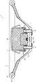
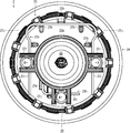
- FIG. 1 is a cross-sectional view showing the overall configuration of the steering wheel according to the first embodiment of the present invention.
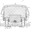
- 2 is an enlarged view of a mounting portion of the airbag module shown in FIG.
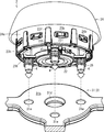
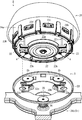
- FIG. 3 is an external view showing a process of attaching the airbag and the inflator to the retainer.
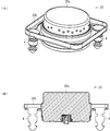
- FIG. 4 is an external view showing a process of attaching the airbag module shown in FIG. 2 to the main body.
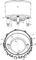
- FIG. 5 is a view showing the back surface of the airbag module.
- the steering wheel 1 includes an airbag 21 that is inflated and deployed in an emergency, an inflator 22 that supplies gas to the airbag 21, an airbag 21, and
- the airbag module 2 includes a retainer 23 that supports the inflator 22, and a main body 3 that is held by an occupant during operation.
- the inflator 22, the retainer 23, and the main body 3 are connected by the same pin 4. Is.
- the airbag module 2 has a module cover 24 that covers the airbag 21, as shown in FIGS.
- the module cover 24 has, for example, a plurality of openings 24b in the side wall portion 24a, and hooks 23b formed on the side surface portion 23a of the retainer 23 are engaged with the openings 24b. Note that a thin portion (tea line) that can be cleaved when the airbag 21 is inflated and deployed is formed on the top 24 c of the module cover 24.
- the airbag 21 has a bag shape having an opening for disposing the inflator 22.
- the folded airbag 21 is shown as one block (block).
- the cross section is shaded with a grid line. It is shown.
- the airbag 21 is configured to be inflated and deployed in a substantially disk shape so that gas is supplied from the inflator 22 to the inside in the event of an emergency such as a vehicle collision, and the body 3 of the steering wheel 1 is covered.
- the inflator 22 has, for example, a substantially cylindrical housing 22a containing a gas generating agent and an ignition device, and a bag ring 22b fitted to the outer periphery of the housing 22a.
- the bag ring 22b may be fixed to the inflator 22 by caulking, or may be fixed by bolts / nuts, rivets or the like.
- a plurality of jet outlets for jetting the generated gas to the outside are formed on the side surface of the housing 22a.
- the bag ring 22b is a bracket-like component configured to project on the outer periphery of the inflator 22.
- the bag ring 22b is formed with fixing holes 22c that can hold the three pins 4 respectively.
- the fixing hole 22c is configured so that the inserted pin 4 can be fixed by caulking.
- the fixing of the pin 4 is not limited to caulking, and the pin 4 may be fixed by screwing into the fixing hole 22c.
- the number and arrangement of the fixing holes 22c are not limited to the illustrated configuration, and are set according to the necessary number and arrangement of the pins 4.
- the retainer 23 is, for example, a container formed by a substantially cylindrical side surface portion 23a having an upper opening as shown in FIG.
- An opening 23d for inserting the inflator 22 is formed at the center of the bottom surface 23c.
- three first insertion holes 23e are formed in the bottom surface portion 23c at positions corresponding to the fixing holes 22c. That is, the first insertion hole 23e is formed in the bottom surface portion 23c so as to be disposed on the concentric axis with respect to the pin 4 fixed to the fixing hole 22c.
- the rear surface portion 23 g of the retainer 23 is loaded with an urging force to the object (specifically, the pin 4) inserted into the first insertion hole 23 e.
- One tension spring 23h is arranged.
- the first tension spring 23h is, for example, arranged so as to be spanned over the first insertion hole 23e, and a substantially linear locking portion 23i that is pushed and urged by an object inserted into the first insertion hole 23e; And a bending portion 23j for applying an elastic force to the locking portion 23i.
- the first tension spring 23h may be formed to have two locking portions 23i and a curved portion 23j by bending both ends of a single steel wire, or a single steel wire. One end of the wire may be bent so as to have one locking portion 23i and one bending portion 23j. Further, as shown in FIG. 5, a plurality of convex portions 23k for positioning the first tension spring 23h and a plurality of guides for horizontally sliding the first tension spring 23h are provided on the back surface portion 23g of the retainer 23. A guide portion 23l is formed.
- a snap-in structure is formed by the first insertion hole 23e and the first tension spring 23h described above.
- the shape and arrangement of the first tension spring 23h, the convex portion 23k, and the guide portion 23l are not limited to the illustrated configuration, and can be arbitrarily changed depending on the position and number of the first insertion holes 23e.
- the first tension spring 23h may be referred to as a first clip.
- the main body 3 includes a cored bar 31 that forms the skeleton of the steering wheel 1 and a resin molded part 32 that covers the cored bar 31 with a resin member.
- the metal core 31 includes an annular rim portion 31a that is held by an occupant during operation, a hub core portion 31b connected to a steering shaft (not shown), a spoke portion 31c that connects the rim portion 31a and the hub core portion 31b, have.
- the resin molding part 32 is formed in a part of the rim part 31a and the spoke part 31c. As illustrated, the airbag module 2 is connected to the hub core portion 31b.
- An opening 31d for connection to a steering shaft (not shown) is formed at the center of the hub core portion 31b.
- the hub core portion 31b is formed with three second insertion holes 31e at positions corresponding to the fixing holes 22c and the first insertion holes 23e. That is, the second insertion hole 31e is formed in the hub core portion 31b so as to be disposed on the concentric shaft with respect to the pin 4 fixed to the fixing hole 22c.
- a second tension is applied to the rear surface portion 31f of the hub core portion 31b so as to apply an urging force to the object (specifically, the pin 4) inserted into the second insertion hole 31e.
- a spring 31g is arranged. Further, a plurality of convex portions 31h for positioning the second tension spring 31g and a plurality of guide portions 31i for guiding the horizontal slide of the second tension spring 31g are formed on the back surface portion 31f of the hub core portion 31b. Has been.
- a snap-in structure is formed by the second insertion hole 31e and the second tension spring 31g described above.
- the shape and arrangement of the second tension spring 31g, the convex portion 31h, and the guide portion 31i are substantially the same as, for example, the first tension spring 23h, the convex portion 23k, and the guide portion 23l shown in FIG. Therefore, detailed drawings and explanation are omitted here.
- the second tension spring 31g may be referred to as a second clip.
- the first recess 41 and the second recess 42 are preferably formed over the entire circumferential direction of the pin 4, for example.
- the first tension spring 23h and the second tension spring 31g are moved to the first when the pin 4 is inserted into the first insertion hole 23e and the second insertion hole 31e.
- the pin 4 can be easily positioned by being locked in the insertion hole 23e and the second insertion hole 31e.
- the pin 4 is pushed in until the first tension spring 23h is locked to the first recess 41.
- the inflator 22 is fixed to the retainer 23 by engaging the first tension spring 23 h with the first recess 41.
- the airbag 21 is fixed to the retainer 23 by sandwiching a part of the airbag 21 between the retainer 23 and the bag ring 22b.
- the coil spring 25 is not shown, it is preferable that the upper end of the coil spring 25 is locked to the back surface 23g of the retainer 23. By holding the coil spring 25 to the retainer 23, the coil spring 25 can be held so as not to drop off during transportation of the airbag module 2 or attachment to the main body 3.
- the main body 3 is manufactured in a separate process from the airbag module 2.
- the cored bar 31 is manufactured, for example, by die-casting such as magnesium or aluminum, or press-molding iron.
- the resin molding part 32 is shape
- the pin 4 is inserted into the second insertion hole 31 e of the main body 3 as shown in FIG.
- the airbag module 2 is connected to the main body 3 by engaging the second tension spring 31g with the second recess 42.
- the coil spring 25 is sandwiched between the airbag module 2 and the main body 3, and the airbag module 2 is urged away from the main body 3 by the coil spring 25.
- the airbag module 2 can be configured to be movable in a direction substantially perpendicular to the hub core portion 31b of the main body 3, and can function as a horn switch.
- the steering wheel 1 according to the first embodiment described above is specifically configured so that the mounting method of the airbag module 2 in which the inflator 22, the retainer 23, and the main body 3 are connected by the same pin 4 can be implemented. It is what.
- the inflator 22, the retainer 23, and the main body 3 are connected by the same pin 4, and therefore the airbag is attached to the retainer 23.
- the portion for fixing 21 and the inflator 22 and the portion for connecting the retainer 23 (airbag module 2) to the main body 3 can be integrated and shared in one place, and the airbag module 2 can be miniaturized. Can do.
- the assembly work can be simplified.
- the assembly work can be easily simplified, and the cost can be effectively reduced.
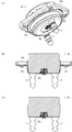
- FIG. 6 is a partially enlarged view of the steering wheel according to the second embodiment of the present invention.
- FIG. 7 is an external view showing a process of attaching the airbag module shown in FIG. 6 to the main body.
- FIG. 8 is an enlarged view showing the inflator shown in FIG. 6, (A) is a perspective view, and (B) is a sectional view.
- FIG. 9 is a view showing a modification of the inflator shown in FIG. 8, where (A) is a perspective view of the first modification, (B) is a cross-sectional view of the first modification, and (C) is a second modification. It is sectional drawing of an example.
- symbol is attached
- the steering wheel 1 is configured such that the airbag module 2 is connected to the horn plate 33 constituting the main body 3.
- the horn plate 33 is connected to the hub core part 31b of the main body part 3 via a coil spring 34, and is configured to be movable in a direction substantially perpendicular to the hub core part 31b.
- the horn plate 33 is formed with a second insertion hole 33a through which the pin 4 is inserted, and a second tension spring 33b is disposed on the back surface to constitute a snap-in structure.
- the coil springs 34 are arranged at three locations so that the horn plate 33 can move in the vertical direction stably. Moreover, since the airbag module 2 in this embodiment should just be fixed to the horn plate 33, it should just have at least 2 pin 4 as shown in the figure. As shown in FIG. 7, the pin 4 is disposed at a position parallel to the left and right, so that the connection of the airbag module 2 to the horn plate 33 can be stabilized.
- the horn plate 33 is configured to interfere with a part of the snap-in structure of the inflator 22 and the retainer 23 (for example, the convex portion 23 k and the guide portion 231).
- an opening or a depression corresponding to the degree of interference may be appropriately formed.
- the number and positions of the first insertion holes and the second insertion holes are changed by changing the number of the pins 4 from three to two.
- the basic configuration of the module 2 is substantially the same as that of the first embodiment. However, the coil spring 25 shown in the first embodiment is not necessary.
- the inflator 22 has a housing 22a and a bag ring 22b.
- the outer periphery of the bag ring 22b has a substantially rectangular shape, but may have a circular shape.
- a space in which a fixing hole 22c for holding the pin 4 can be formed can be formed in the corner portion.
- the fixing hole 22c is formed in the corner portion on the diagonal and the pin 4 is fixed.
- the arrangement of the pins 4 is not limited to the case of being fixed to the bag ring 22b.
- the pins 4 are fixed to the lower surface of the housing 22a. It may be.
- two fixing holes 22c are formed in the lower surface of the housing 22a, and when the inflator 22 is assembled, the pins 4 are inserted into the fixing holes 22c and the fixing holes 22c are caulked to thereby fix the pins 4 to the housing. It fixes to 22a.
- a plurality of hooks 22d for locking a part of the airbag 21 may be formed at the corners of the bag ring 22b.
- the bag ring 22b may be omitted as in the second modification shown in FIG.
- the airbag 21 can be sandwiched between the housing 22a of the inflator 22 and the retainer 23 by inserting a part of the airbag 21 into the pin 4 when the airbag module 2 is manufactured.
- the airbag module 2 can be further reduced in size.
Abstract
エアバッグモジュールの小型化及び組付作業の簡略化を図ることができる、ステアリングホイール及びエアバッグモジュールの取付方法を提供する。 緊急時に膨張展開されるエアバッグ21とエアバッグ21にガスを供給するインフレータ22とエアバッグ21及びインフレータ22を支持するリテーナ23とを備えたエアバッグモジュール2と、操作時に乗員が把持する本体部3と、を有し、インフレータ22、リテーナ23及び本体部3が同一のピン4で接続されている。
Description
本発明は、ステアリングホイール及びエアバッグモジュールの取付方法に関し、特に、ステアリングホイールへのエアバッグモジュールの取付構造及び方法に特徴を有するステアリングホイール及びエアバッグモジュールの取付方法に関する。
自動車等の乗物の舵角を操作するステアリングホイールは、一般に、緊急時に膨張展開されるエアバッグと該エアバッグにガスを供給するインフレータと前記エアバッグ及び前記インフレータを支持するリテーナとを備えたエアバッグモジュールと、操作時に乗員が把持する本体部と、を有している(例えば、特許文献1参照)。
特許文献1に記載されたエアバッグモジュールは、エアバッグ及びインフレータがリテーナにボルト・ナットにより固定されており、リテーナに本体部に接続する固定ピンを有している。また、特許文献1に記載された本体部は、ステアリングホイールの骨格を形成する芯金を有し、該芯金に前記固定ピンを保持する装着部が形成されている。この装着部は、芯金に形成された挿入孔と、該挿入孔に挿入された前記固定ピンを固定するクリップと、を備え、いわゆるスナップイン構造を有している。
上述した特許文献1に記載されたように、エアバッグモジュールと本体部との間では、既にスナップイン構造による取付方法が採用されており、取付作業の簡略化が図られている。一般に、ステアリングホイールの製造工程において、本体部へのエアバッグモジュールの取付作業は最終工程に含まれる作業であり、エアバッグモジュールと本体部とはそれぞれ個別に工場で製造される。そして、特許文献1に記載されたように、エアバッグモジュールは、通常、エアバッグ及びインフレータがリテーナにボルト・ナットにより固定されている。
近年、ステアリングホイールの高機能化やコストダウン等の観点から、エアバッグモジュールのより一層の小型化やコストダウンが求められている。しかしながら、従来のエアバッグモジュールでは、リテーナにエアバッグ及びインフレータを固定する部分と本体部に接続する部分との両方を有しており、エアバッグモジュールの小型化や組付作業の簡略化に限界があった。
本発明はかかる問題点に鑑み創案されたものであり、エアバッグモジュールの小型化及び組付作業の簡略化を図ることができる、ステアリングホイール及びエアバッグモジュールの取付方法を提供することを目的とする。
本発明によれば、緊急時に膨張展開されるエアバッグと該エアバッグにガスを供給するインフレータと前記エアバッグ及び前記インフレータを支持するリテーナとを備えたエアバッグモジュールと、操作時に乗員が把持する本体部と、を有するステアリングホイールにおいて、前記インフレータ、前記リテーナ及び前記本体部が同一のピンで接続されている、ことを特徴とするステアリングホイールが提供される。
前記ピンは、前記インフレータに複数固定されており、前記リテーナは、前記ピンと対応する位置に形成された複数の第一挿通孔と、該第一挿通孔に挿入された物体に付勢力を負荷するように配置された第一テンションスプリングと、を備え、前記本体部は、前記ピンと対応する位置に形成された複数の第二挿通孔と、該第二挿通孔に挿入された物体に付勢力を負荷するように配置された第二テンションスプリングと、を備え、前記ピンをそれぞれ前記第一挿通孔及び前記第二挿通孔に挿入し、前記第一テンションスプリング及び前記第二テンションスプリングにより前記ピンを固定するようにしてもよい。
前記ピンは、根元側に形成され前記第一テンションスプリングを係止する第一凹部と、先端側に形成され前記第二テンションスプリングを係止する第二凹部と、を備えていてもよい。
前記ピンは、前記インフレータを構成するハウジング又はバッグリングに固定されていてもよい。また、前記第二挿通孔は、前記本体部を構成する芯金又はホーンプレートに形成されていてもよい。
また、本発明によれば、緊急時に膨張展開されるエアバッグと該エアバッグにガスを供給するインフレータと前記エアバッグ及び前記インフレータを支持するリテーナとを備えたエアバッグモジュールをステアリングホイールの操作時に乗員が把持する本体部に接続するエアバッグモジュールの取付方法において、前記インフレータ、前記リテーナ及び前記本体部を同一のピンで接続するようにした、ことを特徴とするエアバッグモジュールの取付方法が提供される。
前記ピンを前記インフレータに固定し、前記ピンと前記リテーナ及び前記本体部とをスナップイン構造によって接続するようにしてもよい。
上述した本発明に係るステアリングホイール及びエアバッグモジュールの取付方法によれば、インフレータ、リテーナ及び本体部を同一のピンで接続するようにしたことから、リテーナにエアバッグ及びインフレータを固定する部分とリテーナ(エアバッグモジュール)を本体部に接続する部分とを一箇所に集約して共有化することができ、エアバッグモジュールの小型化を図ることができる。
また、インフレータ、リテーナ及び本体部にピンを差し込んで接続するようにしたことから、組付作業の簡略化を図ることもできる。特に、ピンとリテーナ及び本体部との接続にスナップイン構造を採用することにより、組付作業の簡略化を容易に図ることができ、効果的にコストダウンすることができる。
以下、本発明の実施形態について図1~図9(C)を用いて説明する。ここで、図1は、本発明の第一実施形態に係るステアリングホイールの全体構成を示す断面図である。図2は、図1に示したエアバッグモジュールの取付部の拡大図である。図3は、エアバッグ及びインフレータのリテーナへの取付工程を示す外観図である。図4は、図2に示したエアバッグモジュールの本体部への取付工程を示す外観図である。図5は、エアバッグモジュールの裏面を示す図である。
本発明の第一実施形態に係るステアリングホイール1は、図1及び図2に示したように、緊急時に膨張展開されるエアバッグ21とエアバッグ21にガスを供給するインフレータ22とエアバッグ21及びインフレータ22を支持するリテーナ23とを備えたエアバッグモジュール2と、操作時に乗員が把持する本体部3と、を有し、インフレータ22、リテーナ23及び本体部3が同一のピン4で接続されたものである。
エアバッグモジュール2は、図2及び図4に示したように、エアバッグ21を覆うモジュールカバー24を有している。かかるモジュールカバー24は、例えば、側壁部24aに複数の開口部24bを有しており、この開口部24bにはリテーナ23の側面部23aに形成されたフック23bが係止される。なお、モジュールカバー24の頂部24cには、エアバッグ21の膨張展開時に開裂可能な薄肉部(テアライン)が形成されている。
エアバッグ21は、インフレータ22を配置するための開口部を有する袋状を有している。図1~図3の各図において、説明の便宜上、エアバッグ21を折り畳んだ状態を一つのブロック(塊)として図示し、図1及び図2では、その断面に格子線の網掛を付して図示している。エアバッグ21は、車両衝突時等の緊急時にインフレータ22から内部にガスが供給され、ステアリングホイール1の本体部3を覆うように、略円盤状に膨張展開するように構成されている。
インフレータ22は、例えば、ガス発生剤や点火装置を内蔵する略円筒形状のハウジング22aと、ハウジング22aの外周に嵌合されたバッグリング22bと、を有している。なお、バッグリング22bは、インフレータ22にカシメにより固定されていてもよいし、ボルト・ナットやリベット等により固定されていてもよい。また、ハウジング22aの側面部には、発生したガスを外部に噴き出す複数の噴出口が形成されている。
バッグリング22bは、インフレータ22の外周に張り出されるように構成されたブラケット状の部品である。このバッグリング22bには、例えば、図3に示したように、三本のピン4をそれぞれ保持可能な固定孔22cが形成されている。固定孔22cは、挿入されたピン4をカシメによって固定できるように構成されている。なお、ピン4の固定は、カシメに限定されるものではなく、ピン4を固定孔22cに螺合して固定するようにしてもよい。また、固定孔22cの個数及び配置は、図示した構成に限定されるものではなく、必要なピン4の本数及び配置に応じて設定される。
リテーナ23は、例えば、図3に示したように、上部が開口した略円筒形状の側面部23aにより形成された容器である。底面部23cの中央部には、インフレータ22を挿入するための開口部23dが形成されている。また、底面部23cには、固定孔22cと対応する位置に三個の第一挿通孔23eが形成されている。すなわち、第一挿通孔23eは、固定孔22cに固定されたピン4に対して、同心軸上に配置されるように底面部23cに形成されている。
また、リテーナ23の側面部23aには、モジュールカバー24を挿通するスリットを形成するための複数の突起23fが形成されている。なお、リテーナ23の構成は図示したものに限定されず、例えば、フック23bや突起23fの個数や配置は、ステアリングホイール1の種類等に応じて任意に設定される。また、リテーナ23の外形も円筒形状に限定されるものではなく、エアバッグ21の折り畳み形状や本体部3の形状等に応じて任意に変更することができる。
また、リテーナ23の裏面部23gには、図4及び図5に示したように、第一挿通孔23eに挿入された物体(具体的には、ピン4)に付勢力を負荷するように第一テンションスプリング23hが配置されている。第一テンションスプリング23hは、例えば、第一挿通孔23eに掛け渡されるように配置され、第一挿通孔23eに挿入された物体により押し退けられて付勢する略直線状の係止部23iと、この係止部23iに弾性力を付与する湾曲部23jと、を有している。
図5に示したように、第一テンションスプリング23hは、一本のスチールワイヤの両端を折り曲げて二つの係止部23i及び湾曲部23jを有するように形成してもよいし、一本のスチールワイヤの一端を折り曲げて一つの係止部23i及び湾曲部23jを有するように形成してもよい。また、リテーナ23の裏面部23gには、図5に示したように、第一テンションスプリング23hの位置決めをする複数の凸部23kと、第一テンションスプリング23hの水平方向のスライドを案内する複数のガイド部23lと、が形成されている。
上述した第一挿通孔23e及び第一テンションスプリング23hにより、スナップイン構造が形成される。なお、第一テンションスプリング23h、凸部23k及びガイド部23lの形状や配置は図示した構成に限定されるものではなく、第一挿通孔23eの位置や個数等によって任意に変更することができる。また、第一テンションスプリング23hは、第一クリップと称してもよい。
本体部3は、図1に示したように、ステアリングホイール1の骨格を形成する芯金31と、芯金31を樹脂部材により被覆した樹脂成形部32と、を有している。芯金31は、操作時に乗員が把持する環状のリム部31aと、ステアリングシャフト(図示せず)に接続されるハブコア部31bと、リム部31aとハブコア部31bとを連結するスポーク部31cと、を有している。樹脂成形部32は、リム部31a及びスポーク部31cの一部に形成される。図示したように、エアバッグモジュール2は、ハブコア部31bに接続される。
ハブコア部31bの中央部には、ステアリングシャフト(図示せず)に接続するための開口部31dが形成されている。また、ハブコア部31bには、固定孔22c及び第一挿通孔23eと対応する位置に三個の第二挿通孔31eが形成されている。すなわち、第二挿通孔31eは、固定孔22cに固定されたピン4に対して、同心軸上に配置されるようにハブコア部31bに形成されている。
また、ハブコア部31bの裏面部31fには、図2に示したように、第二挿通孔31eに挿入された物体(具体的には、ピン4)に付勢力を負荷するように第二テンションスプリング31gが配置されている。また、ハブコア部31bの裏面部31fには、第二テンションスプリング31gの位置決めをする複数の凸部31hと、第二テンションスプリング31gの水平方向のスライドを案内する複数のガイド部31iと、が形成されている。
上述した第二挿通孔31e及び第二テンションスプリング31gにより、スナップイン構造が形成される。なお、第二テンションスプリング31g、凸部31h及びガイド部31iの形状や配置は、例えば、図5に示した、第一テンションスプリング23h、凸部23k及びガイド部23lと実質的に同一であることから、ここでは詳細な図と説明を省略する。また、第二テンションスプリング31gは、第二クリップと称してもよい。
なお、上述した第一実施形態に係るステアリングホイール1において、図示しないが、リテーナ23の裏面部23gに可動接点が配置され、ハブコア部31bの表面部に固定接点が配置され、この可動接点及び固定接点によりホーンスイッチが構成される。
ピン4は、例えば、固定孔22c、第一挿通孔23e及び第二挿通孔31eに挿入される軸部と、一端に拡径するように形成された頭部と、を有している。ピン4の軸部は、エアバッグモジュール2を本体部3に接続する部品であることから、所定の強度を有している。また、ピン4は、根元側に形成され第一テンションスプリング23hを係止する第一凹部41と、先端側に形成され第二テンションスプリング31gを係止する第二凹部42と、を備えている。
第一凹部41及び第二凹部42は、例えば、ピン4の周方向の全域に渡って形成することが好ましい。かかる第一凹部41及び第二凹部42を形成することにより、ピン4を第一挿通孔23e及び第二挿通孔31eに挿入した際に、第一テンションスプリング23h及び第二テンションスプリング31gを第一挿通孔23e及び第二挿通孔31eに係止させることができ、ピン4の位置決めを容易に行うことができる。
また、ピン4の先端部43に形成された傾斜と、第二凹部42の根元側に形成されたテーパ部44の傾斜とは、略平行に形成されていてもよい。かかるテーパ部44を形成することにより、ピン4をリテーナ23の第一挿通孔23eに挿入した際に、第一テンションスプリング23hが第二凹部42に嵌まった場合でも、ピン4を押し込むことにより、第一テンションスプリング23hを第二凹部42から容易に離脱させることができる。
図2に示したように、ピン4は、バッグリング22bの固定孔22cに挿通され、頭部をバッグリング22bの表面に接触させた状態で固定孔22cをカシメることにより、バッグリング22bに固定される。次に、ピン4は、エアバッグ21のインフレータ22用の開口部の周囲に形成された孔やスリットに挿入された後、図3に示したように、リテーナ23の第一挿通孔23eに挿入される。
ピン4は、第一テンションスプリング23hが第一凹部41に係止されるまで押し込まれる。第一テンションスプリング23hを第一凹部41に係止させることにより、インフレータ22がリテーナ23に固定される。このとき、エアバッグ21の一部をリテーナ23とバッグリング22bとの間に挟持させることにより、エアバッグ21がリテーナ23に固定される。
その後、リテーナ23にモジュールカバー24を被せて、リテーナ23のフック23bをモジュールカバー24の開口部24bに係止させることにより、エアバッグモジュール2を組み付ける。最後に、図4に示したように、エアバッグモジュール2を本体部3から離反するように付勢するコイルスプリング25をピン4の外周に挿通する。
コイルスプリング25は、図示しないが、上端部をリテーナ23の裏面部23gに係止させておくことが好ましい。コイルスプリング25をリテーナ23に係止させておくことにより、エアバッグモジュール2の運搬時や本体部3への取付作業時にコイルスプリング25が脱落しないように保持することができる。
一方、本体部3は、エアバッグモジュール2とは別工程で製造される。芯金31は、例えば、マグネシウムやアルミニウム等のダイキャスト成型や鉄のプレス成型等により製造される。また、樹脂成形部32は、例えば、モールド成形等により成形される。
そして、エアバッグモジュール2を本体部3に組み付ける際には、図4に示したように、ピン4を本体部3の第二挿通孔31eに挿入する。このとき、第二テンションスプリング31gを第二凹部42に係止させることにより、エアバッグモジュール2が本体部3に接続される。コイルスプリング25は、エアバッグモジュール2と本体部3との間に挟持され、エアバッグモジュール2は、コイルスプリング25により本体部3から離反するように付勢される。かかる構成により、エアバッグモジュール2を本体部3のハブコア部31bに対して略垂直な方向に移動可能に構成することができ、ホーンスイッチとして機能させることができる。
上述した第一実施形態に係るステアリングホイール1は、ピン4がインフレータ22を構成するバッグリング22bに三本固定されており、リテーナ23は、ピン4と対応する位置に形成された三個の第一挿通孔23eと、第一挿通孔23eに挿入された物体に付勢力を負荷するように配置された第一テンションスプリング23hと、を備え、本体部3は、ピン4と対応する位置に形成された三個の第二挿通孔31eと、第二挿通孔31eに挿入された物体に付勢力を負荷するように配置された第二テンションスプリング31gと、を備え、ピン4をそれぞれ第一挿通孔23e及び第二挿通孔31eに挿入し、第一テンションスプリング23h及び第二テンションスプリング31gによりピン4を固定するようにしたものである。
すなわち、上述した第一実施形態に係るステアリングホイール1は、インフレータ22、リテーナ23及び本体部3を同一のピン4で接続するようにしたエアバッグモジュール2の取付方法を具現可能に具体的に構成したものである。
上述した本実施形態に係るステアリングホイール1及びエアバッグモジュール2の取付方法によれば、インフレータ22、リテーナ23及び本体部3を同一のピン4で接続するようにしたことから、リテーナ23にエアバッグ21及びインフレータ22を固定する部分とリテーナ23(エアバッグモジュール2)を本体部3に接続する部分とを一箇所に集約して共有化することができ、エアバッグモジュール2の小型化を図ることができる。
また、インフレータ22、リテーナ23及び本体部3にピン4を差し込んで接続するようにしたことから、組付作業の簡略化を図ることもできる。特に、ピン4とリテーナ23及び本体部3との接続にスナップイン構造を採用することにより、組付作業の簡略化を容易に図ることができ、効果的にコストダウンすることができる。
次に、本発明の第二実施形態に係るステアリングホイール1について、図6~図9(C)を参照しつつ説明する。ここで、図6は、本発明の第二実施形態に係るステアリングホイールの部分拡大図である。図7は、図6に示したエアバッグモジュールの本体部への取付工程を示す外観図である。図8は、図6に示したインフレータを示す拡大図であり、(A)は斜視図、(B)は断面図、である。図9は、図8に示したインフレータの変形例を示す図であり、(A)は第一変形例の斜視図、(B)は第一変形例の断面図、(C)は第二変形例の断面図、である。なお、上述した第一実施形態に係るステアリングホイール1と同一の構成部品については、同一の符号を付して重複した説明を省略する。
第二実施形態に係るステアリングホイール1は、図6及び図7に示したように、本体部3を構成するホーンプレート33にエアバッグモジュール2を接続するようにしたものである。ホーンプレート33は、本体部3のハブコア部31bにコイルスプリング34を介して接続されており、ハブコア部31bに対して略垂直な方向に移動可能に構成されている。また、ホーンプレート33には、ピン4を挿通する第二挿通孔33aが形成されるとともに、裏面に第二テンションスプリング33bが配置され、スナップイン構造が構成されている。
具体的には、ハブコア部31bに三本のショルダーナット35が立設されており、ショルダーナット35の軸部にコイルスプリング34が挿通されており、ホーンプレート33は、コイルスプリング34によりショルダーナット35の頭部に押し付けられるように付勢されている。なお、図示しないが、ホーンプレート33の裏面部に可動接点が配置され、ハブコア部31bの表面部に固定接点が配置され、この可動接点及び固定接点によりホーンスイッチが構成される。
本実施形態では、ホーンプレート33が安定して上下方向に移動することができるように、三箇所にコイルスプリング34を配置している。また、本実施形態におけるエアバッグモジュール2は、ホーンプレート33に固定することができればよいことから、図示したように、少なくとも二本のピン4を有していればよい。このピン4は、図7に示したように、左右に並列する位置に配置することにより、エアバッグモジュール2のホーンプレート33への接続を安定させることができる。
なお、エアバッグモジュール2をホーンプレート33に接続した際に、インフレータ22及びリテーナ23のスナップイン構造の一部(例えば、凸部23kやガイド部23l等)と干渉する部分については、ホーンプレート33に干渉の程度に応じた開口部や窪みを適宜形成するようにしてもよい。
第二実施形態に係るステアリングホイール1では、ピン4の本数を三本から二本に変更したことにより、第一挿通孔や第二挿通孔の個数や位置も変更することになるが、エアバッグモジュール2の基本的な構成は第一実施形態と実質的に同一である。ただし、第一実施形態に示したコイルスプリング25は不要である。
本実施形態に係るステアリングホイール1においても、図8(A)及び(B)に示したように、インフレータ22は、ハウジング22aとバッグリング22bとを有している。ここで、バッグリング22bは、外周が略矩形形状を有しているが、円形状であってもよい。かかるバッグリング22bでは、角隅部にピン4を保持する固定孔22cを形成可能な空間を形成することができ、例えば、対角線上の角隅部に固定孔22cが形成されピン4が固定される。
ピン4の配置は、バッグリング22bに固定される場合に限定されるものではなく、例えば、図9(A)及び(B)に示したように、ハウジング22aの下面にピン4を固定するようにしてもよい。かかる第一変形例では、ハウジング22aの下面に二個の固定孔22cを形成し、インフレータ22の組立時にピン4を固定孔22cに挿通して固定孔22cをカシメることにより、ピン4をハウジング22aに固定する。このとき、バッグリング22bの角隅部には、エアバッグ21の一部を係止する複数のフック22dを形成しておいてもよい。
このように、インフレータ22を構成するハウジング22aの下面にピン4を固定することにより、バッグリング22bにピン4を固定するための空間を形成する必要がなく、バッグリング22bの小型化を図ることができ、インフレータ22及びエアバッグモジュール2の小型化を図ることができる。
さらに、図9(C)に示した第二変形例のように、バッグリング22bを省略するようにしてもよい。この場合、エアバッグモジュール2の製作時にエアバッグ21の一部をピン4に挿通することにより、インフレータ22のハウジング22aとリテーナ23との間でエアバッグ21を挟持することができる。かかる第二変形例によれば、エアバッグモジュール2の更なる小型化を図ることができる。
本発明は上述した実施形態に限定されず、本発明の趣旨を逸脱しない範囲で種々変更が可能であることは勿論である。
Claims (7)
- 緊急時に膨張展開されるエアバッグと該エアバッグにガスを供給するインフレータと前記エアバッグ及び前記インフレータを支持するリテーナとを備えたエアバッグモジュールと、操作時に乗員が把持する本体部と、を有するステアリングホイールにおいて、
前記インフレータ、前記リテーナ及び前記本体部が同一のピンで接続されている、
ことを特徴とするステアリングホイール。 - 前記ピンは、前記インフレータに複数固定されており、
前記リテーナは、前記ピンと対応する位置に形成された複数の第一挿通孔と、該第一挿通孔に挿入された物体に付勢力を負荷するように配置された第一テンションスプリングと、を備え、
前記本体部は、前記ピンと対応する位置に形成された複数の第二挿通孔と、該第二挿通孔に挿入された物体に付勢力を負荷するように配置された第二テンションスプリングと、を備え、
前記ピンをそれぞれ前記第一挿通孔及び前記第二挿通孔に挿入し、前記第一テンションスプリング及び前記第二テンションスプリングにより前記ピンを固定するようにした、
ことを特徴とする請求項1に記載のステアリングホイール。 - 前記ピンは、根元側に形成され前記第一テンションスプリングを係止する第一凹部と、先端側に形成され前記第二テンションスプリングを係止する第二凹部と、を備えていることを特徴とする請求項2に記載のステアリングホイール。
- 前記ピンは、前記インフレータを構成するハウジング又はバッグリングに固定されている、ことを特徴とする請求項2に記載のステアリングホイール。
- 前記第二挿通孔は、前記本体部を構成する芯金又はホーンプレートに形成されている、ことを特徴とする請求項2に記載のステアリングホイール。
- 緊急時に膨張展開されるエアバッグと該エアバッグにガスを供給するインフレータと前記エアバッグ及び前記インフレータを支持するリテーナとを備えたエアバッグモジュールをステアリングホイールの操作時に乗員が把持する本体部に接続するエアバッグモジュールの取付方法において、
前記インフレータ、前記リテーナ及び前記本体部を同一のピンで接続するようにした、ことを特徴とするエアバッグモジュールの取付方法。 - 前記ピンを前記インフレータに固定し、前記ピンと前記リテーナ及び前記本体部とをスナップイン構造によって接続するようにした、ことを特徴とする請求項6に記載のエアバッグモジュールの取付方法。
Applications Claiming Priority (2)
| Application Number | Priority Date | Filing Date | Title |
|---|---|---|---|
| JP2015-016346 | 2015-01-30 | ||
| JP2015016346A JP6517028B2 (ja) | 2015-01-30 | 2015-01-30 | ステアリングホイール |
Publications (1)
| Publication Number | Publication Date |
|---|---|
| WO2016121274A1 true WO2016121274A1 (ja) | 2016-08-04 |
Family
ID=56542907
Family Applications (1)
| Application Number | Title | Priority Date | Filing Date |
|---|---|---|---|
| PCT/JP2015/085927 WO2016121274A1 (ja) | 2015-01-30 | 2015-12-24 | ステアリングホイール及びエアバッグモジュールの取付方法 |
Country Status (2)
| Country | Link |
|---|---|
| JP (1) | JP6517028B2 (ja) |
| WO (1) | WO2016121274A1 (ja) |
Cited By (1)
| Publication number | Priority date | Publication date | Assignee | Title |
|---|---|---|---|---|
| US11285901B2 (en) | 2019-11-18 | 2022-03-29 | Joyson Safety Systems Japan K.K. | Steering wheel |
Families Citing this family (1)
| Publication number | Priority date | Publication date | Assignee | Title |
|---|---|---|---|---|
| KR102638230B1 (ko) * | 2022-01-14 | 2024-02-20 | 아우토리브 디벨롭먼트 아베 | 자동차의 에어백 하우징 |
Citations (6)
| Publication number | Priority date | Publication date | Assignee | Title |
|---|---|---|---|---|
| JPH07205746A (ja) * | 1994-01-04 | 1995-08-08 | General Motors Corp <Gm> | エアバッグモジュール及びその装着、組立て方法 |
| JPH08301052A (ja) * | 1995-05-12 | 1996-11-19 | Toyoda Gosei Co Ltd | エアバッグ装置付きステアリングホイール |
| JPH0930358A (ja) * | 1995-07-21 | 1997-02-04 | Avibank Mfg Inc | エアバッグの取り付けシステム |
| JP3047360U (ja) * | 1996-09-24 | 1998-04-10 | オートリブ エーエスピー,インコーポレイティド | エアバッグインフレータ・モジュール用スナップ式装着付設具、固定子スタッド及びドライバー側搭乗者拘束装置 |
| US6029992A (en) * | 1996-10-02 | 2000-02-29 | General Motors Corporation | Air bag module and steering wheel assembly |
| US6695343B1 (en) * | 2000-11-20 | 2004-02-24 | Trw Vehicle Safety Systems Inc. | Snap-in air bag module |
-
2015
- 2015-01-30 JP JP2015016346A patent/JP6517028B2/ja active Active
- 2015-12-24 WO PCT/JP2015/085927 patent/WO2016121274A1/ja active Application Filing
Patent Citations (6)
| Publication number | Priority date | Publication date | Assignee | Title |
|---|---|---|---|---|
| JPH07205746A (ja) * | 1994-01-04 | 1995-08-08 | General Motors Corp <Gm> | エアバッグモジュール及びその装着、組立て方法 |
| JPH08301052A (ja) * | 1995-05-12 | 1996-11-19 | Toyoda Gosei Co Ltd | エアバッグ装置付きステアリングホイール |
| JPH0930358A (ja) * | 1995-07-21 | 1997-02-04 | Avibank Mfg Inc | エアバッグの取り付けシステム |
| JP3047360U (ja) * | 1996-09-24 | 1998-04-10 | オートリブ エーエスピー,インコーポレイティド | エアバッグインフレータ・モジュール用スナップ式装着付設具、固定子スタッド及びドライバー側搭乗者拘束装置 |
| US6029992A (en) * | 1996-10-02 | 2000-02-29 | General Motors Corporation | Air bag module and steering wheel assembly |
| US6695343B1 (en) * | 2000-11-20 | 2004-02-24 | Trw Vehicle Safety Systems Inc. | Snap-in air bag module |
Cited By (1)
| Publication number | Priority date | Publication date | Assignee | Title |
|---|---|---|---|---|
| US11285901B2 (en) | 2019-11-18 | 2022-03-29 | Joyson Safety Systems Japan K.K. | Steering wheel |
Also Published As
| Publication number | Publication date |
|---|---|
| JP2016141176A (ja) | 2016-08-08 |
| JP6517028B2 (ja) | 2019-05-22 |
Similar Documents
| Publication | Publication Date | Title |
|---|---|---|
| JP4923228B2 (ja) | ステアリング・ホイール・ユニット | |
| JP5005019B2 (ja) | ステアリングホイール | |
| JP7094763B2 (ja) | ステアリングホイール | |
| EP2749457B1 (en) | Driver seat air bag apparatus installation structure and steering wheel | |
| EP2896536B1 (en) | Mounting structure for airbag module | |
| WO2020162115A1 (ja) | ステアリングホイール | |
| US20170282835A1 (en) | Steering wheel | |
| JP2014237425A (ja) | ステアリングホイール | |
| WO2016121274A1 (ja) | ステアリングホイール及びエアバッグモジュールの取付方法 | |
| JP2011131753A (ja) | パッドカバーの締結構造 | |
| JP2010201979A (ja) | エアバッグ装置 | |
| JP6261074B2 (ja) | エアバッグ装置 | |
| JP4985598B2 (ja) | エアバッグ装置付きステアリングホイール | |
| WO2012124633A1 (ja) | エアバッグ装置及びステアリングホイール | |
| JP6433784B2 (ja) | エアバッグ装置のカバー体 | |
| JP2014196071A (ja) | エアバッグ装置 | |
| JP2011121498A (ja) | ステアリングホイール装置 | |
| JP2017114260A (ja) | 自動車部品 | |
| JP5394145B2 (ja) | エアバッグを備えたステアリング構造 | |
| JP6275489B2 (ja) | ハンドル | |
| WO2010150869A1 (ja) | 車両用エアバッグのインフレータ構造、エアバッグモジュールおよびエアバッグ構造 | |
| JP7172698B2 (ja) | エアバッグ装置 | |
| JP2017177930A (ja) | ハンドル | |
| JP6253196B2 (ja) | ハンドル | |
| JP2011025916A (ja) | 車両用エアバッグのインフレータ構造、エアバッグモジュールおよびエアバッグ構造 |
Legal Events
| Date | Code | Title | Description |
|---|---|---|---|
| 121 | Ep: the epo has been informed by wipo that ep was designated in this application |
Ref document number: 15880166 Country of ref document: EP Kind code of ref document: A1 |
|
| NENP | Non-entry into the national phase |
Ref country code: DE |
|
| 122 | Ep: pct application non-entry in european phase |
Ref document number: 15880166 Country of ref document: EP Kind code of ref document: A1 |