WO2016120917A1 - 非水電解質二次電池の放電制御装置及び方法 - Google Patents
非水電解質二次電池の放電制御装置及び方法 Download PDFInfo
- Publication number
- WO2016120917A1 WO2016120917A1 PCT/JP2015/004516 JP2015004516W WO2016120917A1 WO 2016120917 A1 WO2016120917 A1 WO 2016120917A1 JP 2015004516 W JP2015004516 W JP 2015004516W WO 2016120917 A1 WO2016120917 A1 WO 2016120917A1
- Authority
- WO
- WIPO (PCT)
- Prior art keywords
- secondary battery
- discharge
- electrolyte secondary
- aqueous electrolyte
- silicon
- Prior art date
- Legal status (The legal status is an assumption and is not a legal conclusion. Google has not performed a legal analysis and makes no representation as to the accuracy of the status listed.)
- Ceased
Links
Images

Classifications
-
- H—ELECTRICITY
- H01—ELECTRIC ELEMENTS
- H01M—PROCESSES OR MEANS, e.g. BATTERIES, FOR THE DIRECT CONVERSION OF CHEMICAL ENERGY INTO ELECTRICAL ENERGY
- H01M4/00—Electrodes
- H01M4/02—Electrodes composed of, or comprising, active material
- H01M4/13—Electrodes for accumulators with non-aqueous electrolyte, e.g. for lithium-accumulators; Processes of manufacture thereof
- H01M4/133—Electrodes based on carbonaceous material, e.g. graphite-intercalation compounds or CFx
-
- B—PERFORMING OPERATIONS; TRANSPORTING
- B60—VEHICLES IN GENERAL
- B60L—PROPULSION OF ELECTRICALLY-PROPELLED VEHICLES; SUPPLYING ELECTRIC POWER FOR AUXILIARY EQUIPMENT OF ELECTRICALLY-PROPELLED VEHICLES; ELECTRODYNAMIC BRAKE SYSTEMS FOR VEHICLES IN GENERAL; MAGNETIC SUSPENSION OR LEVITATION FOR VEHICLES; MONITORING OPERATING VARIABLES OF ELECTRICALLY-PROPELLED VEHICLES; ELECTRIC SAFETY DEVICES FOR ELECTRICALLY-PROPELLED VEHICLES
- B60L50/00—Electric propulsion with power supplied within the vehicle
- B60L50/50—Electric propulsion with power supplied within the vehicle using propulsion power supplied by batteries or fuel cells
- B60L50/60—Electric propulsion with power supplied within the vehicle using propulsion power supplied by batteries or fuel cells using power supplied by batteries
- B60L50/64—Constructional details of batteries specially adapted for electric vehicles
-
- B—PERFORMING OPERATIONS; TRANSPORTING
- B60—VEHICLES IN GENERAL
- B60L—PROPULSION OF ELECTRICALLY-PROPELLED VEHICLES; SUPPLYING ELECTRIC POWER FOR AUXILIARY EQUIPMENT OF ELECTRICALLY-PROPELLED VEHICLES; ELECTRODYNAMIC BRAKE SYSTEMS FOR VEHICLES IN GENERAL; MAGNETIC SUSPENSION OR LEVITATION FOR VEHICLES; MONITORING OPERATING VARIABLES OF ELECTRICALLY-PROPELLED VEHICLES; ELECTRIC SAFETY DEVICES FOR ELECTRICALLY-PROPELLED VEHICLES
- B60L3/00—Electric devices on electrically-propelled vehicles for safety purposes; Monitoring operating variables, e.g. speed, deceleration or energy consumption
-
- B—PERFORMING OPERATIONS; TRANSPORTING
- B60—VEHICLES IN GENERAL
- B60L—PROPULSION OF ELECTRICALLY-PROPELLED VEHICLES; SUPPLYING ELECTRIC POWER FOR AUXILIARY EQUIPMENT OF ELECTRICALLY-PROPELLED VEHICLES; ELECTRODYNAMIC BRAKE SYSTEMS FOR VEHICLES IN GENERAL; MAGNETIC SUSPENSION OR LEVITATION FOR VEHICLES; MONITORING OPERATING VARIABLES OF ELECTRICALLY-PROPELLED VEHICLES; ELECTRIC SAFETY DEVICES FOR ELECTRICALLY-PROPELLED VEHICLES
- B60L58/00—Methods or circuit arrangements for monitoring or controlling batteries or fuel cells, specially adapted for electric vehicles
- B60L58/10—Methods or circuit arrangements for monitoring or controlling batteries or fuel cells, specially adapted for electric vehicles for monitoring or controlling batteries
- B60L58/12—Methods or circuit arrangements for monitoring or controlling batteries or fuel cells, specially adapted for electric vehicles for monitoring or controlling batteries responding to state of charge [SoC]
- B60L58/14—Preventing excessive discharging
-
- H—ELECTRICITY
- H01—ELECTRIC ELEMENTS
- H01M—PROCESSES OR MEANS, e.g. BATTERIES, FOR THE DIRECT CONVERSION OF CHEMICAL ENERGY INTO ELECTRICAL ENERGY
- H01M10/00—Secondary cells; Manufacture thereof
- H01M10/05—Accumulators with non-aqueous electrolyte
- H01M10/052—Li-accumulators
-
- H—ELECTRICITY
- H01—ELECTRIC ELEMENTS
- H01M—PROCESSES OR MEANS, e.g. BATTERIES, FOR THE DIRECT CONVERSION OF CHEMICAL ENERGY INTO ELECTRICAL ENERGY
- H01M10/00—Secondary cells; Manufacture thereof
- H01M10/42—Methods or arrangements for servicing or maintenance of secondary cells or secondary half-cells
- H01M10/44—Methods for charging or discharging
-
- H—ELECTRICITY
- H01—ELECTRIC ELEMENTS
- H01M—PROCESSES OR MEANS, e.g. BATTERIES, FOR THE DIRECT CONVERSION OF CHEMICAL ENERGY INTO ELECTRICAL ENERGY
- H01M10/00—Secondary cells; Manufacture thereof
- H01M10/42—Methods or arrangements for servicing or maintenance of secondary cells or secondary half-cells
- H01M10/48—Accumulators combined with arrangements for measuring, testing or indicating the condition of cells, e.g. the level or density of the electrolyte
-
- H—ELECTRICITY
- H01—ELECTRIC ELEMENTS
- H01M—PROCESSES OR MEANS, e.g. BATTERIES, FOR THE DIRECT CONVERSION OF CHEMICAL ENERGY INTO ELECTRICAL ENERGY
- H01M4/00—Electrodes
- H01M4/02—Electrodes composed of, or comprising, active material
- H01M4/36—Selection of substances as active materials, active masses, active liquids
- H01M4/38—Selection of substances as active materials, active masses, active liquids of elements or alloys
-
- H—ELECTRICITY
- H01—ELECTRIC ELEMENTS
- H01M—PROCESSES OR MEANS, e.g. BATTERIES, FOR THE DIRECT CONVERSION OF CHEMICAL ENERGY INTO ELECTRICAL ENERGY
- H01M4/00—Electrodes
- H01M4/02—Electrodes composed of, or comprising, active material
- H01M4/36—Selection of substances as active materials, active masses, active liquids
- H01M4/48—Selection of substances as active materials, active masses, active liquids of inorganic oxides or hydroxides
-
- H—ELECTRICITY
- H01—ELECTRIC ELEMENTS
- H01M—PROCESSES OR MEANS, e.g. BATTERIES, FOR THE DIRECT CONVERSION OF CHEMICAL ENERGY INTO ELECTRICAL ENERGY
- H01M4/00—Electrodes
- H01M4/02—Electrodes composed of, or comprising, active material
- H01M4/36—Selection of substances as active materials, active masses, active liquids
- H01M4/58—Selection of substances as active materials, active masses, active liquids of inorganic compounds other than oxides or hydroxides, e.g. sulfides, selenides, tellurides, halogenides or LiCoFy; of polyanionic structures, e.g. phosphates, silicates or borates
- H01M4/583—Carbonaceous material, e.g. graphite-intercalation compounds or CFx
- H01M4/587—Carbonaceous material, e.g. graphite-intercalation compounds or CFx for inserting or intercalating light metals
-
- H—ELECTRICITY
- H02—GENERATION; CONVERSION OR DISTRIBUTION OF ELECTRIC POWER
- H02J—ELECTRIC POWER NETWORKS; CIRCUIT ARRANGEMENTS OR SYSTEMS FOR SUPPLYING OR DISTRIBUTING ELECTRIC POWER; SYSTEMS FOR STORING ELECTRIC ENERGY
- H02J7/00—Circuit arrangements for charging or discharging batteries or for supplying loads from batteries
- H02J7/02—Circuit arrangements for charging or discharging batteries or for supplying loads from batteries for charging batteries from AC mains by converters
-
- Y—GENERAL TAGGING OF NEW TECHNOLOGICAL DEVELOPMENTS; GENERAL TAGGING OF CROSS-SECTIONAL TECHNOLOGIES SPANNING OVER SEVERAL SECTIONS OF THE IPC; TECHNICAL SUBJECTS COVERED BY FORMER USPC CROSS-REFERENCE ART COLLECTIONS [XRACs] AND DIGESTS
- Y02—TECHNOLOGIES OR APPLICATIONS FOR MITIGATION OR ADAPTATION AGAINST CLIMATE CHANGE
- Y02E—REDUCTION OF GREENHOUSE GAS [GHG] EMISSIONS, RELATED TO ENERGY GENERATION, TRANSMISSION OR DISTRIBUTION
- Y02E60/00—Enabling technologies; Technologies with a potential or indirect contribution to GHG emissions mitigation
- Y02E60/10—Energy storage using batteries
-
- Y—GENERAL TAGGING OF NEW TECHNOLOGICAL DEVELOPMENTS; GENERAL TAGGING OF CROSS-SECTIONAL TECHNOLOGIES SPANNING OVER SEVERAL SECTIONS OF THE IPC; TECHNICAL SUBJECTS COVERED BY FORMER USPC CROSS-REFERENCE ART COLLECTIONS [XRACs] AND DIGESTS
- Y02—TECHNOLOGIES OR APPLICATIONS FOR MITIGATION OR ADAPTATION AGAINST CLIMATE CHANGE
- Y02T—CLIMATE CHANGE MITIGATION TECHNOLOGIES RELATED TO TRANSPORTATION
- Y02T10/00—Road transport of goods or passengers
- Y02T10/60—Other road transportation technologies with climate change mitigation effect
- Y02T10/70—Energy storage systems for electromobility, e.g. batteries
Definitions
- the present invention relates to a discharge control apparatus and method for a non-aqueous electrolyte secondary battery, and more particularly to discharge control for a non-aqueous electrolyte secondary battery for in-vehicle use.
- LIB lithium ion secondary battery
- the input / output required for in-vehicle use is controlled by the thickness of the negative electrode plate, that is, the diffusion of lithium ions in the thickness direction, and thinning the negative electrode plate is effective for high input / output. Therefore, in order to achieve high capacity and high input / output at the same time, a negative electrode in which the electrode plate area is increased by mixing silicon or a silicon compound as a high capacity material with graphite has been proposed. .
- Patent Document 1 describes a negative electrode material for a lithium secondary battery comprising a silicon particle nucleus and a carbon layer covering the surface of the silicon particle nucleus.
- Patent Document 2 when manufacturing a non-aqueous secondary battery in which a negative electrode active material is silicon, a silicon compound, or a composite material composed of silicon and a conductive material, the assembled battery has a negative electrode potential with respect to metallic lithium. Charging to terminate at a potential higher than 100 mV.
- a negative electrode in which carbon and silicon or a silicon compound are mixed is effective for increasing the capacity and increasing the input / output for in-vehicle use, but if too much of the end-of-discharge region is used, the silicon fine particles are charged.
- deterioration of the battery characteristics is accelerated because the negative electrode expands and contracts due to the discharge, and the negative electrode expands and an unnecessary reaction with the electrolytic solution occurs.
- lithium ions are first released from carbon during discharge, and then lithium ions are released from silicon or silicon compound.
- the contribution of the release of lithium ions from the silicon compound increases, and the battery characteristics deteriorate.
- the present invention has been made in view of the above-described conventional problems, and its purpose is to detect a discharge at a high speed, simply and reliably so as not to use an end-of-discharge area where the deterioration is accelerated.
- An object of the present invention is to provide a discharge control device and method for a nonaqueous electrolyte secondary battery that can be stopped to suppress deterioration while increasing capacity and increasing input / output.
- the present invention is a discharge control device for controlling the discharge of a non-aqueous electrolyte secondary battery containing graphite and silicon or a silicon compound in a negative electrode, wherein the utilization rate of the graphite is 80% or more and less than 100% at the beginning of a charge / discharge cycle. And a control means for controlling the discharge stop of the non-aqueous electrolyte secondary battery without substantially using the silicon or silicon compound (utilization rate is 5% or less).
- a voltage detection unit that detects a voltage V of the nonaqueous electrolyte secondary battery
- a current detection unit that detects a current I of the nonaqueous electrolyte secondary battery
- the current detection unit A capacity change dQ at a predetermined time obtained based on the detection value; and a calculation means for calculating dV / dQ from the capacity change dV at the predetermined time obtained based on the detection value of the voltage detection means
- the control means controls discharge stop based on dV / dQ calculated by the calculation means.
- control means controls discharge stop based on the inflection point of dV / dQ.
- control means stops discharging when the inflection point is calculated when the voltage of the non-aqueous electrolyte secondary battery is equal to or lower than a predetermined value.
- control means stops discharge when an inflection point is calculated in which the absolute value of the difference between dV / dQ in a control cycle exceeds a predetermined value.
- the inflection point in the initial state of the non-aqueous electrolyte secondary battery, the inflection point exists outside a predetermined SOC usage range, and the control means detects the inflection detected.
- the discharge stop is controlled using the SOC corresponding to the inflection point.
- the predetermined time is not less than 1 ms and not more than 1 minute.
- the content ratio of the silicon or the silicon compound is greater than 0 and equal to or less than 10% (% by weight).
- the present invention also relates to a discharge control method for controlling discharge of a non-aqueous electrolyte secondary battery containing graphite and silicon or a silicon compound in a negative electrode, wherein the utilization rate of the graphite is 80% or more and 100 at the initial stage of a charge / discharge cycle.
- the discharge stop of the nonaqueous electrolyte secondary battery is controlled so that the utilization rate of the silicon or silicon compound is 5% or less.
- the present invention detects dV / dQ using a voltage change dV and a capacity change dQ at a predetermined time during discharge of a nonaqueous electrolyte secondary battery containing graphite and silicon or a silicon compound as a negative electrode,
- the inflection point of dV / dQ in the initial state of the nonaqueous electrolyte secondary battery is positioned outside a predetermined use range of the SOC, and the dV / dQ of the nonaqueous electrolyte secondary battery is sequentially calculated, and the dV / The discharge is stopped when the inflection point of dQ is calculated.
- the present invention it is possible to suppress deterioration and increase the charge / discharge cycle life while increasing the capacity and input / output of the nonaqueous electrolyte secondary battery.
- the present invention can be suitably applied to a high-input / output non-aqueous electrolyte secondary battery in which an inflection point of dV / dQ is remarkably manifested, for example, a vehicle-mounted non-aqueous electrolyte secondary battery.
- LIBs containing carbon such as graphite and silicon (Si) or silicon compounds (SiO) are proposed as negative electrodes because non-aqueous electrolyte secondary batteries for vehicles require high capacity and high input / output. Has been.
- Silicon or a silicon compound is effective for making the negative electrode thin and large, but if lithium ions are released from silicon during discharge, the deterioration of the negative electrode is accelerated, so that the charge / discharge cycle life is ensured.
- the discharge amount of lithium ions from silicon is as low as 10% or less, the discharge should be stopped. That is, at the initial stage of the charge / discharge cycle, the graphite utilization rate may be 80% or more and less than 100%, and the discharge may be stopped so that silicon or a silicon compound is hardly utilized (utilization rate is 5% or less).
- the utilization rate may be limited as much as possible (for example, limited to about 10%).
- a technique for charging and discharging while limiting the utilization rate of graphite in the negative electrode to a certain level is known, but in this embodiment, silicon or a silicon compound is included in the graphite to increase the capacity, but silicon or a silicon compound is used. It should be noted that the discharge is controlled so as not to intentionally use as much as possible.
- the discharge curve specifically, the ratio dV / dQ between the voltage change dV and the capacity change dQ over a predetermined time
- dV / dQ changes significantly, and becomes manifest as an inflection point.
- the graphite utilization rate is set to 80% or more and less than 100%, and the discharge is stopped so as not to use silicon or a silicon compound, and thereafter, the inflection point of LIB dV / dQ.
- the discharge is stopped so as not to continue the discharge at the timing when this inflection point appears, and the deterioration of the negative electrode due to the release of lithium ions from silicon or silicon compounds is suppressed.
- FIG. 1 is a configuration block diagram of a discharge control device for a nonaqueous electrolyte secondary battery in the present embodiment.
- the nonaqueous electrolyte secondary battery 10 is LIB, and has a structure in which, for example, NCA (Li (Ni—Co—Al) O 2 ) is used as a positive electrode, and graphite and silicon compound SiO (Si fine particles are dispersed in SiO 2 as a negative electrode. C / SiO mixed).
- NCA Li (Ni—Co—Al) O 2
- SiO Si fine particles are dispersed in SiO 2 as a negative electrode.
- C / SiO mixed C / SiO mixed.
- this invention is not limited to these structures, It can apply to LIB of the arbitrary structures containing graphite and silicon or a silicon compound as a negative electrode.
- a positive electrode active material containing a lithium transition metal composite oxide, a conductive agent, and a binder are each set to a predetermined weight ratio, mixed with a dispersion medium to prepare a positive electrode mixture slurry, and an aluminum foil
- lithium transition metal composite oxides that can be applied on both sides include lithium cobaltate, lithium manganate, lithium nickelate, lithium nickel manganese composite oxide, lithium nickel cobalt composite oxide, etc.
- Al, Ti, Zr, Nb, B, W, Mg can be used for these lithium transition metal composite oxides. Mo or the like may be added.
- carbon powders such as carbon black, acetylene black, ketjen black, and graphite may be used alone or in combination of two or more.
- the binder include a fluorine-based polymer and a rubber-based polymer.
- PTFE polytetrafluoroethylene
- PVdF polyvinylidene fluoride
- modified products thereof as fluorine-based polymers ethylene-propylene-isoprene copolymer, ethylene-propylene-butadiene copolymer as rubber-based polymers
- a negative electrode active material containing graphite and silicon or a silicon compound, a thickener, and a binder are set to a predetermined weight ratio, and dispersed in water to prepare a negative electrode mixture slurry.
- a binder PTFE or the like can be used as in the case of the positive electrode, but a styrene-butadiene copolymer (SBR) or a modified product thereof can also be used.
- SBR styrene-butadiene copolymer
- the thickener carboxymethyl cellulose (CMC) or the like can be used.
- nonaqueous solvent (organic solvent) of the nonaqueous electrolyte carbonates, lactones, ethers, ketones, esters and the like can be used, and two or more of these solvents can be mixed and used.
- cyclic carbonates such as ethylene carbonate, propylene carbonate, and butylene carbonate
- chain carbonates such as dimethyl carbonate, ethyl methyl carbonate, and diethyl carbonate
- a mixed solvent of cyclic carbonate and chain carbonate may be used.
- electrolyte salt of the non-aqueous electrolyte LiPF 6 , LiBF 4 , LICF 3 SO 3 and the like and mixtures thereof can be used.
- the amount of electrolyte salt dissolved in the non-aqueous solvent can be, for example, 0.5 to 2.0 mol / L.
- a polyolefin-based porous separator such as polypropylene or polyethylene
- a multilayer structure of polypropylene and polyethylene may be used, and a polymer electrolyte may be used as a separator.
- the control device 12 includes a processor and a memory, and includes a current detection unit 120, a voltage detection unit 121, a dV / dQ calculation unit 122, and a discharge control unit 123 as functional blocks.
- the current detector 120 and the voltage detector 121 detect the LIB discharge current and the terminal voltage, respectively.
- the dV / dQ calculation unit 122 calculates dV / dQ during LIB discharge, in other words, a differential value of the discharge curve.
- the dV / dQ calculation unit 122 is configured such that the voltage change dV at a predetermined time t from the detection voltage value of the voltage detection unit 121 and the capacity change at the predetermined time t from the discharge current value detected by the current detection unit 120. Minute dQ is detected, and dV / dQ is calculated using these.
- the discharge controller 123 controls the charging / discharging of the LIB, and in this embodiment, controls the discharge stop timing based on dV / dQ. Specifically, when the inflection point of the dV / dQ value calculated by the dV / dQ calculation unit 122 is detected, the discharge control unit 123 stops the discharge at the detected SOC. If an inflection point is not detected and a preset discharge end voltage is reached, the discharge is stopped at that point.
- the processor of the control device 12 executes a process for calculating dV / dQ, a process for detecting an inflection point of dV / dQ, and a process for setting a discharge stop timing according to a processing program stored in the program memory. To do.
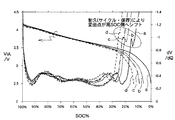
- FIG. 2 shows changes in battery voltage and dV / dQ with respect to SOC of LIB in the present embodiment.
- the horizontal axis represents SOC (%), and indicates the charged state as a percentage when the fully charged state is 100.
- the left vertical axis is the voltage (V), and the right vertical axis is the change amount dV / dQ of the voltage V and the capacity Q every predetermined time t.
- the initial SOC is high SOC, but the SOC value decreases at the end of discharge (that is, the end of discharge becomes closer to the right side in FIG. 2).
- the graphs indicated by symbols a to d are dV / dQ.
- dV / dQ the graphs indicated by symbols a to d.
- inflection point where dV / dQ changes sharply when SOC is 10% to 20% at the end of discharge.
- lithium ions are first released from graphite during discharge, and then lithium ions are released from SiO. Since graphite and SiO have different electrical resistances, and (graphite) ⁇ (SiO), lithium ions are released from graphite for high-rate currents such as hybrid vehicles (HEV) and plug-in hybrid vehicles (PHEV).
- HEV hybrid vehicles
- PHEV plug-in hybrid vehicles
- the graph a ⁇ graph b ⁇ graph c ⁇ graph d changes as the charge / discharge cycle progresses or the storage time becomes longer. That is, as the charge / discharge cycle progresses or the storage time becomes longer, the inflection point of dV / dQ at the end of discharge, that is, the inflection point of dV / dQ inherent to SiO due to SiO shifts to the higher SOC side. I will do it.
- the dV / dQ inflection point dV / dQ inherent to SiO is designed to be located outside the SOC usage range (for example, a range of 20% to 80%) during LIB manufacturing. After that, the inflection point of dV / dQ inherent to SiO is detected, and the SOC corresponding to the detected inflection point is shifted to the use range where it should be outside the use range. In such a case, the discharge is stopped at the SOC so as to suppress acceleration degradation.
- the discharge is stopped when the utilization rate of graphite is 80% or more and less than 100%, for example, about 80%, and then the charge / discharge cycle proceeds to a predetermined number of times as described above. It is preferable to detect an inflection point of dV / dQ inherent to SiO and stop the discharge in accordance with the detected inflection point.
- the inflection point of dV / dQ inherent to SiO is detected, but in order to distinguish it from other inflection points, the battery voltage is not more than a predetermined value, for example, the battery voltage is An inflection point at 3.5 V or less may be detected as a target inflection point. In FIG. 2, it should be noted that all the inflection points occur when the LIB voltage is 3.5 V or less.
- the dV / dQ when detecting the inflection point is calculated from the voltage change dV and the capacitance change dQ within a predetermined time, and the predetermined time is 1 msec to 1 min, for example, 0.1 sec to 1 sec. Can do.
- the inflection point of dV / dQ inherent to SiO is detected. Specifically, dV / dQ (t1) at a certain time and dV / dQ (at the next detection time) It can be detected as an inflection point when the difference in t2) is larger than a predetermined value, that is,
- the content of silicon or silicon compound is not particularly limited, but may be greater than 0 and not more than 10%, for example, 3% to 5% by weight% with respect to graphite.
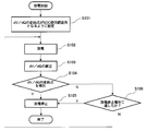
- FIG. 3 is a flowchart of the discharge control process in the present embodiment.
- dV / dQ at the time of discharging is measured, an inflection point of dV / dQ inherent to silicon or a silicon compound is detected, and an SOC corresponding to the inflection point is a predetermined SOC of LIB. It sets so that it may become out of use range (S101). For example, when the SOC usage range of LIB is set to 20% to 80%, the content of silicon or a silicon compound is adjusted so that the SOC corresponding to the inflection point is located at about 10%.
- known charging / discharging is performed in the in-vehicle LIB (S102). That is, discharging is performed to supply power from the LIB to the drive motor in accordance with the traveling state of the automobile, and charging is performed by supplying power to the LIB by engine power or regenerative braking.
- the charging / discharging of LIB is performed within the SOC usage range (for example, 20% to 80%). That is, when the SOC of the LIB reaches 20%, the discharge is stopped. Further, at the initial stage of the charge / discharge cycle, the discharge is stopped so that the utilization rate of graphite is 80% or more and less than 100%, and SiO is not used.
- dV / dQ is calculated during discharge in a predetermined control cycle (S103). That is, the voltage change dV and the capacitance change dQ within a predetermined time are detected, and dV / dQ is calculated.
- the capacity change dQ is calculated from the discharge current within a predetermined time.
- an inflection point of dV / dQ is detected (S104). Specifically, an inflection point is detected when the absolute value of the difference between dV / dQ in a certain control cycle and dV / dQ in the next control cycle is greater than a predetermined value, for example, 0.001 V / Ah. At this time, it is confirmed that the LIB voltage is not more than a predetermined value, for example, 3.5 V or less, and only when it is not more than the predetermined value, it may be detected as an inflection point of dV / dQ inherent to silicon or silicon compound.
- a predetermined value for example, 0.001 V / Ah
- the discharge control unit 123 stops the discharge of the nonaqueous electrolyte secondary battery (S105).
- the discharge is stopped at the preset discharge end voltage (Y in S106 and S105). If the preset discharge end voltage is not reached, the discharge is continued in S102 (N in S106). As shown in FIG. 2, as the charge / discharge cycle progresses or the storage time elapses, the inflection point of dV / dQ inherent to silicon or a silicon compound gradually shifts to the high SOC side.
- the inflection point of dV / dQ inherent to silicon or silicon compound means that lithium ions are released from the silicon or silicon compound.
- the silicon particles become fine powder, and the negative electrode Deterioration proceeds at an accelerated rate due to the expansion of the liquid and the occurrence of an unnecessary reaction with the electrolyte.
- the silicon particles become fine powder, which is caused by expansion of the negative electrode and generation of unnecessary reaction with the electrolytic solution.
- the acceleration of deterioration can be effectively suppressed.
- the discharge is controlled by paying attention to the inflection point of dV / dQ. Therefore, particularly in a hybrid vehicle, a plug-in hybrid vehicle, etc., relatively high input / output is required and the inflection is remarkable. This is particularly effective for applications where dots appear.
- the non-aqueous electrolyte secondary battery of this embodiment can also be applied to a drive power source of a mobile information terminal such as a mobile phone, a notebook computer, a smartphone, a tablet terminal, etc., particularly for applications that require high energy density. .
- the present invention can be used for a non-aqueous electrolyte secondary battery.
Landscapes
- Engineering & Computer Science (AREA)
- Chemical & Material Sciences (AREA)
- General Chemical & Material Sciences (AREA)
- Chemical Kinetics & Catalysis (AREA)
- Electrochemistry (AREA)
- Power Engineering (AREA)
- Manufacturing & Machinery (AREA)
- Life Sciences & Earth Sciences (AREA)
- Sustainable Development (AREA)
- Sustainable Energy (AREA)
- Transportation (AREA)
- Mechanical Engineering (AREA)
- Inorganic Chemistry (AREA)
- Materials Engineering (AREA)
- Secondary Cells (AREA)
- Battery Electrode And Active Subsutance (AREA)
- Charge And Discharge Circuits For Batteries Or The Like (AREA)
- Electric Propulsion And Braking For Vehicles (AREA)
Abstract
負極に黒鉛と珪素または珪素化合物を含有する非水電解質二次電池(10)の放電時の所定時間における電圧変化分dV及び容量変化分dQを用いてdV/dQを検出し、非水電解質二次電池の初期状態におけるdV/dQの変曲点をSOCの所定の使用範囲外に位置させる。その後、制御装置(12)は、充放電サイクルの進行に伴って、非水電解質二次電池(10)のdV/dQの変曲点を順次検出し、変曲点に対応するSOCを順次検出し、検出したSOCを使用範囲と比較し、SOCが使用範囲内までシフトした場合に当該SOCで放電停止する。充放電サイクル初期においては黒鉛の利用率を80%以上100%未満とし、かつ、珪素または珪素化合物を利用しないように放電制御する。
Description
本発明は非水電解質二次電池の放電制御装置及び方法に関し、特に車載用等の非水電解質二次電池の放電制御に関する。
近年のハイブリッド自動車(HEV)やプラグインハイブリッド自動車(PHEV)の重要性の高まりに伴い、車載用二次電池の高容量化とともに高入出力化に対するニーズが一層大きくなっている。
車載用非水電解質二次電池としては、リチウムイオン二次電池(LIB)が一般的に用いられている。LIBにおいて、車載用途として要求される入出力は、負極板の厚み、すなわち厚み方向のリチウムイオンの拡散により律速されることが知られており、負極板を薄くすることが高入出力化にとって効果的であることから、高容量化と高入出力化を同時に達成するためには、黒鉛に高容量化材料としての珪素または珪素化合物を混合して極板面積を大きくした負極が提案されている。
特許文献1には、珪素粒子核と、珪素粒子核の表面を被覆する炭素層からなるリチウム二次電池用負極材料が記載されている。
また、特許文献2には、珪素、珪素化合物または珪素と導電性物質からなる複合材料を負極活物質とする非水二次電池の製造に際し、組立後の電池を負極の電位が金属リチウムに対して100mVより高い電位で終止するように充電することが記載されている。
このように、車載用途としての高容量化及び高入出力化のためには炭素と珪素または珪素化合物を混合した負極が有効であるが、放電末期の領域を使用しすぎると、珪素微粒子が充放電で膨張収縮することにより微粉末化し、負極の膨張や電解液との不要な反応が発生するため、電池特性の劣化が加速してしまう問題がある。
すなわち、炭素と珪素または珪素化合物を混合した負極では、放電時にまず炭素からリチウムイオンが放出され、その後に珪素または珪素化合物からリチウムイオンが放出されるところ、放電末期の領域を使用しすぎると珪素または珪素化合物からのリチウムイオンの放出の寄与分が大きくなってしまい、電池特性の劣化が進んでしまう。
勿論、珪素または珪素化合物からリチウムイオンが放出される前に放電を終了することも理論的には考えられるが、放電を終了すべき適切なタイミングを見極めることは困難であり、不必要に早いタイミングで放電を終了してしまうのでは高容量化及び高入出力化の要請に反する結果を招く。
本発明は、上記従来の課題に鑑みなされたものであり、その目的は、劣化が加速してしまう放電末期の領域を使用しないように、当該領域を高速、簡易かつ確実に検知して放電を停止させ、もって高容量化及び高入出力化を図りつつ劣化を抑制し得る非水電解質二次電池の放電制御装置及び方法を提供することにある。
本発明は、負極に黒鉛と珪素または珪素化合物を含有する非水電解質二次電池の放電を制御する放電制御装置であって、充放電サイクル初期において前記黒鉛の利用率を80%以上100%未満とし、かつ、前記珪素または珪素化合物をほぼ利用しない(利用率を5%以下)で前記非水電解質二次電池の放電停止を制御する制御手段を備えることを特徴とする。
本発明の1つの実施形態では、前記非水電解質二次電池の電圧Vを検出する電圧検出手段と、前記非水電解質二次電池の電流Iを検出する電流検出手段と、前記電流検出手段の検出値に基づいて求められる所定時間における容量変化分dQと、前記電圧検出手段の検出値に基づいて求められる所定時間における容量変化分dVからdV/dQを算出する算出手段とをさらに有し、前記制御手段は、前記算出手段で算出されたdV/dQに基づいて放電停止を制御する。
本発明の他の実施形態では、前記制御手段は、前記dV/dQの変曲点に基づいて放電停止を制御する。
本発明のさらに他の実施形態では、前記制御手段は、前記非水電解質二次電池の電圧が所定値以下の場合に前記変曲点が算出された時に放電を停止する。
本発明のさらに他の実施形態では、前記制御手段は、制御周期における前記dV/dQの差分の絶対値が所定値を超えた変曲点が算出された場合に放電を停止する。
本発明のさらに他の実施形態では、前記非水電解質二次電池の初期状態では前記変曲点はSOCの所定の使用範囲外に存在しており、前記制御手段は、検出された前記変曲点が前記使用範囲内に存在する場合に前記変曲点に対応するSOCを用いて放電停止を制御する。
本発明のさらに他の実施形態では、前記所定時間は、1m秒以上1分以下である。
本発明のさらに他の実施形態では、前記珪素または珪素化合物の含有率は、0より大きく10%(重量%)以下である。
また、本発明は、負極に黒鉛と珪素または珪素化合物を含有する非水電解質二次電池の放電を制御する放電制御方法であって、充放電サイクル初期において前記黒鉛の利用率を80%以上100%未満とし、かつ、前記珪素または珪素化合物の利用率が5%以下となるように前記非水電解質二次電池の放電停止を制御することを特徴とする。
また、本発明は、負極に黒鉛と珪素または珪素化合物を含有する非水電解質二次電池の放電時の所定時間における電圧変化分dV及び容量変化分dQを用いてdV/dQを検出し、前記非水電解質二次電池の初期状態における前記dV/dQの変曲点をSOCの所定の使用範囲外に位置させ、前記非水電解質二次電池の前記dV/dQを順次算出し、前記dV/dQの変曲点が算出された時に放電停止させることを特徴とする。
本発明によれば、非水電解質二次電池の高容量化及び高入出力化を図りつつ、劣化を抑制することができ、充放電サイクル寿命を延長し得る。本発明は、dV/dQの変曲点が顕著に顕在化する高入出力の非水電解質二次電池、例えば車載用の非水電解質二次電池に好適に適用し得る。
以下、図面に基づき本発明の実施形態について、非水電解質二次電池としてリチウムイオン二次電池(LIB)を例にとり説明する。
<基本原理>
まず、本実施形態の基本原理について説明する。
まず、本実施形態の基本原理について説明する。
車載用の非水電解質二次電池には、高容量化と高入出力化が要求されるため、負極として黒鉛等の炭素と珪素(Si)または珪素化合物(SiO)を含有させたLIBが提案されている。
珪素または珪素化合物は、負極を薄くかつ大きくするために有効であるが、放電時に珪素からリチウムイオンが放出されてしまうと負極の劣化が加速してしまうため、充放電サイクル寿命を確保するためにはできるだけ珪素からのリチウムイオン放出量が所定の量10%以下で放電を停止すればよい。すなわち、充放電サイクル初期においては、黒鉛の利用率を80%以上100%未満とするとともに、珪素または珪素化合物をほぼ利用しないように(利用率5%以下)放電を停止すればよい。また、充放電サイクルが進み、黒鉛の劣化が進んで珪素または珪素化合物を利用せざるを得なくなった場合でも、その利用率をできるだけ制限(例えば10%程度に制限)すればよい。負極の黒鉛の利用率を一定程度に制限して充放電を行う技術は公知であるが、本実施形態では、黒鉛に珪素または珪素化合物を含有させて高容量化を図るものの、珪素または珪素化合物を意図的にできるだけ利用しないように放電を制御する点に留意すべきである。
他方、黒鉛等の炭素と珪素または珪素化合物では電気特性が異なるので、放電曲線の微分値、具体的には所定時間の電圧変化分dVと容量変化分dQの比dV/dQに着目すると、放電時に珪素または珪素化合物からリチウムイオンが放出されるようになるとdV/dQが顕著に変化し、変曲点として顕在化する。
そこで、充放電サイクル初期においては、黒鉛の利用率を80%以上100%未満とするとともに、珪素または珪素化合物を利用しないように放電を停止し、その後は、LIBのdV/dQの変曲点を監視し、この変曲点が出現するタイミングにおいてそれ以上放電を継続しないように放電を停止し、珪素または珪素化合物からのリチウムイオンの放出による負極の劣化を抑制するものである。
<構成>
次に、本実施形態の構成について説明する。
次に、本実施形態の構成について説明する。
図1は、本実施形態における非水電解質二次電池の放電制御装置の構成ブロック図である。
非水電解質二次電池10は、LIBであり、正極として例えばNCA系(Li(Ni-Co-Al)O2)、負極として例えば黒鉛と珪素化合物SiO(Siの微粒子がSiO2中に分散した構造)を混合したC/SiOが用いられる。なお、本発明は、これらの構造に限定されるものではなく、負極として黒鉛と珪素または珪素化合物を含有する任意の構造のLIBに適用し得る。
例えば、正極として、リチウム遷移金属複合酸化物を含む正極活物質と、導電剤と、結着剤をそれぞれ所定の重量比とし、分散媒と混合して正極合剤スラリーを作成し、アルミニウム箔の両面に塗布して形成することができ、リチウム遷移金属複合酸化物としては、具体的にはコバルト酸リチウム、マンガン酸リチウム、ニッケル酸リチウム、リチウムニッケルマンガン複合酸化物、リチウムニッケルコバルト複合酸化物等を用いることができ、これらのリチウム遷移金属複合酸化物にAl、Ti、Zr、Nb、B、W、Mg。Mo等を添加してもよい。導電剤としては、カーボンブラック、アセチレンブラック、ケッチェンブラック、黒鉛等の炭素粉末を単独で、あるいは2種以上組み合わせて用いてもよい。結着剤としては、フッ素系高分子、ゴム系高分子等が挙げられる。例えば、フッ素系高分子としてポリテトラフルオロエチレン(PTFE)、ポリフッ化ビニリデン(PVdF)、またはこれらの変性体等、ゴム系高分子としてエチレンープロピレンーイソプレン共重合体、エチレンープロピレンーブタジエン共重合体等が挙げられ、これらを単独で、あるいは2種以上を組み合わせて用いてもよい。負極としては、黒鉛と珪素または珪素化合物を含有する負極活物質と、増粘剤と、結着剤とを所定の重量比とし、水に分散させて負極合剤スラリーを作成し、銅箔の両面に塗布して形成することができ、結着剤としては、正極の場合と同様にPTFE等を用いることもできるが、スチレンーブタジエン共重合体(SBR)又はこの変性体等を用いてもよい。増粘剤としては、カルボキシメチルセルロース(CMC)等を用いることができる。
非水電解質の非水溶媒(有機溶媒)としては、カーボネート類、ラクトン類、エーテル類、ケトン類、エステル類等を用いることができ、これらの溶媒の2種以上を混合して用いることができる。例えば、エチレンカーボネート、プロピレンカーボネート、ブチレンカーボネート等の環状カーボネート、ジメチルカーボネート、エチルメチルカーボネート、ジエチルカーボネート等の鎖状カーボネートを用いることができる、環状カーボネートと鎖状カーボネートの混合溶媒を用いてもよい。
非水電解質の電解質塩としては、LiPF6、LiBF4、LICF3SO3等及びこれらの混合物を用いることができる。非水溶媒に対する電解質塩の溶解量は、例えば0.5~2.0mol/Lとすることができる。
セパレータとしては、ポリプロピレンやポリエチレンなどのポリオレフィン性の多孔質セパレータを用いることができる。ポリプロピレンとポリエチレンの多層構造としてもよく、ポリマー電解質をセパレータとして用いてもよい。
制御装置12は、プロセッサ及びメモリを備え、機能ブロックとして電流検出部120,電圧検出部121、dV/dQ算出部122、及び放電制御部123を備える。
電流検出部120及び電圧検出部121は、それぞれLIBの放電電流及び端子電圧を検出する。
dV/dQ算出部122は、LIBの放電時のdV/dQ、言い換えれば放電曲線の微分値を算出する。具体的には、dV/dQ算出部122は、電圧検出部121の検出電圧値から所定時間tにおける電圧の変化分dVと、電流検出部120が検出する放電電流値から所定時間tにおける容量変化分dQを検出し、これらを用いてdV/dQを算出する。
放電制御部123は、LIBの充放電を制御し、本実施形態では特にdV/dQに基づき放電の停止タイミングを制御する。具体的には、放電制御部123は、dV/dQ算出部122で算出されるdV/dQの値の変曲点が検出された場合は、検出SOCで放電を停止する。変曲点が検出されずに、あらかじめ設定された放電終止電圧に達した場合、その時点で放電停止する。
制御装置12のプロセッサは、プログラムメモリに記憶された処理プログラムに従い、dV/dQを算出する処理、dV/dQの変曲点を検出する処理、放電停止のタイミングを設定する処理の各処理を実行する。
<耐久に伴う変曲点のシフト>
図2は、本実施形態におけるLIBのSOCに対する電池電圧とdV/dQの変化を示す。図2において、横軸はSOC(%)であり、満充電状態を100としたときの充電状態を百分率で示す。左縦軸は電圧(V)であり、右縦軸は電圧Vと容量Qの所定時間t毎の変化量dV/dQである。
図2は、本実施形態におけるLIBのSOCに対する電池電圧とdV/dQの変化を示す。図2において、横軸はSOC(%)であり、満充電状態を100としたときの充電状態を百分率で示す。左縦軸は電圧(V)であり、右縦軸は電圧Vと容量Qの所定時間t毎の変化量dV/dQである。
放電初期は高SOCであるが、放電末期になるとSOCの値は低下する(すなわち、図2において右側にいくほど放電末期となる)。
図2において、符号a~dで示されるグラフはdV/dQであり、例えばグラフaに着目すると、SOCが放電末期の10%~20%においてdV/dQが急峻に変化する変曲点が存在する。図では、SOCの大きい方から小さい方に向けて変曲点として極大点と極小点が存在する。
既述したように、黒鉛とSiOを混合した負極では、放電時にまず黒鉛からリチウムイオンが放出され、その後にSiOからリチウムイオンが放出される。黒鉛とSiOでは電気抵抗が異なり、(黒鉛)<(SiO)であるため、ハイブリッド自動車(HEV)やプラグインハイブリッド自動車(PHEV)のように高レート電流に対しては、黒鉛からのリチウムイオン放出時と、SiOからのリチウムイオン放出時とで、電気抵抗の相違に起因してdV/dQに顕著な変化が生じ、結果として放電末期においてdV/dQに変曲点が出現する。
また、図2において、充放電サイクルが進むほど、あるいは保存時間が長くなるほど、グラフa→グラフb→グラフc→グラフdと変化していく。すなわち、充放電サイクルが進むほど、あるいは保存時間が長くなるほど、放電末期のdV/dQの変曲点、すなわちSiOに起因するSiOに固有のdV/dQの変曲点は、高SOC側にシフトしていく。
従って、SiOに固有のdV/dQの変曲点に着目し、当該変曲点の高SOC側へのシフト量を監視することで、LIBの負極がどの程度劣化しているかを定量評価することができる。
具体的には、例えば、LIBの製造時においてSiOに固有のdV/dQの変曲点dV/dQがSOCの使用範囲(例えば20%~80%の範囲)の領域外に位置するように設計し、その後、SiOに固有のdV/dQの変曲点を検出し、検出された変曲点に対応するSOCが、本来であれば使用域の領域外であるべきところ、使用範囲内までシフトした場合には、加速度的な劣化を抑制すべく当該SOCで放電を停止する。
ここで、充放電サイクルの初期においては、黒鉛の利用率を80%以上100%未満、例えば80%程度で放電を停止し、その後、充放電サイクルが所定回数まで進んだ後に、上記のようにSiOに固有のdV/dQの変曲点を検出し、検出した変曲点に応じて放電を停止するのが好適である。
また、本実施形態では、SiOに固有のdV/dQの変曲点を検出しているが、これ以外の他の変曲点と識別するために、電池電圧が所定値以下、例えば電池電圧が3.5V以下における変曲点を対象の変曲点として検出してもよい。図2において、変曲点は全てLIBの電圧が3.5V以下で生じている点に留意されたい。
また、変曲点を検出する際のdV/dQは、所定時間内における電圧変化分dV及び容量変化分dQから算出されるが、所定時間は1msec~1min、例えば0.1sec~1secとすることができる。
また、本実施形態では、SiOに固有のdV/dQの変曲点を検出しているが、具体的には、ある時刻におけるdV/dQ(t1)と、次の検出時刻におけるdV/dQ(t2)の差の大きさが所定値より大きい、すなわち|dV/dQ(t1)-dV/dQ(t2)|>所定値(例えば0.001V/Ah)を満たす場合に変曲点として検出できる。
さらに、本実施形態において、珪素または珪素化合物の含有量は特に限定されないが、黒鉛に対する重量%で0より大きく10%以下、例えば3%~5%とすることができる。
<放電制御フロー>
図3は、本実施形態における放電制御の処理フローチャートである。
図3は、本実施形態における放電制御の処理フローチャートである。
まず、LIBの製造時点において、放電時のdV/dQを測定し、珪素または珪素化合物に固有のdV/dQの変曲点を検出し、当該変曲点に対応するSOCがLIBの所定のSOC使用範囲外となるように設定する(S101)。例えば、LIBのSOC使用範囲を20%~80%とした場合に、変曲点に対応するSOCが10%程度に位置するように珪素または珪素化合物の含有量等を調整する。
次に、車載LIBにおいて公知の充放電を実行する(S102)。すなわち、自動車の走行状況に応じてLIBから駆動モータに電力を供給すべく放電し、エンジン動力あるいは回生制動によりLIBに電力を供給して充電する。LIBの充放電は、SOCの使用範囲(例えば、20%~80%)内で実行される。すなわち、LIBのSOCが20%に達すると、放電を停止する。また、充放電サイクル初期においては、黒鉛の利用率が80%以上100%未満となるように放電を停止し、SiOを利用しないようにする。
次に、所定の制御周期において放電時にdV/dQを算出する(S103)。すなわち、所定時間内における電圧変化dV及び容量変化dQを検出し、dV/dQを算出する。容量変化dQは、所定時間内における放電電流から算出される。
dV/dQを算出した後、dV/dQの変曲点を検出する(S104)。具体的には、ある制御周期におけるdV/dQと、次の制御周期におけるdV/dQの差の絶対値が所定値、例えば0.001V/Ahより大きい場合に変曲点として検出する。このとき、LIBの電圧が所定値以下、例えば3.5V以下であることを確認し、所定値以下の場合のみ珪素または珪素化合物固有のdV/dQの変曲点として検出してもよい。
変曲点を検出した場合(S104でY)、放電制御部123は非水電解質二次電池の放電を停止する(S105)。変曲点を検出しなかった場合(S104でN)で予め設定された放電終止電圧に達した場合、予め設定された放電終止電圧で放電を停止する(S106でYかつS105)。予め設定された放電終止電圧に達しない場合にはS102で放電を続行する(S106でN)。なお、図2に示すように、充放電サイクルが進み、あるいは保存時間が経過するに伴い、珪素または珪素化合物固有のdV/dQの変曲点は高SOC側に徐々にシフトしていく。従って、初期状態では変曲点に対応するSOCは使用範囲外に位置していたとしても、時間の経過とともに変曲点に対応するSOCが使用範囲内までシフトし得る。珪素または珪素化合物固有のdV/dQの変曲点は、珪素または珪素化合物からリチウムイオンが放出されることを意味しており、この領域での充放電を繰り返すと珪素粒子が微粉末化し、負極の膨張や電解液との不要な反応の発生により劣化が加速度的に進行してしまう。
このように、珪素または珪素化合物固有のdV/dQの変曲点に対応するSOCで放電を停止することで、珪素粒子が微粉末化し、負極の膨張や電解液との不要な反応の発生による劣化の加速を効果的に抑制することができる。
本実施形態では、dV/dQの変曲点に着目して放電を制御しているため、特にハイブリッド自動車やプラグインハイブリッド自動車等のように、相対的に高入出力が要求され顕著に変曲点が出現する用途に特に効果的である。勿論、本実施形態の非水電解質二次電池は、携帯電話、ノートパソコン、スマートフォン、タブレット端末等の移動情報端末の駆動電源で、特に高エネルギー密度が必要とされる用途に適用することもできる。
本発明は、非水電解質二次電池に利用することができる。
10 非水電解質二次電池
12 制御装置
120 電流検出部
121 電圧検出部
122 dV/dQ算出部
123 放電制御部
12 制御装置
120 電流検出部
121 電圧検出部
122 dV/dQ算出部
123 放電制御部
Claims (10)
- 負極に黒鉛と珪素または珪素化合物を含有する非水電解質二次電池の放電を制御する放電制御装置であって、
充放電サイクル初期において前記黒鉛の利用率を80%以上100%未満とし、かつ、
前記珪素または珪素化合物の利用率が5%以下とする、前記非水電解質二次電池の放電停止を制御する制御手段
を備えることを特徴とする非水電解質二次電池の放電制御装置。 - 前記非水電解質二次電池の電圧Vを検出する電圧検出手段と、
前記非水電解質二次電池の電流Iを検出する電流検出手段と、
前記電流検出手段の検出値に基づいて求められる所定時間における容量変化分dQと、
前記電圧検出手段の検出値に基づいて求められる所定時間における容量変化分dVからdV/dQを算出する算出手段と、
をさらに有し、
前記制御手段は、前記算出手段で算出されたdV/dQに基づいて放電停止を制御することを特徴とする請求項1記載の非水電解質二次電池の放電制御装置。 - 前記制御手段は、前記dV/dQの変曲点に基づいて放電停止を制御することを特徴とする請求項2記載の非水電解質二次電池の放電制御装置。
- 前記制御手段は、前記非水電解質二次電池の電圧が所定値以下の場合に前記変曲点が算出された時に放電停止することを特徴とする請求項3に記載の非水電解質二次電池の放電制御装置。
- 前記制御手段は、制御周期における前記dV/dQの差分の絶対値が所定値を超えた変曲点が算出された場合に放電を停止することを特徴とする請求項3に記載の非水電解質二次電池の放電制御装置。
- 前記非水電解質二次電池の初期状態では前記変曲点はSOCの所定の使用範囲外に存在しており、
前記制御手段は、検出された前記変曲点が前記使用範囲内に存在する場合に前記変曲点に対応するSOCを用いて放電停止を制御する
ことを特徴とする請求項3に非水電解質二次電池の放電制御装置。 - 前記所定時間は、1m秒以上1分以下であることを特徴とする請求項1~6のいずれかに記載の非水電解質二次電池の放電制御装置。
- 前記珪素または珪素化合物の含有率は、0より大きく10%(重量%)以下であることを特徴とする請求項1~7のいずれかに記載の非水電解質二次電池の放電制御装置。
- 負極に黒鉛と珪素または珪素化合物を含有する非水電解質二次電池の放電を制御する放電制御方法であって、
充放電サイクル初期において前記黒鉛の利用率を80%以上100%未満とし、かつ、前記珪素または珪素化合物の利用率が5%以下となるように前記非水電解質二次電池の放電停止を制御することを特徴とする非水電解質二次電池の放電制御方法。 - 負極に黒鉛と珪素または珪素化合物を含有する非水電解質二次電池の放電時の所定時間における電圧変化分dV及び容量変化分dQを用いてdV/dQを検出し、前記非水電解質二次電池の初期状態における前記dV/dQの変曲点をSOCの所定の使用範囲外に位置させ、
前記非水電解質二次電池の前記dV/dQを順次算出し、
前記dV/dQの変曲点が算出された時に放電停止させることを特徴とする非水電解質二次電池の放電制御方法。
Applications Claiming Priority (2)
| Application Number | Priority Date | Filing Date | Title |
|---|---|---|---|
| JP2015-015985 | 2015-01-29 | ||
| JP2015015985A JP2018041529A (ja) | 2015-01-29 | 2015-01-29 | 非水電解質二次電池の放電制御装置及び方法 |
Publications (1)
| Publication Number | Publication Date |
|---|---|
| WO2016120917A1 true WO2016120917A1 (ja) | 2016-08-04 |
Family
ID=56542585
Family Applications (1)
| Application Number | Title | Priority Date | Filing Date |
|---|---|---|---|
| PCT/JP2015/004516 Ceased WO2016120917A1 (ja) | 2015-01-29 | 2015-09-07 | 非水電解質二次電池の放電制御装置及び方法 |
Country Status (2)
| Country | Link |
|---|---|
| JP (1) | JP2018041529A (ja) |
| WO (1) | WO2016120917A1 (ja) |
Cited By (10)
| Publication number | Priority date | Publication date | Assignee | Title |
|---|---|---|---|---|
| WO2018074538A1 (ja) * | 2016-10-21 | 2018-04-26 | 株式会社Gsユアサ | 車両用蓄電装置、車両用放電システム、放電制御方法及び車両用蓄電素子 |
| CN108808140A (zh) * | 2018-04-26 | 2018-11-13 | 江西优特汽车技术有限公司 | 一种动力电池充电管理方法 |
| JP2019096461A (ja) * | 2017-11-22 | 2019-06-20 | 株式会社Gsユアサ | 蓄電装置及びその使用方法 |
| WO2019167475A1 (ja) * | 2018-02-28 | 2019-09-06 | パナソニックIpマネジメント株式会社 | 非水電解質二次電池の充電方法、及び非水電解質二次電池の充電システム |
| CN112166524A (zh) * | 2018-05-29 | 2021-01-01 | 松下知识产权经营株式会社 | 非水电解质二次电池的充电方法和非水电解质二次电池的充电系统 |
| CN116391287A (zh) * | 2022-03-31 | 2023-07-04 | 宁德新能源科技有限公司 | 电化学装置及控制方法、电化学装置管理系统、电子设备和介质 |
| CN116491006A (zh) * | 2022-03-31 | 2023-07-25 | 宁德新能源科技有限公司 | 电化学装置及其控制方法、电子设备和存储介质 |
| CN116724440A (zh) * | 2021-01-29 | 2023-09-08 | 松下知识产权经营株式会社 | 非水电解质二次电池的充电方法及充放电方法、以及非水电解质二次电池的充电系统 |
| CN116936969A (zh) * | 2022-03-31 | 2023-10-24 | 宁德新能源科技有限公司 | 电化学装置及其控制方法、电子设备和存储介质 |
| US12519335B2 (en) | 2020-03-30 | 2026-01-06 | Panasonic Energy Co., Ltd. | Secondary battery system |
Families Citing this family (4)
| Publication number | Priority date | Publication date | Assignee | Title |
|---|---|---|---|---|
| JP6965827B2 (ja) * | 2018-05-11 | 2021-11-10 | トヨタ自動車株式会社 | リチウムイオン電池の診断方法およびリチウムイオン電池の診断装置 |
| HUE061233T2 (hu) * | 2018-08-09 | 2023-05-28 | Lg Energy Solution Ltd | Eljárás cellában lévõ elektród elektrolittal való átitatottsága mértékének pontos vizsgálatára |
| WO2021191939A1 (ja) * | 2020-03-23 | 2021-09-30 | Tdk株式会社 | 二次電池の制御装置、電池パックおよび二次電池の制御方法 |
| JP7509119B2 (ja) * | 2021-11-15 | 2024-07-02 | トヨタ自動車株式会社 | 電池の劣化診断装置、及び電池の劣化診断方法 |
Citations (3)
| Publication number | Priority date | Publication date | Assignee | Title |
|---|---|---|---|---|
| JP2008186732A (ja) * | 2007-01-30 | 2008-08-14 | Nippon Carbon Co Ltd | リチウム二次電池用負極活物質、それを使用した負極及び製造方法 |
| JP2014225347A (ja) * | 2013-05-15 | 2014-12-04 | 信越化学工業株式会社 | 非水電解質二次電池用負極材及びその製造方法並びにリチウムイオン二次電池 |
| JP2014229583A (ja) * | 2013-05-27 | 2014-12-08 | 信越化学工業株式会社 | 負極活物質及び非水電解質二次電池並びにそれらの製造方法 |
-
2015
- 2015-01-29 JP JP2015015985A patent/JP2018041529A/ja active Pending
- 2015-09-07 WO PCT/JP2015/004516 patent/WO2016120917A1/ja not_active Ceased
Patent Citations (3)
| Publication number | Priority date | Publication date | Assignee | Title |
|---|---|---|---|---|
| JP2008186732A (ja) * | 2007-01-30 | 2008-08-14 | Nippon Carbon Co Ltd | リチウム二次電池用負極活物質、それを使用した負極及び製造方法 |
| JP2014225347A (ja) * | 2013-05-15 | 2014-12-04 | 信越化学工業株式会社 | 非水電解質二次電池用負極材及びその製造方法並びにリチウムイオン二次電池 |
| JP2014229583A (ja) * | 2013-05-27 | 2014-12-08 | 信越化学工業株式会社 | 負極活物質及び非水電解質二次電池並びにそれらの製造方法 |
Cited By (20)
| Publication number | Priority date | Publication date | Assignee | Title |
|---|---|---|---|---|
| WO2018074538A1 (ja) * | 2016-10-21 | 2018-04-26 | 株式会社Gsユアサ | 車両用蓄電装置、車両用放電システム、放電制御方法及び車両用蓄電素子 |
| CN109845015A (zh) * | 2016-10-21 | 2019-06-04 | 株式会社杰士汤浅国际 | 车辆用蓄电装置、车辆用放电系统、放电控制方法以及车辆用蓄电元件 |
| JPWO2018074538A1 (ja) * | 2016-10-21 | 2019-08-08 | 株式会社Gsユアサ | 車両用蓄電装置、車両用放電システム、放電制御方法及び車両用蓄電素子 |
| JP7205230B2 (ja) | 2016-10-21 | 2023-01-17 | 株式会社Gsユアサ | 車両用放電システム及び放電制御方法 |
| US11772511B2 (en) | 2016-10-21 | 2023-10-03 | Gs Yuasa International Ltd. | Vehicle-use energy storage apparatus, vehicle-use discharge system, discharge control method, and vehicle-use energy storage device |
| JP2019096461A (ja) * | 2017-11-22 | 2019-06-20 | 株式会社Gsユアサ | 蓄電装置及びその使用方法 |
| US11621130B2 (en) | 2017-11-22 | 2023-04-04 | Gs Yuasa International Ltd. | Energy storage apparatus and method of using the same |
| WO2019167475A1 (ja) * | 2018-02-28 | 2019-09-06 | パナソニックIpマネジメント株式会社 | 非水電解質二次電池の充電方法、及び非水電解質二次電池の充電システム |
| US11811255B2 (en) | 2018-02-28 | 2023-11-07 | Panasonic Intellectual Property Management Co., Ltd. | Charging method of non-aqueous electrolyte secondary battery, and charging system of non-aqueous electrolyte secondary battery |
| CN108808140A (zh) * | 2018-04-26 | 2018-11-13 | 江西优特汽车技术有限公司 | 一种动力电池充电管理方法 |
| CN112166524A (zh) * | 2018-05-29 | 2021-01-01 | 松下知识产权经营株式会社 | 非水电解质二次电池的充电方法和非水电解质二次电池的充电系统 |
| CN112166524B (zh) * | 2018-05-29 | 2024-03-15 | 松下知识产权经营株式会社 | 非水电解质二次电池的充电方法和非水电解质二次电池的充电系统 |
| US12519335B2 (en) | 2020-03-30 | 2026-01-06 | Panasonic Energy Co., Ltd. | Secondary battery system |
| CN116724440A (zh) * | 2021-01-29 | 2023-09-08 | 松下知识产权经营株式会社 | 非水电解质二次电池的充电方法及充放电方法、以及非水电解质二次电池的充电系统 |
| CN116491006A (zh) * | 2022-03-31 | 2023-07-25 | 宁德新能源科技有限公司 | 电化学装置及其控制方法、电子设备和存储介质 |
| CN116936969A (zh) * | 2022-03-31 | 2023-10-24 | 宁德新能源科技有限公司 | 电化学装置及其控制方法、电子设备和存储介质 |
| WO2023184336A1 (zh) * | 2022-03-31 | 2023-10-05 | 宁德新能源科技有限公司 | 电化学装置及其控制方法、电子设备和存储介质 |
| WO2023184339A1 (zh) * | 2022-03-31 | 2023-10-05 | 宁德新能源科技有限公司 | 电化学装置及控制方法、电化学装置管理系统、电子设备和介质 |
| CN116391287A (zh) * | 2022-03-31 | 2023-07-04 | 宁德新能源科技有限公司 | 电化学装置及控制方法、电化学装置管理系统、电子设备和介质 |
| CN116936969B (zh) * | 2022-03-31 | 2026-07-28 | 宁德新能源科技有限公司 | 电化学装置及其控制方法、电子设备和存储介质 |
Also Published As
| Publication number | Publication date |
|---|---|
| JP2018041529A (ja) | 2018-03-15 |
Similar Documents
| Publication | Publication Date | Title |
|---|---|---|
| JP2018041529A (ja) | 非水電解質二次電池の放電制御装置及び方法 | |
| JP5682955B2 (ja) | リチウム二次電池の制御システム、およびリチウム二次電池の状態検出方法 | |
| JP5810320B2 (ja) | リチウムイオン電池の充電方法及び電池搭載機器 | |
| JP6192738B2 (ja) | 電池モジュールおよび組電池 | |
| JP5057156B2 (ja) | リチウムイオン二次電池の充電方法及び充電システム | |
| KR101793849B1 (ko) | 비수전해질 이차 전지 및 조전지 | |
| EP3007261B1 (en) | Novel secondary battery | |
| TW201727990A (zh) | 鋰鍍覆的偵測方法,用於充電二次電池組的方法與設備,以及利用彼等的二次電池組系統 | |
| JP6898585B2 (ja) | 二次電池の状態推定方法および状態推定システム | |
| JP5924314B2 (ja) | 組電池 | |
| CN115004405B (zh) | 制造二次电池的方法 | |
| JP2017073331A (ja) | 二次電池装置 | |
| JP2018523911A (ja) | 非水電解液添加剤、これを含む非水電解液、及びこれを備えたリチウム二次電池 | |
| JP7356986B2 (ja) | 二次電池の充電システム | |
| US10601029B2 (en) | Positive electrode for nonaqueous electrolyte secondary battery and nonaqueous electrolyte secondary battery using the same | |
| JP6120083B2 (ja) | 非水電解液二次電池の製造方法 | |
| JP4714229B2 (ja) | リチウム二次電池 | |
| JP2009301850A (ja) | リチウム二次電池 | |
| JP6493762B2 (ja) | 電池システム | |
| CN106575746B (zh) | 非水电解质二次电池 | |
| JP2012016109A (ja) | リチウムイオン電池の充電方法および充電装置 | |
| KR102033670B1 (ko) | 리튬 이차전지용 바인더, 이를 포함하는 전극 및 리튬 이차전지 | |
| JP7070513B2 (ja) | 電池システム | |
| JP2014022317A (ja) | 非水系二次電池の充電方法 | |
| JP2017073929A (ja) | 充放電制御装置及び組電池装置 |
Legal Events
| Date | Code | Title | Description |
|---|---|---|---|
| 121 | Ep: the epo has been informed by wipo that ep was designated in this application |
Ref document number: 15879818 Country of ref document: EP Kind code of ref document: A1 |
|
| NENP | Non-entry into the national phase |
Ref country code: DE |
|
| NENP | Non-entry into the national phase |
Ref country code: JP |
|
| 122 | Ep: pct application non-entry in european phase |
Ref document number: 15879818 Country of ref document: EP Kind code of ref document: A1 |