WO2016117542A1 - モーター制御装置、シート搬送装置、及び画像形成装置 - Google Patents
モーター制御装置、シート搬送装置、及び画像形成装置 Download PDFInfo
- Publication number
- WO2016117542A1 WO2016117542A1 PCT/JP2016/051406 JP2016051406W WO2016117542A1 WO 2016117542 A1 WO2016117542 A1 WO 2016117542A1 JP 2016051406 W JP2016051406 W JP 2016051406W WO 2016117542 A1 WO2016117542 A1 WO 2016117542A1
- Authority
- WO
- WIPO (PCT)
- Prior art keywords
- pulse
- pulse width
- control
- unit
- speed
- Prior art date
- Legal status (The legal status is an assumption and is not a legal conclusion. Google has not performed a legal analysis and makes no representation as to the accuracy of the status listed.)
- Ceased
Links
Images


Classifications
-
- G—PHYSICS
- G03—PHOTOGRAPHY; CINEMATOGRAPHY; ANALOGOUS TECHNIQUES USING WAVES OTHER THAN OPTICAL WAVES; ELECTROGRAPHY; HOLOGRAPHY
- G03G—ELECTROGRAPHY; ELECTROPHOTOGRAPHY; MAGNETOGRAPHY
- G03G15/00—Apparatus for electrographic processes using a charge pattern
- G03G15/50—Machine control of apparatus for electrographic processes using a charge pattern, e.g. regulating differents parts of the machine, multimode copiers, microprocessor control
-
- H—ELECTRICITY
- H02—GENERATION; CONVERSION OR DISTRIBUTION OF ELECTRIC POWER
- H02P—CONTROL OR REGULATION OF ELECTRIC MOTORS, ELECTRIC GENERATORS OR DYNAMO-ELECTRIC CONVERTERS; CONTROLLING TRANSFORMERS, REACTORS OR CHOKE COILS
- H02P29/00—Arrangements for regulating or controlling electric motors, appropriate for both AC and DC motors
-
- B—PERFORMING OPERATIONS; TRANSPORTING
- B65—CONVEYING; PACKING; STORING; HANDLING THIN OR FILAMENTARY MATERIAL
- B65H—HANDLING THIN OR FILAMENTARY MATERIAL, e.g. SHEETS, WEBS, CABLES
- B65H5/00—Feeding articles separated from piles; Feeding articles to machines
- B65H5/06—Feeding articles separated from piles; Feeding articles to machines by rollers or balls, e.g. between rollers
-
- B—PERFORMING OPERATIONS; TRANSPORTING
- B65—CONVEYING; PACKING; STORING; HANDLING THIN OR FILAMENTARY MATERIAL
- B65H—HANDLING THIN OR FILAMENTARY MATERIAL, e.g. SHEETS, WEBS, CABLES
- B65H5/00—Feeding articles separated from piles; Feeding articles to machines
- B65H5/06—Feeding articles separated from piles; Feeding articles to machines by rollers or balls, e.g. between rollers
- B65H5/062—Feeding articles separated from piles; Feeding articles to machines by rollers or balls, e.g. between rollers between rollers or balls
-
- B—PERFORMING OPERATIONS; TRANSPORTING
- B65—CONVEYING; PACKING; STORING; HANDLING THIN OR FILAMENTARY MATERIAL
- B65H—HANDLING THIN OR FILAMENTARY MATERIAL, e.g. SHEETS, WEBS, CABLES
- B65H7/00—Controlling article feeding, separating, pile-advancing, or associated apparatus, to take account of incorrect feeding, absence of articles, or presence of faulty articles
-
- G—PHYSICS
- G03—PHOTOGRAPHY; CINEMATOGRAPHY; ANALOGOUS TECHNIQUES USING WAVES OTHER THAN OPTICAL WAVES; ELECTROGRAPHY; HOLOGRAPHY
- G03G—ELECTROGRAPHY; ELECTROPHOTOGRAPHY; MAGNETOGRAPHY
- G03G15/00—Apparatus for electrographic processes using a charge pattern
- G03G15/60—Apparatus which relate to the handling of originals
- G03G15/602—Apparatus which relate to the handling of originals for transporting
-
- G—PHYSICS
- G03—PHOTOGRAPHY; CINEMATOGRAPHY; ANALOGOUS TECHNIQUES USING WAVES OTHER THAN OPTICAL WAVES; ELECTROGRAPHY; HOLOGRAPHY
- G03G—ELECTROGRAPHY; ELECTROPHOTOGRAPHY; MAGNETOGRAPHY
- G03G15/00—Apparatus for electrographic processes using a charge pattern
- G03G15/65—Apparatus which relate to the handling of copy material
- G03G15/6529—Transporting
-
- H—ELECTRICITY
- H02—GENERATION; CONVERSION OR DISTRIBUTION OF ELECTRIC POWER
- H02P—CONTROL OR REGULATION OF ELECTRIC MOTORS, ELECTRIC GENERATORS OR DYNAMO-ELECTRIC CONVERTERS; CONTROLLING TRANSFORMERS, REACTORS OR CHOKE COILS
- H02P1/00—Arrangements for starting electric motors or dynamo-electric converters
- H02P1/16—Arrangements for starting electric motors or dynamo-electric converters for starting dynamo-electric motors or dynamo-electric converters
- H02P1/46—Arrangements for starting electric motors or dynamo-electric converters for starting dynamo-electric motors or dynamo-electric converters for starting an individual synchronous motor
-
- H—ELECTRICITY
- H02—GENERATION; CONVERSION OR DISTRIBUTION OF ELECTRIC POWER
- H02P—CONTROL OR REGULATION OF ELECTRIC MOTORS, ELECTRIC GENERATORS OR DYNAMO-ELECTRIC CONVERTERS; CONTROLLING TRANSFORMERS, REACTORS OR CHOKE COILS
- H02P1/00—Arrangements for starting electric motors or dynamo-electric converters
- H02P1/16—Arrangements for starting electric motors or dynamo-electric converters for starting dynamo-electric motors or dynamo-electric converters
- H02P1/46—Arrangements for starting electric motors or dynamo-electric converters for starting dynamo-electric motors or dynamo-electric converters for starting an individual synchronous motor
- H02P1/52—Arrangements for starting electric motors or dynamo-electric converters for starting dynamo-electric motors or dynamo-electric converters for starting an individual synchronous motor by progressive increase of frequency of supply to motor
-
- H—ELECTRICITY
- H02—GENERATION; CONVERSION OR DISTRIBUTION OF ELECTRIC POWER
- H02P—CONTROL OR REGULATION OF ELECTRIC MOTORS, ELECTRIC GENERATORS OR DYNAMO-ELECTRIC CONVERTERS; CONTROLLING TRANSFORMERS, REACTORS OR CHOKE COILS
- H02P27/00—Arrangements or methods for the control of AC motors characterised by the kind of supply voltage
- H02P27/04—Arrangements or methods for the control of AC motors characterised by the kind of supply voltage using variable-frequency supply voltage, e.g. inverter or converter supply voltage
- H02P27/06—Arrangements or methods for the control of AC motors characterised by the kind of supply voltage using variable-frequency supply voltage, e.g. inverter or converter supply voltage using DC to AC converters or inverters
- H02P27/08—Arrangements or methods for the control of AC motors characterised by the kind of supply voltage using variable-frequency supply voltage, e.g. inverter or converter supply voltage using DC to AC converters or inverters with pulse width modulation
-
- H—ELECTRICITY
- H02—GENERATION; CONVERSION OR DISTRIBUTION OF ELECTRIC POWER
- H02P—CONTROL OR REGULATION OF ELECTRIC MOTORS, ELECTRIC GENERATORS OR DYNAMO-ELECTRIC CONVERTERS; CONTROLLING TRANSFORMERS, REACTORS OR CHOKE COILS
- H02P3/00—Arrangements for stopping or slowing electric motors, generators, or dynamo-electric converters
- H02P3/06—Arrangements for stopping or slowing electric motors, generators, or dynamo-electric converters for stopping or slowing an individual dynamo-electric motor or dynamo-electric converter
- H02P3/18—Arrangements for stopping or slowing electric motors, generators, or dynamo-electric converters for stopping or slowing an individual dynamo-electric motor or dynamo-electric converter for stopping or slowing an AC motor
-
- H—ELECTRICITY
- H02—GENERATION; CONVERSION OR DISTRIBUTION OF ELECTRIC POWER
- H02P—CONTROL OR REGULATION OF ELECTRIC MOTORS, ELECTRIC GENERATORS OR DYNAMO-ELECTRIC CONVERTERS; CONTROLLING TRANSFORMERS, REACTORS OR CHOKE COILS
- H02P6/00—Arrangements for controlling synchronous motors or other dynamo-electric motors using electronic commutation dependent on the rotor position; Electronic commutators therefor
- H02P6/06—Arrangements for speed regulation of a single motor wherein the motor speed is measured and compared with a given physical value so as to adjust the motor speed
-
- B—PERFORMING OPERATIONS; TRANSPORTING
- B65—CONVEYING; PACKING; STORING; HANDLING THIN OR FILAMENTARY MATERIAL
- B65H—HANDLING THIN OR FILAMENTARY MATERIAL, e.g. SHEETS, WEBS, CABLES
- B65H2555/00—Actuating means
- B65H2555/20—Actuating means angular
- B65H2555/24—Servomotors
-
- B—PERFORMING OPERATIONS; TRANSPORTING
- B65—CONVEYING; PACKING; STORING; HANDLING THIN OR FILAMENTARY MATERIAL
- B65H—HANDLING THIN OR FILAMENTARY MATERIAL, e.g. SHEETS, WEBS, CABLES
- B65H2557/00—Means for control not provided for in groups B65H2551/00 - B65H2555/00
- B65H2557/20—Calculating means; Controlling methods
- B65H2557/23—Recording or storing data
-
- B—PERFORMING OPERATIONS; TRANSPORTING
- B65—CONVEYING; PACKING; STORING; HANDLING THIN OR FILAMENTARY MATERIAL
- B65H—HANDLING THIN OR FILAMENTARY MATERIAL, e.g. SHEETS, WEBS, CABLES
- B65H2557/00—Means for control not provided for in groups B65H2551/00 - B65H2555/00
- B65H2557/30—Control systems architecture or components, e.g. electronic or pneumatic modules; Details thereof
- B65H2557/33—Control systems architecture or components, e.g. electronic or pneumatic modules; Details thereof for digital control, e.g. for generating, counting or comparing pulses
-
- B—PERFORMING OPERATIONS; TRANSPORTING
- B65—CONVEYING; PACKING; STORING; HANDLING THIN OR FILAMENTARY MATERIAL
- B65H—HANDLING THIN OR FILAMENTARY MATERIAL, e.g. SHEETS, WEBS, CABLES
- B65H2801/00—Application field
- B65H2801/03—Image reproduction devices
- B65H2801/06—Office-type machines, e.g. photocopiers
-
- Y—GENERAL TAGGING OF NEW TECHNOLOGICAL DEVELOPMENTS; GENERAL TAGGING OF CROSS-SECTIONAL TECHNOLOGIES SPANNING OVER SEVERAL SECTIONS OF THE IPC; TECHNICAL SUBJECTS COVERED BY FORMER USPC CROSS-REFERENCE ART COLLECTIONS [XRACs] AND DIGESTS
- Y02—TECHNOLOGIES OR APPLICATIONS FOR MITIGATION OR ADAPTATION AGAINST CLIMATE CHANGE
- Y02P—CLIMATE CHANGE MITIGATION TECHNOLOGIES IN THE PRODUCTION OR PROCESSING OF GOODS
- Y02P70/00—Climate change mitigation technologies in the production process for final industrial or consumer products
- Y02P70/10—Greenhouse gas [GHG] capture, material saving, heat recovery or other energy efficient measures, e.g. motor control, characterised by manufacturing processes, e.g. for rolling metal or metal working
Definitions
- the present invention relates to a motor control device that controls a drive motor, a sheet conveying device including the motor control device, and an image forming apparatus including the sheet conveying device.
- an image forming apparatus such as a copying machine, a printer, a facsimile machine, and a multi-function peripheral has been provided with a plurality of rollers for conveying a sheet member on which an image is formed, and these rollers are driven by a drive motor.
- a drive motor for example, a servo motor such as a DC brushless motor may be employed.
- a configuration in which a DC brushless motor is used as a drive motor that drives a conveyance roller that conveys a sheet from a sheet feeding cassette is known (see Patent Document 1).
- a detector such as a rotary encoder is usually provided to detect the rotational speed of the drive motor.
- a motor driver is electrically connected to the servo motor, and a control device such as a CPU is electrically connected to the motor driver. Then, the control device outputs a control signal indicating a command speed for the servo motor to the motor driver.
- the motor driver generates a drive current by a PWM (Pulse Width Modulation) method based on the command speed indicated by the control signal and the actual rotation speed indicated by the detection result of the detector, and supplies the drive current to the servo motor.
- PWM Pulse Width Modulation
- a pulse signal including a plurality of pulses having a pulse width corresponding to a command speed for the servo motor is used as the control signal output from the control device to the motor driver.
- the motor driver detects the period of the pulse signal and the command speed based on a rising edge or a falling edge of the pulse signal (hereinafter, these edges are referred to as pulse edges).
- a process executed by the control device may be a process of stopping the output of the pulse signal to the motor driver.
- the motor driver cannot determine that the failure to detect the pulse edge is an instruction to stop the supply of the drive current to the servo motor. For this reason, the supply of the drive current cannot be stopped by the motor driver only by the control device stopping the output of the pulse signal to the motor driver.
- An object of the present invention is to provide a motor capable of stopping the supply of drive current to the drive motor at a timing at which supply of drive current to the drive motor such as the servomotor should be stopped while preventing an increase in the size of the circuit board.
- a control device, a sheet conveying device, and an image forming device are provided.
- a motor control device includes a pulse width detection unit, a speed control unit, a pulse width storage unit, an identical pulse detection unit, and a stop processing unit.
- the pulse width detection unit detects a pulse width of the pulse included in the pulse signal when a pulse signal including a plurality of pulses having a pulse width corresponding to a command speed for the drive motor is input.
- the speed control unit accelerates the rotational speed of the drive motor from zero to the target rotational speed based on the pulse signal in which the pulse width is set so that the command speed gradually increases to a predetermined target rotational speed.
- the rotation speed of the drive motor is reduced to zero based on the pulse signal in which the pulse width is set so that the command speed gradually decreases from the target rotation speed at the same acceleration magnitude as that in the acceleration control. Deceleration control to decelerate until.
- the pulse width storage unit stores the pulse width detected by the pulse width detection unit for the first pulse included in the pulse signal input during the acceleration control.
- the same pulse detection unit is configured to store the pulse width detected by the pulse width detection unit among the pulses included in the pulse signal input during the deceleration control. A pulse having the same pulse width as that of the first pulse is detected.
- the stop processing unit stops the control of the rotation speed of the drive motor by the speed control unit when the pulse having the same pulse width as the pulse width of the first pulse is detected by the same pulse detection unit.
- a sheet conveying device includes the motor control device and a conveying roller.
- the conveying roller rotates using a driving force transmitted from the driving motor controlled by the motor control device and conveys the sheet member.
- An image forming apparatus includes the sheet conveying device and an image forming unit.
- the image forming unit forms an image on the sheet member conveyed by the sheet conveying apparatus.
- a motor control device and a seat capable of stopping the supply of the drive current to the drive motor at a timing at which the supply of the drive current to the drive motor should be stopped while preventing an increase in the size of the circuit board.
- a conveyance device and an image forming apparatus can be provided.
- FIG. 1 is a diagram illustrating a configuration of an image forming apparatus according to an embodiment of the present invention.
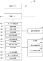
- FIG. 2 is a block diagram illustrating a configuration of a sheet conveying apparatus mounted on the image forming apparatus according to the embodiment of the present invention.
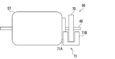
- FIG. 3 is a diagram illustrating the configuration of the drive motor and the rotation speed detection unit.
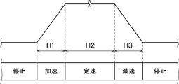
- FIG. 4 is a graph showing changes in the command speed of the drive motor.
- the upper diagram in FIG. 5 shows the signal waveform of the pulse signal output from the control unit
- the middle diagram in FIG. 5 is an enlarged view of the signal waveform shown in the upper diagram
- the lower diagram in FIG. 5 is shown in the upper diagram.
- It is a signal waveform diagram showing a reference clock signal for detecting a pulse width of a control pulse included in a pulse signal.
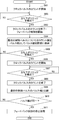
- FIG. 6 is a flowchart showing motor control processing by the motor control device.
- FIG. 1 is a diagram showing a configuration of an image forming apparatus 10 according to an embodiment of the present invention.
- the image forming apparatus 10 is a printer that prints an image on a sheet member P1 using toner.
- the image forming apparatus 10 is not limited to a printer having only a printing function.
- the present invention can be applied to a facsimile machine, a copying machine, or a multi-function machine having functions such as a printing function, a copying function, and a facsimile function.
- the image forming apparatus 10 prints an image on the sheet member P1 based on image data input from the outside via a network communication unit (not shown).
- the image forming apparatus 10 includes a paper feeding unit 15, an image forming unit 18, a fixing unit 19, a paper discharge unit 21, a control unit 90, and a sheet conveying device 100 (see FIG. 2).
- the paper feed unit 15 includes a paper feed tray 50, a pickup roller 51, and a paper feed roller pair 52.
- the sheet feed tray 50 accommodates a sheet member P1 on which an image is formed by the image forming unit 18.
- the sheet member P1 is fed from the paper feed tray 50 by the pickup roller 51 and the paper feed roller pair 52.
- the sheet member P1 fed by the pickup roller 51 is conveyed to the first conveyance path 26 formed on the downstream side in the sheet feeding direction of the sheet member P1 by the paper feed roller pair 52.
- the first transport path 26 is a transport path formed between the paper feed roller pair 52 and the image forming unit 18, and is formed by a transport guide (not shown) provided so as to face each other.
- a plurality of rotating rollers 44 are arranged in the first transport path 26.
- a rotating roller 45 is disposed on each of the rotating rollers 44 in contact with the outer peripheral surface of the rotating roller 44. When the rotating roller 44 rotates, the rotating roller 45 is also driven and rotated.
- the sheet member P ⁇ b> 1 fed to the first conveyance path 26 by the pair of paper feed rollers 52 is conveyed to the image forming unit 18 while being sandwiched between the rotation roller 44 and the rotation roller 45.
- the image forming unit 18 is provided near the end of the first transport path 26.
- the image forming unit 18 is an electrophotographic image forming unit that forms a toner image on the sheet member P1 based on image data input from the outside.
- the image forming unit 18 includes a photosensitive drum 31, a charging unit 32, a developing unit 33, an exposure unit 34, a transfer unit 35, and a cleaning unit 36.
- the charging unit 32 uniformly charges the surface of the photosensitive drum 31 to a predetermined potential. Further, a laser beam corresponding to the image data is scanned from the exposure unit 34 to the charged photosensitive drum 31. Thereby, an electrostatic latent image is formed on the photosensitive drum 31. Thereafter, the developing unit 33 attaches toner to the electrostatic latent image, and the toner image is developed on the photosensitive drum 31. Then, the toner image is transferred by the transfer unit 35 to the sheet member P ⁇ b> 1 that has been transported through the first transport path 26. The sheet member P1 on which the toner image is formed is conveyed to the second conveyance path 27 formed on the downstream side of the image forming unit 18 in the conveyance direction of the sheet member P1.
- the sheet member P1 sent from the image forming unit 18 to the second conveyance path 27 is conveyed to the fixing unit 19 through the second conveyance path 27.
- the fixing unit 19 fixes the toner image transferred to the sheet member P1 to the sheet member P1 by heat and pressure, and includes a heating roller 41 and a pressure roller 42. In the fixing unit 19, the toner is heated and melted by the heating roller 41 and fixed to the sheet member P1.
- the sheet member P1 on which the image is fixed by the fixing unit 19 is conveyed to a third conveyance path 28 formed downstream of the fixing unit 19 in the conveyance direction of the sheet member P1.
- the third transport path 28 is provided with a plurality of paper discharge roller pairs 23.
- the sheet member P1 sent to the third conveyance path 28 is conveyed upward through the third conveyance path 28 by the discharge roller pair 23 and discharged from the sheet discharge port 22 on the upper surface of the image forming apparatus 10. It is discharged to the paper section 21.
- the pickup roller 51, the paper feed roller pair 52, the rotation roller 44, the heating roller 41, the pressure roller 42, and the paper discharge roller pair 23 convey the sheet member P1 by rotating.
- these rollers are collectively referred to as a conveyance roller 150 (see FIG. 2).
- the transport roller 150 is rotationally driven by the driving force generated by the drive motor 57 being transmitted through a drive transmission mechanism such as a gear (not shown).
- the drive motor 57 is a servo motor such as a direct current brushless motor.
- the drive motor 57 is an inner rotor type in which a plurality of electromagnets are provided on a yoke, and a rotor (rotor) connected to a motor output shaft 48 (see FIG. 3) is provided inside the yoke.
- a DC brushless motor is used.
- the drive motor 57 is a servo motor whose rotational speed is feedback-controlled based on a speed signal indicating the actual rotational speed of the drive motor 57 detected by a rotational speed detector 99 (see FIG. 3) described later. It is not limited to a direct current brushless motor.
- the image forming apparatus 10 includes a rotation speed detection unit 99 that detects the actual rotation speed of the drive motor 57.
- the rotation speed detection unit 99 in this embodiment is a rotary encoder.
- the rotation speed detection unit 99 includes a pulse plate 70 having a disc shape and a photo interrupter 71.
- a large number of slits (not shown) extending in the radial direction are formed in a radial pattern with a rotation angle of 1 °, for example.
- the pulse plate 70 is fixed to the motor output shaft 48 of the drive motor 57.
- the photo interrupter 71 includes a light emitting unit 71A and a light receiving unit 71B that are opposed to each other with a predetermined interval.
- the pulse plate 70 passes through the gap between the light emitting unit 71A and the light receiving unit 71B.
- the signal levels of the signals output from the light receiving unit 71B are different. Therefore, when the pulse plate 70 rotates, a pulse signal is output from the light receiving unit 71B.
- the pulse signal output from the light receiving unit 71B is output to the motor control device 58 as the speed signal of the rotation speed detecting unit 99.
- the rotary encoder determines the rotation speed of the pulse plate 70 as the rotation angle. Detection is possible with a detection accuracy of 1 °.
- the sheet conveying apparatus 100 includes a motor control device 58 and a conveying roller 150.
- the motor control device 58 is electrically connected to the drive motor 57 and the control unit 90, receives a speed command from the control unit 90, and controls the drive current supplied to the drive motor 57.
- the conveying roller 150 rotates using the driving force transmitted from the driving motor 57 controlled by the motor control device 58 and conveys the sheet member P1.
- the motor control device 58 includes an electronic circuit such as an integrated circuit (ASIC) and an internal memory.
- the motor control device 58 may be a microcomputer having a CPU or the like as with the control unit 90.
- the motor control device 58 functions as a speed control unit 591.
- the speed control unit 591 generates the drive current by a PWM method (pulse width modulation method) using a pulse signal described later input from the control unit 90 and the speed signal output from the rotation speed detection unit 99. Feedback control to be supplied to the drive motor 57 is executed.
- the pulse signal is a control signal indicating a command speed for the drive motor 57. This command speed will be described later.
- the speed control unit 591 includes a phase comparison unit 592, a PWM control unit 593, and a drive circuit unit 594.
- the phase comparison unit 592 performs, for example, well-known PID (Proportional-Integral-Derivative) control based on the phase difference between the pulse signal input from the control unit 90 and the speed signal input from the rotation speed detection unit 99. Do.
- PID Proportional-Integral-Derivative
- the PWM control unit 593 generates a PWM signal having a duty ratio corresponding to the control amount obtained by the PID control by the phase comparison unit 592.
- the drive circuit unit 594 applies a voltage proportional to the duty ratio of the PWM signal output from the PWM control unit 593 to the drive motor 57 and supplies the drive motor 57 with the drive current.
- the control unit 90 is a microcomputer in which, for example, a CPU, a ROM, a RAM, and the like are stored in one integrated circuit.
- the CPU is a processor that executes various arithmetic processes.
- the ROM is a non-volatile storage unit in which information such as a control program for causing the CPU to execute various processes is stored in advance.
- the RAM is a volatile storage unit used as a primary storage memory (working area) for various processes executed by the CPU.
- the control unit 90 performs overall control of the operation of the image forming apparatus 10 by the CPU executing a program stored in the ROM.
- the ROM of the control unit 90 stores a processing program for causing the CPU to execute various processes.
- the control unit 90 functions as a pulse signal output unit 902 by executing a program using the CPU.
- a command speed storage unit 901 is included in the ROM.
- the rotation speed of the drive motor 57 is so-called trapezoid controlled by the motor control device 58. That is, the period during which the rotational speed of the drive motor 57 is controlled includes an acceleration control period H1, a constant speed control period H2, and a deceleration control period H3 (see FIG. 4).
- the acceleration control period H1 the rotational speed of the drive motor 57 is gradually increased from zero speed to a predetermined target rotational speed. Thereby, the conveyance roller 150 accelerates to a predetermined conveyance speed for conveying the sheet member P1 at a predetermined conveyance speed.
- the constant speed control period H2 after the acceleration control period H1 the rotational speed of the drive motor 57 is maintained at the target rotational speed.
- the conveyance roller 150 is maintained in the state which conveys the sheet member P1 at the said conveyance speed. Thereafter, in the deceleration control period H3, the rotational speed of the drive motor 57 is gradually decreased from the target rotational speed to zero speed. Thereby, the conveyance roller 150 decelerates from the conveyance speed and stops.
- the rotation speed of the drive motor 57 is commanded to the motor control device 58 from the control unit 90 in each period H1 to H3.
- the control unit 90 in the acceleration control period H1, is configured so that the rotational speed of the drive motor 57 gradually increases until the rotational speed of the drive motor 57 reaches the target rotational speed.
- the rotation speed is commanded to the motor control device 58 from a plurality of times. That is, the command speed from the control unit 90 to the motor control device 58 increases stepwise.
- the motor control device 58 is repeatedly commanded to rotate the drive motor 57 at a constant rotational speed from the control unit 90.
- a plurality of rotational speeds are transmitted from the control unit 90 to the motor controller 58 so that the rotational speed of the drive motor 57 gradually decreases until the rotational speed of the drive motor 57 reaches zero.
- the command speed from the control unit 90 to the motor control device 58 decreases stepwise.
- the command of the rotational speed of the drive motor 57 from the control unit 90 to the motor control device 58 is performed by the pulse signal output from the pulse signal output unit 902 to the motor control device 58.
- the pulse signal is a rectangular wave signal. In this specification, one rectangular wave, that is, a HIGH level signal that is a waveform portion from the rising edge E1 (see the middle diagram in FIG. 5) to the subsequent falling edge E2 (see the middle diagram in FIG. 5) is used as a control pulse.
- the pulse signal is a signal including a plurality of control pulses. The control pulse corresponds to the pulse of the present invention.
- the duty ratio of the pulse signal is a predetermined constant value regardless of the magnitude of the command speed, and the command speed depends on the period of the pulse signal, that is, the pulse width of the control pulse. Is to be commanded.
- the pulse signal output from the pulse signal output unit 902 during the acceleration control period H1 in which the command speed increases stepwise is the rotation of the drive motor 57 as described above. It is a signal for accelerating the speed.
- the period of the pulse signal and the pulse width of the control pulse are gradually shortened. That is, the pulse signal in the acceleration control period H1 is a rectangular wave signal having a plurality of control pulses in which the pulse width gradually decreases from zero speed to the target rotation speed.
- the pulse width of each control pulse of the pulse signal in the acceleration control period H1 indicates the command speed, that is, the rotational speed at which the drive motor 57 should rotate after one cycle.
- the pulse width gradually decreases. This is because the rotational speed at which the drive motor 57 should rotate after one cycle has elapsed is indicated by the pulse width of the immediately preceding control pulse. It is faster than that.
- the pulse signal output from the pulse signal output unit 902 during the deceleration control period H3 where the command speed decreases stepwise is a signal for reducing the rotational speed of the drive motor 57 as described above.
- the period of the pulse signal and the pulse width of the control pulse are gradually increased. That is, the pulse signal in the deceleration control period H3 is a rectangular wave signal having a plurality of control pulses in which the pulse width gradually increases from the target rotational speed to the speed zero.
- the pulse width of each control pulse of the pulse signal in the deceleration control period H3 indicates the command speed, that is, the rotational speed at which the drive motor 57 should rotate after one cycle. In the present embodiment, in the deceleration control period H3, the pulse width is gradually increased. This is because the rotational speed at which the drive motor 57 should rotate after one cycle has elapsed is indicated by the pulse width of the immediately preceding control pulse. It is slower than that.
- the pulse signal output from the pulse signal output unit 902 during the constant speed control period H2 where the command speed is constant is a signal for maintaining the rotational speed of the drive motor 57 at the target rotational speed.
- the period and the pulse width of the control pulse do not change. That is, the pulse signal in the constant speed control period H2 is a rectangular wave signal having a plurality of control pulses having the same pulse width.
- the pulse width of the control pulse corresponds to the command speed.
- the command speed storage unit 901 stores in advance the pulse width of each control pulse in each of the periods H1 to H3 as information on the command speed for the drive motor 57 in each of the periods H1 to H3.
- the pulse signal output unit 902 generates the pulse signal based on the command speed information stored in the command speed storage unit 901 and outputs the pulse signal to the motor control device 58.
- the speed control unit 591 of the motor control device 58 performs the acceleration control, the constant speed control, and the deceleration control.
- the pulse signal output unit 902 reduces the command speed from the target rotation speed to the same time as the time during which the command speed is increased from zero to the target rotation speed in the acceleration control period H1. Decrease until.
- the pulse signal output unit 902 reverses the control pulse having the same pulse width as each control pulse included in the pulse signal output in the acceleration control period H1 to the acceleration control period H1.
- the pulse width of the pulse signal in the acceleration control period H1 gradually decreases as the command speed increases, and the pulse width of the pulse signal in the deceleration control period H3 increases gradually as the command speed decreases.
- the pulse width of the control pulse that is finally output by the pulse signal output unit 902 in the deceleration control period H3 is the same as the pulse width of the control pulse that is output first by the pulse signal output unit 902 in the acceleration control period H1. It becomes width.
- the same pulse width includes not only the case where the pulse widths completely match, but also the case where the pulse width is within a predetermined error range.
- the process executed by the pulse signal output unit 902 of the control unit 90 includes a process of stopping the output of the pulse signal to the motor control device 58.
- the motor control device 58 cannot determine that the failure to detect the pulse edge of the control pulse is an instruction to stop the supply of the drive current to the drive motor 57. Therefore, the supply of the drive current cannot be stopped by the motor control device 58 simply by the pulse signal output unit 902 stopping the output of the pulse signal to the motor control device 58.
- the pulse signal output unit 902 determines that an instruction to stop the supply of the drive current to the drive motor 57 has been made on the condition that the motor control device 58 cannot detect the pulse edge during a predetermined standby time.
- the motor controller 58 may be configured. However, in order to stop the supply of the drive current, the motor control device 58 must wait for the standby time. Therefore, the timing for stopping the supply of the drive current is delayed from the timing that should be stopped. .
- the pulse signal output unit 902 outputs a stop signal instructing to stop the supply of the drive current to the motor control device 58 separately from the pulse signal.
- a new signal line for the stop signal is required, which causes an increase in the size of the circuit board.
- measures are taken to stop the supply of the drive current to the drive motor 57 at the timing to be stopped while preventing the circuit board from being enlarged by the following configuration.
- the motor control device 58 includes a pulse width detection unit 595, a pulse width storage unit 596, the same pulse detection unit 597, and a stop processing unit 598.
- the pulse width detector 595 detects the pulse width of the control pulse included in the pulse signal input from the controller 90.
- the pulse width detection unit 595 includes an edge detection unit 571, a clock output unit 572, and a count unit 573.
- the pulse width of the control pulse Pk is represented as Wk.
- the edge detector 571 detects the rising edge E1 and the falling edge E2 of the control pulse Pk.
- the clock output unit 572 outputs a reference clock signal having a shorter cycle than the control pulse Pk.
- the reference clock signal is a high-frequency (for example, 10 MHz) rectangular wave signal generated by a crystal oscillator (not shown).
- a waveform portion from a rising edge to a subsequent falling edge, that is, a HIGH level signal is referred to as a clock pulse.
- the count unit 573 is a clock included in the reference clock signal output from the clock output unit 572 between the time when the edge detection unit 571 detects the rising edge E1 of the control pulse and the time when the falling edge E2 is detected. Count the number of pulses. Since the number of clock pulses included in the reference clock signal is, for example, the same as the number of rising edges of the clock pulse, the counting unit 573 counts the number of rising edges of the clock pulse as the number of clock pulses. To do.
- the count value Ck by the count unit 573 is a value corresponding to the pulse width Wk of the control pulse Pk.
- the pulse width detector 595 detects the count value Ck from the counter 573 as the pulse width Wk of the control pulse Pk.
- the pulse width detection unit 595 stores the count value C1 for the control pulse P1 first input during the acceleration control period H1 in the pulse width storage unit 596 as the pulse width W1 of the control pulse P1.
- the stop processor 598 controls the rotational speed of the drive motor 57 by the speed controller 591. Stop.
- steps S601, S602,... represent processing procedures (step numbers).
- Step S601 When the edge detection unit 571 detects the rising edge E1 of the first control pulse P1, the count unit 573 starts counting the clock pulses included in the reference clock signal.
- Step S602 The edge detector 571 determines whether or not the falling edge E2 of the first control pulse P1 has been detected. If the edge detection unit 571 determines that the falling edge E2 of the first control pulse P1 is not detected (NO in step S602), the edge detection unit 571 executes the process of step S602 again. On the other hand, when it is determined that the falling edge E2 of the first control pulse P1 is detected (YES in step S602), the edge detection unit 571 executes the process of step S603.
- Step S603> The count unit 573 finishes counting the clock pulses included in the reference clock signal. Further, the speed control unit 591 generates the drive current by a PWM method (pulse width modulation method) using the pulse signal input from the control unit 90 and the speed signal input from the rotation speed detection unit 99. The feedback control to be supplied to the drive motor 57 is started.
- PWM method pulse width modulation method
- the pulse width detection unit 595 stores the count value C1 from the counting unit 573 in the pulse width storage unit 596 as the pulse width W1 of the first control pulse P1.
- Step S605 The edge detection unit 571 determines whether or not the rising edge E1 has been detected for the control pulse after the first control pulse P1. If it is determined that the rising edge E1 of the control pulse is not detected (NO in step S605), the edge detection unit 571 executes the process of step S605 again. On the other hand, when it is determined that the rising edge E1 of the control pulse has been detected (YES in step S605), the edge detection unit 571 executes the process of step S606.
- Step S606> The count unit 573 starts counting the clock pulses included in the reference clock signal.
- Step S607 The edge detection unit 571 determines whether or not the falling edge E2 of the control pulse has been detected. If it is determined that the falling edge E2 of the control pulse is not detected (NO in step S607), the edge detection unit 571 executes the process of step S607 again. On the other hand, when the edge detection unit 571 determines that the falling edge E2 of the control pulse has been detected (YES in step S607), the count unit 573 executes the process of step S608.
- Step S608> The count unit 573 finishes counting the clock pulses included in the reference clock signal. Accordingly, the pulse width of the control pulse is detected by the pulse width detector 595.
- Step S609 The same pulse detection unit 597 compares the pulse width detected in step S608 with the pulse width W1 of the first control pulse P1 stored in the pulse width storage unit 596.
- Step S611> The stop processing unit 598 stops the feedback control by the speed control unit 591.
- the supply of the drive current to the drive motor 57 can be stopped at the timing at which the supply of the drive current to the drive motor 57 should be stopped while preventing the circuit board from becoming large.
Landscapes
- Engineering & Computer Science (AREA)
- Power Engineering (AREA)
- Physics & Mathematics (AREA)
- General Physics & Mathematics (AREA)
- Mechanical Engineering (AREA)
- Microelectronics & Electronic Packaging (AREA)
- Control Of Electric Motors In General (AREA)
- Control Of Stepping Motors (AREA)
- Control Or Security For Electrophotography (AREA)
Abstract
Description
エッジ検出部571によって前記最初の制御パルスP1の立ち上がりエッジE1が検出されると、カウント部573は、前記基準クロック信号に含まれる前記クロックパルスのカウントを開始する。
エッジ検出部571は、前記最初の制御パルスP1の立ち下がりエッジE2を検出したか否かを判定する。エッジ検出部571は、前記最初の制御パルスP1の立ち下がりエッジE2を検出していないと判定した場合(ステップS602でNO)、再度ステップS602の処理を実行する。一方、エッジ検出部571は、前記最初の制御パルスP1の立ち下がりエッジE2を検出したと判定した場合(ステップS602でYES)、ステップS603の処理を実行する。
カウント部573は、前記基準クロック信号に含まれる前記クロックパルスのカウントを終了する。また、速度制御部591は、制御部90から入力される前記パルス信号と回転速度検出部99から入力される前記速度信号とを用いてPWM方式(パルス幅変調方式)により前記駆動電流を生成して駆動モーター57に供給するフィードバック制御の実行を開始する。
パルス幅検出部595は、カウント部573によるカウント値C1を前記最初の制御パルスP1のパルス幅W1としてパルス幅記憶部596に格納する。
エッジ検出部571は、前記最初の制御パルスP1の後の制御パルスについて立ち上がりエッジE1を検出したか否かを判定する。エッジ検出部571は、前記制御パルスの立ち上がりエッジE1を検出していないと判定した場合(ステップS605でNO)、再度ステップS605の処理を実行する。一方、エッジ検出部571は、前記制御パルスの立ち上がりエッジE1を検出したと判定した場合(ステップS605でYES)、ステップS606の処理を実行する。
カウント部573は、前記基準クロック信号に含まれる前記クロックパルスのカウントを開始する。
エッジ検出部571は、前記制御パルスの立ち下がりエッジE2を検出したか否かを判定する。エッジ検出部571は、前記制御パルスの立ち下がりエッジE2を検出していないと判定した場合(ステップS607でNO)、再度ステップS607の処理を実行する。一方、エッジ検出部571は、前記制御パルスの立ち下がりエッジE2を検出したと判定した場合(ステップS607でYES)、カウント部573は、ステップS608の処理を実行する。
カウント部573は、前記基準クロック信号に含まれる前記クロックパルスのカウントを終了する。これにより、パルス幅検出部595によって前記制御パルスのパルス幅が検出される。
同一パルス検出部597は、ステップS608において検出された前記パルス幅と、パルス幅記憶部596に格納された前記最初の制御パルスP1のパルス幅W1とを比較する。
同一パルス検出部597は、ステップS608で検出された前記パルス幅が前記最初の制御パルスP1のパルス幅W1と同一のパルス幅では無いと判定した場合には(ステップS610でNO)、ステップS605の処理に戻る。一方、同一パルス検出部597がステップS608で検出された前記パルス幅がパルス幅W1と同一であると判定した場合には(ステップS610でYES)、モーター制御装置58は、ステップS611の処理を行う。
停止処理部598は、速度制御部591によるフィードバック制御を停止させる。
Claims (6)
- 駆動モーターに対する指令速度に応じたパルス幅のパルスを複数含むパルス信号が入力された場合に前記パルス信号に含まれる前記パルスのパルス幅を検出するパルス幅検出部と、
前記指令速度が予め定められた目標回転速度まで漸増するように前記パルス幅が設定された前記パルス信号に基づいて前記駆動モーターの回転速度を零から前記目標回転速度まで加速させる加速制御と、前記指令速度が前記加速制御時と同じ加速度の大きさで前記目標回転速度から漸減するように前記パルス幅が設定された前記パルス信号に基づいて前記駆動モーターの回転速度を零まで減速させる減速制御とを行う速度制御部と、
前記加速制御時に入力される前記パルス信号に含まれる最初のパルスについて前記パルス幅検出部により検出された前記パルス幅を記憶するパルス幅記憶部と、
前記減速制御時に入力される前記パルス信号に含まれる前記パルスのうち、前記パルス幅検出部により検出される前記パルス幅が、前記パルス幅記憶部に記憶された前記最初のパルスのパルス幅と同一のパルス幅であるパルスを検出する同一パルス検出部と、
前記同一パルス検出部により前記最初のパルスのパルス幅と同一のパルス幅のパルスが検出されると、前記速度制御部による前記駆動モーターの回転速度の制御を停止させる停止処理部と、
を備えるモーター制御装置。 - 前記加速制御時における前記パルス信号は、前記指令速度の漸増に伴って前記パルス幅が漸減し、前記減速制御時における前記パルス信号は、前記指令速度の漸減に伴って前記パルス幅が漸増する請求項1に記載のモーター制御装置。
- 前記パルス信号のデューティ比は一定である請求項1に記載のモーター制御装置。
- 前記速度制御部は、前記パルス信号と前記駆動モーターの実回転速度を示す速度信号とを用いて、前記駆動モーターに供給される駆動電流のフィードバック制御を実行する請求項1に記載のモーター制御装置。
- 請求項1に記載のモーター制御装置と、
前記モーター制御装置により制御される前記駆動モーターから伝達される駆動力を用いて回転してシート部材を搬送する搬送ローラーと、
を備えるシート搬送装置。 - 請求項5に記載のシート搬送装置と、
前記シート搬送装置により搬送される前記シート部材に画像を形成する画像形成部と、
を備える画像形成装置。
Priority Applications (3)
| Application Number | Priority Date | Filing Date | Title |
|---|---|---|---|
| US15/116,954 US9735714B2 (en) | 2015-01-21 | 2016-01-19 | Motor controller, sheet conveying device, and image forming apparatus |
| CN201680000587.3A CN106416055B (zh) | 2015-01-21 | 2016-01-19 | 电动机控制装置、薄片体输送装置和图像形成装置 |
| JP2016546070A JP6012919B1 (ja) | 2015-01-21 | 2016-01-19 | モーター制御装置、シート搬送装置、及び画像形成装置 |
Applications Claiming Priority (2)
| Application Number | Priority Date | Filing Date | Title |
|---|---|---|---|
| JP2015-009727 | 2015-01-21 | ||
| JP2015009727 | 2015-01-21 |
Publications (1)
| Publication Number | Publication Date |
|---|---|
| WO2016117542A1 true WO2016117542A1 (ja) | 2016-07-28 |
Family
ID=56417084
Family Applications (1)
| Application Number | Title | Priority Date | Filing Date |
|---|---|---|---|
| PCT/JP2016/051406 Ceased WO2016117542A1 (ja) | 2015-01-21 | 2016-01-19 | モーター制御装置、シート搬送装置、及び画像形成装置 |
Country Status (4)
| Country | Link |
|---|---|
| US (1) | US9735714B2 (ja) |
| JP (1) | JP6012919B1 (ja) |
| CN (1) | CN106416055B (ja) |
| WO (1) | WO2016117542A1 (ja) |
Families Citing this family (5)
| Publication number | Priority date | Publication date | Assignee | Title |
|---|---|---|---|---|
| CN106068612B (zh) * | 2015-02-17 | 2018-08-07 | 京瓷办公信息系统株式会社 | 马达驱动装置、薄片体输送装置以及图像形成装置 |
| JP7291716B2 (ja) * | 2018-09-26 | 2023-06-15 | 東芝キヤリア株式会社 | 検出装置 |
| CN112551207B (zh) * | 2019-09-26 | 2023-04-18 | 京瓷办公信息系统株式会社 | 原稿输送装置 |
| JP7395333B2 (ja) * | 2019-11-27 | 2023-12-11 | 理想科学工業株式会社 | 搬送装置 |
| JP7409201B2 (ja) * | 2020-04-01 | 2024-01-09 | 京セラドキュメントソリューションズ株式会社 | 画像形成装置 |
Citations (5)
| Publication number | Priority date | Publication date | Assignee | Title |
|---|---|---|---|---|
| JP2000245192A (ja) * | 1999-02-19 | 2000-09-08 | Fujitsu Ltd | モータ駆動装置の調整方法及びモータ駆動装置並びに情報記憶装置 |
| US20040245953A1 (en) * | 2003-06-04 | 2004-12-09 | Peterson William A. | Methods and apparatus for dynamically reconfiguring a pulse width modulation approach |
| US20080111511A1 (en) * | 2006-11-13 | 2008-05-15 | Matsushita Electric Industrial Co. Ltd. | Electric power-assist system for manually-operated vehicle |
| JP2008259321A (ja) * | 2007-04-05 | 2008-10-23 | Matsushita Electric Ind Co Ltd | モータ制御回路 |
| JP2013099056A (ja) * | 2011-10-31 | 2013-05-20 | Ricoh Co Ltd | モータ駆動装置、シート搬送装置及び画像形成装置 |
Family Cites Families (4)
| Publication number | Priority date | Publication date | Assignee | Title |
|---|---|---|---|---|
| KR100672096B1 (ko) * | 1998-12-30 | 2007-01-19 | 코닌클리즈케 필립스 일렉트로닉스 엔.브이. | 다상 d.c. 모터의 구동 장치, 다상 d.c. 모터를 포함하는 구동 시스템 및 디스크 드라이브 |
| JP5504766B2 (ja) * | 2008-12-16 | 2014-05-28 | 富士ゼロックス株式会社 | 画像形成装置 |
| JP5825267B2 (ja) * | 2013-01-21 | 2015-12-02 | コニカミノルタ株式会社 | 画像処理装置およびモーターの回転制御方法 |
| JP6680504B2 (ja) * | 2015-10-14 | 2020-04-15 | シャープ株式会社 | シート搬送装置及びそれを備えた画像形成装置 |
-
2016
- 2016-01-19 JP JP2016546070A patent/JP6012919B1/ja active Active
- 2016-01-19 CN CN201680000587.3A patent/CN106416055B/zh not_active Expired - Fee Related
- 2016-01-19 WO PCT/JP2016/051406 patent/WO2016117542A1/ja not_active Ceased
- 2016-01-19 US US15/116,954 patent/US9735714B2/en not_active Expired - Fee Related
Patent Citations (5)
| Publication number | Priority date | Publication date | Assignee | Title |
|---|---|---|---|---|
| JP2000245192A (ja) * | 1999-02-19 | 2000-09-08 | Fujitsu Ltd | モータ駆動装置の調整方法及びモータ駆動装置並びに情報記憶装置 |
| US20040245953A1 (en) * | 2003-06-04 | 2004-12-09 | Peterson William A. | Methods and apparatus for dynamically reconfiguring a pulse width modulation approach |
| US20080111511A1 (en) * | 2006-11-13 | 2008-05-15 | Matsushita Electric Industrial Co. Ltd. | Electric power-assist system for manually-operated vehicle |
| JP2008259321A (ja) * | 2007-04-05 | 2008-10-23 | Matsushita Electric Ind Co Ltd | モータ制御回路 |
| JP2013099056A (ja) * | 2011-10-31 | 2013-05-20 | Ricoh Co Ltd | モータ駆動装置、シート搬送装置及び画像形成装置 |
Also Published As
| Publication number | Publication date |
|---|---|
| JPWO2016117542A1 (ja) | 2017-04-27 |
| JP6012919B1 (ja) | 2016-10-25 |
| US20170170754A1 (en) | 2017-06-15 |
| US9735714B2 (en) | 2017-08-15 |
| CN106416055A (zh) | 2017-02-15 |
| CN106416055B (zh) | 2018-04-20 |
Similar Documents
| Publication | Publication Date | Title |
|---|---|---|
| JP6012919B1 (ja) | モーター制御装置、シート搬送装置、及び画像形成装置 | |
| JP6173373B2 (ja) | モーター制御装置、シート搬送装置、及び画像形成装置 | |
| JP6245116B2 (ja) | シート搬送装置、及びシート搬送装置を備える画像形成装置 | |
| JP5747831B2 (ja) | モータ制御装置、搬送装置、画像形成装置、モータ制御方法およびプログラム | |
| JP6123477B2 (ja) | 搬送装置、搬送装置の制御方法及び制御プログラム | |
| JP6177451B2 (ja) | モーター駆動装置、シート搬送装置、及び画像形成装置 | |
| JP5142855B2 (ja) | 画像形成装置 | |
| US9505573B2 (en) | Sheet conveying device, image forming apparatus | |
| JP2016038481A (ja) | 画像形成装置 | |
| JP4920987B2 (ja) | 画像形成装置 | |
| JP6390341B2 (ja) | シート搬送装置、画像形成装置、シート特性推定方法、シート特性推定プログラム | |
| JP2014113042A (ja) | モータ制御装置、モータ制御システム、画像形成装置 | |
| JP4614873B2 (ja) | モータ制御装置及び画像形成装置 | |
| JP2017005901A (ja) | モータ駆動装置、画像形成装置、及びモータ駆動方法 | |
| JP2016021018A (ja) | 回転制御装置および制御方法 | |
| JP6332202B2 (ja) | 光走査装置、画像形成装置、異常検出方法 | |
| JP6149479B2 (ja) | モータ制御装置、画像形成装置、モータシステム、モータ制御方法及びプログラム | |
| JP2015018058A (ja) | 画像形成装置 | |
| JP2016092895A (ja) | モータ制御装置、駆動装置、画像形成装置、モータ制御方法およびプログラム | |
| JP2017128436A (ja) | シート搬送装置及びその制御方法、並びに画像形成装置 | |
| JP2008201547A (ja) | 用紙搬送装置及びこれを用いた画像形成装置 | |
| JP2014133644A (ja) | 用紙搬送装置、及び、これを備えた画像形成装置 |
Legal Events
| Date | Code | Title | Description |
|---|---|---|---|
| ENP | Entry into the national phase |
Ref document number: 2016546070 Country of ref document: JP Kind code of ref document: A |
|
| WWE | Wipo information: entry into national phase |
Ref document number: 15116954 Country of ref document: US |
|
| 121 | Ep: the epo has been informed by wipo that ep was designated in this application |
Ref document number: 16740149 Country of ref document: EP Kind code of ref document: A1 |
|
| NENP | Non-entry into the national phase |
Ref country code: DE |
|
| 122 | Ep: pct application non-entry in european phase |
Ref document number: 16740149 Country of ref document: EP Kind code of ref document: A1 |