WO2016117394A1 - ダイナモメータシステムの制御装置 - Google Patents
ダイナモメータシステムの制御装置 Download PDFInfo
- Publication number
- WO2016117394A1 WO2016117394A1 PCT/JP2016/050519 JP2016050519W WO2016117394A1 WO 2016117394 A1 WO2016117394 A1 WO 2016117394A1 JP 2016050519 W JP2016050519 W JP 2016050519W WO 2016117394 A1 WO2016117394 A1 WO 2016117394A1
- Authority
- WO
- WIPO (PCT)
- Prior art keywords
- integral
- dynamometer
- value
- engine
- shaft
- Prior art date
- Legal status (The legal status is an assumption and is not a legal conclusion. Google has not performed a legal analysis and makes no representation as to the accuracy of the status listed.)
- Ceased
Links
Images



Classifications
-
- G—PHYSICS
- G01—MEASURING; TESTING
- G01L—MEASURING FORCE, STRESS, TORQUE, WORK, MECHANICAL POWER, MECHANICAL EFFICIENCY, OR FLUID PRESSURE
- G01L3/00—Measuring torque, work, mechanical power, or mechanical efficiency, in general
- G01L3/02—Rotary-transmission dynamometers
- G01L3/04—Rotary-transmission dynamometers wherein the torque-transmitting element comprises a torsionally-flexible shaft
-
- G—PHYSICS
- G01—MEASURING; TESTING
- G01L—MEASURING FORCE, STRESS, TORQUE, WORK, MECHANICAL POWER, MECHANICAL EFFICIENCY, OR FLUID PRESSURE
- G01L25/00—Testing or calibrating of apparatus for measuring force, torque, work, mechanical power, or mechanical efficiency
- G01L25/006—Testing or calibrating of apparatus for measuring force, torque, work, mechanical power, or mechanical efficiency for measuring work or mechanical power or mechanical efficiency
-
- G—PHYSICS
- G01—MEASURING; TESTING
- G01L—MEASURING FORCE, STRESS, TORQUE, WORK, MECHANICAL POWER, MECHANICAL EFFICIENCY, OR FLUID PRESSURE
- G01L3/00—Measuring torque, work, mechanical power, or mechanical efficiency, in general
- G01L3/24—Devices for determining the value of power, e.g. by measuring and simultaneously multiplying the values of torque and revolutions per unit of time, by multiplying the values of tractive or propulsive force and velocity
- G01L3/242—Devices for determining the value of power, e.g. by measuring and simultaneously multiplying the values of torque and revolutions per unit of time, by multiplying the values of tractive or propulsive force and velocity by measuring and simultaneously multiplying torque and velocity
-
- G—PHYSICS
- G01—MEASURING; TESTING
- G01M—TESTING STATIC OR DYNAMIC BALANCE OF MACHINES OR STRUCTURES; TESTING OF STRUCTURES OR APPARATUS, NOT OTHERWISE PROVIDED FOR
- G01M15/00—Testing of engines
- G01M15/04—Testing internal-combustion engines
-
- G—PHYSICS
- G06—COMPUTING OR CALCULATING; COUNTING
- G06F—ELECTRIC DIGITAL DATA PROCESSING
- G06F17/00—Digital computing or data processing equipment or methods, specially adapted for specific functions
- G06F17/10—Complex mathematical operations
Definitions
- the present invention relates to a control device for a dynamometer system.
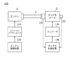
- FIG. 5 is a diagram illustrating a configuration of the dynamometer system 100.
- the dynamometer system 100 controls the engine E through a throttle actuator 110, an engine E as a specimen, a dynamometer D as a power absorber, a coupling shaft S coupled to the engine E and the dynamometer D, and the throttle actuator 110.
- An axial torque sensor 160 for detecting the axial torque (torsional torque) of the coupling portion.
- the engine control device 120 controls the output of the engine E in a predetermined manner for each test item, and the dynamo control device 140 controls the rotational speed of the dynamometer D based on the output of the encoder 150 and the shaft torque sensor 160. And torque are controlled (for example, refer to Patent Documents 1 and 2).
- FIG. 6 is a diagram showing a change in the number of revolutions at the time of starting the engine when the conventional system 100 realizes the no-load state. More specifically, it is a diagram showing a change in the rotational speed at the time of starting the engine when the shaft torque command value input to the dynamo control device 140 is set to 0 so that no torsional torque is generated in the conventional system 100.
- the measurement result by the system 100 that is, the rotation speed measured by the encoder 150 is indicated by a thin solid line.
- the rotational speed measured with the engine E and the coupling shaft S disconnected and the engine E in a no-load state that is, an ideal value at the time of no-load control is indicated by a thick broken line.
- the shaft torque sensor 160 of the coupled shaft S is simply controlled by setting the shaft torque command value to 0 [Nm] and the detected value of the shaft torque sensor to 0 [Nm].
- the inertia of the portion on the engine E side must be borne by the engine E, the engine speed at the time of starting becomes smaller than an ideal value corresponding to the no-load state.
- the position of the shaft torque sensor 160 is closer to the crankshaft side of the engine E, the inertia of the coupling shaft S can be borne by the dynamometer D.
- the closer the shaft torque sensor 160 is to the engine E the more easily the heat of the engine E is transmitted, so the influence of the change in the measured value due to the temperature drift increases.
- the closer the shaft torque sensor 160 is to the engine E the easier the vibration of the engine E is transmitted, and the measurement accuracy decreases.
- the position of the shaft torque sensor 160 is preferably closer to the dynamometer D than the engine E. Therefore, the above problem becomes significant.
- Patent Document 2 by multiplying the shaft torque command value of the shaft torque control circuit by multiplying the pseudo differential value (corresponding to angular acceleration) of the angular velocity of the dynamometer and a predetermined shaft inertia compensation value, Trying to solve the problem.
- the object of the present invention is to provide a control device for a dynamometer system that can accurately reproduce a no-load state when a specimen is started by a simple method.
- the present invention provides a dynamometer (for example, a dynamometer D described later), a specimen (for example, an engine E described later), a shaft connecting the dynamometer and the specimen (for example, a coupling shaft S described later, a shaft torque sensor (for example, shaft torque sensor 7 described later) for detecting torque acting on the shaft, and a rotation speed detector for detecting the rotation speed of the dynamometer (for example, And a control device (for example, a dynamo control device 6 to be described later) of a dynamometer system (for example, a dynamometer system 1 to be described later).
- a dynamometer for example, a dynamometer D described later
- a specimen for example, an engine E described later
- a shaft connecting the dynamometer and the specimen for example, a coupling shaft S described later, a shaft torque sensor (for example, shaft torque sensor 7 described later) for detecting torque acting on the shaft, and a rotation speed detector for detecting the rotation speed of
- the control device calculates an integral value of the deviation between the detected value of the shaft torque sensor and its command value, and multiplies the sum of the integral value and a predetermined correction value by an integral gain (for example, an integral gain Ki described later).
- An integral manipulated variable calculation unit for example, an integral manipulated variable calculation unit 611 described later
- a predetermined correction coefficient for example, an inertia compensation amount Jcmp described later
- a correction value calculation unit (for example, a correction value calculation unit 612 described later) that calculates the correction value by multiplication, and a non-integration operation amount that uses the output of a predetermined transfer function with the deviation as an input as a non-integration operation amount
- a calculation unit (for example, a non-integral operation amount calculation unit 613 described later) and a summation unit (for example, described later) that generates a torque current command signal for the dynamometer by adding the integration operation amount and the non-integration operation amount. Summation part of It includes a 14), a.
- the transfer function Ge0 (s) of the non-integral manipulated variable calculator is such that when Ki is the integral gain, s is a Laplace operator, and Ge (s) is input, the deviation is eliminated. And a transfer function that outputs a torque current command signal, and is determined so as to satisfy the following equation (1).
- the transfer function Ge (s) is preferably designed based on a control system design method called a ⁇ design method or an H ⁇ design method.
- the transfer function from the deviation between the detected value of the shaft torque sensor and its command value (hereinafter also simply referred to as “shaft torque deviation”) to the torque current command signal is expressed as an integral manipulated variable calculation unit. It is divided into the integral operation amount calculation unit. Then, the integral operation amount calculation unit calculates the sum of the integral value of the shaft torque deviation and a predetermined correction value, and multiplies this sum by the integral gain to calculate the integral operation amount.
- an apparent value from the specimen side is obtained by superimposing a correction value obtained by multiplying a detection value of the rotation speed detector by a predetermined correction coefficient on the integral value of the shaft torque deviation.
- Inertia compensation control can be performed so that the inertia of the specimen is reduced by an amount corresponding to the correction coefficient. Accordingly, since the burden on the specimen can be reduced as compared with the conventional one, the performance of only the specimen can be accurately evaluated in the racing test. Further, according to the present invention, if a transfer function Ge (s) having an axial torque control function is obtained by executing some design method, the above formula (1) satisfies this transfer function Ge (s). As described above, such an inertia compensation control function can be added only by separating the integrator and the non-integrator. In other words, the present invention does not require fine adjustment of parameters, which is necessary in the conventional technique such as Patent Document 2. Therefore, according to the present invention, the inertia compensation control function as described above can be added to the known transfer function having the shaft torque control function by a simple method.
- FIG. 1 It is a figure which shows the structure of the dynamometer system in which the dynamo control apparatus which concerns on one Embodiment of this invention was used. It is a block diagram which shows the structure of the control circuit of the axial torque control by the dynamo control apparatus which concerns on this embodiment. It is a block diagram which shows the structure of a controller provided with an axial torque control function. It is a figure which shows the result of the racing test by the dynamometer system which concerns on the said embodiment. It is a figure which shows the structure of the conventional dynamometer system. It is a figure which shows the result of the racing test by the conventional dynamometer system.
- FIG. 1 is a diagram illustrating a configuration of a dynamometer system 1 in which a dynamo control device 6 according to the present embodiment is used.
- the dynamometer system 1 includes an engine E as a specimen, a dynamometer D connected to the engine E via a coupling shaft S, an engine control device 5 that controls the engine E via a throttle actuator 2, and a dynamometer.
- An inverter 3 that supplies power to the meter D, a dynamo control device 6 that controls the dynamometer D via the inverter 3, a shaft torque sensor 7 that detects torsion torque of the coupling shaft S, and an output shaft SD of the dynamometer D And an encoder 8 for detecting the number of rotations.
- the coupling shaft S may be a mechanical part that is planned to be mounted on the vehicle together with the engine E such as a clutch, a transmission, and a propeller shaft.
- the engine E such as a clutch, a transmission, and a propeller shaft.
- a rigid test shaft may be used.
- the shaft torque sensor 7 detects a torsion torque acting on a portion of the coupling shaft S extending from the engine E to the dynamometer D closer to the dynamometer D than the engine E from, for example, a distortion amount of the coupling shaft S in the twist direction. Then, a signal substantially proportional to the detected value is transmitted to the dynamo control device 6.
- the engine control device 5 controls the output of the engine E in a predetermined manner after starting the engine E at a predetermined timing.
- the dynamo control device 6 corresponds to a torque value to be generated by the dynamometer D based on detection signals of the shaft torque sensor 7 and the encoder 8 so that the power generated by the engine E is absorbed in a predetermined manner.
- a torque current command signal is generated and input to the inverter 3.
- FIG. 2 is a block diagram showing a configuration of a control circuit for shaft torque control by the dynamo control device 6 according to the present embodiment.
- FIG. 3 is a diagram showing the configuration of the controller C that is the basis of the dynamo control device 6 of FIG.
- the controller C in FIG. 3 receives a torque current command signal that eliminates the deviation (SHTref ⁇ SHT, hereinafter simply referred to as “shaft torque deviation”) when the detected value SHT of the shaft torque sensor and the command value SHTref are input.
- a shaft torque control function for generating The dynamo control device 6 according to this embodiment shown in FIG. 2 is configured by adding an inertia compensation control function to the controller C having two degrees of freedom in FIG.
- the two-degree-of-freedom controller C having such an axial torque control function and the transfer functions Ge (s) and Gy (s) constituting the controller are shown, for example, in the embodiment of FIG. 6 of Japanese Patent No. 3775284 by the present applicant. Controller is used.
- the method for designing the controller C having the shaft torque control function and the transfer functions Ge (s) and Gy (s) constituting the controller C is not limited to the one based on the ⁇ design method disclosed in, for example, Japanese Patent No. 3775284. Absent.
- those designed based on other robust control design methods such as H ⁇ control may be used.
- the dynamo control device 6 includes a first controller 61 that receives the shaft torque deviation (SHTref ⁇ SHT) and the dynamo rotation speed (that is, the detected value DYw of the encoder), and the detected value SHT of the shaft torque sensor. , And a subtracter 63 that generates a torque current command signal DYTref by subtracting the output of the second controller 62 from the output of the first controller 61.
- the second controller 62 includes a transfer function Gy (s) that receives the detected value SHT of the shaft torque sensor.
- This transfer function Gy (s) is the same as the transfer function Gy (s) (see FIG. 3) constituting the controller C having the above-described shaft torque control function.
- the first controller 61 includes an integral operation amount calculation unit 611, a correction value calculation unit 612, a non-integral operation amount calculation unit 613, and a summation unit 614.
- the integral operation amount calculation unit 611 calculates an integral value of the shaft torque deviation (SHTref ⁇ SHT), calculates the sum of the integral value and the correction value calculated by the correction value calculation unit 612, and adds the integral gain to this sum.
- the integral operation amount is calculated by multiplying Ki.
- the correction value calculation unit 612 calculates a correction value (DYw ⁇ Jcmp) for the above-described integral operation amount by multiplying the dynamo rotation speed DYw by a predetermined inertia compensation amount Jcmp. As will be described in detail later, in the dynamo control device 6, by correcting the integral operation amount using such a correction value (DYw ⁇ Jcmp), the apparent inertia from the engine side becomes the inertia compensation amount Jcmp. An inertia compensation control function that is only small is provided.
- the non-integral manipulated variable calculator 613 includes a transfer function Ge0 (s).
- the non-integral manipulated variable calculator 613 sets the output obtained by inputting the shaft torque deviation (SHTref ⁇ SHT) to the transfer function Ge0 (s) as the non-integrated manipulated variable.
- the transfer function Ge0 (s) of the non-integrated manipulated variable calculator 613 separates the integrator having the integral gain Ki from the transfer function Ge (s) having the shaft torque control function so as to satisfy the following expression (2).
- the one obtained by is used. More specifically, this transfer function Ge (s) is together with the transfer function Ge (s) of the controller C having the shaft torque control function shown in FIG. 3, that is, the transfer function Gy (s) of the second controller 62 described above.
- the derived transfer function Ge (s) is used.
- the summation unit 614 adds the integral operation amount that is the output of the integral operation amount calculation unit 611 and the nonintegration operation amount that is the output of the non-integration operation amount calculation unit 613.
- the output of the summation unit 614 becomes part of the torque current command signal DYTref as described above.
- the dynamo control device 6 (see FIG. 2) configured as described above has an inertia compensation control function.
- the shaft connecting the engine and the dynamometer is a rigid body (spring coefficient Kc is ⁇ )
- the equation of motion of the controlled object is two inertias as shown in the following equations (3-1) to (3-3) Described by a system model.
- the appropriateness of the operation of the inertia compensation control function can be determined by analyzing the low frequency characteristics. Therefore, if only the portion contributing to the low frequency characteristics of the dynamo control device 6 shown in FIG. 2 is extracted and the command value SHTref is set to 0, the following equation (4) is obtained.
- Equation (5) the ratio of engine angular acceleration (s ⁇ EGw) to engine torque EGT (transfer function from engine torque to angular acceleration) is Equation (5) is obtained.
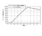
- FIG. 4 is a diagram showing changes in the engine speed at the time of engine start in the dynamometer system 1 using the dynamo control device 6 of FIG.
- the measurement result by the system using the dynamo control device 6 of FIG. 2 is shown by a thin solid line.
- the result of measurement when the engine and the shaft are separated and the engine is actually in a no-load state, that is, an ideal value at the time of inertia compensation control is indicated by a thick broken line.
- the thin solid line and the thick broken line almost coincide.
Landscapes
- Physics & Mathematics (AREA)
- General Physics & Mathematics (AREA)
- Engineering & Computer Science (AREA)
- Chemical & Material Sciences (AREA)
- Combustion & Propulsion (AREA)
- Theoretical Computer Science (AREA)
- Mathematical Physics (AREA)
- Data Mining & Analysis (AREA)
- Mathematical Analysis (AREA)
- Mathematical Optimization (AREA)
- Computational Mathematics (AREA)
- Pure & Applied Mathematics (AREA)
- Databases & Information Systems (AREA)
- Software Systems (AREA)
- General Engineering & Computer Science (AREA)
- Algebra (AREA)
- Testing Of Engines (AREA)
Abstract
Description
ダイナモメータシステム100は、供試体としてのエンジンEと、動力吸収体としてのダイナモメータDと、これらエンジンEとダイナモメータDと結合する結合軸Sと、スロットルアクチュエータ110を介してエンジンEを制御するエンジン制御装置120と、インバータ130を介してダイナモメータDを制御するダイナモ制御装置140と、ダイナモメータDの出力軸の回転数を検出するエンコーダ150と、結合軸SとダイナモメータDの出力軸との結合部の軸トルク(捩れトルク)を検出する軸トルクセンサ160と、を備える。

図1は、本実施形態に係るダイナモ制御装置6が用いられたダイナモメータシステム1の構成を示す図である。ダイナモメータシステム1は、供試体としてのエンジンEと、このエンジンEと結合軸Sを介して連結されたダイナモメータDと、スロットルアクチュエータ2を介してエンジンEを制御するエンジン制御装置5と、ダイナモメータDに電力を供給するインバータ3と、インバータ3を介してダイナモメータDを制御するダイナモ制御装置6と、結合軸Sの捩れトルクを検出する軸トルクセンサ7と、ダイナモメータDの出力軸SDの回転数を検出するエンコーダ8と、を備える。


図4は、図2のダイナモ制御装置6を利用したダイナモメータシステム1におけるエンジン始動時のエンジン回転数の変化を示す図である。図4には、図2のダイナモ制御装置6を利用したシステムによる測定結果を細実線で示す。また、エンジンとシャフトとを切り離しエンジンを実際に無負荷状態にして測定した場合の結果、すなわち慣性補償制御時の理想となる値を太破線で示す。図4に示すように、細実線と太破線とはほぼ一致する。上述のように慣性補償制御機能が追加されたダイナモ制御装置6を用いたシステムによれば、エンジン始動時にはダイナモメータでシャフト慣性が補償されるため、エンジン単体相当の始動波形が得られることが検証された。すなわち、本実施形態のダイナモ制御装置6を利用することにより、エンジンからみて無負荷状態が実現される。
6…ダイナモ制御装置
611…積分操作量演算部
612…補正値演算部
613…非積分操作量演算部
614…合算部
7…軸トルクセンサ
8…エンコーダ8(回転数検出器)
E…エンジン(供試体)
S…結合軸(軸)
Claims (2)
- ダイナモメータと、供試体と、前記ダイナモメータ及び前記供試体を連結する軸と、前記軸に作用するトルクを検出する軸トルクセンサと、前記ダイナモメータの回転数を検出する回転数検出器と、を備えたダイナモメータシステムの制御装置であって、
前記軸トルクセンサの検出値とその指令値との偏差の積分値を算出し、当該積分値と所定の補正値との和に積分ゲインを乗算し積分操作量を算出する積分操作量演算部と、
前記回転数検出器の検出値に所定の補正係数を乗算することにより前記補正値を算出する補正値演算部と、
前記偏差を入力とした所定の伝達関数の出力を非積分操作量とする非積分操作量演算部と、
前記積分操作量と前記非積分操作量とを合算することにより前記ダイナモメータに対するトルク電流指令信号を生成する合算部と、を備えることを特徴とするダイナモメータシステムの制御装置。
ここで、前記非積分操作量演算部の伝達関数Ge0(s)は、Kiを前記積分ゲインとし、sをラプラス演算子とし、Ge(s)を前記偏差が入力されると当該偏差が無くなるようなトルク電流指令信号を出力する伝達関数とし、下記式を満たすように定められる。

- 前記伝達関数Ge(s)は、μ設計法又はH∞設計方法と呼称される制御系設計方法に基づいて設計されることを特徴とする請求項1に記載のダイナモメータシステムの制御装置。
Priority Applications (2)
| Application Number | Priority Date | Filing Date | Title |
|---|---|---|---|
| US15/544,492 US10371589B2 (en) | 2015-01-19 | 2016-01-08 | Control device for dynamometer system |
| KR1020177018713A KR101841138B1 (ko) | 2015-01-19 | 2016-01-08 | 다이나모미터 시스템의 제어장치 |
Applications Claiming Priority (2)
| Application Number | Priority Date | Filing Date | Title |
|---|---|---|---|
| JP2015-007752 | 2015-01-19 | ||
| JP2015007752A JP6044649B2 (ja) | 2015-01-19 | 2015-01-19 | ダイナモメータシステムの制御装置 |
Publications (1)
| Publication Number | Publication Date |
|---|---|
| WO2016117394A1 true WO2016117394A1 (ja) | 2016-07-28 |
Family
ID=56416942
Family Applications (1)
| Application Number | Title | Priority Date | Filing Date |
|---|---|---|---|
| PCT/JP2016/050519 Ceased WO2016117394A1 (ja) | 2015-01-19 | 2016-01-08 | ダイナモメータシステムの制御装置 |
Country Status (4)
| Country | Link |
|---|---|
| US (1) | US10371589B2 (ja) |
| JP (1) | JP6044649B2 (ja) |
| KR (1) | KR101841138B1 (ja) |
| WO (1) | WO2016117394A1 (ja) |
Cited By (1)
| Publication number | Priority date | Publication date | Assignee | Title |
|---|---|---|---|---|
| WO2020121611A1 (ja) * | 2018-12-11 | 2020-06-18 | 株式会社明電舎 | 試験システムの軸トルク制御器及びフィードバック制御器の設計方法、並びにこの設計方法に基づいて設計される軸トルク制御器 |
Families Citing this family (12)
| Publication number | Priority date | Publication date | Assignee | Title |
|---|---|---|---|---|
| JP6044649B2 (ja) * | 2015-01-19 | 2016-12-14 | 株式会社明電舎 | ダイナモメータシステムの制御装置 |
| JP6629574B2 (ja) * | 2015-11-12 | 2020-01-15 | 株式会社エー・アンド・デイ | エンジン試験装置 |
| JP6149948B1 (ja) * | 2016-01-07 | 2017-06-21 | 株式会社明電舎 | 供試体特性推定方法及び供試体特性推定装置 |
| JP6659492B2 (ja) | 2016-07-27 | 2020-03-04 | 株式会社エー・アンド・デイ | エンジン試験装置 |
| JP6369596B1 (ja) * | 2017-05-09 | 2018-08-08 | 株式会社明電舎 | ダイナモメータシステムの制御装置 |
| CN107607234B (zh) * | 2017-10-24 | 2023-11-07 | 第一拖拉机股份有限公司 | 用于拖拉机变速箱内腔的扭矩检测装置及检测方法 |
| KR102256390B1 (ko) * | 2018-09-07 | 2021-05-26 | 메이덴샤 코포레이션 | 동력계 제어 장치 |
| JP7175445B2 (ja) * | 2019-01-16 | 2022-11-21 | 株式会社明電舎 | タイヤ試験装置の軸トルク制御器 |
| JP7175446B2 (ja) * | 2019-01-31 | 2022-11-21 | 株式会社明電舎 | タイヤ試験装置のタイヤ駆動制御装置 |
| JP7040581B1 (ja) * | 2020-09-29 | 2022-03-23 | 株式会社明電舎 | 試験システム |
| CN112985658B (zh) * | 2021-02-01 | 2022-05-13 | 温州技师学院 | 一种基于igbt技术的底盘测功设备 |
| KR102909942B1 (ko) * | 2023-06-13 | 2026-01-08 | 에이치엘만도 주식회사 | 전동기에 구비되는 센서의 센싱 지연을 검출하는 방법 및 장치 |
Citations (4)
| Publication number | Priority date | Publication date | Assignee | Title |
|---|---|---|---|---|
| JP2013053978A (ja) * | 2011-09-06 | 2013-03-21 | Meidensha Corp | エンジンベンチシステムの制御装置 |
| JP2013053977A (ja) * | 2011-09-06 | 2013-03-21 | Meidensha Corp | エンジンベンチシステムの制御装置 |
| JP5605127B2 (ja) * | 2010-09-27 | 2014-10-15 | 株式会社明電舎 | 軸トルク制御装置 |
| JP2014224722A (ja) * | 2013-05-15 | 2014-12-04 | 株式会社明電舎 | エンジンベンチシステム |
Family Cites Families (46)
| Publication number | Priority date | Publication date | Assignee | Title |
|---|---|---|---|---|
| US3324363A (en) * | 1964-04-30 | 1967-06-06 | Westinghouse Electric Corp | Motor control system for speed and tension of moving elongate material |
| JPS565127A (en) | 1979-06-27 | 1981-01-20 | Sumitomo Cement Co Ltd | Method and apparatus for calcining powdery stock material |
| JPS6033027A (ja) * | 1983-08-02 | 1985-02-20 | Horiba Ltd | シヤシダイナモメータの制御装置 |
| US4520681A (en) * | 1984-03-19 | 1985-06-04 | Jeff D. Moore | Apparatus for measuring torque on a rotating shaft |
| JPS62112028A (ja) * | 1985-11-09 | 1987-05-23 | Horiba Ltd | シャシダイナモメータシステムの制御装置 |
| US4870585A (en) * | 1987-10-13 | 1989-09-26 | Manzolini David B | Dynamometer engine performance analyzer system |
| JP2623758B2 (ja) * | 1988-09-05 | 1997-06-25 | 株式会社明電舎 | ディーゼルエンジンのトルク制御装置 |
| JP3084928B2 (ja) * | 1992-05-29 | 2000-09-04 | 三菱電機株式会社 | 電動機の位置制御装置 |
| EP0676681B1 (en) * | 1994-04-04 | 1999-11-10 | Kabushiki Kaisha Meidensha | Inertia lowering control apparatus for suppressing axial torsional vibration in two-mass resonant system |
| EP1184766B1 (en) * | 1999-06-04 | 2003-11-19 | Kabushiki Kaisha Yaskawa Denki Seisakusho | Position controller for motor |
| JP3918435B2 (ja) * | 2001-01-11 | 2007-05-23 | 株式会社明電舎 | 自動車部品の試験装置 |
| JP4997558B2 (ja) * | 2001-05-22 | 2012-08-08 | 株式会社ジェイテクト | 車両用操舵装置 |
| JP3508742B2 (ja) * | 2001-06-18 | 2004-03-22 | 日産自動車株式会社 | 電動モータを用いた車両の制振制御装置 |
| JP4322450B2 (ja) * | 2001-09-04 | 2009-09-02 | 三菱電機株式会社 | 電動式パワーステアリング制御装置 |
| JP3772721B2 (ja) * | 2001-10-11 | 2006-05-10 | 株式会社明電舎 | エンジンベンチシステムおよびエンジン特性の測定方法 |
| JP3775284B2 (ja) | 2001-11-08 | 2006-05-17 | 株式会社明電舎 | エンジンベンチシステムおよびエンジン特性の測定方法 |
| JP4321124B2 (ja) * | 2003-06-05 | 2009-08-26 | 株式会社明電舎 | 動力計測システムの電気慣性制御方式 |
| JP4547239B2 (ja) * | 2004-11-16 | 2010-09-22 | 株式会社エー・アンド・デイ | エンジン計測装置 |
| JP4283214B2 (ja) * | 2004-12-16 | 2009-06-24 | ファナック株式会社 | 機械先端点の制御装置 |
| JP4645231B2 (ja) * | 2005-02-28 | 2011-03-09 | シンフォニアテクノロジー株式会社 | 動力伝達系の試験装置とその制御方法 |
| JP4604813B2 (ja) | 2005-04-20 | 2011-01-05 | 株式会社明電舎 | ダイナモメータのスロットルアクチェータ |
| TWI327260B (en) * | 2005-05-31 | 2010-07-11 | Mitsubishi Electric Corp | Motor control device |
| JP5109342B2 (ja) * | 2006-11-15 | 2012-12-26 | 日本精工株式会社 | 電動パワーステアリング装置 |
| JP5169836B2 (ja) * | 2006-12-21 | 2013-03-27 | 株式会社安川電機 | 位置制御装置 |
| JP4835508B2 (ja) * | 2007-05-17 | 2011-12-14 | 株式会社明電舎 | 電気慣性制御方法 |
| JP4862758B2 (ja) | 2007-06-20 | 2012-01-25 | 株式会社明電舎 | ダイナモメータの制御装置 |
| JP4766039B2 (ja) * | 2007-11-30 | 2011-09-07 | 株式会社明電舎 | エンジンベンチシステムの制御方式 |
| JP5316151B2 (ja) * | 2009-03-25 | 2013-10-16 | シンフォニアテクノロジー株式会社 | 動力系の試験装置及びその制御方法 |
| JP5214578B2 (ja) * | 2009-12-02 | 2013-06-19 | 本田技研工業株式会社 | 動力装置の制御装置 |
| EP2580566B1 (en) | 2010-06-14 | 2019-11-13 | Rototest International AB | Method and device for dynamometer testing of a motor vehicle |
| JP5658530B2 (ja) * | 2010-10-20 | 2015-01-28 | 株式会社エー・アンド・デイ | エンジン試験装置 |
| JP5566469B2 (ja) * | 2010-10-27 | 2014-08-06 | 株式会社牧野フライス製作所 | 数値制御方法 |
| AT509381B1 (de) * | 2011-05-09 | 2012-04-15 | Avl List Gmbh | Prüfstand für dynamische prüfaufgaben an verbrennungskraftmaschinen, sowie verfahren zum betreiben eines derartigen prüfstandes |
| JP5790339B2 (ja) * | 2011-09-02 | 2015-10-07 | シンフォニアテクノロジー株式会社 | 動力伝達系の試験装置 |
| JP5605383B2 (ja) * | 2012-02-29 | 2014-10-15 | 株式会社明電舎 | ダイナモメータシステム |
| JP5304913B2 (ja) * | 2012-03-02 | 2013-10-02 | 株式会社明電舎 | ダイナモメータシステム |
| JP5344067B1 (ja) * | 2012-06-13 | 2013-11-20 | 株式会社明電舎 | 動力計システム |
| DE112014002813B4 (de) * | 2013-06-12 | 2021-05-06 | Mitsubishi Electric Corporation | Türeinrichtung und Türsteuerverfahren |
| JP5776731B2 (ja) * | 2013-06-19 | 2015-09-09 | 株式会社明電舎 | ドライブトレインの試験システム |
| JP5650814B1 (ja) * | 2013-07-05 | 2015-01-07 | ファナック株式会社 | フィードフォワード制御を備えたモータ制御装置 |
| JP5800001B2 (ja) * | 2013-10-07 | 2015-10-28 | 株式会社明電舎 | ダイナモメータシステム |
| JP6044647B2 (ja) * | 2015-01-13 | 2016-12-14 | 株式会社明電舎 | ダイナモメータの制御装置及びこれを用いた慣性モーメント推定方法 |
| JP6044649B2 (ja) * | 2015-01-19 | 2016-12-14 | 株式会社明電舎 | ダイナモメータシステムの制御装置 |
| JP6629574B2 (ja) * | 2015-11-12 | 2020-01-15 | 株式会社エー・アンド・デイ | エンジン試験装置 |
| JP6226021B2 (ja) * | 2016-04-28 | 2017-11-08 | 株式会社明電舎 | 試験システムのダイナモメータ制御装置 |
| JP6659492B2 (ja) * | 2016-07-27 | 2020-03-04 | 株式会社エー・アンド・デイ | エンジン試験装置 |
-
2015
- 2015-01-19 JP JP2015007752A patent/JP6044649B2/ja active Active
-
2016
- 2016-01-08 KR KR1020177018713A patent/KR101841138B1/ko active Active
- 2016-01-08 WO PCT/JP2016/050519 patent/WO2016117394A1/ja not_active Ceased
- 2016-01-08 US US15/544,492 patent/US10371589B2/en active Active
Patent Citations (4)
| Publication number | Priority date | Publication date | Assignee | Title |
|---|---|---|---|---|
| JP5605127B2 (ja) * | 2010-09-27 | 2014-10-15 | 株式会社明電舎 | 軸トルク制御装置 |
| JP2013053978A (ja) * | 2011-09-06 | 2013-03-21 | Meidensha Corp | エンジンベンチシステムの制御装置 |
| JP2013053977A (ja) * | 2011-09-06 | 2013-03-21 | Meidensha Corp | エンジンベンチシステムの制御装置 |
| JP2014224722A (ja) * | 2013-05-15 | 2014-12-04 | 株式会社明電舎 | エンジンベンチシステム |
Cited By (2)
| Publication number | Priority date | Publication date | Assignee | Title |
|---|---|---|---|---|
| WO2020121611A1 (ja) * | 2018-12-11 | 2020-06-18 | 株式会社明電舎 | 試験システムの軸トルク制御器及びフィードバック制御器の設計方法、並びにこの設計方法に基づいて設計される軸トルク制御器 |
| US11262274B2 (en) | 2018-12-11 | 2022-03-01 | Meidensha Corporation | Method for designing shaft torque controller and feedback controller of test system, and shaft torque controller designed on basis of same design method |
Also Published As
| Publication number | Publication date |
|---|---|
| US10371589B2 (en) | 2019-08-06 |
| JP6044649B2 (ja) | 2016-12-14 |
| JP2016133377A (ja) | 2016-07-25 |
| KR101841138B1 (ko) | 2018-03-22 |
| KR20170086663A (ko) | 2017-07-26 |
| US20170350775A1 (en) | 2017-12-07 |
Similar Documents
| Publication | Publication Date | Title |
|---|---|---|
| JP6044649B2 (ja) | ダイナモメータシステムの制御装置 | |
| JP5214578B2 (ja) | 動力装置の制御装置 | |
| JP5800001B2 (ja) | ダイナモメータシステム | |
| JP5708704B2 (ja) | エンジンベンチシステム | |
| JP6305283B2 (ja) | 動力装置の制御システム | |
| KR102045801B1 (ko) | 공시체 특성 추정 방법 및 공시체 특성 추정 장치 | |
| JP6007831B2 (ja) | 動力系の試験装置 | |
| US20210309206A1 (en) | Vehicle vibration control device | |
| JP6659492B2 (ja) | エンジン試験装置 | |
| JP6497408B2 (ja) | 電気慣性制御装置 | |
| US20190137361A1 (en) | Device for controlling dynamometer of test system | |
| JP6481792B2 (ja) | 動力系の試験装置 | |
| JP2013015386A (ja) | エンジンベンチシステムの制御方法 | |
| JP5605128B2 (ja) | 動力計の軸トルク制御装置 | |
| JP2011160574A (ja) | 電動機の速度制御装置 | |
| JP5895405B2 (ja) | エンジンベンチシステムの制御装置 | |
| JP2010043940A (ja) | 動力伝達系の試験装置およびその制御方法 | |
| JP2014142317A (ja) | 動力系の試験装置 | |
| JP2010112901A (ja) | シャシーダイナモ制御装置 | |
| JP6064694B2 (ja) | 動力系の試験装置 | |
| JP6026921B2 (ja) | 内燃機関の制御装置 | |
| JP4019709B2 (ja) | エンジンベンチシステム | |
| JP7633924B2 (ja) | モータ試験装置およびモータ試験方法 | |
| JP4946495B2 (ja) | 動力計測システムの電気慣性制御装置 |
Legal Events
| Date | Code | Title | Description |
|---|---|---|---|
| 121 | Ep: the epo has been informed by wipo that ep was designated in this application |
Ref document number: 16740001 Country of ref document: EP Kind code of ref document: A1 |
|
| ENP | Entry into the national phase |
Ref document number: 20177018713 Country of ref document: KR Kind code of ref document: A |
|
| WWE | Wipo information: entry into national phase |
Ref document number: 15544492 Country of ref document: US |
|
| NENP | Non-entry into the national phase |
Ref country code: DE |
|
| 122 | Ep: pct application non-entry in european phase |
Ref document number: 16740001 Country of ref document: EP Kind code of ref document: A1 |