WO2016111159A1 - 超伝導線、及び、超伝導コイル - Google Patents
超伝導線、及び、超伝導コイル Download PDFInfo
- Publication number
- WO2016111159A1 WO2016111159A1 PCT/JP2015/085765 JP2015085765W WO2016111159A1 WO 2016111159 A1 WO2016111159 A1 WO 2016111159A1 JP 2015085765 W JP2015085765 W JP 2015085765W WO 2016111159 A1 WO2016111159 A1 WO 2016111159A1
- Authority
- WO
- WIPO (PCT)
- Prior art keywords
- content
- superconducting
- less
- mass ppm
- ppm
- Prior art date
Links
Images


Classifications
-
- H—ELECTRICITY
- H01—ELECTRIC ELEMENTS
- H01B—CABLES; CONDUCTORS; INSULATORS; SELECTION OF MATERIALS FOR THEIR CONDUCTIVE, INSULATING OR DIELECTRIC PROPERTIES
- H01B12/00—Superconductive or hyperconductive conductors, cables, or transmission lines
- H01B12/02—Superconductive or hyperconductive conductors, cables, or transmission lines characterised by their form
- H01B12/04—Single wire
-
- B—PERFORMING OPERATIONS; TRANSPORTING
- B22—CASTING; POWDER METALLURGY
- B22D—CASTING OF METALS; CASTING OF OTHER SUBSTANCES BY THE SAME PROCESSES OR DEVICES
- B22D11/00—Continuous casting of metals, i.e. casting in indefinite lengths
-
- B—PERFORMING OPERATIONS; TRANSPORTING
- B22—CASTING; POWDER METALLURGY
- B22D—CASTING OF METALS; CASTING OF OTHER SUBSTANCES BY THE SAME PROCESSES OR DEVICES
- B22D11/00—Continuous casting of metals, i.e. casting in indefinite lengths
- B22D11/005—Continuous casting of metals, i.e. casting in indefinite lengths of wire
-
- B—PERFORMING OPERATIONS; TRANSPORTING
- B22—CASTING; POWDER METALLURGY
- B22D—CASTING OF METALS; CASTING OF OTHER SUBSTANCES BY THE SAME PROCESSES OR DEVICES
- B22D11/00—Continuous casting of metals, i.e. casting in indefinite lengths
- B22D11/12—Accessories for subsequent treating or working cast stock in situ
-
- C—CHEMISTRY; METALLURGY
- C22—METALLURGY; FERROUS OR NON-FERROUS ALLOYS; TREATMENT OF ALLOYS OR NON-FERROUS METALS
- C22C—ALLOYS
- C22C9/00—Alloys based on copper
-
- H—ELECTRICITY
- H01—ELECTRIC ELEMENTS
- H01B—CABLES; CONDUCTORS; INSULATORS; SELECTION OF MATERIALS FOR THEIR CONDUCTIVE, INSULATING OR DIELECTRIC PROPERTIES
- H01B12/00—Superconductive or hyperconductive conductors, cables, or transmission lines
-
- H—ELECTRICITY
- H01—ELECTRIC ELEMENTS
- H01B—CABLES; CONDUCTORS; INSULATORS; SELECTION OF MATERIALS FOR THEIR CONDUCTIVE, INSULATING OR DIELECTRIC PROPERTIES
- H01B12/00—Superconductive or hyperconductive conductors, cables, or transmission lines
- H01B12/02—Superconductive or hyperconductive conductors, cables, or transmission lines characterised by their form
-
- H—ELECTRICITY
- H01—ELECTRIC ELEMENTS
- H01F—MAGNETS; INDUCTANCES; TRANSFORMERS; SELECTION OF MATERIALS FOR THEIR MAGNETIC PROPERTIES
- H01F6/00—Superconducting magnets; Superconducting coils
- H01F6/06—Coils, e.g. winding, insulating, terminating or casing arrangements therefor
-
- H—ELECTRICITY
- H10—SEMICONDUCTOR DEVICES; ELECTRIC SOLID-STATE DEVICES NOT OTHERWISE PROVIDED FOR
- H10N—ELECTRIC SOLID-STATE DEVICES NOT OTHERWISE PROVIDED FOR
- H10N60/00—Superconducting devices
- H10N60/01—Manufacture or treatment
- H10N60/0128—Manufacture or treatment of composite superconductor filaments
-
- H—ELECTRICITY
- H01—ELECTRIC ELEMENTS
- H01B—CABLES; CONDUCTORS; INSULATORS; SELECTION OF MATERIALS FOR THEIR CONDUCTIVE, INSULATING OR DIELECTRIC PROPERTIES
- H01B12/00—Superconductive or hyperconductive conductors, cables, or transmission lines
- H01B12/02—Superconductive or hyperconductive conductors, cables, or transmission lines characterised by their form
- H01B12/06—Films or wires on bases or cores
-
- Y—GENERAL TAGGING OF NEW TECHNOLOGICAL DEVELOPMENTS; GENERAL TAGGING OF CROSS-SECTIONAL TECHNOLOGIES SPANNING OVER SEVERAL SECTIONS OF THE IPC; TECHNICAL SUBJECTS COVERED BY FORMER USPC CROSS-REFERENCE ART COLLECTIONS [XRACs] AND DIGESTS
- Y02—TECHNOLOGIES OR APPLICATIONS FOR MITIGATION OR ADAPTATION AGAINST CLIMATE CHANGE
- Y02E—REDUCTION OF GREENHOUSE GAS [GHG] EMISSIONS, RELATED TO ENERGY GENERATION, TRANSMISSION OR DISTRIBUTION
- Y02E40/00—Technologies for an efficient electrical power generation, transmission or distribution
- Y02E40/60—Superconducting electric elements or equipment; Power systems integrating superconducting elements or equipment
Definitions
- the present invention relates to a superconducting wire including a strand made of a superconductor and a superconducting stabilizer disposed in contact with the strand, and a superconducting coil made of the superconducting wire.
- the above-mentioned superconducting wire is used in fields such as MRI, NMR, particle accelerator, linear motor car, and power storage device.
- This superconducting wire has a multi-core structure in which a plurality of strands made of a superconductor such as Nb—Ti alloy and Nb 3 Sn are bundled with a superconducting stabilizer interposed.
- a tape-shaped superconducting wire in which a superconductor and a superconducting stabilizer are laminated is also provided.
- the above-described superconducting stabilizer is required to have a sufficiently low resistance at extremely low temperatures in order to efficiently bypass current.
- Residual resistance ratio (RRR) is widely used as an index indicating electric resistance at extremely low temperatures.
- the residual resistance ratio (RRR) is a ratio ⁇ 293K / ⁇ 4.2K with resistor [rho 4.2 K at room temperature resistance at (293K) ⁇ 293K and the liquid helium temperature (4.2 K), the residual resistance The higher the ratio (RRR), the better the performance as a superconducting stabilizer.
- Patent Documents 1 and 2 propose a Cu material having a high residual resistance ratio (RRR).
- Patent Document 1 proposes high-purity copper having a very low impurity concentration that defines the content of specific elements (Fe, P, Al, As, Sn, and S).
- Patent Document 2 proposes a Cu alloy obtained by adding a small amount of Zr to high-purity copper having a low oxygen concentration.
- JP 2011-236484 A Japanese Patent Laid-Open No. 05-025565
- the present invention has been made in view of the above-described circumstances, and can be manufactured at a relatively simple and inexpensive manufacturing process, and includes a superconducting stabilizer that has a sufficiently high residual resistance ratio (RRR). It is an object to provide a superconducting wire that can be used and a superconducting coil comprising the superconducting wire.
- RRR residual resistance ratio
- a superconducting wire comprising a superconducting stabilizer, wherein the superconducting stabilizer comprises a total of 3 additive elements selected from Ca, Sr, Ba, and rare earth elements. It is contained within the range of mass ppm or more and 400 mass ppm or less, and the balance is Cu and inevitable impurities, and the total concentration of the inevitable impurities excluding O, H, C, N, and S as gas components is 5 mass.
- rare earth elements are La, Ce, Pr, Nd, Pm, Sm, Eu, Gd, Tb, Dy, Ho, Er, Tm, Yb, Lu, Sc, and Y.
- the superconducting stabilizer has a total concentration of inevitable impurities excluding O, H, C, N, and S, which are gas components, of 5 ppm to 100 ppm. And a copper material containing a total of one or more additive elements selected from Ca, Sr, Ba, and rare earth elements within a range of 3 mass ppm to 400 mass ppm. Therefore, S, Se, and Te in copper are fixed as a compound, and the residual resistance ratio (RRR) of the superconducting stabilizer can be improved.
- RRR residual resistance ratio
- the superconducting stabilizer since the superconducting stabilizer is in electrical contact with the strand made of the superconductor, the superconductor can be used even when the superconducting state is broken in a part of the superconductor.
- the flowing current can be diverted to the superconducting stabilizer, and the entire superconducting wire can be prevented from transitioning to the normal state. Therefore, the superconducting wire can be used stably.
- copper is used in which the total concentration of inevitable impurities excluding O, H, C, N, and S, which are gas components, is 5 mass ppm or more and 100 mass ppm or less. Therefore, it is not necessary to increase the purity of copper excessively, the manufacturing process is simplified, and the manufacturing cost can be reduced.
- the superconducting stabilizer has a content of Fe as the inevitable impurities of 10 mass ppm or less and a content of Ni of 10 mass ppm or less.
- As content is 5 mass ppm or less, Ag content is 50 mass ppm or less, Sn content is 4 mass ppm or less, Sb content is 4 mass ppm or less, and Pb content is 6 mass ppm or less.
- the Bi material is preferably made of the copper material having a Bi content of 2 mass ppm or less and a P content of 3 mass ppm or less.
- elements of specific impurities such as Fe, Ni, As, Ag, Sn, Sb, Pb, Bi, and P have an action of reducing the residual resistance ratio (RRR). Therefore, by defining the contents of these elements as described above, it is possible to reliably improve the residual resistance ratio (RRR) of the superconducting stabilizer.
- the superconducting stabilizer is composed of a total content of S, Se and Te (X mass ppm) and Ca, Sr, Ba and rare earth elements.
- the ratio Y / X to the total content (Y mass ppm) of one or more selected additive elements selected from the copper material is in the range of 0.5 ⁇ Y / X ⁇ 100. Is preferred.
- the total content (X mass ppm) of S, Se, Te and the total content (Y mass ppm) of one or more additive elements selected from Ca, Sr, Ba, and rare earth elements Since the ratio Y / X is in the above-mentioned range, S, Se, Te in copper is a compound with one or more additive elements selected from Ca, Sr, Ba, and rare earth elements. It is possible to reliably fix the residual resistance ratio (RRR) due to S, Se, Te.
- RRR residual resistance ratio
- the superconducting stabilizer is composed of one or more additive elements selected from Ca, Sr, Ba, and rare earth elements, and S, Se.
- Te is preferably made of the copper material containing a compound containing one or more elements selected from Te.
- S, Se, and Te present in the copper are securely fixed by a compound with one or more additive elements selected from Ca, Sr, Ba, and rare earth elements.
- Te can reliably suppress a decrease in the residual resistance ratio (RRR).
- the superconducting stabilizer preferably has a residual resistance ratio (RRR) of 250 or more.
- the residual resistance ratio (RRR) of the superconducting stabilizer is relatively high at 250 or more, the resistance value at a very low temperature is sufficiently low, and the current flows when the superconducting state of the superconductor is broken. Can be sufficiently bypassed, and the normal state can be prevented from propagating throughout the superconductor.
- the superconducting stabilizer is preferably manufactured by a continuous casting and rolling method. In this case, since casting and rolling are carried out continuously, it is possible to obtain a long superconducting stabilizer with high production efficiency.
- the superconducting coil according to the second aspect of the present invention is characterized in that it has a structure including a winding portion in which the superconducting wire according to the first aspect described above is wound around the peripheral surface of the winding frame. Yes.
- the superconducting wire provided with the superconducting stabilizer having a high residual resistance ratio (RRR) is used, so that it can be used stably. .
- a superconducting wire that can be manufactured stably with a superconducting stabilizer having a sufficiently high residual resistance ratio (RRR) that can be manufactured at a relatively simple and inexpensive manufacturing process, and A superconducting coil comprising this superconducting wire can be provided.
- RRR residual resistance ratio
- superconducting wire 10 which is one embodiment of the present invention is explained with reference to the attached drawings.
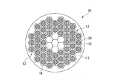
- the superconducting wire 10 in the present embodiment is disposed on a core portion 11, a plurality of filaments 12 disposed on the outer peripheral side of the core portion 11, and an outer peripheral side of the plurality of filaments 12. And an outer shell portion 13.
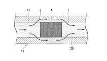
- the filament 12 described above has a structure in which a strand 15 made of a superconductor is covered with a superconducting stabilizer 20 while being in electrical contact, as shown in FIGS. 1 and 2. Yes. That is, the strand 15 made of a superconductor and the superconducting stabilizer 20 are in a state where electricity can be conducted.
- the superconducting stabilizer 20 is formed from a superconductor when the superconducting state is broken and a normal conduction region A is generated in a part of the strand 15 made of a superconductor. The current I flowing through the element wire 15 is temporarily bypassed.
- the superconducting stabilizer 20 is a range of 3 mass ppm or more and 400 mass ppm or less in total of one or more additive elements selected from Ca, Sr, Ba, and rare earth elements. And the balance is Cu and inevitable impurities, and the total concentration of inevitable impurities excluding gas components O, H, C, N, and S is 5 mass ppm to 100 mass ppm It is composed of materials.
- the copper material constituting the superconducting stabilizer 20 has a content of Fe, which is an inevitable impurity, of 10 ppm by mass or less, a content of Ni of 10 ppm by mass or less, and a content of As of 5 Mass ppm or less, Ag content is 50 mass ppm or less, Sn content is 4 mass ppm or less, Sb content is 4 mass ppm or less, Pb content is 6 mass ppm or less, Bi content is 2 The mass ppm or less and the P content are 3 mass ppm or less.
- the total content (X mass ppm) of S, Se, Te, and one or more selected from Ca, Sr, Ba, and rare earth elements is set in the range of 0.5 ⁇ Y / X ⁇ 100.
- the copper material constituting the superconducting stabilizer 20 includes one or more additive elements selected from Ca, Sr, Ba, and rare earth elements, and S, Se, Te. There is a compound containing one or more elements selected from: Furthermore, in this embodiment, the superconducting stabilizer 20 has a residual resistance ratio (RRR) of 250 or more.
- RRR residual resistance ratio
- One or more additive elements selected from Ca, Sr, Ba and rare earth elements Of the inevitable impurities contained in copper, S, Se, and Te are elements that greatly reduce the residual resistance ratio (RRR) by being dissolved in copper. For this reason, in order to improve the residual resistance ratio (RRR), it is necessary to eliminate the influence of these S, Se, and Te.
- one or more additive elements selected from Ca, Sr, Ba, and rare earth elements are elements that are highly reactive with S, Se, and Te, S, Se, Te, and a compound are included. By producing
- One or more additive elements selected from Ca, Sr, Ba, and rare earth elements are elements that are difficult to dissolve in copper, and even if they are dissolved in copper, the residual resistance ratio (RRR)
- the residual resistance ratio (RRR) of the superconducting stabilizer 20 is not greatly reduced even when it is added excessively with respect to the contents of S, Se, and Te. .
- the content of one or more additive elements selected from Ca, Sr, Ba, and rare earth elements is less than 3 ppm by mass, the effect of fixing S, Se, and Te is sufficiently achieved. You may not be able to.
- the content of one or more additive elements selected from Ca, Sr, Ba, and rare earth elements exceeds 400 ppm by mass, coarse precipitates and the like of these additive elements are generated and workability is increased. May deteriorate.
- the content of one or more additive elements selected from Ca, Sr, Ba, and rare earth elements is defined within a range of 3 mass ppm to 400 mass ppm. Yes.
- the lower limit of the content of one or more additive elements selected from Ca, Sr, Ba, and rare earth elements is 3.5 mass ppm or more. It is preferable to set it to 4.0 mass ppm or more.
- the upper limit of the content of one or more additive elements selected from Ca, Sr, Ba, and rare earth elements should be 300 ppm by mass or less. Preferably, it is 100 mass ppm or less.
- the concentration of inevitable impurities excluding gas components (O, H, C, N, S) is set in a range of 5 mass ppm to 100 mass ppm in total.
- the raw material In order to make the concentration of inevitable impurities excluding gas components (O, H, C, N, S) within the range of 5 mass ppm to 100 mass ppm in total, the raw material has a purity of 99 to 99.9999 mass%.
- High-purity copper or oxygen-free copper (C10100, C10200) can be used.
- the O concentration is preferably 20 ppm by mass or less, and more preferably 10 ppm or less. More preferably, it is 5 mass ppm or less.
- the lower limit of inevitable impurities is preferably 7 ppm by mass or more, and more preferably 10 ppm by mass or more.
- the upper limit of inevitable impurities is preferably 90 mass ppm or less, and more preferably 80 mass ppm or less.
- the inevitable impurities in this embodiment are Fe, Ni, As, Ag, Sn, Sb, Pb, Bi, P, Li, Be, B, F, Na, Mg, Al, Si, Cl, K, Ti. , V, Cr, Mn, Nb, Co, Zn, Ga, Ge, Br, Rb, Zr, Mo, Ru, Pd, Cd, In, I, Cs, Hf, Ta, W, Re, Os, Ir, Pt , Au, Hg, Tl, Th, U.
- the Fe content is 10 mass ppm or less
- the Ni content is 10 mass ppm or less
- the As content is 5 mass ppm or less
- the Ag content is 50 mass ppm or less
- the Sn content is The amount is 4 mass ppm or less
- the Sb content is 4 mass ppm or less
- the Pb content is 6 mass ppm or less
- the Bi content is 2 mass ppm or less
- the P content is 3 mass ppm or less.
- Fe content is 4.5 mass ppm or less
- Ni content is 3 mass ppm or less
- As 3 mass ppm or less Ag content 38 mass ppm or less
- Sn content 3 mass ppm or less Sb content 1.5 mass ppm or less
- Pb content 4.5 mass Preferably, the content of Bi is defined as 1.5 ppm by mass or less
- the content of P is defined as 1.5 ppm by mass or less
- the content of Fe is 3.3 ppm by mass or less.
- the content is 2.2 mass ppm or less, the As content is 2.2 mass ppm or less, the Ag content is 28 mass ppm or less, the Sn content is 2.2 mass ppm or less, and the Sb content is 1 .1 mass ppm or less, Pb content is 3.3 mass pm or less, the content of Bi 1.1 mass ppm or less, it is preferable to define the content of P below 1.1 mass ppm.
- the lower limit of content of Fe, Ni, As, Ag, Sn, Sb, Pb, Bi, and P is 0 mass ppm.
- the Fe content is 0.1 mass ppm or more
- the Ni content is 0.1 mass ppm or more
- the As content is 0.1 mass ppm or more
- Ag content is 0.1 mass ppm or more
- Sn content is 0.1 mass ppm or more
- Sb content is 0.1 mass ppm or more
- Pb content is 0.00. It is preferable that the content is 1 mass ppm or more, the Bi content is 0.1 mass ppm or more, and the P content is 0.1 mass ppm or more, but is not limited thereto.
- one or more additive elements selected from Ca, Sr, Ba, and rare earth elements form compounds with elements such as S, Se, and Te.
- the ratio Y / X of the total content of S, Se, Te (X mass ppm) and the total content of additive elements (Y mass ppm) is less than 0.5, the content of additive elements is insufficient. , S, Se, Te may not be sufficiently fixed.
- the ratio Y / X between the total content of S, Se, and Te and the total content of additive elements is defined within the range of 0.5 to 100.
- the lower limit of the ratio Y / X between the total content of S, Se, and Te and the total content of additive elements is 0.75 or more. It is preferable to set it to 1.0 or more.
- the upper limit of the ratio Y / X of the total content of S, Se, and Te to the total content of additive elements is preferably 75 or less, and 50 or less. More preferably.
- the total content of S, Se, and Te in the superconducting stabilizer 20 is preferably more than 0 ppm by mass and 25 ppm by mass or less, but is not limited thereto.
- the compound containing one or more additive elements selected from Ca, Sr, Ba, and rare earth elements and an element such as S, Se, and Te has a number density of 0.001 / ⁇ m 2 or more.
- the number density of the compounds is preferably 0.005 / ⁇ m 2 or more. More preferably, it is 0.007 pieces / ⁇ m 2 or more.
- the number density described above is intended for compounds having a particle size of 0.1 ⁇ m or more.
- the upper limit of the number density of the above-described compound is 0.1 piece / ⁇ m 2 or less. More preferably, it is 0.09 / ⁇ m 2 or less. More preferably, it is 0.08 pieces / ⁇ m 2 or less.
- the residual resistance ratio (RRR) is 250 or more, the resistance value is low and the current can be well bypassed at an extremely low temperature.
- the residual resistance ratio (RRR) is preferably 280 or more, and more preferably 300 or more. More preferably, it is 400 or more.
- the residual resistance ratio (RRR) is preferably 10,000 or less, but is not limited thereto.
- the above-described superconducting stabilizer 20 is manufactured by a manufacturing process including a melt casting process, a plastic working process, and a heat treatment process.
- the superconducting stabilizer 20 may be manufactured by manufacturing a rough drawn copper wire having the composition shown in the present embodiment by a continuous casting and rolling method (for example, SCR method) or the like.
- a continuous casting and rolling method for example, SCR method
- the continuous casting and rolling method used here refers to, for example, manufacturing copper roughing wire using a continuous casting and rolling facility equipped with a belt-wheel type continuous casting machine and a continuous rolling device, and using this copper roughing wire as a raw material, It is a process of manufacturing a wire.
- the superconducting stabilizer 20 is made of copper having a total concentration of inevitable impurities excluding O, H, C, N, and S, which are gas components, of 5 ppm to 100 ppm. Since it is composed of a copper material containing one or more additive elements selected from Ca, Sr, Ba, and rare earth elements within a total range of 3 ppm to 400 ppm by mass, S, Se, and Te are fixed as compounds, and the residual resistance ratio (RRR) of the superconducting stabilizer 20 can be improved.
- RRR residual resistance ratio
- the superconducting stabilizer when the superconducting stabilizer is in electrical contact with the strand made of superconductor, a normal conduction region A in which the superconducting state is broken is generated in the strand 15 made of superconductor. Even so, the current can be reliably diverted to the superconducting stabilizer 20. Therefore, it can suppress that the whole superconducting wire 10 changes to a normal conduction state, and can use the superconducting wire 10 which is this embodiment stably. Moreover, since the total concentration of inevitable impurities excluding O, H, C, N, and S, which are gas components, is made of copper having a mass of 5 mass ppm or more and 100 mass ppm or less, excessively high purity of copper can be achieved. Therefore, the manufacturing process is simplified, and the manufacturing cost of the superconducting stabilizer 20 can be reduced.
- the Fe content is 10 mass ppm or less for the content of Fe, Ni, As, Ag, Sn, Sb, Pb, Bi, and P affecting the residual resistance ratio (RRR).
- the content is 10 mass ppm or less, the As content is 5 mass ppm or less, the Ag content is 50 mass ppm or less, the Sn content is 4 mass ppm or less, the Sb content is 4 mass ppm or less, and Pb Since the content is defined as 6 mass ppm or less, the Bi content is 2 mass ppm or less, and the P content is 3 mass ppm or less, the residual resistance ratio (RRR) of the superconducting stabilizer 20 is surely determined. It becomes possible to improve.
- the total content of S, Se, Te (X mass ppm) and the total content of one or more additive elements selected from Ca, Sr, Ba, and rare earth elements (Y Since the ratio Y / X with respect to (ppm by mass) is in the range of 0.5 ⁇ Y / X ⁇ 100, S, Se, Te in copper can be reliably fixed as a compound with an additive element. And a reduction in the residual resistance ratio (RRR) can be reliably suppressed.
- RRR residual resistance ratio
- one or more additive elements selected from Ca, Sr, Ba, and rare earth elements and one or more elements selected from S, Se, and Te, Since there is a compound to be contained, S, Se, Te present in copper is reliably fixed by a compound with one or more additive elements selected from Ca, Sr, Ba, and rare earth elements. Therefore, it is possible to reliably suppress a decrease in the residual resistance ratio (RRR) of the superconducting stabilizer 20 due to S, Se, and Te.
- RRR residual resistance ratio
- the number density of the compound having a particle size of 0.1 ⁇ m or more is 0.001 / ⁇ m 2 or more, S, Se, Te can be reliably fixed as a compound, and the superconducting stabilizer
- the residual resistance ratio (RRR) of 20 can be sufficiently improved.
- the residual resistance ratio (RRR) of the superconducting stabilizer 20 is relatively high at 250 or more, the resistance value at an extremely low temperature is sufficiently low. Therefore, even when the normal conduction region A in which the superconducting state is broken occurs in the strand 15 made of superconductor, the current can be reliably bypassed to the superconducting stabilizer 20.
- the core part 11 and the outer shell part 13 constituting the superconducting wire 10 may also be made of a copper material having the same composition as that of the superconducting stabilizer 20 according to the present embodiment.
- the superconducting wire 10 having a structure in which a plurality of filaments 12 are bundled is described as an example.
- the present invention is not limited to this.
- a superconducting wire 110 having a structure in which a superconductor 115 and a superconducting stabilizer 120 are laminated on a tape-like base material 113 may be used.
- the composition shown in Table 1 was obtained using high purity copper having a purity of 99.9999 mass% and a mother alloy of Ca, Sr, Ba, and rare earth elements (RE) as raw materials. Adjusted. Moreover, about Fe, Ni, As, Ag, Sn, Sb, Pb, Bi, P and other impurities, Fe, Ni, As, Ag, Sn, Sb, Pb, Bi, with a purity of 99.9% by mass or more are used. A mother alloy of each element was prepared from P and pure copper having a purity of 99.9% by mass, and was adjusted using the mother alloy.
- RE rare earth elements
- high-purity copper is melted using an electric furnace in a reducing gas atmosphere of N 2 + CO, and then a mother alloy of various additive elements and impurities is added to prepare a predetermined concentration and cast into a predetermined mold.
- a mother alloy of various additive elements and impurities is added to prepare a predetermined concentration and cast into a predetermined mold.
- Misch metal was partially used as the raw material for the rare earth mother alloy.
- a square member having a cross-sectional dimension of 25 mm ⁇ 25 mm is cut out and hot-rolled at 850 ° C. to obtain a hot-rolled wire with a diameter of 8 mm, and a thin wire with a diameter of 2.0 mm is formed from the hot-rolled wire by cold rolling.
- Composition analysis Using the sample whose residual resistance ratio (RRR) was measured, component analysis was performed as follows. For elements other than gas components, glow discharge mass spectrometry was used when the content was less than 10 ppm by mass, and inductively coupled plasma emission spectrometry was used when the content was 10 ppm or more. Moreover, the infrared absorption method was used for the analysis of S. The concentration of O was all 10 ppm by mass or less. For the analysis of O, an infrared absorption method was used.
- the major axis of the compound (the length of the straight line that can be drawn the longest in the grain under the condition that it does not contact the grain boundary in the middle) and the minor axis (the direction intersecting the major axis at right angles, do not touch the grain boundary in the middle) The average value of the length of the straight line that can be drawn the longest under the conditions).
- the number density (pieces / micrometer ⁇ 2 >) of the compound with a particle size of 0.1 micrometer or more was calculated
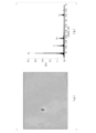
- Evaluation results are shown in Table 1. Moreover, (a) SEM observation result and (b) analysis result (EDX analysis result) of the compound of Invention Example 4 are shown in FIG. 4, and (a) SEM observation result and (b) analysis result of the compound of Invention Example 10 are shown in FIG. FIG. 5 shows (EDX analysis results), and FIG. 6 shows (a) SEM observation results and (b) analysis results (EDX analysis results) of the compound of Inventive Example 19. 4 (b), FIG. 5 (b), and FIG. 6 (b) show the compounds marked with “+” in FIG. 4 (a), FIG. 5 (a), and FIG. 6 (b), respectively. The spectrum of is shown.
- Comparative Example 1 the total amount of inevitable impurities excluding gas components (O, H, C, N, S) exceeded 100 ppm by mass, and the residual resistance ratio (RRR) was relatively low at 106.
- Comparative Example 2 one or more additive elements selected from Ca, Sr, Ba, and rare earth elements (RE) were not added, and the residual resistance ratio (RRR) was 218, which was relatively low. It was.
- Comparative Example 3 the amount of Ca added was 1030 ppm by mass, exceeding the range of the present invention, and cracking occurred during plastic working. For this reason, residual resistance ratio (RRR) and structure
- the residual resistance ratio (RRR) was 250 or more, which was confirmed to be particularly suitable as a superconducting stabilizer.
- FIG. 4 when Ca was added, a compound containing Ca and S was observed.
- FIG. 5 when Sr was added, a compound containing Sr and S was observed.
- FIG. 6 when a rare earth element was added, a rare earth element and S compound was observed. From the above, according to the present invention, it has been confirmed that a superconducting wire provided with a superconducting stabilizer having a sufficiently high residual resistance ratio (RRR) can be provided according to the present invention. It was.
- a superconducting wire that can be used stably is provided with a superconducting stabilizer that can be manufactured at a relatively simple and inexpensive manufacturing process and has a sufficiently high residual resistance ratio (RRR). it can.
Landscapes
- Engineering & Computer Science (AREA)
- Mechanical Engineering (AREA)
- Chemical & Material Sciences (AREA)
- Materials Engineering (AREA)
- Metallurgy (AREA)
- Organic Chemistry (AREA)
- Power Engineering (AREA)
- Manufacturing & Machinery (AREA)
- Superconductors And Manufacturing Methods Therefor (AREA)
- Continuous Casting (AREA)
Abstract
Description
本願は、2015年1月7日に、日本に出願された特願2015-001510号に基づき優先権を主張し、その内容をここに援用する。
この超伝導線は、Nb-Ti合金、Nb3Snなどの超伝導体からなる複数の素線を、超伝導安定化材を介在させて束ねた多芯構造を有している。また、超伝導体と超伝導安定化材とを積層したテープ状の超伝導線も提供されている。
特許文献1においては、特定の元素(Fe,P,Al,As,Sn及びS)の含有量を規定した不純物濃度が非常に低い高純度銅が提案されている。
また、特許文献2においては、酸素濃度の低い高純度銅にZrを微量添加したCu合金が提案されている。
ここで、特許文献1においては、特定の元素(Fe,P,Al,As,Sn及びS)の含有量を0.1ppm未満に限定しているが、これらの元素を0.1ppm未満にまで低減することは容易ではなく、やはり製造プロセスが複雑となるといった問題があった。
また、特許文献2においては、酸素及びZrの含有量を規定しているが、酸素及びZrの含有量を制御することは難しく、高い残留抵抗比(RRR)を有する銅合金を安定して製造することが困難であるといった問題があった。
なお、本発明において希土類元素(RE)とは、La,Ce,Pr,Nd,Pm,Sm,Eu,Gd,Tb,Dy,Ho,Er,Tm,Yb,Lu,Sc,Yである。
また、前記超伝導安定化材においては、ガス成分であるO,H,C,N,Sを除く不可避不純物の濃度の総計が5質量ppm以上100質量ppm以下とされた銅を用いているので、過度に銅の高純度化を図る必要がなく、製造プロセスが簡易となり、製造コストを低減することができる。
不可避不純物の中でも、Fe,Ni,As,Ag,Sn,Sb,Pb,Bi,Pといった特定不純物の元素は、残留抵抗比(RRR)を低下させる作用を有している。そこで、これらの元素の含有量を上述のように規定することで、確実に前記超伝導安定化材の残留抵抗比(RRR)を向上させることが可能となる。
この場合、S,Se,Teの合計含有量(X質量ppm)と、Ca,Sr,Ba,希土類元素から選択される1種又は2種以上の添加元素の合計含有量(Y質量ppm)との比Y/Xが上述の範囲内とされているので、銅中のS,Se,Teを、Ca,Sr,Ba,希土類元素から選択される1種又は2種以上の添加元素との化合物として確実に固定することができ、S,Se,Teによる残留抵抗比(RRR)の低下を確実に抑制することができる。
この場合、銅中に存在するS,Se,Teが、Ca,Sr,Ba,希土類元素から選択される1種又は2種以上の添加元素との化合物によって確実に固定されており、S,Se,Teによる残留抵抗比(RRR)の低下を確実に抑制することができる。
この場合、前記超伝導安定化材の残留抵抗比(RRR)が250以上と比較的高いことから、極低温での抵抗値が十分に低く、超伝導体の超伝導状態が破れた際に電流を十分に迂回させることができ、超伝導体全体に常伝導状態が伝播してしまうことを抑制できる。
この場合、鋳造と圧延とを連続で実施するために、生産効率が高く、長尺の超伝導安定化材を得ることが可能となる。
この構成の超伝導コイルにおいては、上述のように、高い残留抵抗比(RRR)を有する超伝導安定化材を備えた超伝導線を用いているので、安定して使用することが可能となる。
図1に示すように、本実施形態における超伝導線10は、コア部11と、このコア部11の外周側に配置された複数のフィラメント12と、これら複数のフィラメント12の外周側に配置される外殻部13と、を備えている。
ここで、超伝導安定化材20は、図2に示すように、超伝導体からなる素線15の一部において超伝導状態が破れて常伝導領域Aが発生した場合に、超伝導体からなる素線15を流れる電流Iを一時的に迂回させる。
また、本実施形態では、超伝導安定化材20を構成する銅材は、不可避不純物であるFeの含有量が10質量ppm以下、Niの含有量が10質量ppm以下、Asの含有量が5質量ppm以下、Agの含有量が50質量ppm以下、Snの含有量が4質量ppm以下、Sbの含有量が4質量ppm以下、Pbの含有量が6質量ppm以下、Biの含有量が2質量ppm以下、Pの含有量が3質量ppm以下とされている。
さらに、本実施形態である超伝導安定化材20においては、S,Se,Teの合計含有量(X質量ppm)と、Ca,Sr,Ba,希土類元素から選択される1種又は2種以上の添加元素の合計含有量(Y質量ppm)との比Y/Xが、0.5≦Y/X≦100の範囲内とされている。
さらに、本実施形態においては、超伝導安定化材20は、残留抵抗比(RRR)が250以上とされている。
銅に含まれる不可避不純物のうちS,Se,Teは、銅中に固溶することによって残留抵抗比(RRR)を大きく低下させる元素である。このため、残留抵抗比(RRR)を向上させるためには、これらS,Se,Teの影響を排除する必要がある。
ここで、Ca,Sr,Ba,希土類元素から選択される1種又は2種以上の添加元素は、S,Se,Teと反応性が高い元素であることから、S,Se,Teと化合物を生成することによって、これらS,Se,Teが銅中に固溶することを抑制することが可能となる。これにより、超伝導安定化材20の残留抵抗比(RRR)を十分に向上させることができる。
なお、Ca,Sr,Ba,希土類元素から選択される1種又は2種以上の添加元素は、銅中に固溶しにくい元素であり、さらに銅に固溶しても残留抵抗比(RRR)を低下させる作用が小さいことから、S,Se,Teの含有量に対して過剰に添加した場合であっても、超伝導安定化材20の残留抵抗比(RRR)が大きく低下することはない。
なお、S,Se,Teを確実に固定するためには、Ca,Sr,Ba,希土類元素から選択される1種又は2種以上の添加元素の含有量の下限を3.5質量ppm以上とすることが好ましく、4.0質量ppm以上とすることがさらに好ましい。一方、加工性の低下を確実に抑制するためには、Ca,Sr,Ba,希土類元素から選択される1種又は2種以上の添加元素の含有量の上限を300質量ppm以下にすることが好ましく、100質量ppm以下とすることがさらに好ましい。
ガス成分(O,H,C,N,S)を除く不可避不純物については、その濃度を低くすることで残留抵抗比(RRR)が向上することになる。一方、不可避不純物の濃度を必要以上に低減しようとすると、製造プロセスが複雑となって製造コストが大幅に上昇してしまう。そこで、本実施形態では、ガス成分(O,H,C,N,S)を除く不可避不純物の濃度を総計で5質量ppm以上100質量ppm以下の範囲内に設定している。
ガス成分(O,H,C,N,S)を除く不可避不純物の濃度を総計で5質量ppm以上100質量ppm以下の範囲内とするために、原料としては、純度99~99.9999質量%の高純度銅や無酸素銅(C10100,C10200)を用いることができる。ただし、Oが高濃度にあると、Ca,Sr,Ba,希土類元素がOと反応してしまうため、O濃度が20質量ppm以下とすることが好ましく、更に好ましくは10ppm以下である。より好ましくは5質量ppm以下である。
なお、超伝導安定化材20の製造コストの上昇を確実に抑制するためには、不可避不純物の下限を7質量ppm以上とすることが好ましく、10質量ppm以上とすることがさらに好ましい。一方、超伝導安定化材20の残留抵抗比(RRR)を確実に向上させるためには、不可避不純物の上限を90質量ppm以下とすることが好ましく、80質量ppm以下とすることがさらに好ましい。
不可避不純物のうちFe,Ni,As,Ag,Sn,Sb,Pb,Bi,Pといった特定不純物の元素は、超伝導安定化材20の残留抵抗比(RRR)を低下させる作用を有することから、これらの元素の含有量をそれぞれ規定することで、超伝導安定化材20の残留抵抗比(RRR)の低下を確実に抑制することが可能となる。そこで、本実施形態では、Feの含有量を10質量ppm以下、Niの含有量を10質量ppm以下、Asの含有量を5質量ppm以下、Agの含有量を50質量ppm以下、Snの含有量を4質量ppm以下、Sbの含有量を4質量ppm以下、Pbの含有量を6質量ppm以下、Biの含有量を2質量ppm以下、Pの含有量を3質量ppm以下に規定している。
上述のように、Ca,Sr,Ba,希土類元素から選択される1種又は2種以上の添加元素は、S,Se,Teといった元素と化合物を生成することになる。ここで、S,Se,Teの合計含有量(X質量ppm)と添加元素の合計含有量(Y質量ppm)との比Y/Xが0.5未満では、添加元素の含有量が不足し、S,Se,Teといった元素を十分に固定できなくなるおそれがある。
一方、S,Se,Teの合計含有量と添加元素の合計含有量との比Y/Xが100を超えると、S,Se,Teと反応しない余剰の添加元素が多く存在することになり、加工性が低下してしまうおそれがある。
以上のことから、本実施形態では、S,Se,Teの合計含有量と添加元素の合計含有量との比Y/Xを0.5以上100以下の範囲内に規定している。
なお、S,Se,Teといった元素を化合物として確実に固定するためには、S,Se,Teの合計含有量と添加元素の合計含有量との比Y/Xの下限を0.75以上とすることが好ましく、1.0以上とすることがさらに好ましい。また、加工性の低下を確実に抑制するためには、S,Se,Teの合計含有量と添加元素の合計含有量との比Y/Xの上限を75以下とすることが好ましく、50以下とすることがさらに好ましい。ここで、超伝導安定化材20におけるS,Se,Teの合計含有量は0質量ppmを超え25質量ppm以下が好ましいが、これに限定されない。
上述のように、Ca,Sr,Ba,希土類元素から選択される1種又は2種以上の添加元素は、S,Se,Teといった元素と化合物を生成することにより、S,Se,Teといった元素が銅中に固溶することを抑制している。よって、Ca,Sr,Ba,希土類元素から選択される1種又は2種以上の添加元素と、S,Se,Teから選択される1種又は2種以上の元素と、を含む化合物が存在することにより、超伝導安定化材20の残留抵抗比(RRR)を確実に向上させることが可能となる。
なお、本実施形態においては、S,Se,Teといった元素の含有量が十分に少ないことから、上述の化合物(粒径0.1μm以上)の個数密度の上限は0.1個/μm2以下となり、さらに好ましくは0.09個/μm2以下である。より好ましくは0.08個/μm2以下である。
本実施形態である超伝導安定化材20においては、残留抵抗比(RRR)が250以上とされていることから、極低温において、抵抗値が低く電流を良好に迂回させることが可能となる。残留抵抗比(RRR)は、280以上であることが好ましく、300以上であることがさらに好ましい。より好ましくは400以上である。なお、残留抵抗比(RRR)を10000以下とすることが好ましいが、これに限定されない。
なお、連続鋳造圧延法(例えばSCR法)等によって、本実施形態で示した組成の荒引銅線を製造し、これを素材として超伝導安定化材20を製造してもよい。この場合、超伝導安定化材20の生産効率が向上し、製造コストを大幅に低減することが可能となる。ここでいう連続鋳造圧延法とは、例えばベルト・ホイール式連続鋳造機と連続圧延装置とを備えた連続鋳造圧延設備を用いて、銅荒引線を製造し、この銅荒引線を素材として引抜銅線を製造する工程のことである。
また、ガス成分であるO,H,C,N,Sを除く不可避不純物の濃度の総計が5質量ppm以上100質量ppm以下とされた銅を用いているので、過度に銅の高純度化を図る必要がなく、製造プロセスが簡易となり、超伝導安定化材20の製造コストを低減することができる。
特に本実施形態では、粒径0.1μm以上の化合物の個数密度が0.001個/μm2以上とされているので、S,Se,Teを確実に化合物として固定でき、超伝導安定化材20の残留抵抗比(RRR)を十分に向上させることができる。
例えば、超伝導線10を構成するコア部11及び外殻部13についても、本実施形態である超伝導安定化材20と同様の組成の銅材によって構成してもよい。
本実施例では、研究室実験として、純度99.9999質量%の高純度銅及びCa,Sr,Ba,及び希土類元素(RE)の母合金を原料として用いて、表1記載の組成となるように調整した。また、Fe,Ni,As,Ag,Sn,Sb,Pb,Bi,P及びその他の不純物については、純度99.9質量%以上のFe,Ni,As,Ag,Sn,Sb,Pb,Bi,Pと純度99.9質量%の純銅とから各々の元素の母合金を作成し、その母合金を用いて調整した。まず、高純度銅をN2+COの還元性ガス雰囲気中で電気炉を用いて溶解し、その後、各種添加元素及び不純物の母合金を添加して所定濃度に調製し、所定の鋳型に鋳造することにより、直径:70mm×長さ:150mmのインゴットを得た。希土類の母合金の原料には一部ミッシュメタルを用いた。このインゴットから、断面寸法:25mm×25mm角材を切り出し、これに850℃で熱間圧延を施して直径8mmの熱延線材とし、この熱延線材から冷間圧延により直径2.0mmの細線を成形し、これに500℃で1時間保持の歪取り焼鈍を施すことにより、表1に示す評価用線材を製造した。なお、本実施例では、溶解鋳造の過程において不純物元素の混入も認められた。
これらの評価用線材を用いて、以下の項目について評価した。
四端子法にて、293Kでの電気比抵抗(ρ293K)および液体ヘリウム温度(4.2K)での電気比抵抗(ρ4.2K)を測定し、RRR=ρ293K/ρ4.2Kを算出した。
残留抵抗比(RRR)を測定したサンプルを用いて、成分分析を以下のようにして実施した。ガス成分を除く元素について、10質量ppm未満の場合はグロー放電質量分析法、10質量ppm以上の場合は誘導結合プラズマ発光分光分析法を用いた。また、Sの分析には赤外線吸収法を用いた。Oの濃度は全て10質量ppm以下であった。なお、Oの分析は赤外線吸収法を用いた。
Ca,Sr,Ba,希土類元素から選択される1種又は2種以上の添加元素と、S,Se,Teのうち1種又は2種以上と、を含む化合物粒子の有無を確認するために、SEM(走査型電子顕微鏡)を用いて粒子観察し、この化合物粒子のEDX分析(エネルギー分散型X線分光法)を実施した。
また、化合物の個数密度(個/μm2)を評価するために、化合物の分散状態が特異ではない領域について、10000倍(観察視野:2×108nm2)で観察し、10視野(観察視野合計:2×109nm2)の撮影を行った。化合物の粒径については、化合物の長径(途中で粒界に接しない条件で粒内に最も長く引ける直線の長さ)と短径(長径と直角に交わる方向で、途中で粒界に接しない条件で最も長く引ける直線の長さ)の平均値とした。そして、粒径0.1μm以上の化合物の個数密度(個/μm2)を求めた。

比較例2は、Ca,Sr,Ba,希土類元素(RE)から選択される1種又は2種以上の添加元素を添加しなかったものであり、残留抵抗比(RRR)が218と比較的低かった。
比較例3は、Caの添加量が1030質量ppmと本発明の範囲を超えており、塑性加工中に割れが生じた。このため、残留抵抗比(RRR)及び組織観察を実施しなかった。
また、図4に示すように、Caを添加した場合には、CaとSを含む化合物が観察された。
さらに、図5に示すように、Srを添加した場合には、SrとSを含む化合物が観察された。
さらに、図6に示すように、希土類元素を添加した場合には、希土類元素とSの化合物が観察された。
以上のことから、本発明によれば、製造プロセスが比較的簡単で廉価で製造でき、残留抵抗比(RRR)が十分に高い超伝導安定化材を備えた超伝導線を提供できることが確認された。
20、120 超伝導安定化材
Claims (7)
- 超伝導体からなる素線と、この素線に接触して配置される超伝導安定化材と、を備えた超伝導線であって、
前記超伝導安定化材は、Ca,Sr,Ba,希土類元素から選択される1種又は2種以上の添加元素を合計で3質量ppm以上400質量ppm以下の範囲内で含有し、残部がCu及び不可避不純物とされるとともに、ガス成分であるO,H,C,N,Sを除く前記不可避不純物の濃度の総計が5質量ppm以上100質量ppm以下とされた銅材からなることを特徴とする超伝導線。 - 前記超伝導安定化材は、前記不可避不純物であるFeの含有量が10質量ppm以下、Niの含有量が10質量ppm以下、Asの含有量が5質量ppm以下、Agの含有量が50質量ppm以下、Snの含有量が4質量ppm以下、Sbの含有量が4質量ppm以下、Pbの含有量が6質量ppm以下、Biの含有量が2質量ppm以下、Pの含有量が3質量ppm以下とされた前記銅材からなることを特徴とする請求項1に記載の超伝導線。
- 前記超伝導安定化材は、S,Se,Teの合計含有量(X質量ppm)と、Ca,Sr,Ba,希土類元素から選択される1種又は2種以上の添加元素の合計含有量(Y質量ppm)との比Y/Xが、0.5≦Y/X≦100の範囲内とされた前記銅材からなることを特徴とする請求項1又は請求項2に記載の超伝導線。
- 前記超伝導安定化材は、Ca,Sr,Ba,希土類元素から選択される1種又は2種以上の添加元素とS,Se,Teから選択される1種又は2種以上の元素とを含む化合物が存在する前記銅材からなることを特徴とする請求項1から請求項3のいずれか一項に記載の超伝導線。
- 前記超伝導安定化材は、残留抵抗比(RRR)が250以上であることを特徴とする請求項1から請求項4のいずれか一項に記載の超伝導線。
- 前記超伝導安定化材は、連続鋳造圧延法で製造されていることを特徴とする請求項1から請求項5のいずれか一項に記載の超伝導線。
- 請求項1から請求項6のいずれか一項に記載の超伝導線が巻枠の周面に巻回されてなる巻線部を備えた構造を有することを特徴とする超伝導コイル。
Priority Applications (5)
| Application Number | Priority Date | Filing Date | Title |
|---|---|---|---|
| EP15877032.1A EP3243916B1 (en) | 2015-01-07 | 2015-12-22 | Superconducting wire and superconducting coil |
| CN201580066340.7A CN107002179B (zh) | 2015-01-07 | 2015-12-22 | 超导线及超导线圈 |
| US15/540,928 US10964454B2 (en) | 2015-01-07 | 2015-12-22 | Superconducting wire and superconducting coil |
| KR1020177015244A KR102450307B1 (ko) | 2015-01-07 | 2015-12-22 | 초전도선 및 초전도 코일 |
| US17/069,479 US20210225560A1 (en) | 2015-01-07 | 2020-10-13 | Superconducting wire and superconducting coil |
Applications Claiming Priority (2)
| Application Number | Priority Date | Filing Date | Title |
|---|---|---|---|
| JP2015-001510 | 2015-01-07 | ||
| JP2015001510A JP6056877B2 (ja) | 2015-01-07 | 2015-01-07 | 超伝導線、及び、超伝導コイル |
Related Child Applications (2)
| Application Number | Title | Priority Date | Filing Date |
|---|---|---|---|
| US15/540,928 A-371-Of-International US10964454B2 (en) | 2015-01-07 | 2015-12-22 | Superconducting wire and superconducting coil |
| US17/069,479 Continuation US20210225560A1 (en) | 2015-01-07 | 2020-10-13 | Superconducting wire and superconducting coil |
Publications (1)
| Publication Number | Publication Date |
|---|---|
| WO2016111159A1 true WO2016111159A1 (ja) | 2016-07-14 |
Family
ID=56355859
Family Applications (1)
| Application Number | Title | Priority Date | Filing Date |
|---|---|---|---|
| PCT/JP2015/085765 WO2016111159A1 (ja) | 2015-01-07 | 2015-12-22 | 超伝導線、及び、超伝導コイル |
Country Status (7)
| Country | Link |
|---|---|
| US (2) | US10964454B2 (ja) |
| EP (1) | EP3243916B1 (ja) |
| JP (1) | JP6056877B2 (ja) |
| KR (1) | KR102450307B1 (ja) |
| CN (2) | CN107002179B (ja) |
| TW (1) | TWI596622B (ja) |
| WO (1) | WO2016111159A1 (ja) |
Cited By (1)
| Publication number | Priority date | Publication date | Assignee | Title |
|---|---|---|---|---|
| CN111279002A (zh) * | 2017-10-30 | 2020-06-12 | 三菱综合材料株式会社 | 超导稳定化材料、超导线及超导线圈 |
Families Citing this family (9)
| Publication number | Priority date | Publication date | Assignee | Title |
|---|---|---|---|---|
| JP6056876B2 (ja) * | 2015-01-07 | 2017-01-11 | 三菱マテリアル株式会社 | 超伝導安定化材 |
| JP6056877B2 (ja) | 2015-01-07 | 2017-01-11 | 三菱マテリアル株式会社 | 超伝導線、及び、超伝導コイル |
| JP6299802B2 (ja) | 2016-04-06 | 2018-03-28 | 三菱マテリアル株式会社 | 超伝導安定化材、超伝導線及び超伝導コイル |
| JP6299803B2 (ja) | 2016-04-06 | 2018-03-28 | 三菱マテリアル株式会社 | 超伝導線、及び、超伝導コイル |
| JP7039924B2 (ja) | 2017-10-20 | 2022-03-23 | 株式会社ノーリツ | 熱動弁及び温水暖房装置 |
| CN109961899B (zh) * | 2017-12-25 | 2020-12-01 | 西部超导材料科技股份有限公司 | 一种在线热拉制备青铜法Nb3Sn超导线材的方法 |
| JP7380550B2 (ja) * | 2018-12-13 | 2023-11-15 | 三菱マテリアル株式会社 | 純銅板 |
| WO2020203071A1 (ja) * | 2019-03-29 | 2020-10-08 | 三菱マテリアル株式会社 | 銅材及び放熱部材 |
| CN112322924B (zh) * | 2020-10-16 | 2022-05-20 | 中南大学 | 一种无氧铜、制备方法及应用 |
Citations (3)
| Publication number | Priority date | Publication date | Assignee | Title |
|---|---|---|---|---|
| JPH04224662A (ja) * | 1990-12-26 | 1992-08-13 | Hitachi Cable Ltd | 高残留抵抗比銅材の製造方法 |
| WO2005073434A1 (ja) * | 2004-01-29 | 2005-08-11 | Nippon Mining & Metals Co., Ltd. | 超高純度銅及びその製造方法 |
| WO2006134724A1 (ja) * | 2005-06-15 | 2006-12-21 | Nippon Mining & Metals Co., Ltd. | 超高純度銅及びその製造方法並びに超高純度銅からなるボンディングワイヤ |
Family Cites Families (28)
| Publication number | Priority date | Publication date | Assignee | Title |
|---|---|---|---|---|
| JPS5474698A (en) | 1977-11-28 | 1979-06-14 | Univ Tohoku | Superconductive thin band and method of fabricating same |
| JPS6058291B2 (ja) | 1978-01-20 | 1985-12-19 | 住友電気工業株式会社 | 銅合金軟導体およびその製造法 |
| US4233067A (en) | 1978-01-19 | 1980-11-11 | Sumitomo Electric Industries, Ltd. | Soft copper alloy conductors |
| JPS6062009A (ja) | 1983-09-14 | 1985-04-10 | 日立電線株式会社 | Ag入り無酸素銅により安定化された複合超電導体 |
| US4568567A (en) * | 1984-10-09 | 1986-02-04 | Rca Corporation | Method of removing trace quantities of alkali metal impurities from a bialkali-antimonide photoemissive cathode |
| JPS63140052A (ja) * | 1986-12-01 | 1988-06-11 | Hitachi Cable Ltd | 低温軟化性を有する無酸素銅ベ−ス希薄合金及びその用途 |
| JPS63235440A (ja) | 1987-03-23 | 1988-09-30 | Furukawa Electric Co Ltd:The | 銅細線及びその製造方法 |
| JPH01143744A (ja) | 1987-11-30 | 1989-06-06 | Aichi Steel Works Ltd | 酸化物超電導細線の製造方法 |
| JPH02145737A (ja) * | 1988-11-24 | 1990-06-05 | Dowa Mining Co Ltd | 高強度高導電性銅基合金 |
| US5043025A (en) * | 1990-06-12 | 1991-08-27 | Iowa State University Research Foundation, Inc. | High strength-high conductivity Cu--Fe composites produced by powder compaction/mechanical reduction |
| JP3047540B2 (ja) | 1991-07-23 | 2000-05-29 | 三菱マテリアル株式会社 | 高い残留抵抗比を有する超電導安定化材用高純度Cu合金 |
| CN1080779A (zh) * | 1993-05-05 | 1994-01-12 | 北京有色金属研究总院 | 极细多芯低温超导线带用的铜合金 |
| US20040266628A1 (en) * | 2003-06-27 | 2004-12-30 | Superpower, Inc. | Novel superconducting articles, and methods for forming and using same |
| JP2005056754A (ja) | 2003-08-06 | 2005-03-03 | Sumitomo Electric Ind Ltd | 超電導線材およびその製造方法 |
| JP2009507358A (ja) | 2005-07-29 | 2009-02-19 | アメリカン・スーパーコンダクター・コーポレーション | 高温超電導ワイヤ及びコイル |
| WO2007136406A2 (en) | 2005-11-08 | 2007-11-29 | Supramagnetics, Inc. | Composite conductors with improved structural and electrical properties |
| JP4538813B2 (ja) * | 2006-05-29 | 2010-09-08 | Dowaホールディングス株式会社 | 銅基合金材を用いたコネクタ及び充電用ソケット |
| JP5717236B2 (ja) * | 2010-05-12 | 2015-05-13 | 三菱マテリアル株式会社 | 粒子加速器 |
| JP5589753B2 (ja) | 2010-10-20 | 2014-09-17 | 日立金属株式会社 | 溶接部材、及びその製造方法 |
| CN103534370B (zh) | 2011-08-29 | 2015-11-25 | 古河电气工业株式会社 | 铜合金材料及其制造方法 |
| SG190482A1 (en) | 2011-12-01 | 2013-06-28 | Heraeus Materials Tech Gmbh | Doped 4n copper wire for bonding in microelectronics device |
| DE102012205843A1 (de) | 2012-04-11 | 2013-10-17 | Bruker Eas Gmbh | NbTi-Supraleiter mit reduziertem Gewicht |
| JP6101491B2 (ja) | 2012-11-30 | 2017-03-22 | 株式会社フジクラ | 酸化物超電導線材及びその製造方法 |
| JP5752736B2 (ja) | 2013-04-08 | 2015-07-22 | 三菱マテリアル株式会社 | スパッタリング用ターゲット |
| CN103985479B (zh) | 2014-04-28 | 2018-03-30 | 赵遵成 | 一种高温超导涂层导体带材的制备方法 |
| JP6056877B2 (ja) | 2015-01-07 | 2017-01-11 | 三菱マテリアル株式会社 | 超伝導線、及び、超伝導コイル |
| JP6056876B2 (ja) * | 2015-01-07 | 2017-01-11 | 三菱マテリアル株式会社 | 超伝導安定化材 |
| JP6299803B2 (ja) | 2016-04-06 | 2018-03-28 | 三菱マテリアル株式会社 | 超伝導線、及び、超伝導コイル |
-
2015
- 2015-01-07 JP JP2015001510A patent/JP6056877B2/ja active Active
- 2015-12-22 WO PCT/JP2015/085765 patent/WO2016111159A1/ja active Application Filing
- 2015-12-22 EP EP15877032.1A patent/EP3243916B1/en active Active
- 2015-12-22 CN CN201580066340.7A patent/CN107002179B/zh active Active
- 2015-12-22 KR KR1020177015244A patent/KR102450307B1/ko active IP Right Grant
- 2015-12-22 US US15/540,928 patent/US10964454B2/en active Active
- 2015-12-22 CN CN201810575450.1A patent/CN108766661B/zh active Active
- 2015-12-28 TW TW104144089A patent/TWI596622B/zh active
-
2020
- 2020-10-13 US US17/069,479 patent/US20210225560A1/en not_active Abandoned
Patent Citations (3)
| Publication number | Priority date | Publication date | Assignee | Title |
|---|---|---|---|---|
| JPH04224662A (ja) * | 1990-12-26 | 1992-08-13 | Hitachi Cable Ltd | 高残留抵抗比銅材の製造方法 |
| WO2005073434A1 (ja) * | 2004-01-29 | 2005-08-11 | Nippon Mining & Metals Co., Ltd. | 超高純度銅及びその製造方法 |
| WO2006134724A1 (ja) * | 2005-06-15 | 2006-12-21 | Nippon Mining & Metals Co., Ltd. | 超高純度銅及びその製造方法並びに超高純度銅からなるボンディングワイヤ |
Non-Patent Citations (2)
| Title |
|---|
| See also references of EP3243916A4 * |
| VOROBIEVA, A. ET AL.: "The experimental investigation of copper for superconductors", PHYSICA C, vol. 354, 2001, pages 371 - 374, XP027412101, ISSN: 0921-4534 * |
Cited By (3)
| Publication number | Priority date | Publication date | Assignee | Title |
|---|---|---|---|---|
| CN111279002A (zh) * | 2017-10-30 | 2020-06-12 | 三菱综合材料株式会社 | 超导稳定化材料、超导线及超导线圈 |
| EP3705589A4 (en) * | 2017-10-30 | 2021-08-11 | Mitsubishi Materials Corporation | SUPRACONDUCTIVITY STABILIZATION MATERIAL, SUPPRACONDUCTOR WIRE AND SUPPRACONDUCTOR COIL |
| US11613794B2 (en) | 2017-10-30 | 2023-03-28 | Mitsubishi Materials Corporation | Superconductivity stabilizing material, superconducting wire and superconducting coil |
Also Published As
| Publication number | Publication date |
|---|---|
| KR20170102224A (ko) | 2017-09-08 |
| US20210225560A1 (en) | 2021-07-22 |
| CN108766661B (zh) | 2020-09-25 |
| CN107002179B (zh) | 2018-11-16 |
| EP3243916B1 (en) | 2019-03-27 |
| EP3243916A4 (en) | 2018-05-30 |
| JP6056877B2 (ja) | 2017-01-11 |
| TWI596622B (zh) | 2017-08-21 |
| US10964454B2 (en) | 2021-03-30 |
| CN107002179A (zh) | 2017-08-01 |
| TW201643900A (zh) | 2016-12-16 |
| CN108766661A (zh) | 2018-11-06 |
| JP2016125115A (ja) | 2016-07-11 |
| US20180005731A1 (en) | 2018-01-04 |
| KR102450307B1 (ko) | 2022-09-30 |
| EP3243916A1 (en) | 2017-11-15 |
Similar Documents
| Publication | Publication Date | Title |
|---|---|---|
| JP6056877B2 (ja) | 超伝導線、及び、超伝導コイル | |
| JP6299803B2 (ja) | 超伝導線、及び、超伝導コイル | |
| WO2016111173A1 (ja) | 超伝導安定化材、超伝導線及び超伝導コイル | |
| JP6299804B2 (ja) | 超伝導安定化材、超伝導線及び超伝導コイル | |
| JP6668899B2 (ja) | 超伝導安定化材、超伝導線及び超伝導コイル | |
| JP6057007B2 (ja) | 超伝導安定化材、超伝導線及び超伝導コイル | |
| JP6299802B2 (ja) | 超伝導安定化材、超伝導線及び超伝導コイル | |
| JP6057008B2 (ja) | 超伝導線、及び、超伝導コイル | |
| JPWO2019088080A1 (ja) | 超伝導安定化材、超伝導線及び超伝導コイル |
Legal Events
| Date | Code | Title | Description |
|---|---|---|---|
| 121 | Ep: the epo has been informed by wipo that ep was designated in this application |
Ref document number: 15877032 Country of ref document: EP Kind code of ref document: A1 |
|
| ENP | Entry into the national phase |
Ref document number: 20177015244 Country of ref document: KR Kind code of ref document: A |
|
| WWE | Wipo information: entry into national phase |
Ref document number: 15540928 Country of ref document: US |
|
| REEP | Request for entry into the european phase |
Ref document number: 2015877032 Country of ref document: EP |
|
| NENP | Non-entry into the national phase |
Ref country code: DE |