WO2016093338A1 - 蓄電素子 - Google Patents
蓄電素子 Download PDFInfo
- Publication number
- WO2016093338A1 WO2016093338A1 PCT/JP2015/084758 JP2015084758W WO2016093338A1 WO 2016093338 A1 WO2016093338 A1 WO 2016093338A1 JP 2015084758 W JP2015084758 W JP 2015084758W WO 2016093338 A1 WO2016093338 A1 WO 2016093338A1
- Authority
- WO
- WIPO (PCT)
- Prior art keywords
- portions
- current collecting
- bent
- electrode
- current
- Prior art date
Links
Images


Classifications
-
- H—ELECTRICITY
- H01—ELECTRIC ELEMENTS
- H01G—CAPACITORS; CAPACITORS, RECTIFIERS, DETECTORS, SWITCHING DEVICES OR LIGHT-SENSITIVE DEVICES, OF THE ELECTROLYTIC TYPE
- H01G11/00—Hybrid capacitors, i.e. capacitors having different positive and negative electrodes; Electric double-layer [EDL] capacitors; Processes for the manufacture thereof or of parts thereof
- H01G11/66—Current collectors
- H01G11/72—Current collectors specially adapted for integration in multiple or stacked hybrid or EDL capacitors
-
- H—ELECTRICITY
- H01—ELECTRIC ELEMENTS
- H01G—CAPACITORS; CAPACITORS, RECTIFIERS, DETECTORS, SWITCHING DEVICES OR LIGHT-SENSITIVE DEVICES, OF THE ELECTROLYTIC TYPE
- H01G11/00—Hybrid capacitors, i.e. capacitors having different positive and negative electrodes; Electric double-layer [EDL] capacitors; Processes for the manufacture thereof or of parts thereof
- H01G11/74—Terminals, e.g. extensions of current collectors
- H01G11/76—Terminals, e.g. extensions of current collectors specially adapted for integration in multiple or stacked hybrid or EDL capacitors
-
- H—ELECTRICITY
- H01—ELECTRIC ELEMENTS
- H01G—CAPACITORS; CAPACITORS, RECTIFIERS, DETECTORS, SWITCHING DEVICES OR LIGHT-SENSITIVE DEVICES, OF THE ELECTROLYTIC TYPE
- H01G11/00—Hybrid capacitors, i.e. capacitors having different positive and negative electrodes; Electric double-layer [EDL] capacitors; Processes for the manufacture thereof or of parts thereof
- H01G11/78—Cases; Housings; Encapsulations; Mountings
- H01G11/82—Fixing or assembling a capacitive element in a housing, e.g. mounting electrodes, current collectors or terminals in containers or encapsulations
-
- H—ELECTRICITY
- H01—ELECTRIC ELEMENTS
- H01M—PROCESSES OR MEANS, e.g. BATTERIES, FOR THE DIRECT CONVERSION OF CHEMICAL ENERGY INTO ELECTRICAL ENERGY
- H01M50/00—Constructional details or processes of manufacture of the non-active parts of electrochemical cells other than fuel cells, e.g. hybrid cells
- H01M50/10—Primary casings, jackets or wrappings of a single cell or a single battery
- H01M50/102—Primary casings, jackets or wrappings of a single cell or a single battery characterised by their shape or physical structure
- H01M50/103—Primary casings, jackets or wrappings of a single cell or a single battery characterised by their shape or physical structure prismatic or rectangular
-
- H—ELECTRICITY
- H01—ELECTRIC ELEMENTS
- H01M—PROCESSES OR MEANS, e.g. BATTERIES, FOR THE DIRECT CONVERSION OF CHEMICAL ENERGY INTO ELECTRICAL ENERGY
- H01M50/00—Constructional details or processes of manufacture of the non-active parts of electrochemical cells other than fuel cells, e.g. hybrid cells
- H01M50/10—Primary casings, jackets or wrappings of a single cell or a single battery
- H01M50/172—Arrangements of electric connectors penetrating the casing
- H01M50/174—Arrangements of electric connectors penetrating the casing adapted for the shape of the cells
- H01M50/176—Arrangements of electric connectors penetrating the casing adapted for the shape of the cells for prismatic or rectangular cells
-
- H—ELECTRICITY
- H01—ELECTRIC ELEMENTS
- H01M—PROCESSES OR MEANS, e.g. BATTERIES, FOR THE DIRECT CONVERSION OF CHEMICAL ENERGY INTO ELECTRICAL ENERGY
- H01M50/00—Constructional details or processes of manufacture of the non-active parts of electrochemical cells other than fuel cells, e.g. hybrid cells
- H01M50/40—Separators; Membranes; Diaphragms; Spacing elements inside cells
- H01M50/46—Separators, membranes or diaphragms characterised by their combination with electrodes
-
- H—ELECTRICITY
- H01—ELECTRIC ELEMENTS
- H01M—PROCESSES OR MEANS, e.g. BATTERIES, FOR THE DIRECT CONVERSION OF CHEMICAL ENERGY INTO ELECTRICAL ENERGY
- H01M50/00—Constructional details or processes of manufacture of the non-active parts of electrochemical cells other than fuel cells, e.g. hybrid cells
- H01M50/50—Current conducting connections for cells or batteries
- H01M50/531—Electrode connections inside a battery casing
- H01M50/536—Electrode connections inside a battery casing characterised by the method of fixing the leads to the electrodes, e.g. by welding
-
- H—ELECTRICITY
- H01—ELECTRIC ELEMENTS
- H01M—PROCESSES OR MEANS, e.g. BATTERIES, FOR THE DIRECT CONVERSION OF CHEMICAL ENERGY INTO ELECTRICAL ENERGY
- H01M50/00—Constructional details or processes of manufacture of the non-active parts of electrochemical cells other than fuel cells, e.g. hybrid cells
- H01M50/50—Current conducting connections for cells or batteries
- H01M50/543—Terminals
- H01M50/547—Terminals characterised by the disposition of the terminals on the cells
- H01M50/55—Terminals characterised by the disposition of the terminals on the cells on the same side of the cell
-
- H—ELECTRICITY
- H01—ELECTRIC ELEMENTS
- H01M—PROCESSES OR MEANS, e.g. BATTERIES, FOR THE DIRECT CONVERSION OF CHEMICAL ENERGY INTO ELECTRICAL ENERGY
- H01M50/00—Constructional details or processes of manufacture of the non-active parts of electrochemical cells other than fuel cells, e.g. hybrid cells
- H01M50/50—Current conducting connections for cells or batteries
- H01M50/543—Terminals
- H01M50/552—Terminals characterised by their shape
- H01M50/553—Terminals adapted for prismatic, pouch or rectangular cells
-
- H—ELECTRICITY
- H01—ELECTRIC ELEMENTS
- H01M—PROCESSES OR MEANS, e.g. BATTERIES, FOR THE DIRECT CONVERSION OF CHEMICAL ENERGY INTO ELECTRICAL ENERGY
- H01M50/00—Constructional details or processes of manufacture of the non-active parts of electrochemical cells other than fuel cells, e.g. hybrid cells
- H01M50/50—Current conducting connections for cells or batteries
- H01M50/543—Terminals
- H01M50/562—Terminals characterised by the material
-
- H—ELECTRICITY
- H01—ELECTRIC ELEMENTS
- H01M—PROCESSES OR MEANS, e.g. BATTERIES, FOR THE DIRECT CONVERSION OF CHEMICAL ENERGY INTO ELECTRICAL ENERGY
- H01M50/00—Constructional details or processes of manufacture of the non-active parts of electrochemical cells other than fuel cells, e.g. hybrid cells
- H01M50/50—Current conducting connections for cells or batteries
- H01M50/543—Terminals
- H01M50/564—Terminals characterised by their manufacturing process
- H01M50/567—Terminals characterised by their manufacturing process by fixing means, e.g. screws, rivets or bolts
-
- Y—GENERAL TAGGING OF NEW TECHNOLOGICAL DEVELOPMENTS; GENERAL TAGGING OF CROSS-SECTIONAL TECHNOLOGIES SPANNING OVER SEVERAL SECTIONS OF THE IPC; TECHNICAL SUBJECTS COVERED BY FORMER USPC CROSS-REFERENCE ART COLLECTIONS [XRACs] AND DIGESTS
- Y02—TECHNOLOGIES OR APPLICATIONS FOR MITIGATION OR ADAPTATION AGAINST CLIMATE CHANGE
- Y02E—REDUCTION OF GREENHOUSE GAS [GHG] EMISSIONS, RELATED TO ENERGY GENERATION, TRANSMISSION OR DISTRIBUTION
- Y02E60/00—Enabling technologies; Technologies with a potential or indirect contribution to GHG emissions mitigation
- Y02E60/10—Energy storage using batteries
-
- Y—GENERAL TAGGING OF NEW TECHNOLOGICAL DEVELOPMENTS; GENERAL TAGGING OF CROSS-SECTIONAL TECHNOLOGIES SPANNING OVER SEVERAL SECTIONS OF THE IPC; TECHNICAL SUBJECTS COVERED BY FORMER USPC CROSS-REFERENCE ART COLLECTIONS [XRACs] AND DIGESTS
- Y02—TECHNOLOGIES OR APPLICATIONS FOR MITIGATION OR ADAPTATION AGAINST CLIMATE CHANGE
- Y02E—REDUCTION OF GREENHOUSE GAS [GHG] EMISSIONS, RELATED TO ENERGY GENERATION, TRANSMISSION OR DISTRIBUTION
- Y02E60/00—Enabling technologies; Technologies with a potential or indirect contribution to GHG emissions mitigation
- Y02E60/13—Energy storage using capacitors
-
- Y—GENERAL TAGGING OF NEW TECHNOLOGICAL DEVELOPMENTS; GENERAL TAGGING OF CROSS-SECTIONAL TECHNOLOGIES SPANNING OVER SEVERAL SECTIONS OF THE IPC; TECHNICAL SUBJECTS COVERED BY FORMER USPC CROSS-REFERENCE ART COLLECTIONS [XRACs] AND DIGESTS
- Y02—TECHNOLOGIES OR APPLICATIONS FOR MITIGATION OR ADAPTATION AGAINST CLIMATE CHANGE
- Y02P—CLIMATE CHANGE MITIGATION TECHNOLOGIES IN THE PRODUCTION OR PROCESSING OF GOODS
- Y02P70/00—Climate change mitigation technologies in the production process for final industrial or consumer products
- Y02P70/50—Manufacturing or production processes characterised by the final manufactured product
Definitions
- the present invention relates to a storage element including a non-electrolyte secondary battery such as a lithium ion secondary battery.
- Patent Document 1 discloses a power storage element including an electrode body wound in an oval shape in a plan view with a separator interposed between a positive electrode sheet and a negative electrode sheet.
- the electrode body is provided with a positive electrode current collecting tab and a negative electrode current collecting tab with a space between the first straight line portions on one side of the pair of opposed straight line portions.
- a spacer is disposed above the current collecting tab, and the current collecting tab is electrically connected to the current collector above the spacer.
- Patent Document 1 requires a large space for arranging the current collector above the first straight portion where the current collector tab of the electrode body is protruded. For this reason, when manufacturing a storage element having the same height, it is necessary to make the electrode body small, so that the capacity of the storage element is reduced.
- An object of the present invention is to increase the capacity of a power storage element.
- the present invention provides a positive electrode current collecting tab composed of positive electrode sheets and negative electrode sheets alternately stacked with separators interposed therebetween, and a plurality of protrusions protruding from a first portion on one side in the stacking direction of each electrode sheet,
- An electrode body housed in a case, a positive electrode external terminal and a negative electrode external terminal disposed in the case, and disposed between the electrode body and the case. It is electrically connected to the terminals and electrically connected to the current collecting tabs arranged in the stacking direction of the electrode sheets on the second portion side on the other side in the stacking direction of the electrode sheets.
- a power storage device comprising a positive electrode current collector and a negative electrode current collector is provided.
- the current collecting tab protrudes from the first portion side of the electrode body, and the connecting portion between the current collecting tab and the current collector is located on the second portion side where the current collecting tab does not protrude. Therefore, it is possible to reduce the height at the end of the electrode body, and to reduce the distance between the electrode body and the case. For this reason, in the case of manufacturing a power storage element having the same height, the electrode body can be enlarged, so that the capacity can be increased.
- the electricity storage device it is possible to reduce the height of the end of the electrode body and increase the capacity of the electricity storage device.
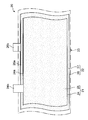
- FIG. 1 is a longitudinal sectional view of a non-electrolyte secondary battery according to a first embodiment of the present invention.
- the disassembled perspective view of the non-electrolyte secondary battery of FIG. The perspective view of an electrode body.
- the enlarged view of the part VI of FIG. The perspective view of an electrode body and a collector.
- FIG. 2 is a partially broken exploded side view of the non-electrolyte secondary battery of FIG. 1.
- Sectional drawing which shows the state which assembled
- Sectional drawing which shows the assembly
- Sectional drawing which shows the other assembly
- the partial cross section figure of the non-electrolyte secondary battery which concerns on 2nd Embodiment.
- First embodiment 1 and 2 show a lithium ion secondary battery (hereinafter simply referred to as a battery) 1 according to a first embodiment of the present invention.
- the battery 1 includes an outer package 10, an electrode body 20, an insulating sheet 30, a bottom spacer 40, positive and negative external terminals 50A and 50B, positive and negative current collectors 60A and 60B, an upper packing. 70A, 70B, lower packings 80A, 80B, and an upper spacer 90 are provided.
- the exterior body (case) 10 includes a case main body 11 and a lid 12 that closes an opening 11 a of the case main body 11.
- the case body 11 and the lid 12 are made of aluminum or an aluminum alloy.
- the case body 11 has a rectangular plate-like bottom wall portion 11b, a pair of long side wall portions 11c, 11c rising from the long side of the bottom wall portion 11b, and a pair of short side wall portions 11d, 11d rising from the short side of the bottom wall portion 11b.
- the lid 12 has a generally rectangular plate shape. Upper ends of the long side wall portion 11 c and the short side wall portion 11 d define an opening 11 a of the case body 11.
- An electrode body 20 is accommodated in the case body 11 filled with the electrolytic solution.
- the electrode body 20 is covered with an insulating sheet 30.
- a bottom spacer 40 is interposed between the electrode body 20 and the bottom wall portion 11 b of the case body 11.
- Lower packings 80 ⁇ / b> A and 80 ⁇ / b> B and an upper spacer 90 are also accommodated in the case body 11.
- the electrode body 20 includes a positive electrode sheet 21, a negative electrode sheet 22, and two separators 23 made of a microporous resin sheet, each of which is a long strip having a constant width. , 23 are overlapped and wound in an oval shape with a generally high flatness.
- One of the two separators 23 and 23 is interposed between one layer of the positive electrode sheet 21 and one layer of the negative electrode sheet 22 adjacent thereto.
- the winding axis (winding axis) of the positive electrode sheet 21, the negative electrode sheet 22, and the two separators 23, 23 is conceptually indicated by reference numeral A in FIG.
- the electrode body 20 is accommodated in the case main body 11 in such a posture that the winding axis A extends in a direction in which the bottom wall portion 11b of the case main body 11 and the opening 11a face each other (vertical direction in FIG. 1).
- the ends 20a and 20b of the electrode body 20 viewed from the direction in which the winding axis A extends connect a pair of linear portions 20c and 20d facing each other and the linear portions 20c and 20d.
- it has a pair of curved parts 20e and 20e which mutually oppose.
- the positive electrode sheet 21 includes a strip-like positive electrode metal foil 24 and a positive electrode active material layer 25 formed on both surfaces of the positive electrode metal foil 24.
- the positive electrode active material layer 25 is provided up to the side edge of the positive electrode metal foil 24 at one end (the lower side in FIGS. 3 and 4) in the width direction of the positive electrode sheet 21. At the other end in the width direction of the positive electrode sheet 21 (upper side in FIGS. 3 and 4), an uncoated portion 24a in which the positive electrode metal foil 24 is exposed is provided without providing the positive electrode active material layer 25. ing.
- the negative electrode sheet 22 includes a strip-shaped negative electrode metal foil 26 and a negative electrode active material layer 27 formed on both surfaces of the negative electrode metal foil 26. At one end in the width direction of the negative electrode sheet 22 (lower side in FIGS. 3 and 4), the negative electrode active material layer 27 is provided up to the side edge of the negative electrode metal foil 26. At the other end in the width direction of the negative electrode sheet 22 (upper side in FIGS. 3 and 4), an uncoated portion 26a in which the negative electrode metal foil 26 is exposed without providing the negative electrode active material layer 27 is provided. ing.
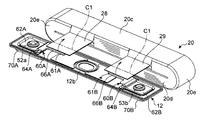
- the positive electrode metal foil 24 is provided with a plurality of protrusions 24b protruding outward in the width direction from the uncoated part 24a with an interval in the longitudinal direction.
- a tab-shaped portion in which a plurality of protrusions 24b are overlapped with each other and protrude from the electrode body 20 28.
- the negative electrode metal foil 26 is also provided with a plurality of protrusions 26b similar to the protrusions 24b of the positive electrode metal foil 24.
- the negative electrode current collector protruding from the electrode body 20 by overlapping these protrusions 26b. Tabs 29 are formed.
- the positive electrode current collecting tab 28 and the negative electrode current collecting tab 29 protrude from one end portion 20a (the upper end portion in FIG. 3) of the electrode body 20. Moreover, one side (front side in FIG. 3) of the pair of linear portions 20c and 20d with respect to the center line B in the longitudinal direction when the end portion 20a of the electrode body 20 is viewed from the direction in which the winding axis A extends.
- a positive current collecting tab 28 and a negative current collecting tab 29 protrude from the first straight portion 20c.
- a positive external terminal 50A is disposed on one end side (left side in FIG. 1) of the lid 12, and a negative external terminal 50B is disposed on the other end side (right side in FIG. 1).
- the external terminals 50 ⁇ / b> A and 50 ⁇ / b> B include plate-like portions 51 ⁇ / b> A and 51 ⁇ / b> B disposed on the outer side surface (upper side surface) 12 a of the lid 12.
- a connecting member such as a bus bar is welded to the plate-like portions 51A and 51B and connected to an external circuit.
- the positive external terminal 50A includes a plate-like portion 51A disposed on the outer surface 12a of the lid 12, and a cylindrical shape protruding downward from the lower surface of the plate-like portion 51A.
- the shaft part 52 is provided.
- the plate-like portion 51A and the shaft portion 52 are integrally formed.
- the shaft portion 52 penetrates the lid 12 and projects into the case main body 11.
- a diameter-increased portion 52a is provided at the lower end of the shaft portion 52 of the positive external terminal 50A, whereby the positive external terminal 50A is caulked and fixed to the lid 12.
- an insulating resin upper packing 70A, a lid 12, an insulating resin lower packing 80A, and a positive current collector 60A are provided between the plate-like portion 51A and the enlarged diameter portion 52a of the external terminal 50A.
- An upper packing 70A is interposed between the outer surface 12a of the lid 12 and the external terminal 50A, and a lower packing 80A is interposed between the inner surface (lower surface) 12b of the lid 12 and the current collector 60A.
- the positive external terminal 50A and the current collector 60A are made of aluminum or an aluminum alloy.
- the negative external terminal 50B includes a plate-like portion 51B disposed on the outer surface 12a of the lid 12, and a rivet 53 separate from the plate-like portion 51B. .
- the jaw 53a at the upper end of the rivet 53 is press-fitted into the through-hole formed in the plate-like portion 51B, whereby the rivet 53 is fixed to the plate-like portion 51B.
- the rivet 53 protrudes downward from the lower surface of the plate-like portion 51 ⁇ / b> B, penetrates the lid 12, and protrudes into the case body 11.
- An enlarged diameter portion 53b is provided at the lower end of the rivet 53 of the negative external terminal 50B, whereby the negative external terminal 50B is crimped and fixed to the lid 12.
- the upper packing 70B made of insulating resin, the lid 12, the upper packing 70B made of insulating resin, and the negative electrode current collector 60B are disposed between the plate-like portion 51B and the enlarged diameter portion 53b of the external terminal 50B.
- the negative external terminal 50B and the current collector 60B are fixed to the lid 12 by being sandwiched.
- a lower packing 80B is interposed between the outer surface 12a of the lid 12 and the external terminal 50B, and a lower packing 80B is interposed between the inner surface 12b of the lid 12 and the negative electrode current collector 60B.
- the negative electrode external terminal 50B has a plate-like portion 51B made of aluminum or an aluminum alloy, the rivet 53 made of copper or a copper alloy, and the negative electrode current collector 60B made of copper or a copper alloy.
- the positive electrode current collector 60A includes a welded portion 61A and a crimped portion 62A.
- the welded portion 61A is welded to the positive electrode current collecting tab 28 of the electrode body 20, and is electrically and mechanically connected.
- the crimped portion 62A is crimped and fixed to the lid 12 by the enlarged diameter portion 52a formed in the shaft portion 52 of the positive external terminal 50A.
- the negative electrode current collector 60B includes a welded portion 61B and a crimped portion 62B.
- the welded portion 61B is welded to the negative electrode current collecting tab 29 of the electrode body 20, and is electrically and mechanically connected.
- the crimped portion 62B is crimped and fixed to the lid 12 by the enlarged diameter portion 53b formed on the rivet 53 of the negative external terminal 50B.
- the upper spacer 90 is interposed between the electrode body 20 and the inner surface 12b of the lid 12.
- the current collecting tabs 28 and 29 have a linear portion (first side) whose base side is one of the pair of straight portions 20 c and 20 d in which the electrode sheets 21 and 22 are stacked by winding.
- Current collectors 60A and 60B which are located in the portion) 20c and are bent toward the other straight portion (second portion) 20d, and the leading end side is arranged in the stacking direction of the electrode sheets 21 and 22 on the straight portion 20d side. And are electrically connected.
- the current collecting tabs 28 and 29 are connected to the front end side joining portions 28 a and 29 a where the projecting portions 24 b and 26 b are joined to each other by welding and the base portions which are not joined to each other. Side non-joining portions 28b and 29b.
- the protrusions 24b and 26b are integrally bent by bending.
- the non-joined portions 28b and 29b can be bent freely with different curvatures at the projections 24b and 26b by bending.
- the total length L of the current collecting tabs 28 and 29 is set to a dimension that can be bent twice between the electrode body 20 and the lid 12.
- the first bent portions 28c and 29c are located on the stacked electrode sheets 21 and 22 side, and are bent from the first straight portion 20c side to the second straight portion 20d side.
- the second bent portions 28d and 29d are located closer to the current collectors 60A and 60B than the first bent portions 28c and 29c, and are bent from the second straight portion 20d side toward the first straight portion 20c side. .
- the second bent portions 28d and 29d are located in the vicinity of the second welded portions 61A and 61B, which are connecting portions of the current collectors 60A and 60B.
- the total length L of the current collecting tabs 28 and 29 is set to a dimension that allows the first and second bent portions 28c, 29c, 28d, and 29d to have a predetermined flexibility (play).
- the first bent portions 28c and 29c are determined from the dimension (distance) L1 from the first bent portions 28c and 29c to the base side end portions of the current collecting tabs 28 and 29 in the second welded portions 61A and 61B.
- the dimensional difference L3 between L1 and L2 is set to such a length that the second bent portions 28d and 29d do not interfere with the connecting portions 95A and 95B of the upper spacer 90.
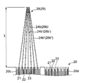
- the non-joint portions 28b, 29b of the current collecting tabs 28, 29 are gradually increased in overall length of the projecting portions 24b, 26b located on the outer side with reference to the first projecting portions 24b ', 26b' located in the center in the stacking direction. It is set as follows. Specifically, the current collecting tabs 28 and 29 are formed in a line-symmetric shape with respect to the first protrusions 24b ′ and 26b ′ positioned at the center in the stacking direction of the electrode sheets 21 and 22 of the first linear portion 20c. Yes. As shown most clearly in FIG.
- the first protrusions 24b ′ and 26b ′ are arranged so as to extend flush with the continuous electrode sheets 21 and 22, and the protruding dimension from the end 20a is the total length L.
- the other protrusions 24b and 26b are disposed so as to be inclined from the electrode sheets 21 and 22 toward the tips of the first protrusions 24b 'and 26b', and are set to dimensions that match each other.
- the junction parts 28a and 29a are formed by welding the front end side of all the protrusions 24b and 26b. Thereby, different optimal play is given to each protrusion 24b, 26b of the non-joint portion 28b, 29b forming the first bent portion 28c, 29c.
- the number of the protrusions 24b and 26b is not limited to an odd number and may be an even number. In the case of an even number, it is formed in a line-symmetric shape with respect to the pair of first protrusions 24b 'and 26b' located at the center in the stacking direction.
- the current collectors 60 ⁇ / b> A and 60 ⁇ / b> B electrically connect the current collecting tabs 28 and 29 to the external terminals 50 ⁇ / b> A and 50 ⁇ / b> B of the lid 12.
- the current collectors 60A and 60B include the first bent portions 28c and 29c of the current collecting tabs 28 and 29 in addition to the welded portions 61A and 61B that are the joined portions and the crimped portions 62A and 62B that are the connected portions. Further provided are escape portions 66A and 66B for avoiding interference.
- the welded portions 61A and 61B and the edges 63A and 63B on one end side of the crimped portions 62A and 62B are positioned on a straight line.
- the welded parts 61A and 61B and the crimped parts 62A and 62B each have a quadrangular shape in plan view.
- the width H1 of the welded portions 61A and 61B in the direction in which the current collecting tabs 28 and 29 protrude is narrower than the width H2 of the crimped portions 62A and 62B.
- the to-be-clamped portions 62A and 62B and the welded portions 61A and 61B are adjacent to the direction intersecting the direction in which the current collecting tabs 28 and 29 protrude (outside the center line B in FIG. 3).
- stepped portions for arranging the clamped parts 62A, 62B above the upper spacer 90 64A and 64B are provided.
- Current collecting tabs 28 and 29 are welded to the welded parts 61A and 61B on the lower surface 61a side opposite to the direction in which the stepped parts 64A and 64B protrude.
- the through-holes 65A and 65B through which the shaft portions 52 and the rivets 53 of the external terminals 50A and 50B pass are provided in the tightened portions 62A and 62B.
- the width H2 of the tightened portions 62A and 62B is wider than the width in the stacking direction of the straight portions 20c and 20d of the electrode body 20.
- the to-be-clamped portions 62A and 62B are located at the end 20a of the electrode body 20 across the first and second linear portions 20c and 20d.
- the escape portions 66A and 66B are provided in portions located above the first straight portions 20c of the welded portions 61A and 61B. That is, the relief portions 66A and 66B are located above the first straight portion 20c with respect to the welded portions 61A and 61B having the same width as the crimped portions 62A and 62B (the current collecting tabs 28 and 66B in FIG. 12). It is formed by providing a notch at the tip (joint portion 28a, 29a side) in the direction in which 29 protrudes.
- the upper spacer 90 as a whole has an elongated rectangular shape similar to that of the lid 12, and includes a central portion 91 and a pair of current collector housing portions extending from the central portion. 92A and 92B are provided. One end of each of the current collector housing portions 92A and 92B is coupled to the center portion 91, and the other end is coupled to the crimped portion arrangement portions 97A and 97B located on the curved portions 20e and 20e of the electrode body 20.
- the central portion 91 is provided with an opening 91 a that faces a safety valve provided on the lid 12.
- the current collector housing portions 92A and 92B are generally composed of side wall portions 93A and 93B, upper wall portions 94A and 94B extending from the upper ends of the side wall portions 93A and 93B, and upper wall portions 94A and 94B from the lower ends of the side wall portions 93A and 93B.
- Lower wall portions 95A and 95B extending in parallel.
- a current collecting tab including welded portions 61A and 61B of current collectors 60A and 60B and second bent portions 28d and 29d between upper wall portions 94A and 94B and tips 94a and 95a of lower wall portions 95A and 95B.
- the horizontally long openings 98A and 98B into which the distal ends of 28 and 29 are inserted are formed.
- the side wall portions 93A and 93B are located on the second straight portion 20d side of the electrode body 20.
- the upper wall portions 94A and 94B extend from the second straight portion 20d side to the first straight portion 20c side between the welded portions 61A and 61B of the current collectors 60A and 60B and the inner side surface 12b of the lid 12.
- the tips 94a of the upper wall portions 94A and 94B are located in the vicinity of the escape portions 66A and 66B so as to cover the welded portions 61A and 61B of the current collectors 60A and 60B.
- the lower wall portions 95A and 95B extend between the end 20a of the electrode body 20 and the current collecting tabs 28 and 29 from the second straight portion 20d side to the first straight portion 20c side.
- the tips 95a of the lower wall portions 95A and 95B are, on the first straight portion 20c of the electrode body 20, the second protrusions 24b "and 26b" located at the end on the second straight portion 20d side and the central first protrusion. It is located between 24b 'and 26b'. That is, in the upper part of the first straight part 20c, there is no lower wall part 95A, 95B, and a space in which the current collecting tabs 28, 29 can be arranged toward the opening parts 98A, 98B is formed.
- insertion grooves 96A and 96B are provided at the end portions of the upper wall portions 94A and 94B on the side to be tightened portions 97A and 97B.
- the welded portions 61A and 61B of the current collectors 60A and 60B are arranged in the current collector housing portions 92A and 92B, the step portions 64A and 64B of the current collectors 60A and 60B are positioned in the insertion grooves 96A and 96B.
- the to-be-clamped parts 62A and 62B of the current collectors 60A and 60B are positioned on the to-be-clamped part arrangement parts 97A and 97B.
- the crimped portion arrangement portions 97A and 97B include a bottom wall portion 97a and an inner peripheral wall portion 97b formed on the bottom wall portion 97a.
- the enlarged diameter portions 52a and 53b of the external terminals 50A and 50B are located inside the inner peripheral wall portion 97b.
- an outer peripheral wall portion 97c for arranging the crimped portions 62A and 62B of the current collectors 60A and 60B is further provided so as to surround the inner peripheral wall portion 97b.
- the electrode body 20 is disposed sideways so that the first straight portion 20c side from which the current collecting tabs 28 and 29 are projected is located below. Subsequently, the current collectors 60A and 60B are positioned so that the crimped portions 62A and 62B are positioned above the welded portions 61A and 61B, and the electrode body 20 is positioned on the edges 63A and 63B of the welded portions 61A and 61B. Deploy.
- the welded portions 61A and 61B of the current collectors 60A and 60B are arranged on the top surfaces of the current collector tabs 28 and 29, and the current collector tabs 28 and 29 are ultrasonically welded to the lower surface 61a side of the welded portions 61A and 61B. Connect with.
- the electrode body 20 is arranged so that the first straight portion 20c from which the current collecting tabs 28 and 29 protrude is positioned above.
- the upper packings 70A and 70B and the external terminals 50A and 50B are attached to the outer side surface 12a of the lid 12, and are arranged so that the inner side surface 12b is positioned upward.
- the lower packings 80A and 80B and the clamped portions 62A and 62B of the current collectors 60A and 60B are disposed on the inner surface 12b side of the lid 12.
- the axial part 52 and the rivet 53 of external terminal 50A, 50B are crimped, and external terminal 50A, 50B and collector 60A, 60B are electrically connected.
- the electrode body 20 and the external terminals 50A and 50B are electrically connected via the current collecting tabs 28 and 29 and the current collectors 60A and 60B.
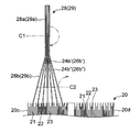
- the current collecting tabs 28, centering on the bending position C1 in the vicinity of the welded portions 61A, 61B of the current collectors 60A, 60B, 29 is bent 180 degrees.
- the bending directions of the current collecting tabs 28 and 29 are opposite to the second linear portion 20d so that the lid 12 is positioned on the upper side in the assembled state.
- the current collecting tabs 28 and 29 are bent 90 degrees around the bending position C2 on the base side.
- the bending direction of the current collecting tabs 28 and 29 is the second linear portion 20d side so that the lid 12 is positioned on the upper side in the assembled state.
- the lid 12 is arranged in parallel with the end portion 20 a of the electrode body 20.
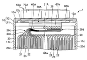
- the first bent portions 28c and 29c of the current collecting tabs 28 and 29 are located on the first straight portion 20c, and the bulged upper top portions of the current collectors 60A and 60B pass through the relief portions 66A and 66B. It is located above the lower surface 61a. That is, the tops of the first bent portions 28 c and 29 c are located between the lower surfaces (opposing surfaces) 61 a of the current collectors 60 ⁇ / b> A and 60 ⁇ / b> B facing the electrode body 20 and the lid 12 of the exterior body 10.
- the second bent portions 28d and 29d of the current collecting tabs 28 and 29 are located on the second straight portion 20d, and the welded portions 61A and 61B joined to the current collecting tabs 28 and 29 are also on the second straight portion 20d. To position.
- the upper spacer 90 is disposed on the side of the second linear portion 20d side of the electrode body 20, and is inserted between the electrode body 20 and the lid 12 from the side.
- the current collector housing portions 92 ⁇ / b> A and 92 ⁇ / b> B are disposed so that the tips 94 a and 95 a face the electrode body 20.
- the upper wall portions 94A, 94B are inserted between the welded portions 61A, 61B and the inner side surface 12b of the lid 12, and the lower wall portions 95A, 95B are connected to the current collecting tabs 28, 29 and the end 20a of the electrode body 20.
- the joined portions including the welded portions 61A and 61B and the second bent portions 28d and 29d of the current collectors 60A and 60B are arranged in the current collector housing portions 92A and 92B.
- the outer periphery of the electrode body 20 and the upper spacer 90 is covered with the insulating sheet 30, and then the electrode body 20 is accommodated together with the insulating sheet 30 in the case body 11. Finally, the lid 12 is pressed toward the case body 11 and sealed by welding the lid 12 to the opening 11 a of the case body 11.
- the base portions (non-joined portions 28b and 29b) of the current collecting tabs 28 and 29 are located on the electrode body 20 first linear portion 20c side,
- the tips (joint portions 28a, 29a) side of the tabs 28, 29 are located on the second linear portion 20d side.
- the first bent portions 28c, 29c of the current collecting tabs 28, 29 are positioned on the first linear portion 20c side, and the welded portions 61A of the current collectors 60A, 60B joined to the current collecting tabs 28, 29 are provided.
- 61B is located on the second linear portion 20d side.
- the portion where the first bent portions 28c and 29c that bulge by giving play and the portion where the bulky joining portions 28a and 29a are arranged are the end portions 20a of the electrode body 20 in the lateral direction. Adjacent to each other. Therefore, the height at the end 20a of the electrode body 20 can be reduced, and the distance between the electrode body 20 and the lid 12 can be reduced. Therefore, when the battery 1 having the same height is manufactured, the electrode body 20 can be enlarged, so that the capacity can be increased.
- the current collecting tabs 28 and 29 are formed with a total length L that can be folded back twice by the end 20a of the electrode body 20, the current collectors 60A and 60B connected to the current collecting tabs 28 and 29 are provided. And the workability when connecting the external terminals 50A and 50B can be improved. Specifically, when the shaft portions 52 and the rivets 53 of the external terminals 50 ⁇ / b> A and 50 ⁇ / b> B are crimped, the crimping device can be easily arranged so as not to contact the electrode body 20.
- the current collecting tabs 28 and 29 have the entire length L in which the second bent portions 28d and 29d are arranged in the vicinity of the welded portions 61A and 61B of the current collectors 60A and 60B, and thus the current collectors 60A and 60B and The external terminals 50A and 50B are set as short as possible after improving the assemblability. Therefore, the resistance during energization can be made as small as possible.
- the dimension L1 from the first bent portions 28c and 29c of the current collecting tabs 28 and 29 to the welded portions 61A and 61B of the current collectors 60A and 60B is determined. Since the dimension L2 to the portions 28d and 29d is increased, the current collecting tabs 28 and 29 themselves, the first bent portions 28c and 29c, and the second bent portions 28d and 29d can be made flexible. Therefore, vibrations and shocks applied to the current collecting tabs 28 and 29 can be reduced during assembling and running after the vehicle is mounted. Therefore, the current collecting tabs 28 and 29 can be prevented from extending or breaking.
- the overall lengths of the projecting portions 24b and 26b positioned on the outer side are gradually increased with reference to the first projecting portions 24b 'and 26b' at the center in the stacking direction. It is long.
- the first bent portions 28c and 29c are formed by bending the non-joined portions 28b and 29b of the current collecting tabs 28 and 29. Therefore, different optimal play can be set for each of the protrusions 24b and 26b. Therefore, it is possible to reliably prevent the protrusions 24b and 26b from extending or breaking.
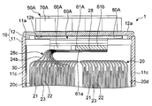
- FIG. 15 shows the battery 1 of the second embodiment.
- the second embodiment is different from the first embodiment in that the second bent portions 28d and 29d are bent at the lower portions of the welded portions 61A and 61B of the current collectors 60A and 60B.
- the same operation and effect as in the first embodiment can be obtained, and since the total length of the current collecting tabs 28 and 29 can be shortened as much as possible, the resistance during energization can be reduced. .
- the upper spacer 90 does not have to be arranged in the exterior body 10 as shown in the figure.
- the upper spacer 90 which does not provide side wall part 93A, 93B of collector collector
- FIG. 16 shows a battery 1 according to the third embodiment.
- the current collecting tabs 28 and 29 are joined to the upper surfaces 61b of the welded portions 61A and 61B of the current collectors 60A and 60B, and the edges 63A and 63B of the welded portions 61A and 61B are second folded. This is different from the first embodiment in that it is used for bending the bent portions 28d and 29d.
- the electrode body 20 when assembling the current collectors 60A and 60B to the current collector tabs 28 and 29, the electrode body 20 is placed so that the first linear portion 20c side is positioned downward, as in the first embodiment.
- the current collectors 60A and 60B are arranged in a horizontal direction so that the crimped parts 62A and 62B are positioned above the welded parts 61A and 61B.
- the electrode body 20 is disposed on the edge 63A, 63B side of the welded portions 61A, 61B, and the current collecting tabs 28, 29 are disposed on the upper surface 61b side of the welded portions 61A, 61B of the current collectors 60A, 60B. Then, the current collecting tabs 28 and 29 are connected to the upper surface 61b side of the welded parts 61A and 61B by ultrasonic welding.
- the current collectors 60A and 60B connected to the current collecting tabs 28 and 29 are connected to the lid 12 on which the upper packings 70A and 70B, the external terminals 50A and 50B, and the lower packings 80A and 80B are arranged.
- the current collectors 60A, 60B and the external terminals 50A, 50B are connected by caulking.
- the current collecting tabs 28 and 29 are bent and the lid 12 is disposed on the end portion 20a of the electrode body 20.
- the current collecting tabs 28 are first wound around the edges 63A and 63B of the current collectors 60A and 60B. 29 are bent to form second bent portions 28d and 29d.
- the current collecting tabs 28 and 29 are bent 90 degrees on the base side, and the lid 12 is disposed on the end 20 a of the electrode body 20.
- the insulating sheet 30 is disposed on the outer peripheral portion.
- the electrode body 20 is disposed inside the case body 11, and the opening 11 a of the case body 11 is sealed with the lid 12.
- the third embodiment it is possible to obtain the same operations and effects as in the first embodiment. Moreover, since the second bent portions 28d and 29d can be formed so as to be wound around the current collectors 60A and 60B, workability can be improved. Further, as in the second embodiment, the total length of the current collecting tabs 28 and 29 can be shortened as much as possible. Further, since the current collecting tabs 28 and 29 do not come into contact with the exterior body 10, a configuration in which the upper spacer 90 is not disposed in the exterior body 10 or the side wall portions 93A and 93B of the current collector housing portions 92A and 92B are provided. There may be no configuration.
- the battery 1 of the present invention is not limited to the above embodiment, and various modifications can be made.
- the current collecting tabs 28 and 29 are bent twice between the electrode body 20 and the lid 12, but may be bent only once (first bent portions 28c and 29c) as shown in FIG. Good. Further, it may be bent three or more times. That is, in the current collectors 60A and 60B, the first bent portions 28c and 29c are arranged on the first straight portion 20c side from which the current collecting tabs 28 and 29 are projected, and the current collecting tabs 28 and 29 are not projected second. If the welded portions 61A and 61B of the current collectors 60A and 60B are arranged on the straight line portion 20d side, the number of times the current collecting tabs 28 and 29 are bent can be changed as desired.
- the current collecting tabs 28 and 29 are set so that the overall lengths of the protrusions 24b and 26b positioned on the outside gradually increase, but the total lengths of all the protrusions 24b and 26b are set to be the same. Also good. Moreover, although the projections 24b and 26b are welded to form the joined portions 28a and 29a and the non-joined portions 28b and 29b, the joined portions 28a and 29a may not be formed in advance.
- the electrode body 20 is housed in the case body 11 so that the current collecting tabs 28 and 29 are located on the opening 11a side, but the current collecting tabs 28 and 29 are located on the one short side wall portion 11d side. It may be accommodated in the case main body 11. In this case, the external terminals 50 ⁇ / b> A and 50 ⁇ / b> B may be arranged on the case body 11.
- the present invention is not limited to the wound electrode body 20 around which the belt-shaped positive electrode sheet 21, the negative electrode sheet 22, and the separator 23 are wound with the winding axis A as the center, and the rectangular positive electrode
- the present invention can also be applied to a laminated electrode body in which an electrode sheet, a negative electrode sheet, and a separator are laminated in one direction.
- the present invention is not limited to a secondary battery such as a non-electrolyte secondary battery including a lithium ion battery, and can be applied to various power storage elements including a primary battery and a capacitor.
Abstract
Description
図1及び図2は、本発明の第1実施形態に係るリチウムイオン二次電池(以下、単に電池という)1を示す。
図1及び図2を参照すると、電池1は、外装体10、電極体20、絶縁シート30、底部スペーサ40、正極及び負極の外部端子50A,50B、正負の集電体60A,60B、上側パッキン70A,70B、下側パッキン80A,80B、及び上部スペーサ90を備える。
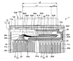
図10に最も明瞭に示すように、集電タブ28,29は、巻回により電極シート21,22が積層された一対の直線部20c,20dのうち、基部側が一方側の直線部(第1部分)20cに位置し、他方側の直線部(第2部分)20dに向けて折り曲げられて、先端側が直線部20d側で電極シート21,22の積層方向に配置された集電体60A,60Bと電気的に接続されている。
図10に加えて図7及び図12を参照すると、集電体60A,60Bは、集電タブ28,29を蓋12の外部端子50A,50Bに電気的に接続させる。集電体60A,60Bは、被接合部である被溶接部61A,61B及び接続部である被加締部62A,62Bに加え、集電タブ28,29の第1折曲部28c,29cの干渉を回避する逃がし部66A,66Bを更に備える。
図10に加えて図9及び図13A,Bを参照すると、上部スペーサ90は、全体として蓋12と同様の細長い矩形状であり、中央部91と、中央部から延びる一対の集電体収容部92A,92Bを備える。集電体収容部92A,92Bは、一端が中央部91に連結され、他端が電極体20の湾曲部20e,20e上に位置する被加締部配置部97A,97Bに連結されている。中央部91には、蓋12に設けられた安全弁と対向する開口91aが設けられている。
図15は第2実施形態の電池1を示す。この第2実施形態では、第2折曲部28d,29dを集電体60A,60Bの被溶接部61A,61Bの下部で折り曲げるようにした点で、第1実施形態と相違する。この第2実施形態では、第1実施形態と同様の作用及び効果を得ることができるうえ、集電タブ28,29の全長を可能な限り短くできるため、通電時の抵抗を小さくすることができる。また、集電体60A,60Bに接続した集電タブ28,29が外装体10に接触することが無いため、図示のように、外装体10内に上部スペーサ90を配置しなくてもよい。又は、集電体収容部92A,92Bの側壁部93A,93Bを設けていない上部スペーサ90を用いてもよい。よって、部品点数を削減又は上部スペーサ90の構造を簡素化できるため、コストダウンを図ることができる。
図16は第3実施形態の電池1を示す。この第3実施形態では、集電タブ28,29を集電体60A,60Bの被溶接部61A,61Bの上面61b側に接合し、被溶接部61A,61Bの縁63A,63Bを第2折曲部28d,29dの折り曲げに利用した点で、第1実施形態と相違する。
10 外装体(ケース)
11 ケース本体
11a 開口
11b 底壁部
11c 長側壁部
11d 短側壁部
12 蓋
12a 外側面
12b 内側面
20 電極体
20a 端部
20b 端部
20c 第1直線部
20d 第2直線部
20e 湾曲部
21 正極電極シート
22 負極電極シート
23 セパレータ
24 正極金属箔
24a 未塗工部
24b 突部
24b’ 第1突部
24b” 第2突部
25 正極活物質層
26 負極金属箔
26a 未塗工部
26b 突部
26b’ 第1突部
26b” 第2突部
27 負極活物質層
28 正極の集電タブ
28a 接合部
28b 非接合部
28c 第1折曲部
28d 第2折曲部
29 負極の集電タブ
29a 接合部
29b 非接合部
29c 第1折曲部
29d 第2折曲部
30 絶縁シート
40 底部スペーサ
50A,50B 外部端子
51A,51B 板状部
52 軸部
52a 拡径部
53 リベット
53a 顎部
53b 拡径部
60A,60B 集電体
61A,61B 被溶接部(被接合部)
61a 下面
61b 上面
62A,62B 被加締部
63A,63B 縁
64A,64B 段部
65A,65B 貫通孔
66A,66B 逃がし部
70A,70B 上側パッキン
80A,80B 下側パッキン
90 上部スペーサ
91 中央部
91a 開口
92A,92B 集電体収容部
93A,93B 側壁部
94A,94B 上壁部
94a 先端
95A,95B 下壁部
95a 先端
96A,96B 挿通溝
97A,97B 被加締部配置部
97a 底壁部
97b 内側周壁部
97c 外側周壁部
98A,98B 開口部
A 巻回軸
B 中心線
C1,C2 折曲位置
Claims (8)
- セパレータを介在させて交互に積層した正極電極シート及び負極電極シートと、前記各電極シートの積層方向の一方側の第1部分から突出した複数の突部からなる正極集電タブ及び負極集電タブとを有し、ケース内に収容された電極体と、
前記ケースに配置された正極外部端子及び負極外部端子と、
前記電極体と前記ケースとの間に配置され、前記各外部端子に電気的に接続されているとともに、前記各電極シートの積層方向の他方側の第2部分側で前記各電極シートの積層方向に配置された前記各集電タブにそれぞれ電気的に接続された正極集電体及び負極集電体と
を備える、蓄電素子。 - 前記電極体は、前記正極電極シートと前記負極電極シートとの間に前記セパレータが介在するように重ね合わせて巻回軸回りに巻回されており、前記巻回軸が延びる方向から見た端部が、互いに対向する一対の直線部と、これらの直線部を接続するように互いに対向する一対の湾曲部とを有する長円状であり、
前記一対の直線部のうち、前記第1部分である一方側の第1直線部に、前記正極集電タブ及び前記負極集電タブが前記第1直線部が延びる方向に間隔をあけて配置され、前記第2部分である他方側の第2直線部側で前記各集電タブと前記各集電体とが接続されている、請求項1に記載の蓄電素子。 - 前記集電タブは、前記電極シート側に位置し前記第1部分側から前記第2部分側へ向けて折り曲げられた第1折曲部と、前記集電体側に位置し前記第2部分側から前記第1部分側へ向けて折り曲げられた第2折曲部とを含む2以上の折曲部を有する、請求項1又は請求項2に記載の蓄電素子。
- 前記集電タブの前記第2折曲部は、前記集電体と前記ケースとの間に配置されており、かつ、前記集電タブの前記第1折曲部から前記接続部までの寸法よりも前記集電タブの前記第1折曲部から前記第2折曲部までの寸法が長くされている、請求項3に記載の蓄電素子。
- 前記集電タブは、前記電極シートの積層方向の中心に位置する第1突部を基準とし、前記第1突部の先端に向けて他の突部を傾斜させて配置した状態で互いに接合されている、請求項4に記載の蓄電素子。
- 前記集電タブの前記第1折曲部は、前記集電体側に膨出している頂部が、前記電極体と対向する前記集電体の対向面と前記ケースとの間に位置している、請求項3から請求項5のいずれか1項に記載の蓄電素子。
- 前記集電タブは、前記第1部分側から前記第2部分側へ向けて折り曲げられた第1折曲部を有し、
前記第1折曲部は、前記集電体側に膨出している頂部が、前記電極体と対向する前記集電体の対向面と前記ケースとの間に位置している、請求項1又は請求項2に記載の蓄電素子。 - 前記集電体には、前記第1折曲部の前記頂部が配置される逃がし部が設けられている、請求項6又は請求項7に記載の蓄電素子。
Priority Applications (5)
| Application Number | Priority Date | Filing Date | Title |
|---|---|---|---|
| EP22155819.0A EP4016569A1 (en) | 2014-12-11 | 2015-12-11 | Power storage element |
| US15/534,462 US20170365839A1 (en) | 2014-12-11 | 2015-12-11 | Energy storage device |
| EP15867813.6A EP3232495B1 (en) | 2014-12-11 | 2015-12-11 | Power storage element |
| JP2016563745A JP6665789B2 (ja) | 2014-12-11 | 2015-12-11 | 蓄電素子 |
| CN201580072645.9A CN107112488B (zh) | 2014-12-11 | 2015-12-11 | 蓄电元件 |
Applications Claiming Priority (2)
| Application Number | Priority Date | Filing Date | Title |
|---|---|---|---|
| JP2014-250606 | 2014-12-11 | ||
| JP2014250606 | 2014-12-11 |
Publications (1)
| Publication Number | Publication Date |
|---|---|
| WO2016093338A1 true WO2016093338A1 (ja) | 2016-06-16 |
Family
ID=56107515
Family Applications (1)
| Application Number | Title | Priority Date | Filing Date |
|---|---|---|---|
| PCT/JP2015/084758 WO2016093338A1 (ja) | 2014-12-11 | 2015-12-11 | 蓄電素子 |
Country Status (5)
| Country | Link |
|---|---|
| US (1) | US20170365839A1 (ja) |
| EP (2) | EP4016569A1 (ja) |
| JP (1) | JP6665789B2 (ja) |
| CN (2) | CN111430654A (ja) |
| WO (1) | WO2016093338A1 (ja) |
Cited By (7)
| Publication number | Priority date | Publication date | Assignee | Title |
|---|---|---|---|---|
| JP2017157354A (ja) * | 2016-02-29 | 2017-09-07 | リチウム エナジー アンド パワー ゲゼルシャフト ミット ベシュレンクテル ハフッング ウント コンパニー コマンディトゲゼルシャフトLithium Energy and Power GmbH & Co. KG | 蓄電素子及び蓄電素子の製造方法 |
| CN107275090A (zh) * | 2017-08-15 | 2017-10-20 | 湖南艾华集团股份有限公司 | 一种方形电容器 |
| JP2018006114A (ja) * | 2016-06-30 | 2018-01-11 | 株式会社豊田自動織機 | 蓄電装置 |
| KR20190046089A (ko) * | 2017-10-25 | 2019-05-07 | (주)오렌지파워 | 일방향 단자부를 구비한 중공형 이차전지 |
| WO2019163220A1 (ja) * | 2018-02-21 | 2019-08-29 | パナソニック株式会社 | 角形二次電池 |
| EP3514876A4 (en) * | 2016-11-02 | 2019-11-06 | LG Chem, Ltd. | ELECTRONIC ARRANGEMENT AND METHOD FOR THE MANUFACTURE THEREOF |
| WO2022123680A1 (ja) * | 2020-12-09 | 2022-06-16 | 株式会社 東芝 | 電池 |
Families Citing this family (8)
| Publication number | Priority date | Publication date | Assignee | Title |
|---|---|---|---|---|
| WO2019026672A1 (ja) * | 2017-08-03 | 2019-02-07 | エリーパワー株式会社 | 密閉型電池、組電池及び密閉型電池の製造方法 |
| CN113451713B (zh) * | 2017-08-30 | 2024-03-19 | 宁德时代新能源科技股份有限公司 | 二次电池以及电池模组 |
| KR102659830B1 (ko) * | 2018-01-09 | 2024-04-23 | 삼성에스디아이 주식회사 | 이차 전지 및 그 제조 방법 |
| JP7121899B2 (ja) * | 2018-02-16 | 2022-08-19 | トヨタ自動車株式会社 | 電池および電池の製造方法 |
| JP7300266B2 (ja) * | 2018-12-27 | 2023-06-29 | 三洋電機株式会社 | 二次電池 |
| JP7047978B2 (ja) * | 2019-08-08 | 2022-04-05 | 株式会社村田製作所 | 二次電池、電池パック、電子機器、電動工具及び電動車両 |
| CN112331974A (zh) * | 2020-11-24 | 2021-02-05 | 江苏阿李动力科技有限公司 | 一种新型动力电池顶盖及其加工工艺 |
| JP2023142802A (ja) * | 2022-03-25 | 2023-10-05 | 株式会社東芝 | 二次電池 |
Citations (6)
| Publication number | Priority date | Publication date | Assignee | Title |
|---|---|---|---|---|
| JP2002246009A (ja) * | 2001-02-19 | 2002-08-30 | Sanyo Electric Co Ltd | アルカリ蓄電池 |
| JP2005005215A (ja) * | 2003-06-13 | 2005-01-06 | Mitsubishi Heavy Ind Ltd | 二次電池、二次電池の製造方法 |
| JP2011070918A (ja) * | 2009-09-25 | 2011-04-07 | Toshiba Corp | 電池 |
| US20110151295A1 (en) * | 2009-12-17 | 2011-06-23 | Kwang-Chun Kim | Electrode assembly and secondary battery using the same |
| JP2013161757A (ja) * | 2012-02-08 | 2013-08-19 | Toyota Industries Corp | 蓄電装置及び車両 |
| JP2015130251A (ja) * | 2014-01-06 | 2015-07-16 | 株式会社東芝 | 電池 |
Family Cites Families (8)
| Publication number | Priority date | Publication date | Assignee | Title |
|---|---|---|---|---|
| JP4780598B2 (ja) * | 2004-09-29 | 2011-09-28 | 日立マクセルエナジー株式会社 | 密閉角形電池 |
| JP5114036B2 (ja) * | 2006-09-08 | 2013-01-09 | Necエナジーデバイス株式会社 | 積層型電池の製造方法 |
| CN102315409A (zh) * | 2011-08-29 | 2012-01-11 | 潍坊威能环保电源有限公司 | 一种锂离子动力电池 |
| KR101517054B1 (ko) * | 2012-04-16 | 2015-05-06 | 주식회사 엘지화학 | 양극과 음극의 용접 부위 형상이 다른 전극조립체 및 이를 포함하는 이차전지 |
| JP2014075330A (ja) * | 2012-09-12 | 2014-04-24 | Toyota Industries Corp | 蓄電装置 |
| JP6173730B2 (ja) * | 2013-03-14 | 2017-08-02 | 株式会社東芝 | 電池 |
| KR20150115558A (ko) * | 2014-04-04 | 2015-10-14 | 삼성에스디아이 주식회사 | 보호회로모듈을 갖는 이차 전지 |
| KR102306440B1 (ko) * | 2014-08-14 | 2021-09-29 | 삼성에스디아이 주식회사 | 이차 전지 |
-
2015
- 2015-12-11 US US15/534,462 patent/US20170365839A1/en not_active Abandoned
- 2015-12-11 EP EP22155819.0A patent/EP4016569A1/en active Pending
- 2015-12-11 EP EP15867813.6A patent/EP3232495B1/en active Active
- 2015-12-11 WO PCT/JP2015/084758 patent/WO2016093338A1/ja active Application Filing
- 2015-12-11 CN CN202010248016.XA patent/CN111430654A/zh active Pending
- 2015-12-11 CN CN201580072645.9A patent/CN107112488B/zh active Active
- 2015-12-11 JP JP2016563745A patent/JP6665789B2/ja active Active
Patent Citations (6)
| Publication number | Priority date | Publication date | Assignee | Title |
|---|---|---|---|---|
| JP2002246009A (ja) * | 2001-02-19 | 2002-08-30 | Sanyo Electric Co Ltd | アルカリ蓄電池 |
| JP2005005215A (ja) * | 2003-06-13 | 2005-01-06 | Mitsubishi Heavy Ind Ltd | 二次電池、二次電池の製造方法 |
| JP2011070918A (ja) * | 2009-09-25 | 2011-04-07 | Toshiba Corp | 電池 |
| US20110151295A1 (en) * | 2009-12-17 | 2011-06-23 | Kwang-Chun Kim | Electrode assembly and secondary battery using the same |
| JP2013161757A (ja) * | 2012-02-08 | 2013-08-19 | Toyota Industries Corp | 蓄電装置及び車両 |
| JP2015130251A (ja) * | 2014-01-06 | 2015-07-16 | 株式会社東芝 | 電池 |
Non-Patent Citations (1)
| Title |
|---|
| See also references of EP3232495A4 * |
Cited By (11)
| Publication number | Priority date | Publication date | Assignee | Title |
|---|---|---|---|---|
| JP2017157354A (ja) * | 2016-02-29 | 2017-09-07 | リチウム エナジー アンド パワー ゲゼルシャフト ミット ベシュレンクテル ハフッング ウント コンパニー コマンディトゲゼルシャフトLithium Energy and Power GmbH & Co. KG | 蓄電素子及び蓄電素子の製造方法 |
| JP2018006114A (ja) * | 2016-06-30 | 2018-01-11 | 株式会社豊田自動織機 | 蓄電装置 |
| EP3514876A4 (en) * | 2016-11-02 | 2019-11-06 | LG Chem, Ltd. | ELECTRONIC ARRANGEMENT AND METHOD FOR THE MANUFACTURE THEREOF |
| US10700384B2 (en) | 2016-11-02 | 2020-06-30 | Lg Chem, Ltd. | Electrode assembly and method for manufacturing the same |
| CN107275090A (zh) * | 2017-08-15 | 2017-10-20 | 湖南艾华集团股份有限公司 | 一种方形电容器 |
| KR20190046089A (ko) * | 2017-10-25 | 2019-05-07 | (주)오렌지파워 | 일방향 단자부를 구비한 중공형 이차전지 |
| KR102012674B1 (ko) * | 2017-10-25 | 2019-08-23 | 주식회사 한국배터리검사서비스 | 일방향 단자부를 구비한 중공형 이차전지 |
| WO2019163220A1 (ja) * | 2018-02-21 | 2019-08-29 | パナソニック株式会社 | 角形二次電池 |
| JPWO2019163220A1 (ja) * | 2018-02-21 | 2021-02-04 | パナソニック株式会社 | 角形二次電池 |
| JP7358329B2 (ja) | 2018-02-21 | 2023-10-10 | パナソニックホールディングス株式会社 | 角形二次電池 |
| WO2022123680A1 (ja) * | 2020-12-09 | 2022-06-16 | 株式会社 東芝 | 電池 |
Also Published As
| Publication number | Publication date |
|---|---|
| EP3232495A4 (en) | 2018-08-01 |
| CN107112488B (zh) | 2020-04-21 |
| CN111430654A (zh) | 2020-07-17 |
| JP6665789B2 (ja) | 2020-03-13 |
| US20170365839A1 (en) | 2017-12-21 |
| EP4016569A1 (en) | 2022-06-22 |
| JPWO2016093338A1 (ja) | 2017-09-21 |
| EP3232495B1 (en) | 2022-03-16 |
| CN107112488A (zh) | 2017-08-29 |
| EP3232495A1 (en) | 2017-10-18 |
Similar Documents
| Publication | Publication Date | Title |
|---|---|---|
| WO2016093338A1 (ja) | 蓄電素子 | |
| JP6520097B2 (ja) | 蓄電素子 | |
| KR100637443B1 (ko) | 이차 전지와 이에 사용되는 단자 조립체 | |
| JP6124175B2 (ja) | 蓄電素子 | |
| CN109326813B (zh) | 蓄电装置以及绝缘保持器 | |
| JP6225421B2 (ja) | 蓄電素子、及び、蓄電素子の製造方法 | |
| JP6702303B2 (ja) | 蓄電装置 | |
| JP2009277604A (ja) | 非水電解質二次電池 | |
| JP6550848B2 (ja) | 角形二次電池 | |
| JP6011344B2 (ja) | 蓄電素子 | |
| JP6891930B2 (ja) | 角形二次電池及びそれを用いた組電池 | |
| WO2015076183A1 (ja) | 蓄電装置 | |
| KR20130098135A (ko) | 집전 부재를 구비하는 축전 소자 및 집전 부재의 제조 방법 | |
| JP5810861B2 (ja) | 電池 | |
| JP4210896B2 (ja) | 密閉形電池 | |
| JP6787650B2 (ja) | 蓄電素子及びその製造方法 | |
| JP6213036B2 (ja) | 蓄電素子及びその製造方法 | |
| WO2015146584A1 (ja) | 蓄電装置 | |
| JP2023108022A (ja) | 二次電池 | |
| JP6657810B2 (ja) | 蓄電装置の製造方法、及び蓄電装置 | |
| JP2017084540A (ja) | 蓄電素子 | |
| WO2019131356A1 (ja) | 蓄電装置 | |
| JP6507612B2 (ja) | 蓄電素子 | |
| JP6001885B2 (ja) | 扁平形電池 | |
| JPWO2018235768A1 (ja) | 蓄電素子 |
Legal Events
| Date | Code | Title | Description |
|---|---|---|---|
| 121 | Ep: the epo has been informed by wipo that ep was designated in this application |
Ref document number: 15867813 Country of ref document: EP Kind code of ref document: A1 |
|
| ENP | Entry into the national phase |
Ref document number: 2016563745 Country of ref document: JP Kind code of ref document: A |
|
| WWE | Wipo information: entry into national phase |
Ref document number: 15534462 Country of ref document: US |
|
| REEP | Request for entry into the european phase |
Ref document number: 2015867813 Country of ref document: EP |
|
| NENP | Non-entry into the national phase |
Ref country code: DE |