WO2016075856A1 - 車載用電源装置およびそれを搭載した車両 - Google Patents
車載用電源装置およびそれを搭載した車両 Download PDFInfo
- Publication number
- WO2016075856A1 WO2016075856A1 PCT/JP2015/004837 JP2015004837W WO2016075856A1 WO 2016075856 A1 WO2016075856 A1 WO 2016075856A1 JP 2015004837 W JP2015004837 W JP 2015004837W WO 2016075856 A1 WO2016075856 A1 WO 2016075856A1
- Authority
- WO
- WIPO (PCT)
- Prior art keywords
- voltage
- boost converter
- converter unit
- output terminal
- vehicle
- Prior art date
Links
Images


Classifications
-
- B—PERFORMING OPERATIONS; TRANSPORTING
- B60—VEHICLES IN GENERAL
- B60R—VEHICLES, VEHICLE FITTINGS, OR VEHICLE PARTS, NOT OTHERWISE PROVIDED FOR
- B60R16/00—Electric or fluid circuits specially adapted for vehicles and not otherwise provided for; Arrangement of elements of electric or fluid circuits specially adapted for vehicles and not otherwise provided for
- B60R16/02—Electric or fluid circuits specially adapted for vehicles and not otherwise provided for; Arrangement of elements of electric or fluid circuits specially adapted for vehicles and not otherwise provided for electric constitutive elements
- B60R16/03—Electric or fluid circuits specially adapted for vehicles and not otherwise provided for; Arrangement of elements of electric or fluid circuits specially adapted for vehicles and not otherwise provided for electric constitutive elements for supply of electrical power to vehicle subsystems or for
- B60R16/033—Electric or fluid circuits specially adapted for vehicles and not otherwise provided for; Arrangement of elements of electric or fluid circuits specially adapted for vehicles and not otherwise provided for electric constitutive elements for supply of electrical power to vehicle subsystems or for characterised by the use of electrical cells or batteries
-
- B—PERFORMING OPERATIONS; TRANSPORTING
- B60—VEHICLES IN GENERAL
- B60L—PROPULSION OF ELECTRICALLY-PROPELLED VEHICLES; SUPPLYING ELECTRIC POWER FOR AUXILIARY EQUIPMENT OF ELECTRICALLY-PROPELLED VEHICLES; ELECTRODYNAMIC BRAKE SYSTEMS FOR VEHICLES IN GENERAL; MAGNETIC SUSPENSION OR LEVITATION FOR VEHICLES; MONITORING OPERATING VARIABLES OF ELECTRICALLY-PROPELLED VEHICLES; ELECTRIC SAFETY DEVICES FOR ELECTRICALLY-PROPELLED VEHICLES
- B60L1/00—Supplying electric power to auxiliary equipment of vehicles
-
- B—PERFORMING OPERATIONS; TRANSPORTING
- B60—VEHICLES IN GENERAL
- B60L—PROPULSION OF ELECTRICALLY-PROPELLED VEHICLES; SUPPLYING ELECTRIC POWER FOR AUXILIARY EQUIPMENT OF ELECTRICALLY-PROPELLED VEHICLES; ELECTRODYNAMIC BRAKE SYSTEMS FOR VEHICLES IN GENERAL; MAGNETIC SUSPENSION OR LEVITATION FOR VEHICLES; MONITORING OPERATING VARIABLES OF ELECTRICALLY-PROPELLED VEHICLES; ELECTRIC SAFETY DEVICES FOR ELECTRICALLY-PROPELLED VEHICLES
- B60L3/00—Electric devices on electrically-propelled vehicles for safety purposes; Monitoring operating variables, e.g. speed, deceleration or energy consumption
- B60L3/0023—Detecting, eliminating, remedying or compensating for drive train abnormalities, e.g. failures within the drive train
- B60L3/003—Detecting, eliminating, remedying or compensating for drive train abnormalities, e.g. failures within the drive train relating to inverters
-
- B—PERFORMING OPERATIONS; TRANSPORTING
- B60—VEHICLES IN GENERAL
- B60L—PROPULSION OF ELECTRICALLY-PROPELLED VEHICLES; SUPPLYING ELECTRIC POWER FOR AUXILIARY EQUIPMENT OF ELECTRICALLY-PROPELLED VEHICLES; ELECTRODYNAMIC BRAKE SYSTEMS FOR VEHICLES IN GENERAL; MAGNETIC SUSPENSION OR LEVITATION FOR VEHICLES; MONITORING OPERATING VARIABLES OF ELECTRICALLY-PROPELLED VEHICLES; ELECTRIC SAFETY DEVICES FOR ELECTRICALLY-PROPELLED VEHICLES
- B60L3/00—Electric devices on electrically-propelled vehicles for safety purposes; Monitoring operating variables, e.g. speed, deceleration or energy consumption
- B60L3/12—Recording operating variables ; Monitoring of operating variables
-
- B—PERFORMING OPERATIONS; TRANSPORTING
- B60—VEHICLES IN GENERAL
- B60Q—ARRANGEMENT OF SIGNALLING OR LIGHTING DEVICES, THE MOUNTING OR SUPPORTING THEREOF OR CIRCUITS THEREFOR, FOR VEHICLES IN GENERAL
- B60Q9/00—Arrangement or adaptation of signal devices not provided for in one of main groups B60Q1/00 - B60Q7/00, e.g. haptic signalling
-
- B—PERFORMING OPERATIONS; TRANSPORTING
- B60—VEHICLES IN GENERAL
- B60R—VEHICLES, VEHICLE FITTINGS, OR VEHICLE PARTS, NOT OTHERWISE PROVIDED FOR
- B60R16/00—Electric or fluid circuits specially adapted for vehicles and not otherwise provided for; Arrangement of elements of electric or fluid circuits specially adapted for vehicles and not otherwise provided for
- B60R16/005—Electro-mechanical devices, e.g. switched
-
- H—ELECTRICITY
- H02—GENERATION; CONVERSION OR DISTRIBUTION OF ELECTRIC POWER
- H02M—APPARATUS FOR CONVERSION BETWEEN AC AND AC, BETWEEN AC AND DC, OR BETWEEN DC AND DC, AND FOR USE WITH MAINS OR SIMILAR POWER SUPPLY SYSTEMS; CONVERSION OF DC OR AC INPUT POWER INTO SURGE OUTPUT POWER; CONTROL OR REGULATION THEREOF
- H02M3/00—Conversion of dc power input into dc power output
- H02M3/02—Conversion of dc power input into dc power output without intermediate conversion into ac
- H02M3/04—Conversion of dc power input into dc power output without intermediate conversion into ac by static converters
- H02M3/10—Conversion of dc power input into dc power output without intermediate conversion into ac by static converters using discharge tubes with control electrode or semiconductor devices with control electrode
- H02M3/145—Conversion of dc power input into dc power output without intermediate conversion into ac by static converters using discharge tubes with control electrode or semiconductor devices with control electrode using devices of a triode or transistor type requiring continuous application of a control signal
- H02M3/155—Conversion of dc power input into dc power output without intermediate conversion into ac by static converters using discharge tubes with control electrode or semiconductor devices with control electrode using devices of a triode or transistor type requiring continuous application of a control signal using semiconductor devices only
- H02M3/156—Conversion of dc power input into dc power output without intermediate conversion into ac by static converters using discharge tubes with control electrode or semiconductor devices with control electrode using devices of a triode or transistor type requiring continuous application of a control signal using semiconductor devices only with automatic control of output voltage or current, e.g. switching regulators
-
- B—PERFORMING OPERATIONS; TRANSPORTING
- B60—VEHICLES IN GENERAL
- B60L—PROPULSION OF ELECTRICALLY-PROPELLED VEHICLES; SUPPLYING ELECTRIC POWER FOR AUXILIARY EQUIPMENT OF ELECTRICALLY-PROPELLED VEHICLES; ELECTRODYNAMIC BRAKE SYSTEMS FOR VEHICLES IN GENERAL; MAGNETIC SUSPENSION OR LEVITATION FOR VEHICLES; MONITORING OPERATING VARIABLES OF ELECTRICALLY-PROPELLED VEHICLES; ELECTRIC SAFETY DEVICES FOR ELECTRICALLY-PROPELLED VEHICLES
- B60L2210/00—Converter types
- B60L2210/10—DC to DC converters
- B60L2210/14—Boost converters
-
- B—PERFORMING OPERATIONS; TRANSPORTING
- B60—VEHICLES IN GENERAL
- B60L—PROPULSION OF ELECTRICALLY-PROPELLED VEHICLES; SUPPLYING ELECTRIC POWER FOR AUXILIARY EQUIPMENT OF ELECTRICALLY-PROPELLED VEHICLES; ELECTRODYNAMIC BRAKE SYSTEMS FOR VEHICLES IN GENERAL; MAGNETIC SUSPENSION OR LEVITATION FOR VEHICLES; MONITORING OPERATING VARIABLES OF ELECTRICALLY-PROPELLED VEHICLES; ELECTRIC SAFETY DEVICES FOR ELECTRICALLY-PROPELLED VEHICLES
- B60L2240/00—Control parameters of input or output; Target parameters
- B60L2240/40—Drive Train control parameters
- B60L2240/52—Drive Train control parameters related to converters
- B60L2240/527—Voltage
-
- B—PERFORMING OPERATIONS; TRANSPORTING
- B60—VEHICLES IN GENERAL
- B60L—PROPULSION OF ELECTRICALLY-PROPELLED VEHICLES; SUPPLYING ELECTRIC POWER FOR AUXILIARY EQUIPMENT OF ELECTRICALLY-PROPELLED VEHICLES; ELECTRODYNAMIC BRAKE SYSTEMS FOR VEHICLES IN GENERAL; MAGNETIC SUSPENSION OR LEVITATION FOR VEHICLES; MONITORING OPERATING VARIABLES OF ELECTRICALLY-PROPELLED VEHICLES; ELECTRIC SAFETY DEVICES FOR ELECTRICALLY-PROPELLED VEHICLES
- B60L2250/00—Driver interactions
- B60L2250/10—Driver interactions by alarm
-
- Y—GENERAL TAGGING OF NEW TECHNOLOGICAL DEVELOPMENTS; GENERAL TAGGING OF CROSS-SECTIONAL TECHNOLOGIES SPANNING OVER SEVERAL SECTIONS OF THE IPC; TECHNICAL SUBJECTS COVERED BY FORMER USPC CROSS-REFERENCE ART COLLECTIONS [XRACs] AND DIGESTS
- Y02—TECHNOLOGIES OR APPLICATIONS FOR MITIGATION OR ADAPTATION AGAINST CLIMATE CHANGE
- Y02T—CLIMATE CHANGE MITIGATION TECHNOLOGIES RELATED TO TRANSPORTATION
- Y02T10/00—Road transport of goods or passengers
- Y02T10/60—Other road transportation technologies with climate change mitigation effect
- Y02T10/72—Electric energy management in electromobility
Definitions
- the present invention relates to an in-vehicle power supply device used for various vehicles and a vehicle equipped with the same.
- FIG. 5 is a circuit block diagram of a vehicle-mounted power supply device 500 in a vehicle having a conventional idling stop function.
- FIG. 6 is a timing chart of the output voltage of the in-vehicle power supply device 500.
- the positive electrode side of the storage battery 1 is connected to the input terminal 2 a of the power circuit 2 via the fuse 3, and the output terminal 2 b of the power circuit 2 is connected to the load 4.
- a boost converter 5, an energization assist diode 6, and a switch 7 are arranged in parallel and connected to an input terminal 2a and an output terminal 2b.
- the anode side of the conduction auxiliary diode 6 is connected to the input terminal 2 a of the power supply circuit 2, and the cathode side of the conduction auxiliary diode 6 is connected to the output terminal 2 b of the power supply circuit 2.
- the boost converter 5 of the power supply circuit 2 is capable of stably restarting the vehicle by boosting the voltage of the storage battery 1 when the vehicle restarts from an idling stop state.
- the switch 7 is opened only when the boost converter 5 performs a boost operation.
- the control device 8 provided in the vehicle controls the boost converter 5 and the switch 7.
- an energization assist diode 6 of the power supply circuit 2 is provided in order to prevent the boosted voltage from being supplied to the input terminal 2a when the boosting converter 5 is performing a boosting operation, and even if the switch 7 is left open in a state of being damaged for some reason.
- an energization assist diode 6 of the power supply circuit 2 is provided in order for the storage battery 1 to supply power to the load 4. That is, the power of the storage battery 1 can be supplied to the load 4 if either the current-carrying diode 6 or the switch 7 is in a normal state.
- the power supply circuit 2 has a function of determining whether the boost converter 5 is operating normally.
- the determination of the normal operating state of the boost converter 5 in the power supply circuit 2 uses the voltage at the output terminal 2b during non-boosting and boosting, which will be described below.
- the control device 8 instructs to stop the operation of the boost converter 5 at the time of non-boosting and to close (turn on) the switch 7. In this case, the control device 8 detects the voltage of the output terminal 2b and stores the detected voltage value.
- the control device 8 instructs the boost converter 5 and the switch 7 to operate the boost converter 5 at the time of boosting and to open (turn off) the switch 7. In this case, the control device 8 detects the voltage of the output terminal 2b and stores the value of this voltage.
- control device 8 obtains a difference between the voltage value of the output terminal 2b at the time of non-boosting and the voltage value of the output terminal 2b at the time of boosting. With the above operation, control device 8 compares this difference with a predetermined threshold value V0 to determine whether boost converter 5 is operating normally.
- a vehicle-mounted power supply device similar to the vehicle-mounted power supply device 500 is disclosed in Patent Document 1, for example.
- the in-vehicle power supply device includes a boost converter unit that performs a boost operation for boosting a voltage supplied from an input terminal, an energizing auxiliary diode connected in parallel with the boost converter unit, and a boost converter unit and an energizing auxiliary diode connected in parallel.
- the control unit detects the voltage output from the output terminal as the first voltage by instructing the switch element and the boost converter unit to open the switch element and stop the operation of the boost converter unit. After detecting the first voltage at the output terminal, the control unit outputs the output from the output terminal by continuously opening the switch element and instructing the boost converter unit to perform the boost operation. The voltage is detected as the second voltage.
- the control unit determines whether the boost converter unit is normal or abnormal based on the difference between the second voltage and the first voltage.
- This in-vehicle power supply device can stably and accurately determine whether or not the boost converter is operating normally.
- FIG. 1 is a block diagram of an in-vehicle power supply device according to an embodiment.
- FIG. 2 is a schematic diagram of a vehicle equipped with the in-vehicle power supply device according to the embodiment.
- FIG. 3 is a diagram illustrating an output voltage of the in-vehicle power supply device according to the embodiment.
- FIG. 4 is a block diagram of another in-vehicle power supply device according to the embodiment.
- FIG. 5 is a circuit block diagram of a conventional in-vehicle power supply device.
- FIG. 6 is a diagram showing an output voltage of a conventional in-vehicle power supply device.
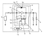
- FIG. 1 is a circuit block diagram of an in-vehicle power supply device 10 according to an embodiment of the present invention.
- FIG. 2 is a schematic diagram of a vehicle 9 on which the in-vehicle power supply device 10 is mounted.
- FIG. 3 shows the output voltage of the in-vehicle power supply device 10.
- the in-vehicle power supply device 10 mounted on the vehicle 9 includes an input terminal 11, a power supply circuit unit 15, an output terminal 16, and a control unit 17.
- the boost converter unit 12 In the power supply circuit unit 15, the boost converter unit 12, the current-carrying auxiliary diode 13 and the switch element 14 are connected in parallel.
- the output terminal 16 is connected to the input terminal 11 via the power supply circuit unit 15.
- the control unit 17 detects the voltage at the output terminal 16. Further, the control unit 17 controls the boost converter unit 12 and the switch element 14.
- the anode 13 a of the current-carrying auxiliary diode 13 is connected to the input terminal 11, and the cathode 13 b of the current-carrying auxiliary diode 13 is connected to the output terminal 16.
- the boost converter unit 12 is connected between the input terminal 11 and the output terminal 16, performs a boost operation to boost the voltage supplied from the input terminal 11, and sends the boosted voltage from the output terminal 16. It is configured to output.
- the energization assist diode 13 is connected in parallel with the boost converter unit 12 between the input terminal 11 and the output terminal 16.
- the switch element 14 is connected between the input terminal 11 and the output terminal 16 in parallel with the boost converter unit 12 and the current-carrying auxiliary diode 13.
- the step-up converter unit 12 includes an inductor 12a, a switching element 12b, a diode 12c, and a smoothing capacitor 12d.
- One end of the inductor 12 a is connected to the input terminal 11.
- the other end of the inductor 12 is connected to the connection point 12e.
- the switching element 12b is connected between the connection point 12e and the ground.
- the anode of the diode 12 c is connected to the connection point 12 e, and the cathode is connected to the output terminal 16.
- the smoothing capacitor 12d is connected between the output terminal 16 and the ground.
- the control unit 17 instructs the switch element 14 to open the switch element 14 at the time t1, and the boost converter unit 12 stops the boost operation of the boost converter unit 12. To instruct.
- the control unit 17 detects the voltage of the output terminal 16 and stores the detected voltage value as the first voltage Vt1. That is, the control unit 17 instructs the switch element 14 and the boost converter unit 12 as described above to detect the voltage output from the output terminal 16 as the first voltage Vt1.
- the control unit 17 After detecting the voltage at the output terminal 16, the control unit 17 instructs the switch element 14 to continuously open the switch element 14 at time t2, and the boost converter unit 12 performs the boost operation.
- the unit 12 is instructed.
- the control unit 17 detects the voltage of the output terminal 16 and stores the detected voltage value as the second voltage Vt2. That is, the control unit 17 detects the voltage output from the output terminal 16 as the second voltage Vt2 by instructing the switch element 14 and the boost converter unit 12 as described above.
- control unit 17 determines the state of the boost converter unit 12, that is, whether the boost converter unit 12 is normal or abnormal, based on the potential difference Vdp that is the difference between the second voltage Vt2 and the first voltage Vt1.
- the control unit 17 compares the potential difference Vdp between the second voltage Vt2 and the first voltage Vt1 with a predetermined threshold value Vth, and the state of the boost converter unit 12, that is, the boost converter unit 12 is normal. Or whether it is abnormal.
- the boost converter unit 12 is normal and operates normally, the forward voltage Vdi is applied between the anode 13a and the cathode 13b of the conduction assist diode 13 when the boost converter unit 12 is not performing the boost operation.
- the potential difference Vdp compared with the threshold value Vth is a value obtained by adding the forward voltage Vdi to the boost width Vsu, which is a potential difference associated with the boost operation of the boost converter unit 12.
- the threshold value Vth can be increased. That is, the state of boost converter unit 12 can be determined based on large threshold value Vth and potential difference Vdp that are not easily affected by noise or the like. Therefore, the control unit 17 can stably determine with high accuracy whether or not the boost converter unit 12 is operating normally.
- the in-vehicle power supply device 10 mounted on the vehicle 9 has an input terminal 11 and an output terminal 16.
- the input terminal 11 is connected to the storage battery 18, and the output terminal 16 is connected to the load 19. That is, the storage battery 18 and the load 19 are connected via the in-vehicle power supply device 10.
- the step-up converter unit 12, the energization assist diode 13, and the switch element 14 are connected in parallel to the input terminal 11.
- the control unit 17 is arranged inside the in-vehicle power supply device 10.
- the control unit 17 is not necessarily limited to the configuration arranged inside the in-vehicle power supply device 10 and may be arranged outside the in-vehicle power supply device 10.
- the in-vehicle power supply device 10 may include a control terminal connected to the control unit 17 disposed outside the in-vehicle power supply device 10 instead of the control unit 17 of the in-vehicle power supply device 10.
- switch element 14 and boost converter unit 12 may be in any state before time t1.
- control start unit 17 When the control start unit 17 receives the determination start signal 17a from the vehicle 9, the control unit 17 instructs the switch element 14 to open the switch element 14 at time t1. Then, the control unit 17 instructs the boost converter unit 12 to stop the boost operation of the boost converter unit 12 at the time point t1 or to continue the stop state of the boost operation of the boost converter unit 12. That is, the control unit 17 instructs not to perform a boosting operation for boosting the input voltage Vin in the boosting converter unit 12. In response to this instruction, the switch element 14 is opened, and the boost converter unit 12 does not perform the boost operation. With this configuration, the power of the storage battery 18 is supplied to the load 19 through the input terminal 11, the energization assist diode 13, and the output terminal 16.
- the forward voltage Vdi is generated in the current-carrying diode 13
- a voltage (Vin ⁇ Vdi) that is lower than the voltage Vin output from the storage battery 18 by the forward voltage Vdi is output from the output terminal 16.
- the control unit 17 detects and stores the voltage (Vin ⁇ Vdi) as the first voltage Vt1.
- the switching element 14 is correctly opened according to an instruction from the control unit 17, and the boosting converter unit 12 correctly performs a boost operation so as not to boost the input voltage Vin according to the instruction from the control unit 17. This is a period P1 from the time point t1 to the time point t2.
- the period when the switch element 14 is opened may start.
- the determination of the state of the boost converter unit 12 in the in-vehicle power supply device 10 is performed when the vehicle 9 is not activated. Therefore, a period in which the boost operation of boost converter unit 12 stops, that is, a period in which boost converter unit 12 is not operating exists when vehicle 9 is not activated.
- the first voltage Vt1 may be stored in the control unit 17 or stored outside the control unit 17. Further, it is desirable that the time point td1 at which the control unit 17 detects the first voltage at the output terminal 16 is delayed by a predetermined time from the time point t1 and not at the same time as the time point t1. If the first voltage Vt1 is detected simultaneously with the time point t1, the first voltage Vt1 may not be accurately detected because the voltage fluctuation instantaneously increases due to a transient phenomenon. However, when the voltage fluctuation due to the transient phenomenon is suppressed, the time point td1 and the time point t1 at which the first voltage Vt1 is detected may be simultaneous.
- the control unit 17 After the control unit 17 detects the first voltage Vt1 of the output terminal 16, or at a time point t2 after storing the first voltage Vt1, the control unit 17 continues the state where the switch element 14 is opened as it is.
- the switch element 14 is instructed, and the boost converter unit 12 instructs the boost converter unit 12 to perform a boost operation for boosting the input voltage Vin to the second voltage Vt2.
- the switch element 14 continues to be open, and the boost converter unit 12 performs a boost operation. With this operation, the power of the storage battery 18 is supplied to the load 19 through the input terminal 11, the boost converter unit 12, and the output terminal 16.
- the second voltage Vt2 boosted by the boost converter unit 12 that is higher than the voltage output from the input terminal 11 through the current-carrying auxiliary diode 13 is supplied to the output terminal 16.
- the switching element 14 continues to be correctly opened according to the instruction from the control unit 17, and the boost converter unit 12 correctly boosts the input voltage Vin according to the instruction from the control unit 17.
- This is a period P2 from time t2 to time t3.
- the control unit 17 detects the voltage of the output terminal 16 as the second voltage Vt2, and further stores the second voltage Vt2.
- the second voltage Vt2 may be stored in the control unit 17 or stored outside the control unit 17. Further, it is desirable that the control unit 17 does not coincide with the time point td2 when the second voltage Vt2 of the output terminal 16 is detected. This is because if the time point td2 and the time point t2 are the same, the instantaneous voltage fluctuation increases due to a transient phenomenon, and thus the second voltage Vt2 may not be detected accurately. However, when the voltage fluctuation due to the transient phenomenon is suppressed, the time point td2 and the time point t2 may be simultaneous.
- the control unit 17 calculates the potential difference Vdp before and after boosting by using the second voltage Vt2 and the first voltage Vt1 stored in advance.
- the potential difference Vdp corresponds to the difference between the first voltage Vt2 and the first voltage Vt1, that is, the potential difference between the first voltage Vt1 and the second voltage Vt2.
- the control unit 17 compares the potential difference Vdp obtained by calculation with a preset threshold value Vth.
- the control unit 17 indicates that the boost converter unit 12 is capable of boosting to a predetermined value, and the boost converter unit 12 is normal and operating normally. Is determined.
- the control unit 17 indicates that the boost converter unit 12 is not sufficiently boosted to a predetermined value, and the boost converter unit 12 is abnormal and not operating normally. Is determined.
- the potential difference Vdp is a value obtained by adding the forward voltage Vdi to the boosted width Vsu, which is the difference obtained by subtracting the input terminal voltage Vin from the second voltage Vt2 by the boost converter unit 12.
- the value of the threshold Vth can be increased by an amount corresponding to the forward voltage Vdi. That is, the values of the potential difference Vdp and the threshold value Vth are less affected by noise existing around the in-vehicle power supply device 10 because the absolute values thereof can be increased. As a result, it is possible to stably determine whether or not the boost converter unit 12 is operating normally, so that the determination accuracy can be improved stably.
- the load 19 is connected to the output terminal 16, but the potential difference Vdp and the threshold value Vth can be compared even when the load 19 is not connected. That is, the boost converter unit 12 can determine the state of the boost converter unit 12 with very small power consumption.
- control unit 17 instructs the boost converter unit 12 to finish the boost operation at a time t3 when the predetermined time has elapsed from the time t2.
- the time point t3 when the boosting operation in the boosting converter unit 12 is finished may be before or after the calculation or determination described above in the control unit 17 is performed.
- the determination start signal 17a may be interlocked with various elements constituting the vehicle 9.
- the vehicle 9 includes a vehicle body 9a, a door 9b provided on the vehicle body 9a, an in-vehicle power supply device 10 provided on the vehicle body 9a, a storage battery 18 provided on the vehicle body 9a, and a load 19 provided on the vehicle body 9a.
- the engine 20 provided in the vehicle body 9a, the brake pedal 21 provided in the vehicle body 9a, the vehicle start switch 22 provided in the vehicle body 9a, and the warning device 23 provided in the vehicle body 9a are included.
- the in-vehicle power supply device 10 boosts the voltage of the storage battery 18 and supplies the voltage to the load 19. It is stabilized.
- the timing at which the stopped engine 20 is restarted is determined based on the timing of operation of the brake pedal 21 by the driver. This operation is the operation of the in-vehicle power supply device 10 when the vehicle 9 is activated.
- the control unit 17 determines the state of the boost converter unit 12 while the vehicle 9 and the engine 20 are not activated. For example, when an engine switch corresponding to the vehicle activation switch 22 is switched from ON to OFF by the driver, the control unit 17 determines the state of the boost converter unit 12. That is, in response to switching of the engine switch corresponding to the vehicle start switch 22 from ON to OFF, the vehicle start switch 22 or a predetermined portion of the vehicle 9 outputs the determination start signal 17 a to the control unit 17. Alternatively, the determination start signal 17 a may be transmitted / received inside the control unit 17.
- control unit 17 determines the state of the boost converter unit 12 in a state where the engine 20 has completely stopped starting. Therefore, since the power consumed by the load 19 is small and limited, the influence of the fluctuation of the load 19 on the fluctuation of the voltage at the output terminal 16 can be reduced. As a result, the control unit 17 can accurately determine the state of the boost converter unit 12 based on the voltage detected at the output terminal 16.
- the control unit 17 may determine the state of the boost converter unit 12. That is, in response to switching of the accessory switch corresponding to the vehicle start switch 22 from ON to OFF, the determination start signal 17 a is issued from the vehicle start switch 22 or a predetermined portion of the vehicle 9 to the control unit 17. Alternatively, the determination start signal 17 a may be transmitted / received inside the control unit 17.
- the determination on the state of the boost converter unit 12 is performed in a state where the engine 20 is completely stopped and power can be supplied only to the load 19 limited by the vehicle power supply device 10,
- the state of the converter unit 12 can be determined. Therefore, the power consumed by the load 19 is smaller and limited than when the engine switch is turned off. That is, the operation of the electrical component such as the car audio that is the load 19 mounted on the vehicle 9 is stopped. Therefore, the influence of the fluctuation of the load 19 on the fluctuation of the output voltage at the output terminal 16 is very small.
- the control unit 17 can accurately determine the state of the boost converter unit 12 based on the voltage detected at the output terminal 16.
- the determination start signal 17a When the determination start signal 17a is issued in response to switching of the accessory switch corresponding to the vehicle start switch 22 from ON to OFF, the timing at which the control unit 17 detects the first voltage Vt1 can be freely set. It is. That is, the determination start signal 17a may be issued immediately after the accessory switch is switched from ON to OFF, or may be issued after a predetermined time from the ON / OFF switch of the accessory switch. In particular, since the determination start signal 17a is issued after a predetermined time has elapsed since the accessory switch was switched from ON to OFF, the power consumed by the load 19 is small and limited, and fluctuations in power are also suppressed.
- the control unit 17 can accurately determine the state of the boost converter unit 12 based on the voltage detected at the output terminal 16.
- the control unit 17 transmits a warning signal to the warning device 23 when it is determined that the boost converter unit 12 is abnormal, and transmits a warning signal to the warning device 23 when it is determined that the boost converter unit 12 is normal. It is preferable not to send.
- the driver may issue a warning signal from the control unit 17 to the warning device 23 at the next timing of starting the vehicle 9 by the vehicle activation switch 22. Therefore, the control part 17 should just memorize
- the determination start signal 17a may be issued to the control unit 17 before the vehicle 9 or the engine 20 is started.
- an operator such as a driver or a passenger releases the driver of the door lock device 9c provided on the door 9b, or a remote control key (FIG.
- the determination start signal 17a may be sent to the control unit 17 when the door lock device 9c is released by, for example, not shown. Alternatively, at that time, the determination start signal 17a may be transmitted and received within the control unit 17.
- the control unit 17 can more accurately determine the state of the boost converter unit 12 based on the voltage detected at the output terminal 16.
- the control unit 17 transmits a warning signal to the warning device 23 when it is determined that the boost converter unit 12 is abnormal, and transmits a warning signal to the warning device 23 when it is determined that the boost converter unit 12 is normal. Do not send.
- a warning signal may be issued from the control unit 17 to the warning device 23 at the timing when the driver starts the vehicle 9 with the vehicle start switch 22.
- the switch element 14 may be composed of a relay switch or a field effect transistor (FET) switch.
- FIG. 4 is a block diagram of another in-vehicle power supply device 10a according to the embodiment.
- the in-vehicle power supply device 10 a includes an FET switch 51 made of an FET constituting the switch element 14. With this configuration, the in-vehicle power supply device 10a can be made small and light.
- the FET switch 51 includes a switch unit 51a that is controlled by the control unit 17 to open and close, and a parasitic diode 51b connected in parallel to the switch unit 51a.
- the switch unit 51a and the parasitic diode 51b function as the switch element 14 and the conduction auxiliary diode 13 of the in-vehicle power supply device 10 shown in FIG. With this configuration, the circuit configuration of the power supply circuit unit 15 is further simplified. As a result, the connection reliability of the in-vehicle power supply device 10a is improved.
- the FET switch 51 may be either a P-type FET or an N-type FET.
- the on-vehicle power supply device of the present invention has an effect of stabilizing the accuracy of determination as to whether or not the boost converter unit is operating normally, and is useful in various vehicles.
Landscapes
- Engineering & Computer Science (AREA)
- Power Engineering (AREA)
- Mechanical Engineering (AREA)
- Transportation (AREA)
- Life Sciences & Earth Sciences (AREA)
- Sustainable Development (AREA)
- Sustainable Energy (AREA)
- Human Computer Interaction (AREA)
- Dc-Dc Converters (AREA)
Abstract
Description
9a 車体
9b ドア
9c ドアロック装置
10,10a 車載用電源装置
11 入力端子
12 昇圧コンバータ部
13 通電補助ダイオード
14 スイッチ素子
15 電源回路部
16 出力端子
17 制御部
17a 判定始動信号
18 蓄電池
19 負荷
20 エンジン
21 ブレーキペダル
22 車両起動スイッチ
23 警告装置
51 FETスイッチ
51a スイッチ部
51b 寄生ダイオード
Claims (5)
- 入力端子と、
出力端子と、
前記入力端子と前記出力端子との間に接続されて、前記入力端子から供給された電圧を昇圧する昇圧動作を行い、前記昇圧された電圧を前記出力端子から出力するよう構成された昇圧コンバータ部と、
前記入力端子と前記出力端子との間で前記昇圧コンバータ部と並列に接続された通電補助ダイオードと、
前記入力端子と前記出力端子との間で前記昇圧コンバータ部と通電補助ダイオードと並列に接続されたスイッチ素子と、
を有する電源回路部と、
前記昇圧コンバータ部および前記スイッチ素子を制御する制御部と、
を備え、
前記制御部は、
前記スイッチ素子の開放と前記昇圧コンバータ部の動作の停止を前記スイッチ素子と前記昇圧コンバータ部とに指示することにより前記出力端子から出力される電圧を第1電圧として検出し、
前記出力端子の前記第1の電圧を検出した後に、前記スイッチ素子を継続して開放してかつ前記昇圧コンバータ部が前記昇圧動作を行うように前記昇圧コンバータ部に指示することにより前記出力端子から出力される電圧を第2電圧として検出し、
前記第2電圧と前記第1電圧との差に基づいて前記昇圧コンバータ部が正常であるか異常であるかを判定する、
ように構成された、車載用電源装置。 - 前記スイッチ素子は電界効果トランジスタ(FET)スイッチにより構成されている、請求項1に記載の車載用電源装置。
- 前記FETスイッチは、
前記スイッチ素子として動作するスイッチ部と、
前記スイッチ部と並列に接続されており、前記補助通電ダイオードとして動作する寄生ダイオードと、
を有する、請求項2に記載の車載用電源装置。 - 請求項1に記載の車載用電源装置と、
車体と、
前記車体に設けられたエンジンと、
前記車体に設けられてかつ前記車載用電源装置の前記入力端子に接続された蓄電池と、
前記車体に設けられた車両起動スイッチと、
前記車体に設けられた警告装置と、
を備え、
前記制御部は、
前記昇圧コンバータ部が異常であると判定した場合に前記警告装置に警告信号を発信し、
前記昇圧コンバータ部が正常であると判定した場合に前記警告装置に前記警告信号を発信しない、
ように構成された、車両。 - 車体と、
前記車体に設けられたエンジンと、
前記車体に設けられた蓄電池と、
前記車体に設けられた車両起動スイッチと、
前記車体に設けられたドアと、
前記ドアに設けられたドアロック装置と、
前記蓄電池に接続された入力端子と、
出力端子と、
前記入力端子と前記出力端子との間に接続されて、前記入力端子から供給された電圧を昇圧する昇圧動作を行い、前記昇圧された電圧を前記出力端子から出力するよう構成された昇圧コンバータ部と、
前記入力端子と前記出力端子との間で前記昇圧コンバータ部と並列に接続された通電補助ダイオードと、
前記入力端子と前記出力端子との間で前記昇圧コンバータ部と通電補助ダイオードと並列に接続されたスイッチ素子と、
を備えた車載用電源装置と、
前記車体に設けられた警告装置と、
を備え、
前記制御部は、
前記車両起動スイッチがOFFで前記ドアロック装置が解除へと切り替えられたことを検知したことに応じて、前記スイッチ素子を開放するように前記スイッチ素子に指示するとともに、前記昇圧コンバータ部に動作を停止するように前記昇圧コンバータ部に指示することによって前記出力端子から出力される電圧を第1電圧として検出し、
前記出力端子の前記電圧を検出した後に、前記スイッチ素子を継続して開放するように前記スイッチ素子に指示するとともに、前記昇圧コンバータ部が昇圧動作を行うように前記昇圧コンバータ部に指示することにより前記出力端子から出力された電圧を第2電圧として検出し、
前記制御部は、前記第2電圧と前記第1電圧との差に基づいて前記昇圧コンバータ部が正常であるか異常であるかを判定し、
前記昇圧コンバータ部が異常であると判定した場合に、前記警告装置に警告信号を発信し、
前記昇圧コンバータ部が正常であると判定した場合に、前記警告装置に前記警告信号を発信しない、
ように構成された、車両。
Priority Applications (4)
| Application Number | Priority Date | Filing Date | Title |
|---|---|---|---|
| US15/518,669 US10118575B2 (en) | 2014-11-13 | 2015-09-24 | In-vehicle power supply device and vehicle having in-vehicle power supply device mounted therein |
| CN201580050613.9A CN106716802B (zh) | 2014-11-13 | 2015-09-24 | 车载用电源装置以及搭载有车载用电源装置的车辆 |
| JP2016558857A JP6535887B2 (ja) | 2014-11-13 | 2015-09-24 | 車載用電源装置およびそれを搭載した車両 |
| EP15859314.5A EP3220524B1 (en) | 2014-11-13 | 2015-09-24 | In-vehicle power supply device and vehicle having in-vehicle power supply device mounted therein |
Applications Claiming Priority (2)
| Application Number | Priority Date | Filing Date | Title |
|---|---|---|---|
| JP2014230314 | 2014-11-13 | ||
| JP2014-230314 | 2014-11-13 |
Publications (1)
| Publication Number | Publication Date |
|---|---|
| WO2016075856A1 true WO2016075856A1 (ja) | 2016-05-19 |
Family
ID=55953963
Family Applications (1)
| Application Number | Title | Priority Date | Filing Date |
|---|---|---|---|
| PCT/JP2015/004837 WO2016075856A1 (ja) | 2014-11-13 | 2015-09-24 | 車載用電源装置およびそれを搭載した車両 |
Country Status (5)
| Country | Link |
|---|---|
| US (1) | US10118575B2 (ja) |
| EP (1) | EP3220524B1 (ja) |
| JP (1) | JP6535887B2 (ja) |
| CN (1) | CN106716802B (ja) |
| WO (1) | WO2016075856A1 (ja) |
Families Citing this family (7)
| Publication number | Priority date | Publication date | Assignee | Title |
|---|---|---|---|---|
| EP3179620B1 (en) * | 2014-08-07 | 2019-09-04 | Panasonic Intellectual Property Management Co., Ltd. | In-vehicle power supply device and vehicle mounted with same |
| JP6691665B2 (ja) * | 2016-08-05 | 2020-05-13 | 株式会社Gsユアサ | 蓄電装置、蓄電装置の制御方法、車両 |
| DE112018006864T5 (de) * | 2018-01-16 | 2020-10-15 | Mitsubishi Electric Corporation | Signalsteuervorrichtung und abnormalitätserfassungsverfahren |
| JP6787959B2 (ja) * | 2018-09-20 | 2020-11-18 | 株式会社Subaru | 給電コネクタ切離し装置 |
| JP2020045070A (ja) * | 2018-09-21 | 2020-03-26 | 日立オートモティブシステムズ株式会社 | 車両用作動機構の制御装置 |
| CN109444518A (zh) * | 2018-10-26 | 2019-03-08 | 中国人民解放军空军勤务学院 | 一种电源车升压转换快速检测系统、检测方法及检测设备 |
| JP7200747B2 (ja) * | 2019-02-26 | 2023-01-10 | 株式会社デンソー | 電源装置 |
Citations (5)
| Publication number | Priority date | Publication date | Assignee | Title |
|---|---|---|---|---|
| JPH06311733A (ja) * | 1993-04-21 | 1994-11-04 | Fujitsu Ten Ltd | 昇圧回路の異常検出装置 |
| JP2008029126A (ja) * | 2006-07-21 | 2008-02-07 | Fujitsu Ten Ltd | 昇圧回路、モータ駆動回路及び電動パワーステアリング制御装置 |
| JP2011095915A (ja) * | 2009-10-28 | 2011-05-12 | Omron Corp | 異常判定装置、パワーコンディショナ、異常判定方法、及びプログラム |
| JP2013074741A (ja) * | 2011-09-28 | 2013-04-22 | Toyota Industries Corp | 電源回路 |
| JP2014156210A (ja) * | 2013-02-18 | 2014-08-28 | Panasonic Corp | 車載用電源装置 |
Family Cites Families (19)
| Publication number | Priority date | Publication date | Assignee | Title |
|---|---|---|---|---|
| JPS515518A (ja) * | 1974-07-05 | 1976-01-17 | Hitachi Ltd | |
| US5321348A (en) * | 1991-03-08 | 1994-06-14 | Vlt Corporation | Boost switching power conversion |
| TW472426B (en) * | 1998-10-06 | 2002-01-11 | Hitachi Ltd | Battery apparatus and control system therefor |
| JP2003088100A (ja) * | 2001-09-13 | 2003-03-20 | Tdk Corp | スイッチング電源装置 |
| JP4149415B2 (ja) * | 2004-05-31 | 2008-09-10 | 株式会社ケーヒン | 昇圧電源制御装置および昇圧電源制御装置の故障部位特定判定方法 |
| JP4162645B2 (ja) * | 2004-10-05 | 2008-10-08 | 三洋電機株式会社 | 車両用の電源装置 |
| JP4923831B2 (ja) * | 2006-08-08 | 2012-04-25 | パナソニック株式会社 | 電源装置 |
| JP4715766B2 (ja) * | 2007-02-13 | 2011-07-06 | トヨタ自動車株式会社 | 昇圧システムの故障診断装置、昇圧回路の制御装置および車両 |
| JP4659873B2 (ja) * | 2008-11-11 | 2011-03-30 | トヨタ自動車株式会社 | 車両およびその制御方法並びに駆動装置 |
| CN102414043B (zh) * | 2009-04-23 | 2014-03-19 | 丰田自动车株式会社 | 电动车辆的电源系统及其控制方法 |
| DE102009028502A1 (de) * | 2009-08-13 | 2011-02-17 | Robert Bosch Gmbh | Verfahren zum Überwachen eines Antriebszustands eines Elektromotors |
| JP5606857B2 (ja) * | 2010-09-30 | 2014-10-15 | ラピスセミコンダクタ株式会社 | 組電池システム、昇圧手段の異常診断方法、電池監視ic、半導体装置、及び半導体装置の昇圧手段の異常診断方法 |
| JP5718067B2 (ja) * | 2011-01-17 | 2015-05-13 | ラピスセミコンダクタ株式会社 | 昇圧システム、診断方法、及び診断プログラム |
| JP5802502B2 (ja) * | 2011-09-27 | 2015-10-28 | 新電元工業株式会社 | 故障検出装置および方法 |
| JP5929516B2 (ja) * | 2012-05-28 | 2016-06-08 | 株式会社豊田自動織機 | 車両用の電源回路 |
| JP5861624B2 (ja) * | 2012-12-05 | 2016-02-16 | 株式会社豊田自動織機 | 電源回路 |
| US20140203786A1 (en) * | 2013-01-22 | 2014-07-24 | Kabushiki Kaisha Toshiba | Power supply apparatus and power supply control apparatus |
| JP2014166033A (ja) * | 2013-02-25 | 2014-09-08 | Toyota Motor Corp | 電源装置 |
| JP5971265B2 (ja) * | 2014-01-20 | 2016-08-17 | トヨタ自動車株式会社 | 昇圧コンバータの制御装置 |
-
2015
- 2015-09-24 WO PCT/JP2015/004837 patent/WO2016075856A1/ja active Application Filing
- 2015-09-24 US US15/518,669 patent/US10118575B2/en active Active
- 2015-09-24 JP JP2016558857A patent/JP6535887B2/ja active Active
- 2015-09-24 CN CN201580050613.9A patent/CN106716802B/zh active Active
- 2015-09-24 EP EP15859314.5A patent/EP3220524B1/en active Active
Patent Citations (5)
| Publication number | Priority date | Publication date | Assignee | Title |
|---|---|---|---|---|
| JPH06311733A (ja) * | 1993-04-21 | 1994-11-04 | Fujitsu Ten Ltd | 昇圧回路の異常検出装置 |
| JP2008029126A (ja) * | 2006-07-21 | 2008-02-07 | Fujitsu Ten Ltd | 昇圧回路、モータ駆動回路及び電動パワーステアリング制御装置 |
| JP2011095915A (ja) * | 2009-10-28 | 2011-05-12 | Omron Corp | 異常判定装置、パワーコンディショナ、異常判定方法、及びプログラム |
| JP2013074741A (ja) * | 2011-09-28 | 2013-04-22 | Toyota Industries Corp | 電源回路 |
| JP2014156210A (ja) * | 2013-02-18 | 2014-08-28 | Panasonic Corp | 車載用電源装置 |
Non-Patent Citations (1)
| Title |
|---|
| See also references of EP3220524A4 * |
Also Published As
| Publication number | Publication date |
|---|---|
| CN106716802A (zh) | 2017-05-24 |
| JPWO2016075856A1 (ja) | 2017-08-24 |
| CN106716802B (zh) | 2019-01-15 |
| EP3220524A1 (en) | 2017-09-20 |
| EP3220524A4 (en) | 2018-03-21 |
| EP3220524B1 (en) | 2019-01-02 |
| US20170225636A1 (en) | 2017-08-10 |
| JP6535887B2 (ja) | 2019-07-03 |
| US10118575B2 (en) | 2018-11-06 |
Similar Documents
| Publication | Publication Date | Title |
|---|---|---|
| WO2016075856A1 (ja) | 車載用電源装置およびそれを搭載した車両 | |
| WO2018070231A1 (ja) | 車載用のバックアップ装置 | |
| JP6572447B2 (ja) | 車載用電源装置およびそれを搭載した車両 | |
| US7639519B2 (en) | Switching booster power circuit | |
| US9499063B2 (en) | Power-supply device | |
| US20150112578A1 (en) | Vehicular power-supply circuit | |
| JP6528129B2 (ja) | バックアップ電源装置およびバックアップ電源装置を用いた車両 | |
| CN105383420B (zh) | 利用瞬间操作提供升压电压 | |
| JP6751512B2 (ja) | 車載用電源装置 | |
| KR102125893B1 (ko) | 보조 에너지 저장 장치를 이용한 방전 차량 점프 스타트 시스템 | |
| CN112218788A (zh) | 车载用的电源控制装置和车载用电源系统 | |
| JP6551089B2 (ja) | 車載用電源装置 | |
| US10714972B2 (en) | Power supply control apparatus | |
| JP6757887B2 (ja) | 車載用非常電源装置 | |
| JP2015035937A (ja) | Dc−dcコンバータ | |
| JP6209729B2 (ja) | 車載用電源装置 | |
| JP2017065583A (ja) | 車載用電源装置 | |
| JP6147317B2 (ja) | 給電制御装置 | |
| JP6024648B2 (ja) | 補助電源装置 | |
| JP2013241036A (ja) | 車両用電源制御回路 | |
| JP2008072837A (ja) | 電源装置 | |
| JP2015107731A (ja) | 電源装置 | |
| JP2014100017A (ja) | 充放電制御回路、車両用電源装置及び故障判定方法 |
Legal Events
| Date | Code | Title | Description |
|---|---|---|---|
| 121 | Ep: the epo has been informed by wipo that ep was designated in this application |
Ref document number: 15859314 Country of ref document: EP Kind code of ref document: A1 |
|
| REEP | Request for entry into the european phase |
Ref document number: 2015859314 Country of ref document: EP |
|
| WWE | Wipo information: entry into national phase |
Ref document number: 2015859314 Country of ref document: EP |
|
| ENP | Entry into the national phase |
Ref document number: 2016558857 Country of ref document: JP Kind code of ref document: A |
|
| WWE | Wipo information: entry into national phase |
Ref document number: 15518669 Country of ref document: US |
|
| NENP | Non-entry into the national phase |
Ref country code: DE |