WO2016059858A1 - 圧縮機用スクロールの製造方法、製造装置、圧縮機用スクロールおよびスクロール圧縮機 - Google Patents
圧縮機用スクロールの製造方法、製造装置、圧縮機用スクロールおよびスクロール圧縮機 Download PDFInfo
- Publication number
- WO2016059858A1 WO2016059858A1 PCT/JP2015/072426 JP2015072426W WO2016059858A1 WO 2016059858 A1 WO2016059858 A1 WO 2016059858A1 JP 2015072426 W JP2015072426 W JP 2015072426W WO 2016059858 A1 WO2016059858 A1 WO 2016059858A1
- Authority
- WO
- WIPO (PCT)
- Prior art keywords
- scroll
- compressor
- wall
- manufacturing
- end plate
- Prior art date
- Legal status (The legal status is an assumption and is not a legal conclusion. Google has not performed a legal analysis and makes no representation as to the accuracy of the status listed.)
- Ceased
Links
Images


Classifications
-
- B—PERFORMING OPERATIONS; TRANSPORTING
- B24—GRINDING; POLISHING
- B24C—ABRASIVE OR RELATED BLASTING WITH PARTICULATE MATERIAL
- B24C3/00—Abrasive blasting machines or devices; Plants
- B24C3/32—Abrasive blasting machines or devices; Plants designed for abrasive blasting of particular work, e.g. the internal surfaces of cylinder blocks
-
- B—PERFORMING OPERATIONS; TRANSPORTING
- B24—GRINDING; POLISHING
- B24C—ABRASIVE OR RELATED BLASTING WITH PARTICULATE MATERIAL
- B24C1/00—Methods for use of abrasive blasting for producing particular effects; Use of auxiliary equipment in connection with such methods
- B24C1/10—Methods for use of abrasive blasting for producing particular effects; Use of auxiliary equipment in connection with such methods for compacting surfaces, e.g. shot-peening
-
- B—PERFORMING OPERATIONS; TRANSPORTING
- B24—GRINDING; POLISHING
- B24C—ABRASIVE OR RELATED BLASTING WITH PARTICULATE MATERIAL
- B24C11/00—Selection of abrasive materials or additives for abrasive blasts
- B24C11/005—Selection of abrasive materials or additives for abrasive blasts of additives, e.g. anti-corrosive or disinfecting agents in solid, liquid or gaseous form
-
- C—CHEMISTRY; METALLURGY
- C21—METALLURGY OF IRON
- C21D—MODIFYING THE PHYSICAL STRUCTURE OF FERROUS METALS; GENERAL DEVICES FOR HEAT TREATMENT OF FERROUS OR NON-FERROUS METALS OR ALLOYS; MAKING METAL MALLEABLE, e.g. BY DECARBURISATION OR TEMPERING
- C21D7/00—Modifying the physical properties of iron or steel by deformation
- C21D7/02—Modifying the physical properties of iron or steel by deformation by cold working
- C21D7/04—Modifying the physical properties of iron or steel by deformation by cold working of the surface
- C21D7/06—Modifying the physical properties of iron or steel by deformation by cold working of the surface by shot-peening or the like
-
- F—MECHANICAL ENGINEERING; LIGHTING; HEATING; WEAPONS; BLASTING
- F04—POSITIVE - DISPLACEMENT MACHINES FOR LIQUIDS; PUMPS FOR LIQUIDS OR ELASTIC FLUIDS
- F04C—ROTARY-PISTON, OR OSCILLATING-PISTON, POSITIVE-DISPLACEMENT MACHINES FOR LIQUIDS; ROTARY-PISTON, OR OSCILLATING-PISTON, POSITIVE-DISPLACEMENT PUMPS
- F04C18/00—Rotary-piston pumps specially adapted for elastic fluids
- F04C18/02—Rotary-piston pumps specially adapted for elastic fluids of arcuate-engagement type, i.e. with circular translatory movement of co-operating members, each member having the same number of teeth or tooth-equivalents
- F04C18/0207—Rotary-piston pumps specially adapted for elastic fluids of arcuate-engagement type, i.e. with circular translatory movement of co-operating members, each member having the same number of teeth or tooth-equivalents both members having co-operating elements in spiral form
- F04C18/0215—Rotary-piston pumps specially adapted for elastic fluids of arcuate-engagement type, i.e. with circular translatory movement of co-operating members, each member having the same number of teeth or tooth-equivalents both members having co-operating elements in spiral form where only one member is moving
-
- F—MECHANICAL ENGINEERING; LIGHTING; HEATING; WEAPONS; BLASTING
- F04—POSITIVE - DISPLACEMENT MACHINES FOR LIQUIDS; PUMPS FOR LIQUIDS OR ELASTIC FLUIDS
- F04C—ROTARY-PISTON, OR OSCILLATING-PISTON, POSITIVE-DISPLACEMENT MACHINES FOR LIQUIDS; ROTARY-PISTON, OR OSCILLATING-PISTON, POSITIVE-DISPLACEMENT PUMPS
- F04C18/00—Rotary-piston pumps specially adapted for elastic fluids
- F04C18/02—Rotary-piston pumps specially adapted for elastic fluids of arcuate-engagement type, i.e. with circular translatory movement of co-operating members, each member having the same number of teeth or tooth-equivalents
- F04C18/0207—Rotary-piston pumps specially adapted for elastic fluids of arcuate-engagement type, i.e. with circular translatory movement of co-operating members, each member having the same number of teeth or tooth-equivalents both members having co-operating elements in spiral form
- F04C18/0246—Details concerning the involute wraps or their base, e.g. geometry
- F04C18/0269—Details concerning the involute wraps
- F04C18/0276—Different wall heights
-
- F—MECHANICAL ENGINEERING; LIGHTING; HEATING; WEAPONS; BLASTING
- F04—POSITIVE - DISPLACEMENT MACHINES FOR LIQUIDS; PUMPS FOR LIQUIDS OR ELASTIC FLUIDS
- F04C—ROTARY-PISTON, OR OSCILLATING-PISTON, POSITIVE-DISPLACEMENT MACHINES FOR LIQUIDS; ROTARY-PISTON, OR OSCILLATING-PISTON, POSITIVE-DISPLACEMENT PUMPS
- F04C2230/00—Manufacture
- F04C2230/90—Improving properties of machine parts
- F04C2230/92—Surface treatment
Definitions
- the present invention relates to a method of manufacturing a scroll used in a compressor, a manufacturing apparatus, a scroll for a compressor, and a scroll compressor.
- a scroll compressor has a fixed scroll in which a spiral wall body is erected on one side surface of an end plate, and a spiral wall body having substantially the same shape as the fixed scroll wall body on one side surface of the end plate. And an upright orbiting scroll. And one side of each end plate of a fixed scroll and a turning scroll is faced, and it arrange
- JP 2009-74540 A Japanese Patent No. 3162104
- Compressor scrolls are prone to fatigue cracks due to stress concentration during operation at the corners of the joint between the end plate and the wall. Therefore, it is desirable to measure the improvement in fatigue strength by applying a compressive residual stress to the desired location where cracks due to fatigue are prominent.
- As a means for applying the residual stress there is peening and the like.
- peening there is peening and the like.
- cavitation bubbles generated by a water jet in a shot peening are likely to reach a narrow part such as the desired part, so that application to scrolling is more suitable than shot peening.
- the scroll has a shape in which a wall body is erected on the end plate, and is not a plate shape like the test piece shown in Patent Document 2,
- the present invention solves the above-described problems, and a compressor scroll manufacturing method, a manufacturing apparatus, and a compressor scroll in which cracks are prevented from occurring, which can cause cavitation bubbles to collide with a desired portion of the scroll as appropriate. And to provide a scroll compressor.
- a compressor scroll manufacturing method includes a first scroll having a spiral first wall provided on one side surface of a first end plate, and a second end plate.
- a spiral second wall is provided on one side surface, and the second wall is engaged with the first wall of the first scroll and is supported so as to be capable of revolving while being prevented from rotating.
- a step portion in which the height of the one side surface of each of the end plates is increased on the center side of the vortex along the wall body and is lowered on the outer end side, and each of the wall bodies A method of manufacturing a scroll for a compressor in which a height is lowered at a center portion side of a vortex and is increased at an outer end side to form a stepped portion that engages with the step portion of each scroll.
- the cavitation bubbles formed by jetting water jets are In the state where the center of the cavitation bubble is separated from the spiral center of the wall body in the end plate, the step portion is formed on the outer peripheral portion of the cavitation bubble. And a water jet peening process for positioning the stepped portion.
- the stepped portion and the stepped portion are positioned on the outer peripheral portion of the range of the cavitation bubble in a state where the center of the cavitation bubble is separated from the spiral center of the wall body in the end plate. Then, the position of the center of the cavitation bubble reaches a corner where the wall body joins the stepped portion and the stepped portion in the spiral passage by the wall body, and becomes a linear position, and the flow of the liquid flow containing the cavitation bubble Since it is not obstructed by the wall, cavitation bubbles can collide with the corners. That is, the cavitation bubbles can be appropriately collided with a desired portion of the scroll, and a compressive residual stress can be generated at the desired portion, thereby preventing the occurrence of cracks.
- the water jet peening step includes the position of the cavitation bubble and the scroll, and is a virtual line that connects the stepped portion and the stepped portion with a straight line.
- the cavitation bubbles and the scroll are relatively moved so as to intersect each other.
- cavitation bubbles can be appropriately collided with a desired portion (corner) of the scroll, compressive residual stress can be generated at the desired portion, and cracking can be prevented. it can.
- the water jet peening process may stop the relative movement of the cavitation bubble and the scroll for a predetermined time at the position of the cavitation bubble and the scroll.
- cavitation bubbles can sufficiently collide with a desired portion (corner) of the scroll, and compressive residual stress is generated at the desired portion, thereby preventing the occurrence of cracks. Can do.
- the water jet peening process is performed before the surface treatment is performed on the scroll.
- the water jet peening process is performed before the surface treatment is applied to the scroll, thereby assisting the generation of compressive residual stress due to the collision of cavitation bubbles and preventing the generation of cracks.
- the effect to do can be acquired notably.
- a cleaning liquid is mixed in water that generates the cavitation bubbles.
- the scroll can be cleaned with the cleaning liquid simultaneously with the water jet peening process.
- a compressor scroll manufacturing apparatus includes a first scroll having a spiral first wall provided on one side surface of a first end plate, and a second end plate.
- a spiral second wall is provided on one side surface, and the second wall is engaged with the first wall of the first scroll and is supported so as to be capable of revolving while being prevented from rotating.
- a step portion in which the height of the one side surface of each of the end plates is increased on the center side of the vortex along the wall body and is lowered on the outer end side, and each of the wall bodies An apparatus for manufacturing a scroll for a compressor, in which a height is lowered at a center portion side of a vortex and is increased at an outer end side to form a stepped portion that engages with each step portion of each scroll, A container that is filled with, a positioning means that positions and arranges the scroll in the container, Water jet spraying means having nozzles that are disposed in the water in the container and spray the water jet toward the scroll, and the cavitation bubbles generated in the water of the container by the water jet of the water jet spraying means, The outer periphery of the cavitation bubble is injected toward the one side surface of the scroll positioned by the positioning means, and the center of the cavitation bubble is separated from the spiral center of the wall body in the end plate.
- the step portion and the stepped portion are positioned in the portion.
- the water jet peening process in the compressor scroll manufacturing method described above can be performed.
- the positioning means includes a fixing mechanism that engages with the end plate of the scroll to fix the scroll.
- the scroll is held by the fixing mechanism, so that the scroll is held when the cavitation bubbles collide with the scroll, and the cavitation bubbles are caused to collide appropriately at a desired location (corner). It is possible to generate a compressive residual stress at the desired location and prevent the occurrence of cracks.
- the positioning means includes the position of the cavitation bubble and the scroll, and intersects an imaginary line that connects the stepped portion and the stepped portion with a straight line. As described above, it has a moving mechanism for moving the scroll.
- cavitation bubbles can be appropriately collided with a desired portion (corner) of the scroll, and compressive residual stress can be generated at the desired portion, thereby preventing the occurrence of cracks. it can.
- the moving mechanism has a plurality of the fixing mechanisms to move the plurality of scrolls.
- cavitation bubbles can be made to collide with a desired portion (corner) of a plurality of scrolls in order.
- the water jet peening process in the compressor scroll manufacturing method described above can be carried out efficiently.
- the water jet injection means has a turning mechanism for turning the nozzle so that the cavitation bubbles turn with respect to the scroll.
- the cavitation bubbles directly collide with a desired portion (corner portion) which is an inner corner portion between the end plate and the wall body, the cavitation bubbles are sufficiently applied to the desired portion of the scroll. It can be made to collide.
- the compressor scroll according to the present invention is produced using the above-described compressor scroll manufacturing apparatus.
- the occurrence of cracks can be prevented and the occurrence of failures based on the cracks can be reduced.
- the scroll compressor according to the present invention is characterized in that the above-described compressor scroll is applied.
- the occurrence of cracks in the scroll can be prevented, and the occurrence of failures based on the cracks can be reduced.
- cavitation bubbles can be collided with a desired portion of the scroll as appropriate.
- FIG. 1 is a cross-sectional view showing an example of a scroll compressor according to an embodiment of the present invention.
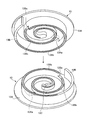
- FIG. 2 is a perspective view of the fixed scroll and the orbiting scroll according to the embodiment of the present invention.
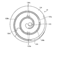
- FIG. 3 is a front view of the fixed scroll according to the embodiment of the present invention.
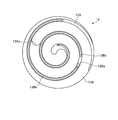
- FIG. 4 is a front view of the orbiting scroll according to the embodiment of the present invention.
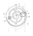
- FIG. 5 is a schematic view showing a method for manufacturing a compressor scroll according to an embodiment of the present invention.
- FIG. 6 is a schematic side view showing the compressor scroll manufacturing apparatus according to the embodiment of the present invention.
- FIG. 1 is a cross-sectional view showing an example of a scroll compressor according to the present embodiment
- FIG. 2 is a perspective view of a fixed scroll and a turning scroll according to the present embodiment
- FIG. 3 is a front view of the fixed scroll according to the present embodiment
- 4 and 4 are front views of the orbiting scroll according to the present embodiment.
- a scroll compressor 10 shown in FIG. 1 is mainly used for compressing a refrigerant of a vehicle air conditioner.
- a scroll compression mechanism including a fixed scroll 12 as a first scroll and a turning scroll 13 as a second scroll is disposed inside a housing 11.
- the housing 11 includes a housing body 11A and a lid body 11B.
- the housing main body 11A has a hollow shape in which a cylindrical large-diameter portion 11Aa and a small-diameter portion 11Ab are integrally formed.
- the large-diameter portion 11Aa side of the housing main body 11A is fixed and closed by a plurality of bolts 20 in a state where the bowl-shaped lid body 11B is fitted to the opening end portion thereof.
- the drive shaft 14 is inserted into the small diameter portion 11Ab side of the housing main body 11A, and the space between the drive shaft 14 and the shaft 11L is sealed. In this way, the housing 11 is configured as a sealed container that wraps the entire scroll compression mechanism.
- the fixed scroll 12 includes an end plate (disk) 12A having a disk shape, and a wall body (lap) 12B formed in a spiral shape standing on one side surface of the end plate 12A, have.
- the fixed scroll 12 is formed on one side of the end plate 12A where the wall body 12B is erected, and is high on the center side along the direction of the vortex of the wall body 12B and low on the outer end side.
- a stepped portion 12Aa is formed so as to be.
- the fixed scroll 12 is formed with a stepped portion 12Ba so as to be lower at the center portion side of the vortex and higher at the outer end side in the wall body 12B.
- the fixed scroll 12 has a groove formed at the edge of the wall body 12B, and a chip seal 12Bb is provided in the groove.
- the fixed scroll 12 is formed with a bypass hole 12Ab in the end plate 12A for preventing over-compression in a compression chamber S1 described later.
- the orbiting scroll 13 has a disk-shaped end plate (disk) 13A and a wall formed in a spiral shape on one side of the end plate 13A, as with the fixed scroll 12. And a body (wrap) 13B.
- the orbiting scroll 13 is provided on one side surface of the end plate 13 ⁇ / b> A where the wall body 13 ⁇ / b> B is erected on the center side along the direction of the vortex of the wall body 13 ⁇ / b> B.
- the step portion 13Aa is formed so as to be higher and lower on the outer terminal side.
- the orbiting scroll 13 is formed with a stepped portion 13Ba so as to be low on the center side of the vortex in the wall body 13B and high on the outer end side.
- the orbiting scroll 13 has a groove formed at the edge of the wall body 13B, and a chip seal 13Bb is provided in the groove.
- the fixed scroll 12 and the orbiting scroll 13 are disposed in the large-diameter portion 11Aa of the housing main body 11A and face one side surfaces of the end plates 12A and 13A so as to face the wall bodies 12B and 13B.
- the compression chamber S1 is formed in a space defined by the end plates 12A, 13A and the wall bodies 12B, 13B in a state where the tip contacts one side surface of the end plates 12A, 13A. Is formed.
- the fixed scroll 12 and the orbiting scroll 13 are engaged with each other with the stepped portions 12Aa and 13Aa and the stepped portions 12Ba and 13Ba in a combined state.
- a suction chamber S3 that communicates with the compression chamber S1 is formed in the outer periphery of the housing main body 11A in which the wall bodies 12B and 13B of the fixed scroll 12 and the orbiting scroll 13 are combined.
- the housing body 11A is formed with a suction port 11Ac for sucking refrigerant gas, and the suction port 11Ac opens into the suction chamber S3.
- the fixed scroll 12 is attached to the lid 11B by a plurality of bolts 21 in a state where the outer peripheral portion of the other side surface of the end plate 12A is in close contact with and fitted to the inner peripheral surface of the lid 11B.
- the discharge chamber S ⁇ b> 2 which is the space between the lid 11 ⁇ / b> B of the housing 11, is defined on the other side of the end plate 12 ⁇ / b> A of the fixed scroll 12.
- the fixed scroll 12 is provided with a discharge port 12 ⁇ / b> C formed so as to penetrate the compression chamber S ⁇ b> 1 and the discharge chamber S ⁇ b> 2 at a position that becomes the spiral center of the wall body 12 ⁇ / b> B in the end plate 12 ⁇ / b> A. Further, the fixed scroll 12 is provided with a discharge valve 12D formed by a leaf spring so that the discharge port 12C is opened only when a pressure of a predetermined magnitude or more is applied to the end plate 12A.
- the orbiting scroll 13 is a shaft which is the extending direction of the drive shaft 14 by the other side surface of the end plate 13A coming into contact with the wall surface 11Ad which is a boundary between the large diameter portion 11Aa and the small diameter portion 11Ab in the housing main body 11A. Movement in the direction is restricted.
- the drive shaft 14 is inserted through the small diameter portion 11Ab of the housing main body 11A.
- the drive shaft 14 has a small diameter portion 11 ⁇ / b> Ab, one end portion 14 ⁇ / b> A is supported by a bearing 22, and a large-diameter disk portion 14 ⁇ / b> B formed at the center portion is supported by a bearing 23, so Is provided.
- an eccentric shaft 14C that is eccentric with respect to the rotation center of the drive shaft 14 is provided integrally with the disk portion 14B.
- the eccentric shaft 14 ⁇ / b> C rotates as the drive shaft 14 rotates.
- the eccentric bush 14C has a balance bush 24 fitted to the outer periphery thereof.
- the balance bush 24 pivots integrally with the eccentric shaft 14C.
- the balance bush 24 is integrally provided with a balance weight 24 ⁇ / b> A for canceling the unbalance amount generated in the orbiting scroll 13.
- a portion of the balance bush 24 fitted to the eccentric shaft 14C is formed in a cylindrical shape, and an annular drive bush 25 is mounted on the outer peripheral portion thereof.
- the orbiting scroll 13 is provided with a boss 13C that protrudes from the central portion on the other side of the end plate 13A.
- the boss 13C is formed with a circular recess 13D having a center at a position that becomes the spiral center of the wall 12B.
- a drive bush 25 is inserted into the recess 13D of the orbiting scroll 13 through a bearing 26 so as to be relatively rotatable.
- the orbiting scroll 13 has a circular rotation restricting recess 13E formed on the outer peripheral portion on the other side of the end plate 13A.
- a plurality of rotation restricting recesses 13E are provided around the recess 13D.
- the rotation restricting recess 13E is inserted with a rotation preventing pin 11Ae fixed to the housing body 11A.
- the rotation preventing pin 11Ae is inserted into the rotation restricting recess 13E, so that the orbiting scroll 13 is prevented from rotating.
- the drive shaft 14 is driven to rotate by the drive unit 15.
- the drive unit 15 includes a pulley 15A that is rotatably supported by a bearing 27 that is mounted on the outer peripheral portion of the small-diameter portion 11Ab of the housing main body 11A.
- the drive unit 15 includes a rotating plate 15 ⁇ / b> B that is fixed to the one end portion 14 ⁇ / b> A of the drive shaft 14 by a nut 28.
- a support ring 15C is connected to the outer peripheral portion of the rotating plate 15B.
- the end face of the pulley 15A is fixed to the support ring 15C.
- the pulley 15A is provided with an electromagnetic clutch 15D therein.
- the pulley 15A receives rotation from a drive source (for example, an engine) via a drive belt (not shown).
- the rotation of the drive source is transmitted to the pulley 15A of the drive unit 15 and the drive shaft 14 rotates while the electromagnetic clutch 15D is released.
- the eccentric shaft 14C is eccentrically rotated.
- the rotational movement of the eccentric shaft 14 ⁇ / b> C is transmitted to the orbiting scroll 13 through the balance bush 24 and the drive bush 25.
- the orbiting scroll 13 revolves while revolving is prevented by the engagement between the rotation restricting recess 13E and the rotation preventing pin 11Ae.
- the refrigerant gas is sucked into the suction chamber S3 in the housing 11 from the suction port 11Ac, and the refrigerant gas in the suction chamber S3 is sucked into the compression chamber S1.
- the compression chamber S1 is gradually narrowed toward the center of the scrolls 12 and 13 and the scroll 12 is compressed while the internal refrigerant gas is compressed by reducing the volume.
- 13 eventually reaches the discharge port 12C, and the discharge valve 12D opens and closes due to the differential pressure between the compression chamber S1 and the discharge chamber S2.
- the refrigerant gas in the compression chamber S1 is compressed and its pressure becomes higher than the pressure in the discharge chamber S2, so that the refrigerant gas pushes the discharge valve 12D open and flows out into the discharge chamber S2. Thereafter, the high-pressure refrigerant gas is discharged from the discharge chamber S2 to the outside of the housing 11 through a discharge port (not shown) formed in the lid 11B, and is introduced into an air conditioner mounted on the vehicle.
- FIG. 5 is a schematic view showing a method for manufacturing a compressor scroll according to the present embodiment.
- FIG. 6 is a schematic side view showing the compressor scroll manufacturing apparatus according to this embodiment.
- the compressor scroll includes the fixed scroll 12 and the orbiting scroll 13 described above, and is hereinafter simply referred to as scroll. Further, in the following description, for the sake of convenience, the orbiting scroll 13 is illustrated and described as a scroll in FIGS. 5 and 6.
- the desired portion where cracks tend to appear remarkably and where compressive residual stress is to be generated is the vicinity of the root of the vortex wall 13 ⁇ / b> B where the stepped portion 13 ⁇ / b> Ba is provided.
- the corners A and B are shaped to easily concentrate stress.
- the corner B is a portion where the corner and the corner meet, and stress is particularly likely to concentrate. Therefore, it is desired that the cavitation bubbles collide with the corners A and B.
- the center P of the cavitation bubble C is located at the corner P1 where the corners A and B are located in a straight line in the spiral passage by the wall body 13B, or at the corner in the spiral passage by the wall body 13B.
- the corners A and B are not positioned on a straight line in the spiral path formed by the wall body 13B. Therefore, the flow of the liquid flow containing the cavitation bubbles C is disturbed by being disturbed by the wall body 13B, so that it is considered that the cavitation bubbles C do not easily collide with the corners A and B.
- the center P of the cavitation bubble C is separated from the spiral center O of the wall 13B in the end plate 13A.
- the stepped portion 13Aa and the stepped portion 13Ba are positioned at the outer peripheral portion of the range of the cavitation bubble C, the position of the center P of the cavitation bubble C is set to the stepped portion 13Aa and the stepped portion 13Ba in the spiral passage formed by the wall body 13B.
- the cavitation bubbles in the corners A and B C can collide. That is, the cavitation bubble C can be appropriately collided with a desired portion of the scroll 13 to generate a compressive residual stress at the desired portion, thereby preventing the occurrence of cracks.
- the water jet peening process includes the positions P1, P2, and P3 of the cavitation bubbles C and the scroll 13, and the step portion 13Aa
- the cavitation bubble C and the scroll 13 are relatively moved so as to intersect a virtual line L connecting the stepped portion 13Ba with a straight line.
- the cavitation bubble C, the scroll 13, the cavitation bubble C and the scroll 13 are moved.
- the cavitation bubble C can be appropriately collided with a desired portion (corners A and B) of the scroll 13 to generate a compressive residual stress at the desired portion and generate a crack. Can be prevented.
- the water jet peening process includes a predetermined relative movement between the cavitation bubble C and the scroll 13 at the positions P1, P2, and P3 between the cavitation bubble C and the scroll 13. Stop for hours.
- the cavitation bubbles C can sufficiently collide with the desired locations (corners A and B) of the scroll 13, generating compressive residual stress at the desired locations, and generating cracks. Occurrence can be prevented.
- the predetermined time is a time required for generating the compressive residual stress at a desired location.
- the water jet peening process is performed before the surface treatment is performed on the scroll 13.
- the surface treatment for example, when the scroll 13 is formed of an aluminum alloy, there is an alumite treatment in which the surface is coated with alumite in order to improve its corrosion resistance and wear resistance.
- this surface treatment is performed, the generation of compressive residual stress due to the collision of the cavitation bubbles C is suppressed, and the effect of preventing the occurrence of cracks may be reduced. Therefore, according to this compressor scroll manufacturing method, the surface of the scroll 13 is subjected to the water jet peening process before the surface treatment is performed, thereby assisting the generation of compressive residual stress due to the collision of the cavitation bubbles C, and cracking.
- production of can be acquired notably.
- the cleaning liquid is mixed in the water that generates the cavitation bubbles C.
- the scroll 13 can be cleaned with the cleaning liquid simultaneously with the water jet peening process.
- the compressor scroll manufacturing apparatus 1 of the present embodiment includes a container 2 filled with water, positioning means 3 for positioning and arranging the scroll 13 in the container 2, Water jet spraying means 4 having a nozzle 4 ⁇ / b> A that is disposed in the water and sprays the water jet J toward the scroll 13.
- the container 2 can obtain a water depth at which the above-described water jet peening process can be performed on the scroll 13 in which the cavitation bubbles C generated by the water jet J ejected from the nozzle 4 ⁇ / b> A are positioned by the positioning means 3. .
- the positioning means 3 positions and arranges the scroll 13 in the container 2 so that the water jet peening process described above can be performed.
- the positioning means 3 includes, for example, an abutting portion 3A that abuts on the other side surface of the end plate 13A in the scroll 13 and a chuck portion 3B that engages at a plurality of locations (for example, three locations) on the periphery of the end plate 13A in the scroll 13. And having.
- the water jet injection unit 4 includes a nozzle 4A, a nozzle support 4B that supports the nozzle 4A, and a high-pressure water pump 4C that supplies high-pressure water to the nozzle 4A.
- the compressor scroll manufacturing apparatus 1 directs the cavitation bubbles C generated in the water in the container 2 by the water jet J of the water jet injection means 4 to one side of the scroll 13 positioned by the positioning means 3.
- the step portion 13Aa and the step portion 13Aa are formed on the outer peripheral portion of the cavitation bubble C.
- the stepped portion 13Ba is positioned.
- the water jet peening process in the above-described compressor scroll manufacturing method can be performed.
- the positioning means 3 is engaged with the end plate 13A of the scroll 13 and a contact portion 3A and a chuck portion 3B which are fixing mechanisms for fixing the scroll 13.
- the scroll 13 is fixed by the fixing mechanism so that the scroll 13 is held when the cavitation bubbles C collide with the scroll 13, and desired portions (corners A and B).
- the cavitation bubbles C can be appropriately collided with each other to generate a compressive residual stress at the desired location, thereby preventing the occurrence of cracks.
- the positioning means 3 includes the positions P1, P2, and P3 of the cavitation bubbles C and the scroll 13, as shown in FIGS. It has a moving mechanism 3C that moves the scroll 13 so as to intersect a virtual line L that connects the step portion 13Aa and the stepped portion 13Ba with a straight line.
- the moving mechanism 3C moves in parallel with the fixing mechanism (the contact part 3A and the chuck part 3B) being supported, and for example, a belt conveyor is preferable.
- the cavitation bubbles C can be appropriately collided with desired portions (corners A and B) of the scroll 13, generating compressive residual stress at the desired portions, Occurrence can be prevented.
- the moving mechanism 3C has a plurality of fixing mechanisms and moves the plurality of scrolls 13.
- the cavitation bubbles C can be made to collide with the desired portions (corners A and B) of the plurality of scrolls 13 in order as appropriate.
- the water jet peening process in the compressor scroll manufacturing method described above can be carried out efficiently.
- the water jet injection means 4 has a turning mechanism 4D for turning the nozzle 4A so that the cavitation bubbles C turn with respect to the scroll 13.
- the turning mechanism 4D is provided in the nozzle support portion 4B, and inclines the injection direction of the water jet J by the nozzle 4A with respect to the vertical line V shown in FIG. 6 and rotates it around a vertical axis.
- the cavitation bubble C directly collides with a desired portion (corner portions A and B) which is an inner corner portion of the end plate 13A and the wall body 13B, the cavitation bubble C is formed at a desired portion of the scroll 13. Can fully collide.
Landscapes
- Engineering & Computer Science (AREA)
- Mechanical Engineering (AREA)
- Chemical & Material Sciences (AREA)
- General Engineering & Computer Science (AREA)
- Crystallography & Structural Chemistry (AREA)
- Materials Engineering (AREA)
- Metallurgy (AREA)
- Organic Chemistry (AREA)
- Rotary Pumps (AREA)
- Applications Or Details Of Rotary Compressors (AREA)
Priority Applications (3)
| Application Number | Priority Date | Filing Date | Title |
|---|---|---|---|
| DE112015004687.9T DE112015004687B4 (de) | 2014-10-16 | 2015-08-06 | Verfahren und vorrichtung zum herstellen von kompressorspiralen, kompressorspirale und scrollkompressor |
| US15/519,357 US10766120B2 (en) | 2014-10-16 | 2015-08-06 | Method and device for manufacturing compressor scrolls, compressor scroll, and scroll compressor |
| CN201580055333.7A CN106795882B (zh) | 2014-10-16 | 2015-08-06 | 压缩机用涡旋盘的制造方法、制造装置、压缩机用涡旋盘以及涡旋式压缩机 |
Applications Claiming Priority (2)
| Application Number | Priority Date | Filing Date | Title |
|---|---|---|---|
| JP2014211938A JP6495611B2 (ja) | 2014-10-16 | 2014-10-16 | 圧縮機用スクロールの製造方法、製造装置 |
| JP2014-211938 | 2014-10-16 |
Publications (1)
| Publication Number | Publication Date |
|---|---|
| WO2016059858A1 true WO2016059858A1 (ja) | 2016-04-21 |
Family
ID=55746406
Family Applications (1)
| Application Number | Title | Priority Date | Filing Date |
|---|---|---|---|
| PCT/JP2015/072426 Ceased WO2016059858A1 (ja) | 2014-10-16 | 2015-08-06 | 圧縮機用スクロールの製造方法、製造装置、圧縮機用スクロールおよびスクロール圧縮機 |
Country Status (5)
| Country | Link |
|---|---|
| US (1) | US10766120B2 (enExample) |
| JP (1) | JP6495611B2 (enExample) |
| CN (1) | CN106795882B (enExample) |
| DE (1) | DE112015004687B4 (enExample) |
| WO (1) | WO2016059858A1 (enExample) |
Families Citing this family (3)
| Publication number | Priority date | Publication date | Assignee | Title |
|---|---|---|---|---|
| JP6710628B2 (ja) * | 2016-12-21 | 2020-06-17 | 三菱重工業株式会社 | 両回転スクロール型圧縮機 |
| JP6872929B2 (ja) | 2017-02-23 | 2021-05-19 | 株式会社スギノマシン | ウォータージェットピーニング方法 |
| CN111889970B (zh) * | 2020-07-16 | 2021-10-08 | 湖南贝特新能源科技有限公司 | 一种动涡旋盘安装基准面平面度得以保证的加工方法 |
Citations (4)
| Publication number | Priority date | Publication date | Assignee | Title |
|---|---|---|---|---|
| JP2009074540A (ja) * | 2007-08-24 | 2009-04-09 | Panasonic Corp | スクロール圧縮機の製造方法 |
| JP2012031768A (ja) * | 2010-07-30 | 2012-02-16 | Mitsubishi Heavy Ind Ltd | スクロール圧縮機 |
| JP2013036366A (ja) * | 2011-08-05 | 2013-02-21 | Mitsubishi Heavy Ind Ltd | スクロール部材及びスクロール型流体機械 |
| JP2014009593A (ja) * | 2012-06-27 | 2014-01-20 | Mitsubishi Heavy Ind Ltd | スクロール圧縮機 |
Family Cites Families (17)
| Publication number | Priority date | Publication date | Assignee | Title |
|---|---|---|---|---|
| JPS6159890U (enExample) | 1984-09-26 | 1986-04-22 | ||
| AU592756B2 (en) * | 1984-06-18 | 1990-01-25 | Mitsubishi Jukogyo Kabushiki Kaisha | Scroll type fluid machine and method for forming scroll members used therein |
| CN1003384B (zh) * | 1984-11-27 | 1989-02-22 | 三菱重工业株式会社 | 涡型流体增压机和其中所用旋涡形构件的加工方法 |
| JPH0261381A (ja) | 1988-08-24 | 1990-03-01 | Hitachi Ltd | スクロール圧縮機のオルダム継手 |
| JPH03126850A (ja) | 1989-10-12 | 1991-05-30 | Mitsubishi Heavy Ind Ltd | アルミニウム部品の強度向上方法及びこの方法によるスクロール部材 |
| JP3162104B2 (ja) * | 1991-06-10 | 2001-04-25 | 株式会社日立製作所 | 金属材料の残留応力改善方法 |
| JP2774008B2 (ja) * | 1992-01-24 | 1998-07-09 | 株式会社日立製作所 | 原子炉構造物の残留応力改善方法及びその残留応力改善装置 |
| JP2000263337A (ja) * | 1999-01-13 | 2000-09-26 | Japan Science & Technology Corp | 金属部品等の表面改質および洗浄方法およびその装置 |
| JP4301714B2 (ja) | 2000-08-28 | 2009-07-22 | 三菱重工業株式会社 | スクロール圧縮機 |
| JP4088567B2 (ja) | 2003-08-11 | 2008-05-21 | 三菱重工業株式会社 | スクロール圧縮機 |
| JP2005125458A (ja) | 2003-10-24 | 2005-05-19 | Isuzu Motors Ltd | ウォータジェットピーニング装置及び方法 |
| JP5162184B2 (ja) | 2007-08-14 | 2013-03-13 | 株式会社エヌ・ティ・ティ・ドコモ | ユーザ装置、基地局及びチャネル品質情報報告方法 |
| JP5086756B2 (ja) * | 2007-10-05 | 2012-11-28 | 三菱重工業株式会社 | 金属部材の補修方法 |
| JP5403906B2 (ja) * | 2007-12-20 | 2014-01-29 | 三菱重工業株式会社 | ショットピーニング装置及びショットピーニングの施工方法 |
| US9050642B2 (en) * | 2011-09-27 | 2015-06-09 | Ormond, Llc | Method and apparatus for surface enhancement |
| JP5851851B2 (ja) | 2012-01-13 | 2016-02-03 | 三菱重工業株式会社 | スクロール圧縮機 |
| JP2013148041A (ja) * | 2012-01-20 | 2013-08-01 | Mitsubishi Heavy Ind Ltd | チップシールおよびそれを用いたスクロール圧縮機 |
-
2014
- 2014-10-16 JP JP2014211938A patent/JP6495611B2/ja active Active
-
2015
- 2015-08-06 DE DE112015004687.9T patent/DE112015004687B4/de active Active
- 2015-08-06 CN CN201580055333.7A patent/CN106795882B/zh active Active
- 2015-08-06 WO PCT/JP2015/072426 patent/WO2016059858A1/ja not_active Ceased
- 2015-08-06 US US15/519,357 patent/US10766120B2/en active Active
Patent Citations (4)
| Publication number | Priority date | Publication date | Assignee | Title |
|---|---|---|---|---|
| JP2009074540A (ja) * | 2007-08-24 | 2009-04-09 | Panasonic Corp | スクロール圧縮機の製造方法 |
| JP2012031768A (ja) * | 2010-07-30 | 2012-02-16 | Mitsubishi Heavy Ind Ltd | スクロール圧縮機 |
| JP2013036366A (ja) * | 2011-08-05 | 2013-02-21 | Mitsubishi Heavy Ind Ltd | スクロール部材及びスクロール型流体機械 |
| JP2014009593A (ja) * | 2012-06-27 | 2014-01-20 | Mitsubishi Heavy Ind Ltd | スクロール圧縮機 |
Also Published As
| Publication number | Publication date |
|---|---|
| CN106795882B (zh) | 2019-03-08 |
| DE112015004687B4 (de) | 2023-06-15 |
| JP2016079889A (ja) | 2016-05-16 |
| DE112015004687T5 (de) | 2017-07-06 |
| US20170239785A1 (en) | 2017-08-24 |
| JP6495611B2 (ja) | 2019-04-03 |
| US10766120B2 (en) | 2020-09-08 |
| CN106795882A (zh) | 2017-05-31 |
Similar Documents
| Publication | Publication Date | Title |
|---|---|---|
| JP6495611B2 (ja) | 圧縮機用スクロールの製造方法、製造装置 | |
| US7300000B2 (en) | Internal cleaning apparatus | |
| CN102046296B (zh) | 喷嘴 | |
| CN101925745B (zh) | 螺杆压缩机 | |
| CN104863851B (zh) | 涡旋式压缩机 | |
| TWI675149B (zh) | 螺旋壓縮機 | |
| JP6726782B2 (ja) | 圧縮機用スクロールおよびスクロール圧縮機 | |
| WO2013105301A1 (ja) | 電子部品のコア部材のバリ取り処理方法及びその装置 | |
| US6099391A (en) | Method and apparatus for highly strengthening metal member | |
| JP2009166166A (ja) | バレル研磨装置およびバレル研磨方法 | |
| CN103423157B (zh) | 涡旋压缩机 | |
| CN116397237B (zh) | 一种汽车金属配件水性锌铝涂层的镀覆装置及方法 | |
| JP2016079889A5 (enExample) | ||
| JP2010222979A (ja) | 斜板式液圧回転機のスリッパシューの製造方法およびスリッパシューの製造装置 | |
| US11174861B2 (en) | Compressor with discharge valve | |
| JP2003254267A (ja) | 密閉型スクロール圧縮機およびその応用装置 | |
| JP2016176449A (ja) | 圧縮機 | |
| JP3068385B2 (ja) | スクロール型圧縮機 | |
| JP2009158703A (ja) | 二流体ノズル、基板洗浄装置および基板洗浄方法 | |
| KR100743592B1 (ko) | 탱크 세정용 회전형 노즐 조립체 | |
| JP6488893B2 (ja) | スクロール圧縮機 | |
| KR200428090Y1 (ko) | 탱크 세정용 회전형 노즐 조립체 | |
| JP2009074540A (ja) | スクロール圧縮機の製造方法 | |
| JP2003145428A (ja) | 表面微細研削方法及び表面微細研削装置 | |
| JP2000110744A (ja) | スクロール圧縮機 |
Legal Events
| Date | Code | Title | Description |
|---|---|---|---|
| 121 | Ep: the epo has been informed by wipo that ep was designated in this application |
Ref document number: 15849902 Country of ref document: EP Kind code of ref document: A1 |
|
| WWE | Wipo information: entry into national phase |
Ref document number: 15519357 Country of ref document: US |
|
| WWE | Wipo information: entry into national phase |
Ref document number: 112015004687 Country of ref document: DE |
|
| 122 | Ep: pct application non-entry in european phase |
Ref document number: 15849902 Country of ref document: EP Kind code of ref document: A1 |