WO2016059858A1 - Production method for compressor scrolls, production device, compressor scroll, and scroll compressor - Google Patents
Production method for compressor scrolls, production device, compressor scroll, and scroll compressor Download PDFInfo
- Publication number
- WO2016059858A1 WO2016059858A1 PCT/JP2015/072426 JP2015072426W WO2016059858A1 WO 2016059858 A1 WO2016059858 A1 WO 2016059858A1 JP 2015072426 W JP2015072426 W JP 2015072426W WO 2016059858 A1 WO2016059858 A1 WO 2016059858A1
- Authority
- WO
- WIPO (PCT)
- Prior art keywords
- scroll
- compressor
- wall
- manufacturing
- end plate
- Prior art date
Links
Images


Classifications
-
- B—PERFORMING OPERATIONS; TRANSPORTING
- B24—GRINDING; POLISHING
- B24C—ABRASIVE OR RELATED BLASTING WITH PARTICULATE MATERIAL
- B24C3/00—Abrasive blasting machines or devices; Plants
- B24C3/32—Abrasive blasting machines or devices; Plants designed for abrasive blasting of particular work, e.g. the internal surfaces of cylinder blocks
-
- B—PERFORMING OPERATIONS; TRANSPORTING
- B24—GRINDING; POLISHING
- B24C—ABRASIVE OR RELATED BLASTING WITH PARTICULATE MATERIAL
- B24C1/00—Methods for use of abrasive blasting for producing particular effects; Use of auxiliary equipment in connection with such methods
- B24C1/10—Methods for use of abrasive blasting for producing particular effects; Use of auxiliary equipment in connection with such methods for compacting surfaces, e.g. shot-peening
-
- B—PERFORMING OPERATIONS; TRANSPORTING
- B24—GRINDING; POLISHING
- B24C—ABRASIVE OR RELATED BLASTING WITH PARTICULATE MATERIAL
- B24C11/00—Selection of abrasive materials or additives for abrasive blasts
- B24C11/005—Selection of abrasive materials or additives for abrasive blasts of additives, e.g. anti-corrosive or disinfecting agents in solid, liquid or gaseous form
-
- C—CHEMISTRY; METALLURGY
- C21—METALLURGY OF IRON
- C21D—MODIFYING THE PHYSICAL STRUCTURE OF FERROUS METALS; GENERAL DEVICES FOR HEAT TREATMENT OF FERROUS OR NON-FERROUS METALS OR ALLOYS; MAKING METAL MALLEABLE, e.g. BY DECARBURISATION OR TEMPERING
- C21D7/00—Modifying the physical properties of iron or steel by deformation
- C21D7/02—Modifying the physical properties of iron or steel by deformation by cold working
- C21D7/04—Modifying the physical properties of iron or steel by deformation by cold working of the surface
- C21D7/06—Modifying the physical properties of iron or steel by deformation by cold working of the surface by shot-peening or the like
-
- F—MECHANICAL ENGINEERING; LIGHTING; HEATING; WEAPONS; BLASTING
- F04—POSITIVE - DISPLACEMENT MACHINES FOR LIQUIDS; PUMPS FOR LIQUIDS OR ELASTIC FLUIDS
- F04C—ROTARY-PISTON, OR OSCILLATING-PISTON, POSITIVE-DISPLACEMENT MACHINES FOR LIQUIDS; ROTARY-PISTON, OR OSCILLATING-PISTON, POSITIVE-DISPLACEMENT PUMPS
- F04C18/00—Rotary-piston pumps specially adapted for elastic fluids
- F04C18/02—Rotary-piston pumps specially adapted for elastic fluids of arcuate-engagement type, i.e. with circular translatory movement of co-operating members, each member having the same number of teeth or tooth-equivalents
- F04C18/0207—Rotary-piston pumps specially adapted for elastic fluids of arcuate-engagement type, i.e. with circular translatory movement of co-operating members, each member having the same number of teeth or tooth-equivalents both members having co-operating elements in spiral form
- F04C18/0215—Rotary-piston pumps specially adapted for elastic fluids of arcuate-engagement type, i.e. with circular translatory movement of co-operating members, each member having the same number of teeth or tooth-equivalents both members having co-operating elements in spiral form where only one member is moving
-
- F—MECHANICAL ENGINEERING; LIGHTING; HEATING; WEAPONS; BLASTING
- F04—POSITIVE - DISPLACEMENT MACHINES FOR LIQUIDS; PUMPS FOR LIQUIDS OR ELASTIC FLUIDS
- F04C—ROTARY-PISTON, OR OSCILLATING-PISTON, POSITIVE-DISPLACEMENT MACHINES FOR LIQUIDS; ROTARY-PISTON, OR OSCILLATING-PISTON, POSITIVE-DISPLACEMENT PUMPS
- F04C18/00—Rotary-piston pumps specially adapted for elastic fluids
- F04C18/02—Rotary-piston pumps specially adapted for elastic fluids of arcuate-engagement type, i.e. with circular translatory movement of co-operating members, each member having the same number of teeth or tooth-equivalents
- F04C18/0207—Rotary-piston pumps specially adapted for elastic fluids of arcuate-engagement type, i.e. with circular translatory movement of co-operating members, each member having the same number of teeth or tooth-equivalents both members having co-operating elements in spiral form
- F04C18/0246—Details concerning the involute wraps or their base, e.g. geometry
- F04C18/0269—Details concerning the involute wraps
- F04C18/0276—Different wall heights
-
- F—MECHANICAL ENGINEERING; LIGHTING; HEATING; WEAPONS; BLASTING
- F04—POSITIVE - DISPLACEMENT MACHINES FOR LIQUIDS; PUMPS FOR LIQUIDS OR ELASTIC FLUIDS
- F04C—ROTARY-PISTON, OR OSCILLATING-PISTON, POSITIVE-DISPLACEMENT MACHINES FOR LIQUIDS; ROTARY-PISTON, OR OSCILLATING-PISTON, POSITIVE-DISPLACEMENT PUMPS
- F04C2230/00—Manufacture
- F04C2230/90—Improving properties of machine parts
- F04C2230/92—Surface treatment
Definitions
- the present invention relates to a method of manufacturing a scroll used in a compressor, a manufacturing apparatus, a scroll for a compressor, and a scroll compressor.
- a scroll compressor has a fixed scroll in which a spiral wall body is erected on one side surface of an end plate, and a spiral wall body having substantially the same shape as the fixed scroll wall body on one side surface of the end plate. And an upright orbiting scroll. And one side of each end plate of a fixed scroll and a turning scroll is faced, and it arrange
- JP 2009-74540 A Japanese Patent No. 3162104
- Compressor scrolls are prone to fatigue cracks due to stress concentration during operation at the corners of the joint between the end plate and the wall. Therefore, it is desirable to measure the improvement in fatigue strength by applying a compressive residual stress to the desired location where cracks due to fatigue are prominent.
- As a means for applying the residual stress there is peening and the like.
- peening there is peening and the like.
- cavitation bubbles generated by a water jet in a shot peening are likely to reach a narrow part such as the desired part, so that application to scrolling is more suitable than shot peening.
- the scroll has a shape in which a wall body is erected on the end plate, and is not a plate shape like the test piece shown in Patent Document 2,
- the present invention solves the above-described problems, and a compressor scroll manufacturing method, a manufacturing apparatus, and a compressor scroll in which cracks are prevented from occurring, which can cause cavitation bubbles to collide with a desired portion of the scroll as appropriate. And to provide a scroll compressor.
- a compressor scroll manufacturing method includes a first scroll having a spiral first wall provided on one side surface of a first end plate, and a second end plate.
- a spiral second wall is provided on one side surface, and the second wall is engaged with the first wall of the first scroll and is supported so as to be capable of revolving while being prevented from rotating.
- a step portion in which the height of the one side surface of each of the end plates is increased on the center side of the vortex along the wall body and is lowered on the outer end side, and each of the wall bodies A method of manufacturing a scroll for a compressor in which a height is lowered at a center portion side of a vortex and is increased at an outer end side to form a stepped portion that engages with the step portion of each scroll.
- the cavitation bubbles formed by jetting water jets are In the state where the center of the cavitation bubble is separated from the spiral center of the wall body in the end plate, the step portion is formed on the outer peripheral portion of the cavitation bubble. And a water jet peening process for positioning the stepped portion.
- the stepped portion and the stepped portion are positioned on the outer peripheral portion of the range of the cavitation bubble in a state where the center of the cavitation bubble is separated from the spiral center of the wall body in the end plate. Then, the position of the center of the cavitation bubble reaches a corner where the wall body joins the stepped portion and the stepped portion in the spiral passage by the wall body, and becomes a linear position, and the flow of the liquid flow containing the cavitation bubble Since it is not obstructed by the wall, cavitation bubbles can collide with the corners. That is, the cavitation bubbles can be appropriately collided with a desired portion of the scroll, and a compressive residual stress can be generated at the desired portion, thereby preventing the occurrence of cracks.
- the water jet peening step includes the position of the cavitation bubble and the scroll, and is a virtual line that connects the stepped portion and the stepped portion with a straight line.
- the cavitation bubbles and the scroll are relatively moved so as to intersect each other.
- cavitation bubbles can be appropriately collided with a desired portion (corner) of the scroll, compressive residual stress can be generated at the desired portion, and cracking can be prevented. it can.
- the water jet peening process may stop the relative movement of the cavitation bubble and the scroll for a predetermined time at the position of the cavitation bubble and the scroll.
- cavitation bubbles can sufficiently collide with a desired portion (corner) of the scroll, and compressive residual stress is generated at the desired portion, thereby preventing the occurrence of cracks. Can do.
- the water jet peening process is performed before the surface treatment is performed on the scroll.
- the water jet peening process is performed before the surface treatment is applied to the scroll, thereby assisting the generation of compressive residual stress due to the collision of cavitation bubbles and preventing the generation of cracks.
- the effect to do can be acquired notably.
- a cleaning liquid is mixed in water that generates the cavitation bubbles.
- the scroll can be cleaned with the cleaning liquid simultaneously with the water jet peening process.
- a compressor scroll manufacturing apparatus includes a first scroll having a spiral first wall provided on one side surface of a first end plate, and a second end plate.
- a spiral second wall is provided on one side surface, and the second wall is engaged with the first wall of the first scroll and is supported so as to be capable of revolving while being prevented from rotating.
- a step portion in which the height of the one side surface of each of the end plates is increased on the center side of the vortex along the wall body and is lowered on the outer end side, and each of the wall bodies An apparatus for manufacturing a scroll for a compressor, in which a height is lowered at a center portion side of a vortex and is increased at an outer end side to form a stepped portion that engages with each step portion of each scroll, A container that is filled with, a positioning means that positions and arranges the scroll in the container, Water jet spraying means having nozzles that are disposed in the water in the container and spray the water jet toward the scroll, and the cavitation bubbles generated in the water of the container by the water jet of the water jet spraying means, The outer periphery of the cavitation bubble is injected toward the one side surface of the scroll positioned by the positioning means, and the center of the cavitation bubble is separated from the spiral center of the wall body in the end plate.
- the step portion and the stepped portion are positioned in the portion.
- the water jet peening process in the compressor scroll manufacturing method described above can be performed.
- the positioning means includes a fixing mechanism that engages with the end plate of the scroll to fix the scroll.
- the scroll is held by the fixing mechanism, so that the scroll is held when the cavitation bubbles collide with the scroll, and the cavitation bubbles are caused to collide appropriately at a desired location (corner). It is possible to generate a compressive residual stress at the desired location and prevent the occurrence of cracks.
- the positioning means includes the position of the cavitation bubble and the scroll, and intersects an imaginary line that connects the stepped portion and the stepped portion with a straight line. As described above, it has a moving mechanism for moving the scroll.
- cavitation bubbles can be appropriately collided with a desired portion (corner) of the scroll, and compressive residual stress can be generated at the desired portion, thereby preventing the occurrence of cracks. it can.
- the moving mechanism has a plurality of the fixing mechanisms to move the plurality of scrolls.
- cavitation bubbles can be made to collide with a desired portion (corner) of a plurality of scrolls in order.
- the water jet peening process in the compressor scroll manufacturing method described above can be carried out efficiently.
- the water jet injection means has a turning mechanism for turning the nozzle so that the cavitation bubbles turn with respect to the scroll.
- the cavitation bubbles directly collide with a desired portion (corner portion) which is an inner corner portion between the end plate and the wall body, the cavitation bubbles are sufficiently applied to the desired portion of the scroll. It can be made to collide.
- the compressor scroll according to the present invention is produced using the above-described compressor scroll manufacturing apparatus.
- the occurrence of cracks can be prevented and the occurrence of failures based on the cracks can be reduced.
- the scroll compressor according to the present invention is characterized in that the above-described compressor scroll is applied.
- the occurrence of cracks in the scroll can be prevented, and the occurrence of failures based on the cracks can be reduced.
- cavitation bubbles can be collided with a desired portion of the scroll as appropriate.
- FIG. 1 is a cross-sectional view showing an example of a scroll compressor according to an embodiment of the present invention.
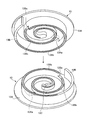
- FIG. 2 is a perspective view of the fixed scroll and the orbiting scroll according to the embodiment of the present invention.
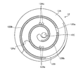
- FIG. 3 is a front view of the fixed scroll according to the embodiment of the present invention.
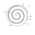
- FIG. 4 is a front view of the orbiting scroll according to the embodiment of the present invention.
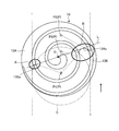
- FIG. 5 is a schematic view showing a method for manufacturing a compressor scroll according to an embodiment of the present invention.
- FIG. 6 is a schematic side view showing the compressor scroll manufacturing apparatus according to the embodiment of the present invention.
- FIG. 1 is a cross-sectional view showing an example of a scroll compressor according to the present embodiment
- FIG. 2 is a perspective view of a fixed scroll and a turning scroll according to the present embodiment
- FIG. 3 is a front view of the fixed scroll according to the present embodiment
- 4 and 4 are front views of the orbiting scroll according to the present embodiment.
- a scroll compressor 10 shown in FIG. 1 is mainly used for compressing a refrigerant of a vehicle air conditioner.
- a scroll compression mechanism including a fixed scroll 12 as a first scroll and a turning scroll 13 as a second scroll is disposed inside a housing 11.
- the housing 11 includes a housing body 11A and a lid body 11B.
- the housing main body 11A has a hollow shape in which a cylindrical large-diameter portion 11Aa and a small-diameter portion 11Ab are integrally formed.
- the large-diameter portion 11Aa side of the housing main body 11A is fixed and closed by a plurality of bolts 20 in a state where the bowl-shaped lid body 11B is fitted to the opening end portion thereof.
- the drive shaft 14 is inserted into the small diameter portion 11Ab side of the housing main body 11A, and the space between the drive shaft 14 and the shaft 11L is sealed. In this way, the housing 11 is configured as a sealed container that wraps the entire scroll compression mechanism.
- the fixed scroll 12 includes an end plate (disk) 12A having a disk shape, and a wall body (lap) 12B formed in a spiral shape standing on one side surface of the end plate 12A, have.
- the fixed scroll 12 is formed on one side of the end plate 12A where the wall body 12B is erected, and is high on the center side along the direction of the vortex of the wall body 12B and low on the outer end side.
- a stepped portion 12Aa is formed so as to be.
- the fixed scroll 12 is formed with a stepped portion 12Ba so as to be lower at the center portion side of the vortex and higher at the outer end side in the wall body 12B.
- the fixed scroll 12 has a groove formed at the edge of the wall body 12B, and a chip seal 12Bb is provided in the groove.
- the fixed scroll 12 is formed with a bypass hole 12Ab in the end plate 12A for preventing over-compression in a compression chamber S1 described later.
- the orbiting scroll 13 has a disk-shaped end plate (disk) 13A and a wall formed in a spiral shape on one side of the end plate 13A, as with the fixed scroll 12. And a body (wrap) 13B.
- the orbiting scroll 13 is provided on one side surface of the end plate 13 ⁇ / b> A where the wall body 13 ⁇ / b> B is erected on the center side along the direction of the vortex of the wall body 13 ⁇ / b> B.
- the step portion 13Aa is formed so as to be higher and lower on the outer terminal side.
- the orbiting scroll 13 is formed with a stepped portion 13Ba so as to be low on the center side of the vortex in the wall body 13B and high on the outer end side.
- the orbiting scroll 13 has a groove formed at the edge of the wall body 13B, and a chip seal 13Bb is provided in the groove.
- the fixed scroll 12 and the orbiting scroll 13 are disposed in the large-diameter portion 11Aa of the housing main body 11A and face one side surfaces of the end plates 12A and 13A so as to face the wall bodies 12B and 13B.
- the compression chamber S1 is formed in a space defined by the end plates 12A, 13A and the wall bodies 12B, 13B in a state where the tip contacts one side surface of the end plates 12A, 13A. Is formed.
- the fixed scroll 12 and the orbiting scroll 13 are engaged with each other with the stepped portions 12Aa and 13Aa and the stepped portions 12Ba and 13Ba in a combined state.
- a suction chamber S3 that communicates with the compression chamber S1 is formed in the outer periphery of the housing main body 11A in which the wall bodies 12B and 13B of the fixed scroll 12 and the orbiting scroll 13 are combined.
- the housing body 11A is formed with a suction port 11Ac for sucking refrigerant gas, and the suction port 11Ac opens into the suction chamber S3.
- the fixed scroll 12 is attached to the lid 11B by a plurality of bolts 21 in a state where the outer peripheral portion of the other side surface of the end plate 12A is in close contact with and fitted to the inner peripheral surface of the lid 11B.
- the discharge chamber S ⁇ b> 2 which is the space between the lid 11 ⁇ / b> B of the housing 11, is defined on the other side of the end plate 12 ⁇ / b> A of the fixed scroll 12.
- the fixed scroll 12 is provided with a discharge port 12 ⁇ / b> C formed so as to penetrate the compression chamber S ⁇ b> 1 and the discharge chamber S ⁇ b> 2 at a position that becomes the spiral center of the wall body 12 ⁇ / b> B in the end plate 12 ⁇ / b> A. Further, the fixed scroll 12 is provided with a discharge valve 12D formed by a leaf spring so that the discharge port 12C is opened only when a pressure of a predetermined magnitude or more is applied to the end plate 12A.
- the orbiting scroll 13 is a shaft which is the extending direction of the drive shaft 14 by the other side surface of the end plate 13A coming into contact with the wall surface 11Ad which is a boundary between the large diameter portion 11Aa and the small diameter portion 11Ab in the housing main body 11A. Movement in the direction is restricted.
- the drive shaft 14 is inserted through the small diameter portion 11Ab of the housing main body 11A.
- the drive shaft 14 has a small diameter portion 11 ⁇ / b> Ab, one end portion 14 ⁇ / b> A is supported by a bearing 22, and a large-diameter disk portion 14 ⁇ / b> B formed at the center portion is supported by a bearing 23, so Is provided.
- an eccentric shaft 14C that is eccentric with respect to the rotation center of the drive shaft 14 is provided integrally with the disk portion 14B.
- the eccentric shaft 14 ⁇ / b> C rotates as the drive shaft 14 rotates.
- the eccentric bush 14C has a balance bush 24 fitted to the outer periphery thereof.
- the balance bush 24 pivots integrally with the eccentric shaft 14C.
- the balance bush 24 is integrally provided with a balance weight 24 ⁇ / b> A for canceling the unbalance amount generated in the orbiting scroll 13.
- a portion of the balance bush 24 fitted to the eccentric shaft 14C is formed in a cylindrical shape, and an annular drive bush 25 is mounted on the outer peripheral portion thereof.
- the orbiting scroll 13 is provided with a boss 13C that protrudes from the central portion on the other side of the end plate 13A.
- the boss 13C is formed with a circular recess 13D having a center at a position that becomes the spiral center of the wall 12B.
- a drive bush 25 is inserted into the recess 13D of the orbiting scroll 13 through a bearing 26 so as to be relatively rotatable.
- the orbiting scroll 13 has a circular rotation restricting recess 13E formed on the outer peripheral portion on the other side of the end plate 13A.
- a plurality of rotation restricting recesses 13E are provided around the recess 13D.
- the rotation restricting recess 13E is inserted with a rotation preventing pin 11Ae fixed to the housing body 11A.
- the rotation preventing pin 11Ae is inserted into the rotation restricting recess 13E, so that the orbiting scroll 13 is prevented from rotating.
- the drive shaft 14 is driven to rotate by the drive unit 15.
- the drive unit 15 includes a pulley 15A that is rotatably supported by a bearing 27 that is mounted on the outer peripheral portion of the small-diameter portion 11Ab of the housing main body 11A.
- the drive unit 15 includes a rotating plate 15 ⁇ / b> B that is fixed to the one end portion 14 ⁇ / b> A of the drive shaft 14 by a nut 28.
- a support ring 15C is connected to the outer peripheral portion of the rotating plate 15B.
- the end face of the pulley 15A is fixed to the support ring 15C.
- the pulley 15A is provided with an electromagnetic clutch 15D therein.
- the pulley 15A receives rotation from a drive source (for example, an engine) via a drive belt (not shown).
- the rotation of the drive source is transmitted to the pulley 15A of the drive unit 15 and the drive shaft 14 rotates while the electromagnetic clutch 15D is released.
- the eccentric shaft 14C is eccentrically rotated.
- the rotational movement of the eccentric shaft 14 ⁇ / b> C is transmitted to the orbiting scroll 13 through the balance bush 24 and the drive bush 25.
- the orbiting scroll 13 revolves while revolving is prevented by the engagement between the rotation restricting recess 13E and the rotation preventing pin 11Ae.
- the refrigerant gas is sucked into the suction chamber S3 in the housing 11 from the suction port 11Ac, and the refrigerant gas in the suction chamber S3 is sucked into the compression chamber S1.
- the compression chamber S1 is gradually narrowed toward the center of the scrolls 12 and 13 and the scroll 12 is compressed while the internal refrigerant gas is compressed by reducing the volume.
- 13 eventually reaches the discharge port 12C, and the discharge valve 12D opens and closes due to the differential pressure between the compression chamber S1 and the discharge chamber S2.
- the refrigerant gas in the compression chamber S1 is compressed and its pressure becomes higher than the pressure in the discharge chamber S2, so that the refrigerant gas pushes the discharge valve 12D open and flows out into the discharge chamber S2. Thereafter, the high-pressure refrigerant gas is discharged from the discharge chamber S2 to the outside of the housing 11 through a discharge port (not shown) formed in the lid 11B, and is introduced into an air conditioner mounted on the vehicle.
- FIG. 5 is a schematic view showing a method for manufacturing a compressor scroll according to the present embodiment.
- FIG. 6 is a schematic side view showing the compressor scroll manufacturing apparatus according to this embodiment.
- the compressor scroll includes the fixed scroll 12 and the orbiting scroll 13 described above, and is hereinafter simply referred to as scroll. Further, in the following description, for the sake of convenience, the orbiting scroll 13 is illustrated and described as a scroll in FIGS. 5 and 6.
- the desired portion where cracks tend to appear remarkably and where compressive residual stress is to be generated is the vicinity of the root of the vortex wall 13 ⁇ / b> B where the stepped portion 13 ⁇ / b> Ba is provided.
- the corners A and B are shaped to easily concentrate stress.
- the corner B is a portion where the corner and the corner meet, and stress is particularly likely to concentrate. Therefore, it is desired that the cavitation bubbles collide with the corners A and B.
- the center P of the cavitation bubble C is located at the corner P1 where the corners A and B are located in a straight line in the spiral passage by the wall body 13B, or at the corner in the spiral passage by the wall body 13B.
- the corners A and B are not positioned on a straight line in the spiral path formed by the wall body 13B. Therefore, the flow of the liquid flow containing the cavitation bubbles C is disturbed by being disturbed by the wall body 13B, so that it is considered that the cavitation bubbles C do not easily collide with the corners A and B.
- the center P of the cavitation bubble C is separated from the spiral center O of the wall 13B in the end plate 13A.
- the stepped portion 13Aa and the stepped portion 13Ba are positioned at the outer peripheral portion of the range of the cavitation bubble C, the position of the center P of the cavitation bubble C is set to the stepped portion 13Aa and the stepped portion 13Ba in the spiral passage formed by the wall body 13B.
- the cavitation bubbles in the corners A and B C can collide. That is, the cavitation bubble C can be appropriately collided with a desired portion of the scroll 13 to generate a compressive residual stress at the desired portion, thereby preventing the occurrence of cracks.
- the water jet peening process includes the positions P1, P2, and P3 of the cavitation bubbles C and the scroll 13, and the step portion 13Aa
- the cavitation bubble C and the scroll 13 are relatively moved so as to intersect a virtual line L connecting the stepped portion 13Ba with a straight line.
- the cavitation bubble C, the scroll 13, the cavitation bubble C and the scroll 13 are moved.
- the cavitation bubble C can be appropriately collided with a desired portion (corners A and B) of the scroll 13 to generate a compressive residual stress at the desired portion and generate a crack. Can be prevented.
- the water jet peening process includes a predetermined relative movement between the cavitation bubble C and the scroll 13 at the positions P1, P2, and P3 between the cavitation bubble C and the scroll 13. Stop for hours.
- the cavitation bubbles C can sufficiently collide with the desired locations (corners A and B) of the scroll 13, generating compressive residual stress at the desired locations, and generating cracks. Occurrence can be prevented.
- the predetermined time is a time required for generating the compressive residual stress at a desired location.
- the water jet peening process is performed before the surface treatment is performed on the scroll 13.
- the surface treatment for example, when the scroll 13 is formed of an aluminum alloy, there is an alumite treatment in which the surface is coated with alumite in order to improve its corrosion resistance and wear resistance.
- this surface treatment is performed, the generation of compressive residual stress due to the collision of the cavitation bubbles C is suppressed, and the effect of preventing the occurrence of cracks may be reduced. Therefore, according to this compressor scroll manufacturing method, the surface of the scroll 13 is subjected to the water jet peening process before the surface treatment is performed, thereby assisting the generation of compressive residual stress due to the collision of the cavitation bubbles C, and cracking.
- production of can be acquired notably.
- the cleaning liquid is mixed in the water that generates the cavitation bubbles C.
- the scroll 13 can be cleaned with the cleaning liquid simultaneously with the water jet peening process.
- the compressor scroll manufacturing apparatus 1 of the present embodiment includes a container 2 filled with water, positioning means 3 for positioning and arranging the scroll 13 in the container 2, Water jet spraying means 4 having a nozzle 4 ⁇ / b> A that is disposed in the water and sprays the water jet J toward the scroll 13.
- the container 2 can obtain a water depth at which the above-described water jet peening process can be performed on the scroll 13 in which the cavitation bubbles C generated by the water jet J ejected from the nozzle 4 ⁇ / b> A are positioned by the positioning means 3. .
- the positioning means 3 positions and arranges the scroll 13 in the container 2 so that the water jet peening process described above can be performed.
- the positioning means 3 includes, for example, an abutting portion 3A that abuts on the other side surface of the end plate 13A in the scroll 13 and a chuck portion 3B that engages at a plurality of locations (for example, three locations) on the periphery of the end plate 13A in the scroll 13. And having.
- the water jet injection unit 4 includes a nozzle 4A, a nozzle support 4B that supports the nozzle 4A, and a high-pressure water pump 4C that supplies high-pressure water to the nozzle 4A.
- the compressor scroll manufacturing apparatus 1 directs the cavitation bubbles C generated in the water in the container 2 by the water jet J of the water jet injection means 4 to one side of the scroll 13 positioned by the positioning means 3.
- the step portion 13Aa and the step portion 13Aa are formed on the outer peripheral portion of the cavitation bubble C.
- the stepped portion 13Ba is positioned.
- the water jet peening process in the above-described compressor scroll manufacturing method can be performed.
- the positioning means 3 is engaged with the end plate 13A of the scroll 13 and a contact portion 3A and a chuck portion 3B which are fixing mechanisms for fixing the scroll 13.
- the scroll 13 is fixed by the fixing mechanism so that the scroll 13 is held when the cavitation bubbles C collide with the scroll 13, and desired portions (corners A and B).
- the cavitation bubbles C can be appropriately collided with each other to generate a compressive residual stress at the desired location, thereby preventing the occurrence of cracks.
- the positioning means 3 includes the positions P1, P2, and P3 of the cavitation bubbles C and the scroll 13, as shown in FIGS. It has a moving mechanism 3C that moves the scroll 13 so as to intersect a virtual line L that connects the step portion 13Aa and the stepped portion 13Ba with a straight line.
- the moving mechanism 3C moves in parallel with the fixing mechanism (the contact part 3A and the chuck part 3B) being supported, and for example, a belt conveyor is preferable.
- the cavitation bubbles C can be appropriately collided with desired portions (corners A and B) of the scroll 13, generating compressive residual stress at the desired portions, Occurrence can be prevented.
- the moving mechanism 3C has a plurality of fixing mechanisms and moves the plurality of scrolls 13.
- the cavitation bubbles C can be made to collide with the desired portions (corners A and B) of the plurality of scrolls 13 in order as appropriate.
- the water jet peening process in the compressor scroll manufacturing method described above can be carried out efficiently.
- the water jet injection means 4 has a turning mechanism 4D for turning the nozzle 4A so that the cavitation bubbles C turn with respect to the scroll 13.
- the turning mechanism 4D is provided in the nozzle support portion 4B, and inclines the injection direction of the water jet J by the nozzle 4A with respect to the vertical line V shown in FIG. 6 and rotates it around a vertical axis.
- the cavitation bubble C directly collides with a desired portion (corner portions A and B) which is an inner corner portion of the end plate 13A and the wall body 13B, the cavitation bubble C is formed at a desired portion of the scroll 13. Can fully collide.
Landscapes
- Engineering & Computer Science (AREA)
- Mechanical Engineering (AREA)
- Chemical & Material Sciences (AREA)
- General Engineering & Computer Science (AREA)
- Crystallography & Structural Chemistry (AREA)
- Materials Engineering (AREA)
- Metallurgy (AREA)
- Organic Chemistry (AREA)
- Rotary Pumps (AREA)
- Applications Or Details Of Rotary Compressors (AREA)
Abstract
A production method for compressor scrolls, whereby cavitation bubbles are caused to appropriately collide at desired locations on a scroll. The production method includes a water jet peening step in which: cavitation bubbles formed by jetting a water jet are jetted on to one side surface of an end plate (13A) of a scroll (13), in water; and a stepped section (13Aa) and a step section (13Ba) are positioned on the outer circumferential section of the cavitation bubbles (C), in a state in which the centers (P1, P2, P3) of the cavitation bubbles are distanced from the helical center (O) of a wall (13B) in the end plate (13A).
Description
本発明は、圧縮機に用いられるスクロールの製造方法、製造装置、圧縮機用スクロールおよびスクロール圧縮機に関するものである。
The present invention relates to a method of manufacturing a scroll used in a compressor, a manufacturing apparatus, a scroll for a compressor, and a scroll compressor.
一般に、スクロール圧縮機は、端板の一側面に渦巻き状の壁体を立設した固定スクロールと、端板の一側面に固定スクロールの壁体と実質的に同一形状の渦巻き状の壁体を立設した旋回スクロールとを有している。そして、固定スクロールと旋回スクロールとの各端板の一側面を向き合わせて互いの壁体を組み合わせて配置する。この状態で固定スクロールに対して旋回スクロールを公転旋回運動させることで各壁体間に形成した圧縮室の容積を漸次減少させて当該圧縮室内の流体を圧縮する。
Generally, a scroll compressor has a fixed scroll in which a spiral wall body is erected on one side surface of an end plate, and a spiral wall body having substantially the same shape as the fixed scroll wall body on one side surface of the end plate. And an upright orbiting scroll. And one side of each end plate of a fixed scroll and a turning scroll is faced, and it arrange | positions combining a mutual wall body. In this state, the orbiting scroll revolves with respect to the fixed scroll, thereby gradually reducing the volume of the compression chamber formed between the walls and compressing the fluid in the compression chamber.
このような圧縮機に用いられるスクロールについて、従来、例えば、特許文献1に記載のスクロール圧縮機の製造方法では、固定または旋回の少なくともいずれかの一方のスクロールの端板(鏡板)の対向側(ラップ側)の面に、硬質微粒子を含んだ液体を噴射することで表面に潤滑油保持のための多数の微小な窪みを設けることが示されている。
With regard to scrolls used in such compressors, conventionally, for example, in the method of manufacturing a scroll compressor described in Patent Document 1, the side opposite to the end plate (end plate) of at least one of fixed and swivel scrolls (end plate) ( It has been shown that a large number of minute depressions for retaining lubricating oil are provided on the surface by injecting a liquid containing hard fine particles on the surface on the lapping side.
一方、従来、例えば、特許文献2に記載の金属材料の残留応力改善方法では、金属材料の溶接部またはその近傍において応力腐食割れが発生することを防止するため、ウォータージェット噴出によりキャビテーション現象によって発生するキャビテーション気泡を含む液体流を金属材料表面に衝突させることで、キャビテーション気泡の崩壊により生じる衝撃力によって金属材料に圧縮残留応力を発生させることが示されている。
On the other hand, conventionally, for example, in the method for improving the residual stress of a metal material described in Patent Document 2, in order to prevent stress corrosion cracks from occurring at or near the welded portion of the metal material, It has been shown that a compressive residual stress is generated in a metal material by an impact force generated by the collapse of the cavitation bubble by causing a liquid flow containing cavitation bubbles to collide with the surface of the metal material.
圧縮機のスクロールは、端板と壁体の繋ぎ部分の隅部に運転時に応力集中が発生して疲労によるクラックが発生しやすい。従って、疲労によるクラックの発生が顕著である上記所望箇所に圧縮側の残留応力を負荷させ、疲労強度の向上を測ることが望ましい。その残留応力の負荷手段としては、ピーニングなどがあるが、通常のショットピーニングなどでは上記所望箇所にはピーニング用の鋼球などがあたらないためスクロールへの適用は適さない。また、ショットピーニングに対してウォータージェットによるキャビテーション気泡は、上記所望箇所のような狭い箇所にも届きやすいのでスクロールへの適用はショットピーニングなどよりも向いている。
Compressor scrolls are prone to fatigue cracks due to stress concentration during operation at the corners of the joint between the end plate and the wall. Therefore, it is desirable to measure the improvement in fatigue strength by applying a compressive residual stress to the desired location where cracks due to fatigue are prominent. As a means for applying the residual stress, there is peening and the like. However, in normal shot peening or the like, since the steel ball for peening does not hit the desired portion, application to a scroll is not suitable. In addition, cavitation bubbles generated by a water jet in a shot peening are likely to reach a narrow part such as the desired part, so that application to scrolling is more suitable than shot peening.
しかし、ウォータージェットによるキャビテーション気泡が向いているとはいっても、スクロールは、端板に壁体が立設された形状であり、特許文献2に示す試験片のような板状ではないため、上記所望箇所にキャビテーション気泡を衝突させ難く、当該所望箇所に圧縮残留応力を発生させることが困難であるという問題があった。
However, even though the cavitation bubbles by the water jet are facing, the scroll has a shape in which a wall body is erected on the end plate, and is not a plate shape like the test piece shown in Patent Document 2, There is a problem that it is difficult to cause cavitation bubbles to collide with a desired location, and it is difficult to generate compressive residual stress at the desired location.
本発明は上述した課題を解決するものであり、スクロールの所望箇所にキャビテーション気泡を適宜衝突させることのできる圧縮機用スクロールの製造方法、製造装置、およびクラックの発生が防止された圧縮機用スクロールおよびスクロール圧縮機を提供することを目的とする。
SUMMARY OF THE INVENTION The present invention solves the above-described problems, and a compressor scroll manufacturing method, a manufacturing apparatus, and a compressor scroll in which cracks are prevented from occurring, which can cause cavitation bubbles to collide with a desired portion of the scroll as appropriate. And to provide a scroll compressor.
上述の目的を達成するために、本発明の圧縮機用スクロールの製造方法は、第一端板の一側面に渦巻き状の第一壁体が設けられた第一スクロールと、第二端板の一側面に渦巻き状の第二壁体が設けられて当該第二壁体を前記第一スクロールの前記第一壁体に対してかみ合わせた状態で自転を阻止されつつ公転旋回可能に支持される第二スクロールと、を有し、各前記端板の各前記一側面の高さを各前記壁体に沿う渦の中心部側で高くし外終端側で低くした段差部、および各前記壁体の高さを渦の中心部側で低くし外終端側で高くして各前記スクロールで相互の前記段差部に係合する段付部が形成された圧縮機用スクロールの製造方法であって、水中にて、ウォータージェットを噴射することで形成されるキャビテーション気泡を前記スクロールにおける前記端板の前記一側面に向けて噴射させ、当該キャビテーション気泡の中心を前記端板における前記壁体の渦巻き状の中心から離隔させた状態で、前記キャビテーション気泡の外周部分に前記段差部および前記段付部を位置させるウォータージェットピーニング工程を含むことを特徴とする。
In order to achieve the above-described object, a compressor scroll manufacturing method according to the present invention includes a first scroll having a spiral first wall provided on one side surface of a first end plate, and a second end plate. A spiral second wall is provided on one side surface, and the second wall is engaged with the first wall of the first scroll and is supported so as to be capable of revolving while being prevented from rotating. A step portion in which the height of the one side surface of each of the end plates is increased on the center side of the vortex along the wall body and is lowered on the outer end side, and each of the wall bodies A method of manufacturing a scroll for a compressor in which a height is lowered at a center portion side of a vortex and is increased at an outer end side to form a stepped portion that engages with the step portion of each scroll. The cavitation bubbles formed by jetting water jets are In the state where the center of the cavitation bubble is separated from the spiral center of the wall body in the end plate, the step portion is formed on the outer peripheral portion of the cavitation bubble. And a water jet peening process for positioning the stepped portion.
この圧縮機用スクロールの製造方法によれば、キャビテーション気泡の中心を端板における壁体の渦巻き状の中心から離隔させた状態で、キャビテーション気泡の範囲の外周部分に段差部および段付部を位置させると、キャビテーション気泡の中心の位置が、壁体による渦巻き状の通路において段差部および段付部近傍の壁体の接合する隅部に至り直線上の位置となり、キャビテーション気泡を含む液体流の流れが壁体により妨害されないため、隅部にキャビテーション気泡を衝突させることができる。つまり、スクロールの所望箇所にキャビテーション気泡を適宜衝突させることができ、当該所望箇所に圧縮残留応力を発生させ、クラックの発生を防止することができる。
According to this compressor scroll manufacturing method, the stepped portion and the stepped portion are positioned on the outer peripheral portion of the range of the cavitation bubble in a state where the center of the cavitation bubble is separated from the spiral center of the wall body in the end plate. Then, the position of the center of the cavitation bubble reaches a corner where the wall body joins the stepped portion and the stepped portion in the spiral passage by the wall body, and becomes a linear position, and the flow of the liquid flow containing the cavitation bubble Since it is not obstructed by the wall, cavitation bubbles can collide with the corners. That is, the cavitation bubbles can be appropriately collided with a desired portion of the scroll, and a compressive residual stress can be generated at the desired portion, thereby preventing the occurrence of cracks.
また、本発明の圧縮機用スクロールの製造方法では、前記ウォータージェットピーニング工程は、前記キャビテーション気泡と前記スクロールとの前記位置を含み、前記段差部と前記段付部とを直線で結ぶ仮想線に交差するように、前記キャビテーション気泡と前記スクロールとを相対移動させることを特徴とする。
Further, in the compressor scroll manufacturing method of the present invention, the water jet peening step includes the position of the cavitation bubble and the scroll, and is a virtual line that connects the stepped portion and the stepped portion with a straight line. The cavitation bubbles and the scroll are relatively moved so as to intersect each other.
この圧縮機用スクロールの製造方法によれば、スクロールの所望箇所(隅部)にキャビテーション気泡を適宜衝突させることができ、当該所望箇所に圧縮残留応力を発生させ、クラックの発生を防止することができる。
According to this method for manufacturing a compressor scroll, cavitation bubbles can be appropriately collided with a desired portion (corner) of the scroll, compressive residual stress can be generated at the desired portion, and cracking can be prevented. it can.
また、本発明の圧縮機用スクロールの製造方法では、前記ウォータージェットピーニング工程は、前記キャビテーション気泡と前記スクロールとの前記位置において、前記キャビテーション気泡と前記スクロールとの相対移動を所定時間停止することを特徴とする。
In the compressor scroll manufacturing method of the present invention, the water jet peening process may stop the relative movement of the cavitation bubble and the scroll for a predetermined time at the position of the cavitation bubble and the scroll. Features.
この圧縮機用スクロールの製造方法によれば、スクロールの所望箇所(隅部)にキャビテーション気泡を十分に衝突させることができ、当該所望箇所に圧縮残留応力を発生させ、クラックの発生を防止することができる。
According to this method for manufacturing a scroll for a compressor, cavitation bubbles can sufficiently collide with a desired portion (corner) of the scroll, and compressive residual stress is generated at the desired portion, thereby preventing the occurrence of cracks. Can do.
また、本発明の圧縮機用スクロールの製造方法では、前記スクロールに表面処理を実施する以前に、前記ウォータージェットピーニング工程を行うことを特徴とする。
Further, in the compressor scroll manufacturing method of the present invention, the water jet peening process is performed before the surface treatment is performed on the scroll.
この圧縮機用スクロールの製造方法によれば、スクロールに表面処理を実施する以前に、ウォータージェットピーニング工程を行うことで、キャビテーション気泡の衝突による圧縮残留応力の発生を助勢し、クラックの発生を防止する効果を顕著に得ることができる。
According to this compressor scroll manufacturing method, the water jet peening process is performed before the surface treatment is applied to the scroll, thereby assisting the generation of compressive residual stress due to the collision of cavitation bubbles and preventing the generation of cracks. The effect to do can be acquired notably.
また、本発明の圧縮機用スクロールの製造方法では、前記キャビテーション気泡を発生させる水中に洗浄液を混入することを特徴とする。
Further, in the method for manufacturing a compressor scroll according to the present invention, a cleaning liquid is mixed in water that generates the cavitation bubbles.
この圧縮機用スクロールの製造方法によれば、ウォータージェットピーニング工程と同時に洗浄液によるスクロールの洗浄を行うことができる。
According to this compressor scroll manufacturing method, the scroll can be cleaned with the cleaning liquid simultaneously with the water jet peening process.
上述の目的を達成するために、本発明の圧縮機用スクロールの製造装置は、第一端板の一側面に渦巻き状の第一壁体が設けられた第一スクロールと、第二端板の一側面に渦巻き状の第二壁体が設けられて当該第二壁体を前記第一スクロールの前記第一壁体に対してかみ合わせた状態で自転を阻止されつつ公転旋回可能に支持される第二スクロールと、を有し、各前記端板の各前記一側面の高さを各前記壁体に沿う渦の中心部側で高くし外終端側で低くした段差部、および各前記壁体の高さを渦の中心部側で低くし外終端側で高くして各前記スクロールで相互の前記段差部に係合する段付部が形成された圧縮機用スクロールの製造装置であって、水が満たされる容器と、前記容器内に前記スクロールを位置決めして配置する位置決手段と、前記容器内の水中に配置されて前記スクロールに向けてウォータージェットを噴射するノズルを有するウォータージェット噴射手段と、を備え、前記ウォータージェット噴射手段のウォータージェットにより前記容器の水中にて生じるキャビテーション気泡を、前記位置決手段により位置決めされた前記スクロールの前記一側面に向けて噴射させ、当該キャビテーション気泡の中心を前記端板における前記壁体の渦巻き状の中心から離隔させた状態で、前記キャビテーション気泡の外周部分に前記段差部および前記段付部を位置させることを特徴とする。
In order to achieve the above-mentioned object, a compressor scroll manufacturing apparatus according to the present invention includes a first scroll having a spiral first wall provided on one side surface of a first end plate, and a second end plate. A spiral second wall is provided on one side surface, and the second wall is engaged with the first wall of the first scroll and is supported so as to be capable of revolving while being prevented from rotating. A step portion in which the height of the one side surface of each of the end plates is increased on the center side of the vortex along the wall body and is lowered on the outer end side, and each of the wall bodies An apparatus for manufacturing a scroll for a compressor, in which a height is lowered at a center portion side of a vortex and is increased at an outer end side to form a stepped portion that engages with each step portion of each scroll, A container that is filled with, a positioning means that positions and arranges the scroll in the container, Water jet spraying means having nozzles that are disposed in the water in the container and spray the water jet toward the scroll, and the cavitation bubbles generated in the water of the container by the water jet of the water jet spraying means, The outer periphery of the cavitation bubble is injected toward the one side surface of the scroll positioned by the positioning means, and the center of the cavitation bubble is separated from the spiral center of the wall body in the end plate. The step portion and the stepped portion are positioned in the portion.
この圧縮機用スクロールの製造装置によれば、上述した圧縮機用スクロールの製造方法におけるウォータージェットピーニング工程を実施できる。
According to the compressor scroll manufacturing apparatus, the water jet peening process in the compressor scroll manufacturing method described above can be performed.
また、本発明の圧縮機用スクロールの製造装置では、前記位置決手段は、前記スクロールにおける前記端板に係合して前記スクロールを固定する固定機構を有することを特徴とする。
In the compressor scroll manufacturing apparatus of the present invention, the positioning means includes a fixing mechanism that engages with the end plate of the scroll to fix the scroll.
この圧縮機用スクロールの製造装置によれば、固定機構によりスクロールを固定することで、キャビテーション気泡がスクロールに衝突する際にスクロールを保持し、所望箇所(隅部)にキャビテーション気泡を適宜衝突させることができ、当該所望箇所に圧縮残留応力を発生させ、クラックの発生を防止することができる。
According to this compressor scroll manufacturing apparatus, the scroll is held by the fixing mechanism, so that the scroll is held when the cavitation bubbles collide with the scroll, and the cavitation bubbles are caused to collide appropriately at a desired location (corner). It is possible to generate a compressive residual stress at the desired location and prevent the occurrence of cracks.
また、本発明の圧縮機用スクロールの製造装置では、前記位置決手段は、前記キャビテーション気泡と前記スクロールとの前記位置を含み、前記段差部と前記段付部とを直線で結ぶ仮想線に交差するように、前記スクロールを移動させる移動機構を有することを特徴とする。
In the compressor scroll manufacturing apparatus of the present invention, the positioning means includes the position of the cavitation bubble and the scroll, and intersects an imaginary line that connects the stepped portion and the stepped portion with a straight line. As described above, it has a moving mechanism for moving the scroll.
この圧縮機用スクロールの製造装置によれば、スクロールの所望箇所(隅部)にキャビテーション気泡を適宜衝突させることができ、当該所望箇所に圧縮残留応力を発生させ、クラックの発生を防止することができる。
According to this compressor scroll manufacturing apparatus, cavitation bubbles can be appropriately collided with a desired portion (corner) of the scroll, and compressive residual stress can be generated at the desired portion, thereby preventing the occurrence of cracks. it can.
また、本発明の圧縮機用スクロールの製造装置では、前記移動機構は、前記固定機構を複数有して複数の前記スクロールを移動させることを特徴とする。
In the compressor scroll manufacturing apparatus of the present invention, the moving mechanism has a plurality of the fixing mechanisms to move the plurality of scrolls.
この圧縮機用スクロールの製造装置によれば、複数のスクロールの所望箇所(隅部)に、順次キャビテーション気泡を適宜衝突させることができる。この結果、上述した圧縮機用スクロールの製造方法におけるウォータージェットピーニング工程を効率的に実施できる。
According to this compressor scroll manufacturing apparatus, cavitation bubbles can be made to collide with a desired portion (corner) of a plurality of scrolls in order. As a result, the water jet peening process in the compressor scroll manufacturing method described above can be carried out efficiently.
また、本発明の圧縮機用スクロールの製造装置では、前記ウォータージェット噴射手段は、前記キャビテーション気泡が前記スクロールに対して旋回するように前記ノズルを旋回移動させる旋回機構を有することを特徴とする。
Further, in the compressor scroll manufacturing apparatus of the present invention, the water jet injection means has a turning mechanism for turning the nozzle so that the cavitation bubbles turn with respect to the scroll.
この圧縮機用スクロールの製造装置によれば、端板と壁体との内角部である所望箇所(隅部)に対してキャビテーション気泡が直接衝突するため、スクロールの所望箇所にキャビテーション気泡を十分に衝突させることができる。
According to this compressor scroll manufacturing apparatus, since the cavitation bubbles directly collide with a desired portion (corner portion) which is an inner corner portion between the end plate and the wall body, the cavitation bubbles are sufficiently applied to the desired portion of the scroll. It can be made to collide.
上述の目的を達成するために、本発明の圧縮機用スクロールは、上述した圧縮機用スクロールの製造装置を用いて作成されたことを特徴とする。
In order to achieve the above-described object, the compressor scroll according to the present invention is produced using the above-described compressor scroll manufacturing apparatus.
この圧縮機用スクロールによれば、クラックの発生が防止され、当該クラックに基づく故障の発生を低減することができる。
According to this compressor scroll, the occurrence of cracks can be prevented and the occurrence of failures based on the cracks can be reduced.
上述の目的を達成するために、本発明のスクロール圧縮機は、上述した圧縮機用スクロールが適用されたことを特徴とする。
In order to achieve the above object, the scroll compressor according to the present invention is characterized in that the above-described compressor scroll is applied.
このスクロール圧縮機によれば、スクロールにおけるクラックの発生が防止され、当該クラックに基づく故障の発生を低減することができる。
According to this scroll compressor, the occurrence of cracks in the scroll can be prevented, and the occurrence of failures based on the cracks can be reduced.
本発明によれば、スクロールの所望箇所にキャビテーション気泡を適宜衝突させることができる。
According to the present invention, cavitation bubbles can be collided with a desired portion of the scroll as appropriate.
以下に、本発明に係る実施形態を図面に基づいて詳細に説明する。なお、この実施形態によりこの発明が限定されるものではない。また、下記実施形態における構成要素には、当業者が置換可能かつ容易なもの、あるいは実質的に同一のものが含まれる。
Hereinafter, embodiments of the present invention will be described in detail with reference to the drawings. In addition, this invention is not limited by this embodiment. In addition, constituent elements in the following embodiments include those that can be easily replaced by those skilled in the art or those that are substantially the same.
図1は、本実施形態に係るスクロール圧縮機の一例をあらわす断面図、図2は、本実施形態に係る固定スクロールおよび旋回スクロールの斜視図、図3は、本実施形態に係る固定スクロールの正面図、図4は、本実施形態に係る旋回スクロールの正面図である。
1 is a cross-sectional view showing an example of a scroll compressor according to the present embodiment, FIG. 2 is a perspective view of a fixed scroll and a turning scroll according to the present embodiment, and FIG. 3 is a front view of the fixed scroll according to the present embodiment. 4 and 4 are front views of the orbiting scroll according to the present embodiment.
図1に示すスクロール圧縮機10は、主として車両用空調装置の冷媒を圧縮するために用いられる。このスクロール圧縮機10は、ハウジング11の内部に、第一スクロールとしての固定スクロール12および第二スクロールとしての旋回スクロール13からなるスクロール圧縮機構が配設される。
A scroll compressor 10 shown in FIG. 1 is mainly used for compressing a refrigerant of a vehicle air conditioner. In the scroll compressor 10, a scroll compression mechanism including a fixed scroll 12 as a first scroll and a turning scroll 13 as a second scroll is disposed inside a housing 11.
ハウジング11は、ハウジング本体11Aと蓋体11Bとで構成されている。ハウジング本体11Aは、筒状の大径部11Aaと小径部11Abとが一体に形成された中空形状である。ハウジング本体11Aの大径部11Aa側は、その開口端部にお椀型の蓋体11Bが嵌合した状態で、複数のボルト20により固定されて閉塞される。ハウジング本体11Aの小径部11Ab側は、駆動軸14が挿通され、軸シール11Dにより駆動軸14との間が封止される。このようにして、ハウジング11は、スクロール圧縮機構全体を包む密閉容器として構成される。
The housing 11 includes a housing body 11A and a lid body 11B. The housing main body 11A has a hollow shape in which a cylindrical large-diameter portion 11Aa and a small-diameter portion 11Ab are integrally formed. The large-diameter portion 11Aa side of the housing main body 11A is fixed and closed by a plurality of bolts 20 in a state where the bowl-shaped lid body 11B is fitted to the opening end portion thereof. The drive shaft 14 is inserted into the small diameter portion 11Ab side of the housing main body 11A, and the space between the drive shaft 14 and the shaft 11L is sealed. In this way, the housing 11 is configured as a sealed container that wraps the entire scroll compression mechanism.
固定スクロール12は、図2に示すように、円盤形状をなす端板(ディスク)12Aと、この端板12Aの一側面に立設して渦巻き状に形成された壁体(ラップ)12Bと、を有している。
As shown in FIG. 2, the fixed scroll 12 includes an end plate (disk) 12A having a disk shape, and a wall body (lap) 12B formed in a spiral shape standing on one side surface of the end plate 12A, have.
固定スクロール12は、図2および図3に示すように、端板12Aにおいて壁体12Bを立設した一側面に、壁体12Bの渦の方向に沿って中心部側で高く外終端側で低くなるように段差部12Aaが形成されている。また、固定スクロール12は、壁体12Bにおいて渦の中心部側で低く外終端側で高くなるように段付部12Baが形成されている。さらに、固定スクロール12は、壁体12Bの端縁に溝が形成され、当該溝にチップシール12Bbが設けられる。なお、本実施形態において、固定スクロール12は、図3に示すように、端板12Aにおいて後述する圧縮室S1における過大圧縮を防止するためのバイパス孔12Abが形成されている。
As shown in FIGS. 2 and 3, the fixed scroll 12 is formed on one side of the end plate 12A where the wall body 12B is erected, and is high on the center side along the direction of the vortex of the wall body 12B and low on the outer end side. A stepped portion 12Aa is formed so as to be. Further, the fixed scroll 12 is formed with a stepped portion 12Ba so as to be lower at the center portion side of the vortex and higher at the outer end side in the wall body 12B. Further, the fixed scroll 12 has a groove formed at the edge of the wall body 12B, and a chip seal 12Bb is provided in the groove. In the present embodiment, as shown in FIG. 3, the fixed scroll 12 is formed with a bypass hole 12Ab in the end plate 12A for preventing over-compression in a compression chamber S1 described later.
旋回スクロール13は、図2に示すように、固定スクロール12と同様に、円盤形状をなす端板(ディスク)13Aと、この端板13Aの一側面に立設して渦巻き状に形成された壁体(ラップ)13Bと、を有している。
As shown in FIG. 2, the orbiting scroll 13 has a disk-shaped end plate (disk) 13A and a wall formed in a spiral shape on one side of the end plate 13A, as with the fixed scroll 12. And a body (wrap) 13B.
旋回スクロール13は、図2および図4に示すように、固定スクロール12と同様に、端板13Aにおいて壁体13Bを立設した一側面に、壁体13Bの渦の方向に沿って中心部側で高く外終端側で低くなるように段差部13Aaが形成されている。また、旋回スクロール13は、壁体13Bにおいて渦の中心部側で低く外終端側で高くなるように段付部13Baが形成されている。さらに、旋回スクロール13は、壁体13Bの端縁に溝が形成され、当該溝にチップシール13Bbが設けられる。
As shown in FIGS. 2 and 4, the orbiting scroll 13 is provided on one side surface of the end plate 13 </ b> A where the wall body 13 </ b> B is erected on the center side along the direction of the vortex of the wall body 13 </ b> B. The step portion 13Aa is formed so as to be higher and lower on the outer terminal side. Further, the orbiting scroll 13 is formed with a stepped portion 13Ba so as to be low on the center side of the vortex in the wall body 13B and high on the outer end side. Further, the orbiting scroll 13 has a groove formed at the edge of the wall body 13B, and a chip seal 13Bb is provided in the groove.
これら、固定スクロール12および旋回スクロール13は、図1に示すように、ハウジング本体11Aの大径部11Aa内に配設され、相互の端板12A,13Aの一側面を対向し壁体12B,13Bが180°だけ位相をずらして噛み合うように組み合わされて先端が端板12A,13Aの一側面に接触した状態で、端板12A,13Aおよび壁体12B,13Bで区画された空間に圧縮室S1が形成される。この際、固定スクロール12および旋回スクロール13は、相互に組み合わされた状態で、相互の段差部12Aa,13Aaと段付部12Ba,13Baとが係合することになる。また、図1に示すように、ハウジング本体11A内において、固定スクロール12および旋回スクロール13の各壁体12B,13Bが組み合わされた外周に、圧縮室S1に通じる吸入室S3が形成される。そして、ハウジング本体11Aは、冷媒ガスを吸入する吸入口11Acが形成され、この吸入口11Acが吸入室S3に開口している。
As shown in FIG. 1, the fixed scroll 12 and the orbiting scroll 13 are disposed in the large-diameter portion 11Aa of the housing main body 11A and face one side surfaces of the end plates 12A and 13A so as to face the wall bodies 12B and 13B. Are combined so as to engage with each other with a phase shift of 180 °, and the compression chamber S1 is formed in a space defined by the end plates 12A, 13A and the wall bodies 12B, 13B in a state where the tip contacts one side surface of the end plates 12A, 13A. Is formed. At this time, the fixed scroll 12 and the orbiting scroll 13 are engaged with each other with the stepped portions 12Aa and 13Aa and the stepped portions 12Ba and 13Ba in a combined state. Further, as shown in FIG. 1, a suction chamber S3 that communicates with the compression chamber S1 is formed in the outer periphery of the housing main body 11A in which the wall bodies 12B and 13B of the fixed scroll 12 and the orbiting scroll 13 are combined. The housing body 11A is formed with a suction port 11Ac for sucking refrigerant gas, and the suction port 11Ac opens into the suction chamber S3.
また、固定スクロール12は、図1に示すように、端板12Aの他側面の外周部が蓋体11Bの内周面に密着、かつ嵌合した状態で、複数のボルト21により蓋体11Bに対して複数箇所で固定される。このようにして、固定スクロール12の端板12Aの他側に、ハウジング11の蓋体11Bとの間の空間である吐出室S2が区画される。固定スクロール12は、端板12Aにおいて壁体12Bの渦巻き状の中央となる位置に、圧縮室S1および吐出室S2に通じるように貫通して形成された吐出ポート12Cが設けられている。また、固定スクロール12は、端板12Aに、所定の大きさ以上の圧力が作用した場合にのみ吐出ポート12Cを開くように板バネにより形成された吐出弁12Dが設けられている。
Further, as shown in FIG. 1, the fixed scroll 12 is attached to the lid 11B by a plurality of bolts 21 in a state where the outer peripheral portion of the other side surface of the end plate 12A is in close contact with and fitted to the inner peripheral surface of the lid 11B. On the other hand, it is fixed at multiple locations. In this way, the discharge chamber S <b> 2, which is the space between the lid 11 </ b> B of the housing 11, is defined on the other side of the end plate 12 </ b> A of the fixed scroll 12. The fixed scroll 12 is provided with a discharge port 12 </ b> C formed so as to penetrate the compression chamber S <b> 1 and the discharge chamber S <b> 2 at a position that becomes the spiral center of the wall body 12 </ b> B in the end plate 12 </ b> A. Further, the fixed scroll 12 is provided with a discharge valve 12D formed by a leaf spring so that the discharge port 12C is opened only when a pressure of a predetermined magnitude or more is applied to the end plate 12A.
また、旋回スクロール13は、端板13Aの他側面がハウジング本体11A内における大径部11Aaと小径部11Abとの境となる壁面11Adに当接することで、駆動軸14の延在方向である軸方向への移動が規制される。
Further, the orbiting scroll 13 is a shaft which is the extending direction of the drive shaft 14 by the other side surface of the end plate 13A coming into contact with the wall surface 11Ad which is a boundary between the large diameter portion 11Aa and the small diameter portion 11Ab in the housing main body 11A. Movement in the direction is restricted.
駆動軸14は、上述したように、ハウジング本体11Aの小径部11Abに挿通されている。駆動軸14は、図1に示すように、小径部11Ab内において、一端部14Aが軸受22により支持され、中央部に形成された大径の円盤部14Bが軸受23により支持されて、回転自在に設けられている。また、駆動軸14は、その他端部において、駆動軸14の回転中心に対して偏心した偏心軸14Cが円盤部14Bに一体に設けられている。この偏心軸14Cは、駆動軸14の回転に伴って旋回移動する。
As described above, the drive shaft 14 is inserted through the small diameter portion 11Ab of the housing main body 11A. As shown in FIG. 1, the drive shaft 14 has a small diameter portion 11 </ b> Ab, one end portion 14 </ b> A is supported by a bearing 22, and a large-diameter disk portion 14 </ b> B formed at the center portion is supported by a bearing 23, so Is provided. Further, at the other end of the drive shaft 14, an eccentric shaft 14C that is eccentric with respect to the rotation center of the drive shaft 14 is provided integrally with the disk portion 14B. The eccentric shaft 14 </ b> C rotates as the drive shaft 14 rotates.
偏心軸14Cは、その外周部にバランスブッシュ24が嵌合されている。バランスブッシュ24は、偏心軸14Cと一体に旋回移動する。また、バランスブッシュ24は、旋回スクロール13に生じるアンバランス量を打ち消すためのバランスウェイト24Aが一体に設けられている。バランスブッシュ24の偏心軸14Cに嵌合された部分は、円柱形状に形成され、その外周部に円環状のドライブブッシュ25が装着されている。
The eccentric bush 14C has a balance bush 24 fitted to the outer periphery thereof. The balance bush 24 pivots integrally with the eccentric shaft 14C. The balance bush 24 is integrally provided with a balance weight 24 </ b> A for canceling the unbalance amount generated in the orbiting scroll 13. A portion of the balance bush 24 fitted to the eccentric shaft 14C is formed in a cylindrical shape, and an annular drive bush 25 is mounted on the outer peripheral portion thereof.
その一方で、旋回スクロール13は、端板13Aの他側の中央部に突出するボス13Cが設けられている。ボス13Cには、壁体12Bの渦巻き状の中央となる位置に中心を有する円形状の凹部13Dが形成されている。そして、この旋回スクロール13の凹部13Dに、軸受26を介して相対回転可能にドライブブッシュ25が挿入されている。また、旋回スクロール13は、端板13Aの他側の外周部に円形状の自転規制凹部13Eが形成されている。自転規制凹部13Eは、凹部13Dを中心として複数設けられている。この自転規制凹部13Eは、ハウジング本体11Aに固定された自転防止ピン11Aeが挿入されている。自転防止ピン11Aeが自転規制凹部13Eに挿入することで、旋回スクロール13の自転が阻止される。
On the other hand, the orbiting scroll 13 is provided with a boss 13C that protrudes from the central portion on the other side of the end plate 13A. The boss 13C is formed with a circular recess 13D having a center at a position that becomes the spiral center of the wall 12B. A drive bush 25 is inserted into the recess 13D of the orbiting scroll 13 through a bearing 26 so as to be relatively rotatable. The orbiting scroll 13 has a circular rotation restricting recess 13E formed on the outer peripheral portion on the other side of the end plate 13A. A plurality of rotation restricting recesses 13E are provided around the recess 13D. The rotation restricting recess 13E is inserted with a rotation preventing pin 11Ae fixed to the housing body 11A. The rotation preventing pin 11Ae is inserted into the rotation restricting recess 13E, so that the orbiting scroll 13 is prevented from rotating.
また、駆動軸14は、駆動部15により回転を駆動される。駆動部15は、ハウジング本体11Aの小径部11Abの外周部に装着された軸受27により回転自在に支持されたプーリ15Aを有する。また、駆動部15は、駆動軸14の一端部14Aに対してナット28により固定された回転板15Bを有する。回転板15Bは、その外周部に支持リング15Cが連結されている。そして、この支持リング15Cにプーリ15Aの端面が固定されている。また、プーリ15Aは、その内部に電磁クラッチ15Dが設けられている。このプーリ15Aは、図示しない駆動ベルトを介して駆動源(例えば、エンジン)からの回転が伝達される。
Further, the drive shaft 14 is driven to rotate by the drive unit 15. The drive unit 15 includes a pulley 15A that is rotatably supported by a bearing 27 that is mounted on the outer peripheral portion of the small-diameter portion 11Ab of the housing main body 11A. In addition, the drive unit 15 includes a rotating plate 15 </ b> B that is fixed to the one end portion 14 </ b> A of the drive shaft 14 by a nut 28. A support ring 15C is connected to the outer peripheral portion of the rotating plate 15B. The end face of the pulley 15A is fixed to the support ring 15C. Further, the pulley 15A is provided with an electromagnetic clutch 15D therein. The pulley 15A receives rotation from a drive source (for example, an engine) via a drive belt (not shown).
このように構成されたスクロール圧縮機10は、電磁クラッチ15Dが解除されている状態で、駆動源の回転が駆動部15のプーリ15Aに伝達され駆動軸14が回転する。この駆動軸14の回転により、偏心軸14Cが偏心して回転移動する。そして、偏心軸14Cの回転移動が、バランスブッシュ24およびドライブブッシュ25を介して旋回スクロール13に伝達される。旋回スクロール13は、自転規制凹部13Eと自転防止ピン11Aeとの係合により自転が阻止されながら公転旋回する。これにより、冷媒ガスが吸入口11Acからハウジング11内の吸入室S3に吸い込まれ、この吸入室S3の冷媒ガスが圧縮室S1に吸い込まれる。そして、旋回スクロール13が旋回を続けると、これに伴って圧縮室S1が各スクロール12,13の中央に向かって次第に狭められ、容積が減少することで内部の冷媒ガスが圧縮されながら各スクロール12,13の中央部に流動し、やがて吐出ポート12Cに至り、吐出弁12Dが圧縮室S1と吐出室S2との差圧により開閉する。即ち、圧縮室S1の冷媒ガスが圧縮されてその圧力が吐出室S2の圧力よりも高くなることで、この冷媒ガスが吐出弁12Dを押し開いて吐出室S2に流出する。その後、高圧の冷媒ガスは、吐出室S2から蓋体11Bに形成された吐出口(図示せず)を経てハウジング11の外部に吐き出され、車両に搭載された空調機に導入される。
In the scroll compressor 10 configured as described above, the rotation of the drive source is transmitted to the pulley 15A of the drive unit 15 and the drive shaft 14 rotates while the electromagnetic clutch 15D is released. By the rotation of the drive shaft 14, the eccentric shaft 14C is eccentrically rotated. Then, the rotational movement of the eccentric shaft 14 </ b> C is transmitted to the orbiting scroll 13 through the balance bush 24 and the drive bush 25. The orbiting scroll 13 revolves while revolving is prevented by the engagement between the rotation restricting recess 13E and the rotation preventing pin 11Ae. Thus, the refrigerant gas is sucked into the suction chamber S3 in the housing 11 from the suction port 11Ac, and the refrigerant gas in the suction chamber S3 is sucked into the compression chamber S1. When the orbiting scroll 13 continues to orbit, the compression chamber S1 is gradually narrowed toward the center of the scrolls 12 and 13 and the scroll 12 is compressed while the internal refrigerant gas is compressed by reducing the volume. , 13 eventually reaches the discharge port 12C, and the discharge valve 12D opens and closes due to the differential pressure between the compression chamber S1 and the discharge chamber S2. That is, the refrigerant gas in the compression chamber S1 is compressed and its pressure becomes higher than the pressure in the discharge chamber S2, so that the refrigerant gas pushes the discharge valve 12D open and flows out into the discharge chamber S2. Thereafter, the high-pressure refrigerant gas is discharged from the discharge chamber S2 to the outside of the housing 11 through a discharge port (not shown) formed in the lid 11B, and is introduced into an air conditioner mounted on the vehicle.
以下、本実施形態の圧縮機用スクロールの製造方法および製造装置について説明する。図5は、本実施形態に係る圧縮機用スクロールの製造方法をあらわす概略図である。図6は、本実施形態に係る圧縮機用スクロールの製造装置をあらわす概略側面図である。なお、以下の説明において、圧縮機用スクロールとは、上述した固定スクロール12および旋回スクロール13を含んでおり、以下では、単にスクロールという。また、以下の説明では、便宜上、スクロールとして図5および図6に旋回スクロール13を図示して説明する。
Hereinafter, the manufacturing method and manufacturing apparatus of the scroll for compressors of this embodiment are demonstrated. FIG. 5 is a schematic view showing a method for manufacturing a compressor scroll according to the present embodiment. FIG. 6 is a schematic side view showing the compressor scroll manufacturing apparatus according to this embodiment. In the following description, the compressor scroll includes the fixed scroll 12 and the orbiting scroll 13 described above, and is hereinafter simply referred to as scroll. Further, in the following description, for the sake of convenience, the orbiting scroll 13 is illustrated and described as a scroll in FIGS. 5 and 6.
本実施形態の圧縮機用スクロールの製造方法および製造装置は、スクロール13の端板13Aと壁体13Bとの隅部におけるクラック発生を改善するため、当該隅部に対し、水中にてウォータージェットの噴出によりキャビテーション現象によって発生するキャビテーション気泡を含む液体流を衝突させることで、キャビテーション気泡の崩壊により生じる衝撃力によって金属材料に圧縮残留応力を発生させる。
In the compressor scroll manufacturing method and manufacturing apparatus according to the present embodiment, in order to improve the generation of cracks at the corners of the end plate 13A and the wall body 13B of the scroll 13, By colliding a liquid flow containing cavitation bubbles generated by the cavitation phenomenon by jetting, a compressive residual stress is generated in the metal material by an impact force generated by the collapse of the cavitation bubbles.
ここで、クラックが顕著に表れやすい部分であって、圧縮残留応力を発生させたい所望箇所は、図5に示すように、段付部13Baが設けられている付近の渦の壁体13B付け根の隅部A、および段差部13Aaが設けられている付近の渦の壁体13B付け根の各隅部Bがある。この隅部A,Bは応力集中をしやすい形状となっている。また、特にこの隅部Bは隅部と隅部が合流する部分になり特に応力集中しやすい。そのため隅部A,Bにキャビテーション気泡を衝突させることが望まれる。
Here, as shown in FIG. 5, the desired portion where cracks tend to appear remarkably and where compressive residual stress is to be generated is the vicinity of the root of the vortex wall 13 </ b> B where the stepped portion 13 </ b> Ba is provided. There are corners A and corners B of the vortex wall body 13B root in the vicinity where the stepped portion 13Aa is provided. The corners A and B are shaped to easily concentrate stress. In particular, the corner B is a portion where the corner and the corner meet, and stress is particularly likely to concentrate. Therefore, it is desired that the cavitation bubbles collide with the corners A and B.
そこで、本実施形態の圧縮機用スクロールの製造方法では、図5に示すように、ウォータージェットピーニング工程として、スクロール13における端板13Aの一側面に向けてキャビテーション気泡Cを噴射させ、当該キャビテーション気泡Cの中心Pを端板13Aにおける壁体13Bの渦巻き状の中心Oから離隔させた状態で、キャビテーション気泡Cの範囲(図5中二点鎖線で示す円の範囲)の外周部分に段差部13Aaおよび段付部13Baを位置させる。キャビテーション気泡Cの中心Pの位置は、図5に示すように、壁体13Bによる渦巻き状の通路において隅部A,Bが直線上に位置するP1や、壁体13Bによる渦巻き状の通路において隅部Bが直線上に位置するP2や、壁体13Bによる渦巻き状の通路において隅部Bが直線上に位置するP3がある。
Therefore, in the compressor scroll manufacturing method of the present embodiment, as shown in FIG. 5, as a water jet peening process, cavitation bubbles C are jetted toward one side surface of the end plate 13A of the scroll 13, and the cavitation bubbles are generated. In a state where the center P of C is separated from the spiral center O of the wall 13B in the end plate 13A, a stepped portion 13Aa is formed at the outer peripheral portion of the range of the cavitation bubble C (the range indicated by the two-dot chain line in FIG. 5). And the stepped portion 13Ba is positioned. As shown in FIG. 5, the center P of the cavitation bubble C is located at the corner P1 where the corners A and B are located in a straight line in the spiral passage by the wall body 13B, or at the corner in the spiral passage by the wall body 13B. There are P2 where the part B is located on a straight line and P3 where the corner B is located on a straight line in the spiral passage formed by the wall body 13B.
例えば、キャビテーション気泡Cの中心Pを端板13Aにおける壁体13Bの渦巻き状の中心O上に位置させた場合、壁体13Bによる渦巻き状の通路において隅部A,Bが直線上に位置しないことから、キャビテーション気泡Cを含む液体流の流れが壁体13Bにより妨害されて乱れるため、隅部A,Bにキャビテーション気泡Cが衝突し難くなっているものと考えられる。
For example, when the center P of the cavitation bubble C is positioned on the spiral center O of the wall body 13B in the end plate 13A, the corners A and B are not positioned on a straight line in the spiral path formed by the wall body 13B. Therefore, the flow of the liquid flow containing the cavitation bubbles C is disturbed by being disturbed by the wall body 13B, so that it is considered that the cavitation bubbles C do not easily collide with the corners A and B.
これに対し、本実施形態の圧縮機用スクロールの製造方法によれば、上述したように、キャビテーション気泡Cの中心Pを端板13Aにおける壁体13Bの渦巻き状の中心Oから離隔させた状態で、キャビテーション気泡Cの範囲の外周部分に段差部13Aaおよび段付部13Baを位置させると、キャビテーション気泡Cの中心Pの位置が、壁体13Bによる渦巻き状の通路において段差部13Aaおよび段付部13Ba近傍の壁体13Bの隅部A,Bに至り直線上の位置P1,P2,P3となり、キャビテーション気泡Cを含む液体流の流れが壁体13Bにより妨害されないため、隅部A,Bにキャビテーション気泡Cを衝突させることができる。つまり、スクロール13の所望箇所にキャビテーション気泡Cを適宜衝突させることができ、当該所望箇所に圧縮残留応力を発生させ、クラックの発生を防止することができる。
On the other hand, according to the compressor scroll manufacturing method of the present embodiment, as described above, the center P of the cavitation bubble C is separated from the spiral center O of the wall 13B in the end plate 13A. When the stepped portion 13Aa and the stepped portion 13Ba are positioned at the outer peripheral portion of the range of the cavitation bubble C, the position of the center P of the cavitation bubble C is set to the stepped portion 13Aa and the stepped portion 13Ba in the spiral passage formed by the wall body 13B. Since it reaches the corners A and B of the nearby wall body 13B and becomes positions P1, P2 and P3 on a straight line and the flow of the liquid flow containing the cavitation bubbles C is not obstructed by the wall body 13B, the cavitation bubbles in the corners A and B C can collide. That is, the cavitation bubble C can be appropriately collided with a desired portion of the scroll 13 to generate a compressive residual stress at the desired portion, thereby preventing the occurrence of cracks.
また、本実施形態の圧縮機用スクロールの製造方法では、図5に示すように、ウォータージェットピーニング工程は、キャビテーション気泡Cとスクロール13との前記位置P1,P2,P3を含み、段差部13Aaと段付部13Baとを直線で結ぶ仮想線Lに交差するように、キャビテーション気泡Cとスクロール13とを相対移動させる。移動に関しては、キャビテーション気泡Cや、スクロール13や、キャビテーション気泡Cおよびスクロール13を移動させる。
Further, in the compressor scroll manufacturing method of the present embodiment, as shown in FIG. 5, the water jet peening process includes the positions P1, P2, and P3 of the cavitation bubbles C and the scroll 13, and the step portion 13Aa The cavitation bubble C and the scroll 13 are relatively moved so as to intersect a virtual line L connecting the stepped portion 13Ba with a straight line. Regarding the movement, the cavitation bubble C, the scroll 13, the cavitation bubble C and the scroll 13 are moved.
この圧縮機用スクロールの製造方法によれば、スクロール13の所望箇所(隅部A,B)にキャビテーション気泡Cを適宜衝突させることができ、当該所望箇所に圧縮残留応力を発生させ、クラックの発生を防止することができる。
According to this compressor scroll manufacturing method, the cavitation bubble C can be appropriately collided with a desired portion (corners A and B) of the scroll 13 to generate a compressive residual stress at the desired portion and generate a crack. Can be prevented.
また、本実施形態の圧縮機用スクロールの製造方法では、ウォータージェットピーニング工程は、キャビテーション気泡Cとスクロール13との前記位置P1,P2,P3において、キャビテーション気泡Cとスクロール13との相対移動を所定時間停止する。
In the compressor scroll manufacturing method according to the present embodiment, the water jet peening process includes a predetermined relative movement between the cavitation bubble C and the scroll 13 at the positions P1, P2, and P3 between the cavitation bubble C and the scroll 13. Stop for hours.
この圧縮機用スクロールの製造方法によれば、スクロール13の所望箇所(隅部A,B)にキャビテーション気泡Cを十分に衝突させることができ、当該所望箇所に圧縮残留応力を発生させ、クラックの発生を防止することができる。なお、所定時間とは、所望箇所に圧縮残留応力を発生させる所要時間である。
According to this compressor scroll manufacturing method, the cavitation bubbles C can sufficiently collide with the desired locations (corners A and B) of the scroll 13, generating compressive residual stress at the desired locations, and generating cracks. Occurrence can be prevented. The predetermined time is a time required for generating the compressive residual stress at a desired location.
また、本実施形態の圧縮機用スクロールの製造方法では、スクロール13に表面処理を実施する以前に、ウォータージェットピーニング工程を行う。
In the compressor scroll manufacturing method of the present embodiment, the water jet peening process is performed before the surface treatment is performed on the scroll 13.
表面処理は、例えば、スクロール13がアルミニウム合金で形成される場合に、その耐食性および耐摩耗性の向上を図るために表面をアルマイトでコーティングするアルマイト処理がある。この表面処理を実施すると、キャビテーション気泡Cの衝突による圧縮残留応力の発生が抑えられ、クラックの発生を防止する効果が低下するおそれがある。従って、この圧縮機用スクロールの製造方法によれば、スクロール13に表面処理を実施する以前に、ウォータージェットピーニング工程を行うことで、キャビテーション気泡Cの衝突による圧縮残留応力の発生を助勢し、クラックの発生を防止する効果を顕著に得ることができる。
As the surface treatment, for example, when the scroll 13 is formed of an aluminum alloy, there is an alumite treatment in which the surface is coated with alumite in order to improve its corrosion resistance and wear resistance. When this surface treatment is performed, the generation of compressive residual stress due to the collision of the cavitation bubbles C is suppressed, and the effect of preventing the occurrence of cracks may be reduced. Therefore, according to this compressor scroll manufacturing method, the surface of the scroll 13 is subjected to the water jet peening process before the surface treatment is performed, thereby assisting the generation of compressive residual stress due to the collision of the cavitation bubbles C, and cracking. The effect which prevents generation | occurrence | production of can be acquired notably.
また、本実施形態の圧縮機用スクロールの製造方法では、キャビテーション気泡Cを発生させる水中に洗浄液を混入する。
In the compressor scroll manufacturing method of the present embodiment, the cleaning liquid is mixed in the water that generates the cavitation bubbles C.
この圧縮機用スクロールの製造方法によれば、ウォータージェットピーニング工程と同時に洗浄液によるスクロール13の洗浄を行うことができる。
According to the compressor scroll manufacturing method, the scroll 13 can be cleaned with the cleaning liquid simultaneously with the water jet peening process.
ここで、上述した圧縮機用スクロールの製造方法を実施するための圧縮機用スクロールの製造装置について説明する。
Here, a compressor scroll manufacturing apparatus for carrying out the above-described compressor scroll manufacturing method will be described.
本実施形態の圧縮機用スクロールの製造装置1は、図6に示すように、水が満たされる容器2と、容器2内にスクロール13を位置決めして配置する位置決手段3と、容器2内の水中に配置されてスクロール13に向けてウォータージェットJを噴射するノズル4Aを有するウォータージェット噴射手段4と、を備える。
As shown in FIG. 6, the compressor scroll manufacturing apparatus 1 of the present embodiment includes a container 2 filled with water, positioning means 3 for positioning and arranging the scroll 13 in the container 2, Water jet spraying means 4 having a nozzle 4 </ b> A that is disposed in the water and sprays the water jet J toward the scroll 13.
容器2は、ノズル4Aから噴射されたウォータージェットJにより生じるキャビテーション気泡Cが、位置決手段3により位置決めされたスクロール13に対して、上述したウォータージェットピーニング工程を実施できる水深が得られるものである。
The container 2 can obtain a water depth at which the above-described water jet peening process can be performed on the scroll 13 in which the cavitation bubbles C generated by the water jet J ejected from the nozzle 4 </ b> A are positioned by the positioning means 3. .
位置決手段3は、上述したウォータージェットピーニング工程を実施できるように、容器2内でスクロール13を位置決めして配置するものである。位置決手段3は、例えば、スクロール13における端板13Aの他側面に当接する当接部3Aと、スクロール13における端板13Aの周縁の複数箇所(例えば、3箇所)に係合するチャック部3Bと、を有する。
The positioning means 3 positions and arranges the scroll 13 in the container 2 so that the water jet peening process described above can be performed. The positioning means 3 includes, for example, an abutting portion 3A that abuts on the other side surface of the end plate 13A in the scroll 13 and a chuck portion 3B that engages at a plurality of locations (for example, three locations) on the periphery of the end plate 13A in the scroll 13. And having.
ウォータージェット噴射手段4は、ノズル4Aと、ノズル4Aを支持するノズル支持部4Bと、ノズル4Aに高圧水を供給する高圧水ポンプ4Cと、を有する。
The water jet injection unit 4 includes a nozzle 4A, a nozzle support 4B that supports the nozzle 4A, and a high-pressure water pump 4C that supplies high-pressure water to the nozzle 4A.
そして、この圧縮機用スクロールの製造装置1は、ウォータージェット噴射手段4のウォータージェットJにより容器2の水中にて生じるキャビテーション気泡Cを、位置決手段3により位置決めされたスクロール13の一側面に向けて噴射させ、図5に示すように、当該キャビテーション気泡Cの中心Pを端板13Aにおける壁体13Bの渦巻き状の中心Oから離隔させた状態で、キャビテーション気泡Cの外周部分に段差部13Aaおよび段付部13Baを位置させる。
Then, the compressor scroll manufacturing apparatus 1 directs the cavitation bubbles C generated in the water in the container 2 by the water jet J of the water jet injection means 4 to one side of the scroll 13 positioned by the positioning means 3. As shown in FIG. 5, in the state where the center P of the cavitation bubble C is separated from the spiral center O of the wall body 13B in the end plate 13A, the step portion 13Aa and the step portion 13Aa are formed on the outer peripheral portion of the cavitation bubble C. The stepped portion 13Ba is positioned.
このような圧縮機用スクロールの製造装置1によれば、上述した圧縮機用スクロールの製造方法におけるウォータージェットピーニング工程を実施できる。
According to the compressor scroll manufacturing apparatus 1 as described above, the water jet peening process in the above-described compressor scroll manufacturing method can be performed.
また、本実施形態の圧縮機用スクロールの製造装置1では、位置決手段3は、スクロール13における端板13Aに係合してスクロール13を固定する固定機構である当接部3Aおよびチャック部3Bを有する。
Further, in the compressor scroll manufacturing apparatus 1 according to the present embodiment, the positioning means 3 is engaged with the end plate 13A of the scroll 13 and a contact portion 3A and a chuck portion 3B which are fixing mechanisms for fixing the scroll 13. Have
この圧縮機用スクロールの製造装置1によれば、固定機構によりスクロール13を固定することで、キャビテーション気泡Cがスクロール13に衝突する際にスクロール13を保持し、所望箇所(隅部A,B)にキャビテーション気泡Cを適宜衝突させることができ、当該所望箇所に圧縮残留応力を発生させ、クラックの発生を防止することができる。
According to the compressor scroll manufacturing apparatus 1, the scroll 13 is fixed by the fixing mechanism so that the scroll 13 is held when the cavitation bubbles C collide with the scroll 13, and desired portions (corners A and B). The cavitation bubbles C can be appropriately collided with each other to generate a compressive residual stress at the desired location, thereby preventing the occurrence of cracks.
また、本実施形態の圧縮機用スクロールの製造装置1では、位置決手段3は、図5および図6に示すように、キャビテーション気泡Cとスクロール13との前記位置P1,P2,P3を含み、段差部13Aaと段付部13Baとを直線で結ぶ仮想線Lに交差するように、スクロール13を移動させる移動機構3Cを有する。
Further, in the compressor scroll manufacturing apparatus 1 of the present embodiment, the positioning means 3 includes the positions P1, P2, and P3 of the cavitation bubbles C and the scroll 13, as shown in FIGS. It has a moving mechanism 3C that moves the scroll 13 so as to intersect a virtual line L that connects the step portion 13Aa and the stepped portion 13Ba with a straight line.
移動機構3Cは、固定機構(当接部3Aおよびチャック部3B)を支持した状態で平行移動させるもので、例えば、ベルトコンベアが好ましい。
The moving mechanism 3C moves in parallel with the fixing mechanism (the contact part 3A and the chuck part 3B) being supported, and for example, a belt conveyor is preferable.
この圧縮機用スクロールの製造装置1によれば、スクロール13の所望箇所(隅部A,B)にキャビテーション気泡Cを適宜衝突させることができ、当該所望箇所に圧縮残留応力を発生させ、クラックの発生を防止することができる。
According to the compressor scroll manufacturing apparatus 1, the cavitation bubbles C can be appropriately collided with desired portions (corners A and B) of the scroll 13, generating compressive residual stress at the desired portions, Occurrence can be prevented.
また、本実施形態の圧縮機用スクロールの製造装置1では、移動機構3Cは、固定機構を複数有して複数のスクロール13を移動させる。
In the compressor scroll manufacturing apparatus 1 of the present embodiment, the moving mechanism 3C has a plurality of fixing mechanisms and moves the plurality of scrolls 13.
この圧縮機用スクロールの製造装置1によれば、複数のスクロール13の所望箇所(隅部A,B)に、順次キャビテーション気泡Cを適宜衝突させることができる。この結果、上述した圧縮機用スクロールの製造方法におけるウォータージェットピーニング工程を効率的に実施できる。
According to the compressor scroll manufacturing apparatus 1, the cavitation bubbles C can be made to collide with the desired portions (corners A and B) of the plurality of scrolls 13 in order as appropriate. As a result, the water jet peening process in the compressor scroll manufacturing method described above can be carried out efficiently.
また、本実施形態の圧縮機用スクロールの製造装置1では、ウォータージェット噴射手段4は、キャビテーション気泡Cがスクロール13に対して旋回するようにノズル4Aを旋回移動させる旋回機構4Dを有する。
Further, in the compressor scroll manufacturing apparatus 1 of the present embodiment, the water jet injection means 4 has a turning mechanism 4D for turning the nozzle 4A so that the cavitation bubbles C turn with respect to the scroll 13.
旋回機構4Dは、ノズル支持部4Bに設けられており、ノズル4AによるウォータージェットJの噴射方向を図6に示す鉛直線Vに対して傾け、かつ鉛直な軸を中心に回転させるものである。このようにすることで、端板13Aと壁体13Bとの内角部である所望箇所(隅部A,B)に対してキャビテーション気泡Cが直接衝突するため、スクロール13の所望箇所にキャビテーション気泡Cを十分に衝突させることができる。
The turning mechanism 4D is provided in the nozzle support portion 4B, and inclines the injection direction of the water jet J by the nozzle 4A with respect to the vertical line V shown in FIG. 6 and rotates it around a vertical axis. By doing in this way, since the cavitation bubble C directly collides with a desired portion (corner portions A and B) which is an inner corner portion of the end plate 13A and the wall body 13B, the cavitation bubble C is formed at a desired portion of the scroll 13. Can fully collide.
1 圧縮機用スクロールの製造装置
2 容器
3 位置決手段
3C 移動機構
4 ウォータージェット噴射手段
4A ノズル
4D 旋回機構
12 固定スクロール(第一スクロール)
12A 端板
12Aa 段差部
12B 壁体
12Ba 段付部
13 旋回スクロール(第二スクロール)
13A 端板
13Aa 段差部
13B 壁体
13Ba 段付部
A,B 隅部
C キャビテーション気泡
J ウォータージェット
L 仮想線
O 中心
P 中心
P1,P2,P3 位置 DESCRIPTION OFSYMBOLS 1 Manufacturing apparatus of scroll for compressors 2 Container 3 Positioning means 3C Moving mechanism 4 Water jet injection means 4A Nozzle 4D Turning mechanism 12 Fixed scroll (first scroll)
12A End plate 12Aa Steppedportion 12B Wall body 12Ba Stepped portion 13 Orbiting scroll (second scroll)
13A End plate 13Aa Steppedpart 13B Wall 13Ba Stepped part A, B Corner C Cavitation bubble J Water jet L Virtual line O Center P Center P1, P2, P3 Position
2 容器
3 位置決手段
3C 移動機構
4 ウォータージェット噴射手段
4A ノズル
4D 旋回機構
12 固定スクロール(第一スクロール)
12A 端板
12Aa 段差部
12B 壁体
12Ba 段付部
13 旋回スクロール(第二スクロール)
13A 端板
13Aa 段差部
13B 壁体
13Ba 段付部
A,B 隅部
C キャビテーション気泡
J ウォータージェット
L 仮想線
O 中心
P 中心
P1,P2,P3 位置 DESCRIPTION OF
12A End plate 12Aa Stepped
13A End plate 13Aa Stepped
Claims (12)
- 第一端板の一側面に渦巻き状の第一壁体が設けられた第一スクロールと、第二端板の一側面に渦巻き状の第二壁体が設けられて当該第二壁体を前記第一スクロールの前記第一壁体に対してかみ合わせた状態で自転を阻止されつつ公転旋回可能に支持される第二スクロールと、を有し、各前記端板の各前記一側面の高さを各前記壁体に沿う渦の中心部側で高くし外終端側で低くした段差部、および各前記壁体の高さを渦の中心部側で低くし外終端側で高くして各前記スクロールで相互の前記段差部に係合する段付部が形成された圧縮機用スクロールの製造方法であって、
水中にて、ウォータージェットを噴射することで形成されるキャビテーション気泡を前記スクロールにおける前記端板の前記一側面に向けて噴射させ、当該キャビテーション気泡の中心を前記端板における前記壁体の渦巻き状の中心から離隔させた状態で、前記キャビテーション気泡の外周部分に前記段差部および前記段付部を位置させるウォータージェットピーニング工程を含むことを特徴とする圧縮機用スクロールの製造方法。 A first scroll provided with a spiral first wall on one side of the first end plate, and a spiral second wall provided on one side of the second end plate, the second wall A second scroll supported so as to be capable of revolving while being prevented from rotating while being engaged with the first wall of the first scroll, and the height of the one side surface of each end plate Steps that are raised on the center side of the vortex along each wall and lowered on the outer end side, and the height of each wall is lowered on the center side of the vortex and raised on the outer end side, and each scroll A method for manufacturing a scroll for a compressor in which a stepped portion that engages with the stepped portion is formed,
In the water, cavitation bubbles formed by jetting a water jet are jetted toward the one side surface of the end plate in the scroll, and the center of the cavitation bubbles is formed in a spiral shape of the wall body in the end plate. A method for manufacturing a scroll for a compressor, comprising: a water jet peening step of positioning the stepped portion and the stepped portion on an outer peripheral portion of the cavitation bubble in a state separated from a center. - 前記ウォータージェットピーニング工程は、前記キャビテーション気泡と前記スクロールとの前記位置を含み、前記段差部と前記段付部とを直線で結ぶ仮想線に交差するように、前記キャビテーション気泡と前記スクロールとを相対移動させることを特徴とする請求項1に記載の圧縮機用スクロールの製造方法。 The water jet peening process includes the position of the cavitation bubble and the scroll, and the cavitation bubble and the scroll are relatively moved so as to intersect a virtual line that connects the stepped portion and the stepped portion with a straight line. The method for manufacturing a scroll for a compressor according to claim 1, wherein the scroll is moved.
- 前記ウォータージェットピーニング工程は、前記キャビテーション気泡と前記スクロールとの前記位置において、前記キャビテーション気泡と前記スクロールとの相対移動を所定時間停止することを特徴とする請求項2に記載の圧縮機用スクロールの製造方法。 3. The compressor scroll according to claim 2, wherein the water jet peening step stops a relative movement between the cavitation bubble and the scroll for a predetermined time at the position between the cavitation bubble and the scroll. Production method.
- 前記スクロールに表面処理を実施する以前に、前記ウォータージェットピーニング工程を行うことを特徴とする請求項1~3のいずれか1つに記載の圧縮機用スクロールの製造方法。 The method for manufacturing a compressor scroll according to any one of claims 1 to 3, wherein the water jet peening process is performed before the surface treatment is performed on the scroll.
- 前記キャビテーション気泡を発生させる水中に洗浄液を混入することを特徴とする請求項1~4のいずれか1つに記載の圧縮機用スクロールの製造方法。 The method for manufacturing a compressor scroll according to any one of claims 1 to 4, wherein a cleaning liquid is mixed in the water that generates the cavitation bubbles.
- 第一端板の一側面に渦巻き状の第一壁体が設けられた第一スクロールと、第二端板の一側面に渦巻き状の第二壁体が設けられて当該第二壁体を前記第一スクロールの前記第一壁体に対してかみ合わせた状態で自転を阻止されつつ公転旋回可能に支持される第二スクロールと、を有し、各前記端板の各前記一側面の高さを各前記壁体に沿う渦の中心部側で高くし外終端側で低くした段差部、および各前記壁体の高さを渦の中心部側で低くし外終端側で高くして各前記スクロールで相互の前記段差部に係合する段付部が形成された圧縮機用スクロールの製造装置であって、
水が満たされる容器と、
前記容器内に前記スクロールを位置決めして配置する位置決手段と、
前記容器内の水中に配置されて前記スクロールに向けてウォータージェットを噴射するノズルを有するウォータージェット噴射手段と、
を備え、
前記ウォータージェット噴射手段のウォータージェットにより前記容器の水中にて生じるキャビテーション気泡を、前記位置決手段により位置決めされた前記スクロールの前記一側面に向けて噴射させ、当該キャビテーション気泡の中心を前記端板における前記壁体の渦巻き状の中心から離隔させた状態で、前記キャビテーション気泡の外周部分に前記段差部および前記段付部を位置させることを特徴とする圧縮機用スクロールの製造装置。 A first scroll provided with a spiral first wall on one side of the first end plate, and a spiral second wall provided on one side of the second end plate, the second wall A second scroll supported so as to be capable of revolving while being prevented from rotating while being engaged with the first wall of the first scroll, and the height of the one side surface of each end plate Steps that are raised on the center side of the vortex along each wall and lowered on the outer end side, and the height of each wall is lowered on the center side of the vortex and raised on the outer end side, and each scroll A compressor scroll manufacturing apparatus in which a stepped portion that engages with the stepped portion is formed.
A container filled with water;
Positioning means for positioning and arranging the scroll in the container;
A water jet spraying means having a nozzle disposed in the water in the container and spraying a water jet toward the scroll;
With
The cavitation bubbles generated in the water of the container by the water jet of the water jet spraying means are sprayed toward the one side surface of the scroll positioned by the positioning means, and the center of the cavitation bubbles in the end plate An apparatus for manufacturing a scroll for a compressor, wherein the stepped portion and the stepped portion are positioned on an outer peripheral portion of the cavitation bubble in a state separated from a spiral center of the wall body. - 前記位置決手段は、前記スクロールにおける前記端板に係合して前記スクロールを固定する固定機構を有することを特徴とする請求項6に記載の圧縮機用スクロールの製造装置。 The apparatus for manufacturing a scroll for a compressor according to claim 6, wherein the positioning means includes a fixing mechanism that engages with the end plate of the scroll to fix the scroll.
- 前記位置決手段は、前記キャビテーション気泡と前記スクロールとの前記位置を含み、前記段差部と前記段付部とを直線で結ぶ仮想線に交差するように、前記スクロールを移動させる移動機構を有することを特徴とする請求項6または7に記載の圧縮機用スクロールの製造装置。 The positioning means includes a moving mechanism that includes the positions of the cavitation bubble and the scroll and moves the scroll so as to intersect a virtual line that connects the stepped portion and the stepped portion with a straight line. The apparatus for manufacturing a scroll for a compressor according to claim 6 or 7.
- 前記移動機構は、前記固定機構を複数有して複数の前記スクロールを移動させることを特徴とする請求項8に記載の圧縮機用スクロールの製造装置。 The apparatus for manufacturing a scroll for a compressor according to claim 8, wherein the moving mechanism includes a plurality of the fixing mechanisms and moves the plurality of scrolls.
- 前記ウォータージェット噴射手段は、前記キャビテーション気泡が前記スクロールに対して旋回するように前記ノズルを旋回移動させる旋回機構を有することを特徴とする請求項6~9のいずれか1つに記載の圧縮機用スクロールの製造装置。 The compressor according to any one of claims 6 to 9, wherein the water jet injection means includes a turning mechanism for turning the nozzle so that the cavitation bubbles turn with respect to the scroll. Scroll manufacturing equipment.
- 請求項1~10のいずれか1つに記載の圧縮機用スクロールの製造装置を用いて作成された圧縮機用スクロール。 A compressor scroll produced using the compressor scroll manufacturing apparatus according to any one of claims 1 to 10.
- 請求項11に記載の圧縮機用スクロールが適用されたスクロール圧縮機。 A scroll compressor to which the scroll for a compressor according to claim 11 is applied.
Priority Applications (3)
| Application Number | Priority Date | Filing Date | Title |
|---|---|---|---|
| US15/519,357 US10766120B2 (en) | 2014-10-16 | 2015-08-06 | Method and device for manufacturing compressor scrolls, compressor scroll, and scroll compressor |
| DE112015004687.9T DE112015004687B4 (en) | 2014-10-16 | 2015-08-06 | METHOD AND APPARATUS FOR MAKING COMPRESSOR COILS, COMPRESSOR COILS AND SCROLL COMPRESSORS |
| CN201580055333.7A CN106795882B (en) | 2014-10-16 | 2015-08-06 | Manufacturing method, manufacturing device, compressor scroll plate and the scroll compressor of compressor scroll plate |
Applications Claiming Priority (2)
| Application Number | Priority Date | Filing Date | Title |
|---|---|---|---|
| JP2014-211938 | 2014-10-16 | ||
| JP2014211938A JP6495611B2 (en) | 2014-10-16 | 2014-10-16 | Manufacturing method and apparatus for scroll for compressor |
Publications (1)
| Publication Number | Publication Date |
|---|---|
| WO2016059858A1 true WO2016059858A1 (en) | 2016-04-21 |
Family
ID=55746406
Family Applications (1)
| Application Number | Title | Priority Date | Filing Date |
|---|---|---|---|
| PCT/JP2015/072426 WO2016059858A1 (en) | 2014-10-16 | 2015-08-06 | Production method for compressor scrolls, production device, compressor scroll, and scroll compressor |
Country Status (5)
| Country | Link |
|---|---|
| US (1) | US10766120B2 (en) |
| JP (1) | JP6495611B2 (en) |
| CN (1) | CN106795882B (en) |
| DE (1) | DE112015004687B4 (en) |
| WO (1) | WO2016059858A1 (en) |
Families Citing this family (3)
| Publication number | Priority date | Publication date | Assignee | Title |
|---|---|---|---|---|
| JP6710628B2 (en) * | 2016-12-21 | 2020-06-17 | 三菱重工業株式会社 | Double rotary scroll compressor |
| JP6872929B2 (en) | 2017-02-23 | 2021-05-19 | 株式会社スギノマシン | Water jet peening method |
| CN111889970B (en) * | 2020-07-16 | 2021-10-08 | 湖南贝特新能源科技有限公司 | Machining method for ensuring flatness of mounting reference surface of movable scroll |
Citations (4)
| Publication number | Priority date | Publication date | Assignee | Title |
|---|---|---|---|---|
| JP2009074540A (en) * | 2007-08-24 | 2009-04-09 | Panasonic Corp | Manufacturing method for scroll compressor |
| JP2012031768A (en) * | 2010-07-30 | 2012-02-16 | Mitsubishi Heavy Ind Ltd | Scroll compressor |
| JP2013036366A (en) * | 2011-08-05 | 2013-02-21 | Mitsubishi Heavy Ind Ltd | Scroll member and scroll-type fluid machine |
| JP2014009593A (en) * | 2012-06-27 | 2014-01-20 | Mitsubishi Heavy Ind Ltd | Scroll compressor |
Family Cites Families (17)
| Publication number | Priority date | Publication date | Assignee | Title |
|---|---|---|---|---|
| JPS6159890U (en) | 1984-09-26 | 1986-04-22 | ||
| AU592756B2 (en) * | 1984-06-18 | 1990-01-25 | Mitsubishi Jukogyo Kabushiki Kaisha | Scroll type fluid machine and method for forming scroll members used therein |
| CN1003384B (en) * | 1984-11-27 | 1989-02-22 | 三菱重工业株式会社 | Scroll-type fluid pressure booster and process for mfg. scroll used therein |
| JPH0261381A (en) | 1988-08-24 | 1990-03-01 | Hitachi Ltd | Oldham's coupling of scroll compressor |
| JPH03126850A (en) | 1989-10-12 | 1991-05-30 | Mitsubishi Heavy Ind Ltd | Improvement of aluminum parts strength and scroll member using same |
| JP3162104B2 (en) * | 1991-06-10 | 2001-04-25 | 株式会社日立製作所 | Method for improving residual stress of metallic materials |
| JP2774008B2 (en) * | 1992-01-24 | 1998-07-09 | 株式会社日立製作所 | Method and apparatus for improving residual stress in nuclear reactor structure |
| JP2000263337A (en) * | 1999-01-13 | 2000-09-26 | Japan Science & Technology Corp | Surface refining method of metal part, washing method and device |
| JP4301714B2 (en) | 2000-08-28 | 2009-07-22 | 三菱重工業株式会社 | Scroll compressor |
| JP4088567B2 (en) | 2003-08-11 | 2008-05-21 | 三菱重工業株式会社 | Scroll compressor |
| JP2005125458A (en) | 2003-10-24 | 2005-05-19 | Isuzu Motors Ltd | Device and method for water jet peening |
| JP5162184B2 (en) | 2007-08-14 | 2013-03-13 | 株式会社エヌ・ティ・ティ・ドコモ | User equipment, base station, and channel quality information report method |
| JP5086756B2 (en) * | 2007-10-05 | 2012-11-28 | 三菱重工業株式会社 | Repair method for metal parts |
| JP5403906B2 (en) * | 2007-12-20 | 2014-01-29 | 三菱重工業株式会社 | SHOT PEENING APPARATUS AND SHOT PEENING CONSTRUCTION METHOD |
| US9050642B2 (en) * | 2011-09-27 | 2015-06-09 | Ormond, Llc | Method and apparatus for surface enhancement |
| JP5851851B2 (en) | 2012-01-13 | 2016-02-03 | 三菱重工業株式会社 | Scroll compressor |
| JP2013148041A (en) * | 2012-01-20 | 2013-08-01 | Mitsubishi Heavy Ind Ltd | Chip seal and scroll compressor using the same |
-
2014
- 2014-10-16 JP JP2014211938A patent/JP6495611B2/en active Active
-
2015
- 2015-08-06 WO PCT/JP2015/072426 patent/WO2016059858A1/en active Application Filing
- 2015-08-06 US US15/519,357 patent/US10766120B2/en active Active
- 2015-08-06 DE DE112015004687.9T patent/DE112015004687B4/en active Active
- 2015-08-06 CN CN201580055333.7A patent/CN106795882B/en active Active
Patent Citations (4)
| Publication number | Priority date | Publication date | Assignee | Title |
|---|---|---|---|---|
| JP2009074540A (en) * | 2007-08-24 | 2009-04-09 | Panasonic Corp | Manufacturing method for scroll compressor |
| JP2012031768A (en) * | 2010-07-30 | 2012-02-16 | Mitsubishi Heavy Ind Ltd | Scroll compressor |
| JP2013036366A (en) * | 2011-08-05 | 2013-02-21 | Mitsubishi Heavy Ind Ltd | Scroll member and scroll-type fluid machine |
| JP2014009593A (en) * | 2012-06-27 | 2014-01-20 | Mitsubishi Heavy Ind Ltd | Scroll compressor |
Also Published As
| Publication number | Publication date |
|---|---|
| US10766120B2 (en) | 2020-09-08 |
| CN106795882A (en) | 2017-05-31 |
| JP6495611B2 (en) | 2019-04-03 |
| US20170239785A1 (en) | 2017-08-24 |
| JP2016079889A (en) | 2016-05-16 |
| DE112015004687T5 (en) | 2017-07-06 |
| DE112015004687B4 (en) | 2023-06-15 |
| CN106795882B (en) | 2019-03-08 |
Similar Documents
| Publication | Publication Date | Title |
|---|---|---|
| WO2016059858A1 (en) | Production method for compressor scrolls, production device, compressor scroll, and scroll compressor | |
| KR101260078B1 (en) | Internal cleaning apparatus | |
| CN102046296B (en) | Injection nozzle | |
| CN104863851B (en) | Scroll compressor | |
| JP6726782B2 (en) | Scroll for compressor and scroll compressor | |
| TWI675149B (en) | Screw compressor | |
| JP6112017B2 (en) | Deburring method and apparatus for core member of electronic component | |
| TWI595927B (en) | Atomization unit | |
| JP2009166166A (en) | Barrel polishing device and barrel polishing method | |
| JP2016079889A5 (en) | ||
| US11174861B2 (en) | Compressor with discharge valve | |
| JP2016176449A (en) | Compressor | |
| CN114887802A (en) | Angle steel multi-angle automatic spraying equipment | |
| JP2003254267A (en) | Hermetic scroll compressor and applied device of the same | |
| KR200389007Y1 (en) | Apparatus for removing rust and for firming surface of screw | |
| JP3619598B2 (en) | Apparatus and method for sandblasting the inner wall of a workpiece | |
| JP7033755B2 (en) | Sealed compressor | |
| KR200428090Y1 (en) | Rotary type spray nozzle assembly for tank cleaning | |
| JP3068385B2 (en) | Scroll compressor | |
| JP2009158703A (en) | Two-fluid nozzle, substrate cleaning apparatus, and substrate cleaning method | |
| KR100743592B1 (en) | Rotary type spray nozzle assembly for tank cleaning | |
| JP2009074540A (en) | Manufacturing method for scroll compressor | |
| JP2000110744A (en) | Scroll compressor | |
| JP2003145428A (en) | Method and device for fine machining of surface | |
| JP6488893B2 (en) | Scroll compressor |
Legal Events
| Date | Code | Title | Description |
|---|---|---|---|
| 121 | Ep: the epo has been informed by wipo that ep was designated in this application |
Ref document number: 15849902 Country of ref document: EP Kind code of ref document: A1 |
|
| WWE | Wipo information: entry into national phase |
Ref document number: 15519357 Country of ref document: US |
|
| WWE | Wipo information: entry into national phase |
Ref document number: 112015004687 Country of ref document: DE |
|
| 122 | Ep: pct application non-entry in european phase |
Ref document number: 15849902 Country of ref document: EP Kind code of ref document: A1 |